WO2014175240A1 - 車両 - Google Patents
車両 Download PDFInfo
- Publication number
- WO2014175240A1 WO2014175240A1 PCT/JP2014/061226 JP2014061226W WO2014175240A1 WO 2014175240 A1 WO2014175240 A1 WO 2014175240A1 JP 2014061226 W JP2014061226 W JP 2014061226W WO 2014175240 A1 WO2014175240 A1 WO 2014175240A1
- Authority
- WO
- WIPO (PCT)
- Prior art keywords
- vehicle
- seat
- width direction
- opening
- vehicle width
- Prior art date
- Legal status (The legal status is an assumption and is not a legal conclusion. Google has not performed a legal analysis and makes no representation as to the accuracy of the status listed.)
- Ceased
Links
Images





Classifications
-
- B—PERFORMING OPERATIONS; TRANSPORTING
- B60—VEHICLES IN GENERAL
- B60J—WINDOWS, WINDSCREENS, NON-FIXED ROOFS, DOORS, OR SIMILAR DEVICES FOR VEHICLES; REMOVABLE EXTERNAL PROTECTIVE COVERINGS SPECIALLY ADAPTED FOR VEHICLES
- B60J5/00—Doors
- B60J5/10—Doors arranged at the vehicle rear
- B60J5/101—Doors arranged at the vehicle rear for non-load transporting vehicles, i.e. family cars including vans
-
- B—PERFORMING OPERATIONS; TRANSPORTING
- B60—VEHICLES IN GENERAL
- B60J—WINDOWS, WINDSCREENS, NON-FIXED ROOFS, DOORS, OR SIMILAR DEVICES FOR VEHICLES; REMOVABLE EXTERNAL PROTECTIVE COVERINGS SPECIALLY ADAPTED FOR VEHICLES
- B60J5/00—Doors
- B60J5/10—Doors arranged at the vehicle rear
- B60J5/101—Doors arranged at the vehicle rear for non-load transporting vehicles, i.e. family cars including vans
- B60J5/102—Doors arranged at the vehicle rear for non-load transporting vehicles, i.e. family cars including vans comprising door or part of door being pivotable downwards about horizontal axis to open position
-
- B—PERFORMING OPERATIONS; TRANSPORTING
- B60—VEHICLES IN GENERAL
- B60J—WINDOWS, WINDSCREENS, NON-FIXED ROOFS, DOORS, OR SIMILAR DEVICES FOR VEHICLES; REMOVABLE EXTERNAL PROTECTIVE COVERINGS SPECIALLY ADAPTED FOR VEHICLES
- B60J5/00—Doors
- B60J5/10—Doors arranged at the vehicle rear
- B60J5/101—Doors arranged at the vehicle rear for non-load transporting vehicles, i.e. family cars including vans
- B60J5/105—Doors arranged at the vehicle rear for non-load transporting vehicles, i.e. family cars including vans comprising door or part of door being pivotable about vertical axis
-
- B—PERFORMING OPERATIONS; TRANSPORTING
- B60—VEHICLES IN GENERAL
- B60N—SEATS SPECIALLY ADAPTED FOR VEHICLES; VEHICLE PASSENGER ACCOMMODATION NOT OTHERWISE PROVIDED FOR
- B60N2/00—Seats specially adapted for vehicles; Arrangement or mounting of seats in vehicles
- B60N2/005—Arrangement or mounting of seats in vehicles, e.g. dismountable auxiliary seats
- B60N2/01—Arrangement of seats relative to one another
-
- B—PERFORMING OPERATIONS; TRANSPORTING
- B60—VEHICLES IN GENERAL
- B60N—SEATS SPECIALLY ADAPTED FOR VEHICLES; VEHICLE PASSENGER ACCOMMODATION NOT OTHERWISE PROVIDED FOR
- B60N2/00—Seats specially adapted for vehicles; Arrangement or mounting of seats in vehicles
- B60N2/02—Seats specially adapted for vehicles; Arrangement or mounting of seats in vehicles the seat or part thereof being movable, e.g. adjustable
- B60N2/04—Seats specially adapted for vehicles; Arrangement or mounting of seats in vehicles the seat or part thereof being movable, e.g. adjustable the whole seat being movable
- B60N2/06—Seats specially adapted for vehicles; Arrangement or mounting of seats in vehicles the seat or part thereof being movable, e.g. adjustable the whole seat being movable slidable
- B60N2/065—Rear seats
-
- B—PERFORMING OPERATIONS; TRANSPORTING
- B60—VEHICLES IN GENERAL
- B60N—SEATS SPECIALLY ADAPTED FOR VEHICLES; VEHICLE PASSENGER ACCOMMODATION NOT OTHERWISE PROVIDED FOR
- B60N2/00—Seats specially adapted for vehicles; Arrangement or mounting of seats in vehicles
- B60N2/24—Seats specially adapted for vehicles; Arrangement or mounting of seats in vehicles for particular purposes or particular vehicles
- B60N2/30—Non-dismountable or dismountable seats storable in a non-use position, e.g. foldable spare seats
- B60N2/3002—Non-dismountable or dismountable seats storable in a non-use position, e.g. foldable spare seats back-rest movements
- B60N2/3004—Non-dismountable or dismountable seats storable in a non-use position, e.g. foldable spare seats back-rest movements by rotation only
- B60N2/3006—Non-dismountable or dismountable seats storable in a non-use position, e.g. foldable spare seats back-rest movements by rotation only about longitudinal axis
-
- B—PERFORMING OPERATIONS; TRANSPORTING
- B60—VEHICLES IN GENERAL
- B60N—SEATS SPECIALLY ADAPTED FOR VEHICLES; VEHICLE PASSENGER ACCOMMODATION NOT OTHERWISE PROVIDED FOR
- B60N2/00—Seats specially adapted for vehicles; Arrangement or mounting of seats in vehicles
- B60N2/24—Seats specially adapted for vehicles; Arrangement or mounting of seats in vehicles for particular purposes or particular vehicles
- B60N2/30—Non-dismountable or dismountable seats storable in a non-use position, e.g. foldable spare seats
- B60N2/3002—Non-dismountable or dismountable seats storable in a non-use position, e.g. foldable spare seats back-rest movements
- B60N2/3004—Non-dismountable or dismountable seats storable in a non-use position, e.g. foldable spare seats back-rest movements by rotation only
- B60N2/3009—Non-dismountable or dismountable seats storable in a non-use position, e.g. foldable spare seats back-rest movements by rotation only about transversal axis
- B60N2/3011—Non-dismountable or dismountable seats storable in a non-use position, e.g. foldable spare seats back-rest movements by rotation only about transversal axis the back-rest being hinged on the cushion, e.g. "portefeuille movement"
-
- B—PERFORMING OPERATIONS; TRANSPORTING
- B60—VEHICLES IN GENERAL
- B60N—SEATS SPECIALLY ADAPTED FOR VEHICLES; VEHICLE PASSENGER ACCOMMODATION NOT OTHERWISE PROVIDED FOR
- B60N2/00—Seats specially adapted for vehicles; Arrangement or mounting of seats in vehicles
- B60N2/24—Seats specially adapted for vehicles; Arrangement or mounting of seats in vehicles for particular purposes or particular vehicles
- B60N2/30—Non-dismountable or dismountable seats storable in a non-use position, e.g. foldable spare seats
- B60N2/3038—Cushion movements
- B60N2/304—Cushion movements by rotation only
- B60N2/3043—Cushion movements by rotation only about longitudinal axis
-
- B—PERFORMING OPERATIONS; TRANSPORTING
- B60—VEHICLES IN GENERAL
- B60N—SEATS SPECIALLY ADAPTED FOR VEHICLES; VEHICLE PASSENGER ACCOMMODATION NOT OTHERWISE PROVIDED FOR
- B60N2/00—Seats specially adapted for vehicles; Arrangement or mounting of seats in vehicles
- B60N2/24—Seats specially adapted for vehicles; Arrangement or mounting of seats in vehicles for particular purposes or particular vehicles
- B60N2/30—Non-dismountable or dismountable seats storable in a non-use position, e.g. foldable spare seats
- B60N2/3038—Cushion movements
- B60N2/304—Cushion movements by rotation only
- B60N2/3045—Cushion movements by rotation only about transversal axis
- B60N2/3047—Cushion movements by rotation only about transversal axis the cushion being hinged at the back-rest
-
- B—PERFORMING OPERATIONS; TRANSPORTING
- B60—VEHICLES IN GENERAL
- B60N—SEATS SPECIALLY ADAPTED FOR VEHICLES; VEHICLE PASSENGER ACCOMMODATION NOT OTHERWISE PROVIDED FOR
- B60N2/00—Seats specially adapted for vehicles; Arrangement or mounting of seats in vehicles
- B60N2/24—Seats specially adapted for vehicles; Arrangement or mounting of seats in vehicles for particular purposes or particular vehicles
- B60N2/30—Non-dismountable or dismountable seats storable in a non-use position, e.g. foldable spare seats
- B60N2/3072—Non-dismountable or dismountable seats storable in a non-use position, e.g. foldable spare seats on a lower level of a multi-level vehicle floor
- B60N2/3075—Non-dismountable or dismountable seats storable in a non-use position, e.g. foldable spare seats on a lower level of a multi-level vehicle floor stowed in recess
Definitions
- the present invention relates to a vehicle in which a tailgate is attached to a vehicle body.
- the vehicle disclosed in Patent Document 1 includes a rear opening formed on the rear surface, a tailgate capable of swinging up and down to open and close the rear opening, a subopening formed in the tailgate, and opening and closing the subopening. It consists of two secondary doors.
- the two secondary doors are so-called double doors that open from the center of the vehicle width outward. That is, the two auxiliary doors are supported by the tailgate via the link mechanism, and are opened outward from the center of the vehicle width so as to be separated from each other.
- a tailgate having such a secondary door it is conceivable to apply a tailgate having such a secondary door to a vehicle having a high vehicle height.
- the passenger can get on and off the vehicle by opening the auxiliary door.
- This invention makes it a subject to provide the technique which a passenger
- the rear opening is formed over the entire vehicle width direction of the rear surface, A tailgate that can open and close this rear opening is attached to the car body, An entrance for getting on and off is formed in the tailgate, where an occupant can get on and off, A vehicle provided with a seat adjacent to the rear surface, The entrance for getting on and off is formed in a part of the rear surface in the vehicle width direction, One end in the vehicle width direction of the seat is located at one end in the vehicle width direction of the vehicle body, The vehicle is characterized in that the other end in the vehicle width direction of the seat is located at a portion overlapping the opening for getting on and off in the vehicle width direction.
- a vehicle having a passenger opening formed on the rear surface and a seat adjacent to the rear surface,
- the getting-on / off opening is formed in a part of the rear surface in the vehicle width direction
- a remaining portion of the rear surface is formed in a portion of the rear surface excluding the entrance for getting on and off
- At least a portion of the seat overlaps in the vehicle width direction with respect to the remaining portion
- One end in the vehicle width direction of the seat is located at one end in the vehicle width direction of the vehicle body,
- the vehicle is characterized in that the other end in the vehicle width direction of the seat is located at a portion overlapping the opening for getting on and off in the vehicle width direction.
- the other end in the vehicle width direction of the seat is positioned closer to one end side in the vehicle width direction of the vehicle body than a center line in the vehicle width direction of the opening for getting on and off.
- a headrest is provided on the upper portion of the seat, The headrest overlaps the opening for getting on and off in the rear view of the vehicle body.
- the left and right side edges of the opening for getting on and off are offset in the vehicle width direction from the center line in the vehicle width direction of the vehicle body.
- the door has a door capable of opening and closing the opening for getting on and off, Of the left and right side edges of the opening for getting on and off, the side edge on the other end side in the vehicle width direction of the vehicle body is a start end that starts to open by the door.
- a sub seat extending from the other end in the vehicle width direction of the seat to the other end in the vehicle width direction of the vehicle body is provided,
- the sub-sheet is configured to be displaceable so that it can pass through the side of the sheet.
- the sheet width of the sheet is larger than the sheet width of the sub-sheet.
- the sub-seat can be displaced by a folding structure to the other end side of the vehicle body in the vehicle width direction.
- a front seat is provided in front of the seat, and a front sub seat is provided in front of the sub seat,
- the front sub-seat is configured to be displaceable so as to pass through the side of the front seat.
- the other end in the vehicle width direction of the seat is located at a portion overlapping the opening for getting on and off in the vehicle width direction.
- the other end in the vehicle width direction of the seat is located on one end side in the vehicle width direction of the vehicle body from the center line in the vehicle width direction of the opening for getting on and off. That is, the length that the sheet overlaps the entrance for getting on and off is less than half the width of the entrance for getting on and off.
- the headrest overlaps with the entrance for getting on and off.
- the headrest overlaps with the entrance for getting on and off.
- the left and right side edges of the passenger opening are offset in the vehicle width direction from the vehicle width direction center line of the vehicle body.
- the driver's seat is provided at a portion offset with respect to the center line in the vehicle width direction.
- the center in the vehicle width direction for the driver is a part that can be easily visually recognized. By avoiding such a part and forming the opening for getting on and off, high visibility of the driver can be ensured.
- the side edge on the other end side in the vehicle width direction of the vehicle body is a starting end that starts to open by the door. That is, the door starts to open from the side edge farther from the seat.
- the starting end is the side edge closer to the seat, it is necessary to open more doors so that the seat does not hinder getting on and off when getting on and off. For this reason, by setting it as the structure which begins to open a door from the side edge far from a sheet
- the sub-sheet positioned on the side of the sheet is configured to be displaceable so as to pass through the side of the sheet.
- the sheet width of the sheet is larger than the sheet width of the sub-sheet.
- the sub-seat can be displaced by a folding structure on the other end side in the vehicle width direction of the vehicle body.
- the folded sub-seat can also be grasped. Thereby, boarding / exiting property further improves.
- a front seat is provided in front of the seat
- a front sub seat is provided in front of the sub seat
- the front sub seat is configured to be displaceable so as to pass the side of the front seat.
- FIG. 2 is a perspective view of the vehicle shown in FIG. 1.
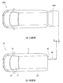
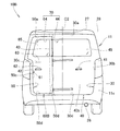
- FIG. 2 is a rear view of the vehicle shown in FIG. 1.
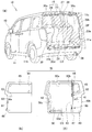
- FIG. 2 is an exploded perspective view of the vehicle shown in FIG. 1.
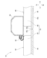
- FIG. 5 is a sectional view taken along line 5-5 in FIG.
- FIG. 6 is a cross-sectional view taken along line 6-6 in FIG. It is action
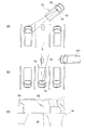
- FIG. 2 is an operation explanatory diagram when the vehicle shown in FIG. 1 is running.
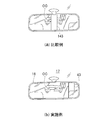
- FIG. 2 is an operation explanatory diagram of a room mirror when the vehicle shown in FIG. 1 is traveling.
- FIG. 2 is an operation explanatory diagram when the vehicle shown in FIG. 1 is parked. It is a figure explaining the detail of the door shown by FIG. It is a figure explaining the effect
- left and right refer to the left and right based on the vehicle occupant
- front and rear refer to the front and rear based on the traveling direction of the vehicle.
- Fr indicates front
- Rr indicates rear
- R indicates right
- L indicates left
- Up indicates top
- Dw indicates bottom.
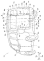
- the vehicle 10 shown in FIG. 1 illustrates a right-hand drive wagon car.
- the vehicle compartment 25 is provided with three rows of seats from the front to the rear of the vehicle body 11.
- An engine Eg as a driving power source is mounted in the engine room Er in front of the passenger compartment 25.
- the traveling power source constitutes a part of the traveling drive system.
- the driver's seat 12 and the passenger seat 13 are provided in the passenger compartment 25 as the first row seats.
- the driver's seat 12 and the passenger seat 13 are individually arranged with a center line C1 extending in the front-rear direction at the center in the vehicle width direction. That is, the driver's seat 12 and the passenger seat 13 are arranged offset with respect to the center line C1.
- a driver's seat 12 is provided to the right of the center line C1
- a passenger seat 13 is provided to the left of the center line C1.
- a second row seat 14 and a third row seat 15 that extend in the vehicle width direction and can be seated by three persons are provided.
- the second row seat 14 includes a main seat 21 having a wide width that can be seated by two persons, and a sub-seat 22 that can be seated by one person having a narrower width than the main seat 21.
- the third row seat 15 includes a main seat 23 that is wide and seatable by two persons, and a sub-seat 24 that can be seated by one person narrower than the main seat 23.
- the second row of sub-sheets 22 can be folded toward the left end of the vehicle body 11.
- the sub-rows 24 in the third row are also configured to be foldable toward the left end of the vehicle body 11.
- a well-known mechanism can be adopted as the mechanism by which these are folded. As shown in the figure, a state in which the sub-seat 24 is deployed and an occupant can sit on the sub-seat 24 is referred to as a deployed state. As will be described later, a state in which the sub seat 24 is folded and the occupant can pass the side of the main seat 23 is referred to as a retracted state.
- the main seat 21 in the second row is referred to as “front seat 21” as appropriate.
- the second row sub-sheet 22 is referred to as “front sub-sheet 22”
- the third row main sheet 23 is referred to as “sheet 23”.
- a luggage compartment 16 for placing luggage is formed at the rear of the third row sheet 15.
- a tailgate 40 for loading / unloading luggage into / from the luggage compartment 16 is swingably attached.
- the luggage compartment 16 constitutes a part of the passenger compartment 25.
- a room mirror 18 for confirming the rear of the occupant Mn is attached on the center line C1 of the front window 17.
- Side mirrors 19 and 19 are attached to the left and right ends of the front portion of the vehicle body 11 for the occupant to confirm the side and the rear.
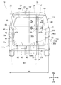
- a rear opening 30 is formed on the rear surface of the vehicle 10 in the vehicle width direction and the entire vertical direction.
- a tailgate 40 is attached so that the rear opening 30 can be opened and closed.
- the tailgate 40 constitutes the rear surface of the vehicle in the closed state.
- a boarding opening 50 is formed over the entire height direction of the tailgate 40.
- the boarding / alighting opening 50 is an opening formed for passengers to get on and off, and is formed in a part of the tailgate 40 in the vehicle width direction.
- a door 60 is attached to the passenger opening 50 so as to be opened and closed.
- the discharge port 26 faces the rear surface of the vehicle 10.
- the exhaust port 26 is a part that exhausts exhaust gas (exhaust) generated in the engine (FIG. 1, symbol Eg) to the outside of the vehicle, and is a tip part of an exhaust system component.
- the discharge port 26 is offset toward the driver's seat with respect to the passenger opening 50. In other words, the discharge port 26 is located closer to the right end portion of the vehicle body 11 than the center line C4 between the vehicle width direction center line C2 of the vehicle body 11 and the right end portion of the vehicle body 11.
- the rear opening 30 formed on the rear surface of the vehicle 10 has a substantially rectangular shape (including a substantially square shape), an upper edge 30a formed in the width direction in the vicinity of the roof 27 of the vehicle body 11, and the upper edge 30a.
- Left and right side edges 30b and 30c (b is a subscript indicating the right side edge; c is a subscript indicating the left side edge) and these are lowered along the vehicle width direction end of the vehicle body from both ends.
- the lower edge 30d is formed by connecting the lower ends of the left and right side edges 30b, 30c.
- the tailgate 40 is attached to the upper part of the vehicle body 11 so as to be swingable up and down on a first opening / closing shaft 28 extending in the horizontal direction.
- a tailgate knob 41 (opening operation means 41) capable of opening the tailgate 40 is provided on the vehicle exterior surface of the tailgate 40.
- the tailgate 40 can be swung in the vertical direction by holding the tailgate knob 41.
- the latch device In the closed state of the tailgate 40, the tailgate 40 is kept closed by the latch device. This latch device can be released by operating the tailgate knob 41.
- the tailgate knob 41 is provided only on the outer surface of the tailgate 40, and the tailgate knob 41 is not provided on the inner surface. This is to prevent the tailgate 40 attached over the entire vehicle width direction from being accidentally opened from the inside of the vehicle.
- a striker 42 is attached to the left end of the tailgate 40 to keep the door 60 closed.
- a pillar 43 is formed in the vicinity of the entrance opening 50 formed in the tailgate 40 in the vertical direction.
- the pillar 43 is formed integrally with the tail gate 40. Since the pillar 43 is formed in the tailgate 40, the rigidity can be increased with respect to the external force that can be received from the rear of the vehicle 10.
- the strength of the tailgate 40 is weaker than when the entrance / exit opening 50 is not provided. If the strength is low, elastic deformation may occur in the peripheral portion of the entrance opening 50 due to vibration received from the road surface while the vehicle is traveling.
- the pillar 43 is provided along the side edge of the opening 50 for getting on and off. By being provided along the side edge of the entrance / exit opening 50 in the vertical direction, the strength of the tailgate 40 can be increased and the occurrence of elastic deformation can be suppressed.
- a tailgate window 44 that is an opening for confirming the outside of the vehicle from the passenger compartment is formed on the tailgate 40.
- the tailgate window 44 is covered with a glass tailgate window panel 45.
- the tailgate window panel 45 covers the tailgate window 44 and also covers the outside of the pillar 43.
- the rear surface remaining portion 40b is formed in a portion excluding the vehicle body rear portion 11c forming the peripheral edge of the rear surface, and in a portion excluding the entry / exit opening 50.
- the discharge port 26 is offset in the vehicle width direction with respect to the entry / exit opening 50 and is located only at a portion overlapping the remaining portion 40b.
- the remaining portion 40b can be regarded as a portion of the tailgate 40 excluding the entrance / exit 50 for getting on and off.
- the entrance / exit 50 has a substantially rectangular shape, and an upper edge 50a formed along the upper edge 30a of the rear opening 30 and a side edge 50b that is lowered from one end of the upper edge 50a and extends along the pillar 43. And a side edge 50c that is lowered from the other end of the upper edge 50a and extends along the side edge 30c of the rear opening 30, and a lower edge 50d that connects the lower ends of these side edges 50b and 50c. .
- the center line C2 extending in the vertical direction at the center of the vehicle width is sandwiched between the side edges 50b and 50c of the opening 50 for getting on and off.
- the left and right side edges 50b, 50c of the entrance / exit 50 are offset to portions avoiding the center of the vehicle width.
- the width in the vehicle width direction of the entrance opening 50 opened in the tailgate 40 is naturally smaller than the width of the rear opening 30.
- a center line C ⁇ b> 2 extending in the vertical direction is orthogonal to the first opening / closing shaft 28.
- the left and right side edges 50b, 50c of the entry / exit opening 50 are located on the vehicle width direction center line C2 side of the vehicle body 11 with respect to the center line C4 with the right end portion.
- the center line C3 in the vehicle width direction of the entrance 50 is offset to the left with respect to the center line C2 extending in the vertical direction.
- the vehicle width direction center line C3 of the passenger opening 50 is offset to the front passenger seat side with respect to the center line C2 (vehicle width direction center line of the vehicle body 11) extending vertically in the vehicle width center. Is located.
- the door 60 is supported by the pillar 43 via two hinges 80, and has a so-called side-opening configuration.
- An axis that passes through the centers of the two hinges 80 and extends in the vertical direction is referred to as a second opening / closing axis 47, and the door 60 swings about the second opening / closing axis 47.
- the door 60 swings in the front-rear direction and the horizontal direction of the vehicle body 11.
- a door latch 61 is attached to the left end of the door 60.
- the door latch 61 engages with a striker 42 provided on the tailgate 40 to maintain the door 60 in a closed state.
- the door latch 61 includes an outer handle 62 that is swingably attached to the outer surface of the door 60 or an inner handle 63 (release operation means 63) that is swingably attached to the inner surface of the door 60. It is set as the structure which can be cancelled
- a known configuration can be adopted for the striker 42, the door latch 61, the outer handle 62, and the inner handle 63.
- the operator releases the locked state by swinging the outer handle 62 or the inner handle 63, and swings the door 60.
- the door 60 swings from the passenger seat side end toward the vehicle width center. That is, the left side edge 50 c of the entry / exit opening 50 is a start end that starts to open by the door 60.
- the outer handle 62 and the inner handle 63 are both provided on the start end side where the door 60 starts to open, and overlap each other with respect to the vehicle width direction. Whether opening from the inside of the vehicle or from the outside of the vehicle, the opening operation of the door 60 can be performed from the vicinity of the start end, and the workability is good.
- the inner handle 63 is attached at a position higher than the outer handle 62.
- a door window portion 64 that is an opening for confirming the outside of the vehicle from the passenger compartment is formed on the upper portion of the door 60 continuously from the tailgate window portion 44.
- the door window 64 is covered with a glass door window panel 65.
- the tailgate window 44 and the door window 64 have the same height (the same length in the vertical direction) and are located at the same position in the height direction. As a result, the tailgate window 44 and the door window 64 are integrally continuous in the vehicle width direction.
- the tailgate window 44 and the door window 64 are collectively referred to as “window 70” as appropriate.
- the window portion 70 is formed over the entire vehicle width direction. Since it is formed over the whole, naturally, the window part 70 is formed in the vehicle width center position at least.
- the pillar 43 is continuously formed between the side edge 50 b of the entrance / exit opening 50 located in the vicinity of the tailgate window portion 44 and the tailgate window portion 44 in the vertical direction.
- the window portion 70 is It is formed at a position overlapping the surface CP.
- the side edge 50c of the entrance opening 50 extending along the end in the vehicle width direction extends in the center line C1 extending in the vehicle longitudinal direction and in the vehicle vertical direction. It is located on the opposite side to the driver's seat 12 with respect to the vehicle width center C2.
- the side edge 50b of the opening 50 for getting on and off at the vehicle width center side is located on the driver's seat 12 side with respect to the center line C1 extending in the vehicle longitudinal direction and the vehicle width center C2 extending in the vehicle vertical direction. ing.
- the pillar 43 and the second opening / closing shaft 47 are attached to a position overlapping the driver's seat 12 when the vehicle body 11 is viewed from the rear.
- the second opening / closing shaft 47 extends to the side portion of the side edge 50 b of the passenger opening 50. It can be said that the side edge 50b of the passenger opening 50 is a side edge on the driver's seat 12 side.
- the travel drive system includes a stack as an energy source for operating a motor.
- the traveling drive system includes a traveling power source and this energy source.
- door window panel 65 Any material can be used for the door window panel 65 as long as it is a transparent panel such as a resin panel in addition to glass.
- the door window panel 65 will be referred to as “door window glass 65” as appropriate.
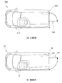
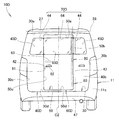
- the seat 23 is disposed adjacent to the rear surface of the vehicle 10, and the right end is located at the right end of the vehicle body 11. That is, one end 23a in the vehicle width direction of the seat 23 is positioned at one end 11a in the vehicle width direction of the vehicle body 11 and overlaps the remaining portion (FIG. 2, reference numeral 40b). On the other hand, the other end 23b in the vehicle width direction of the seat 23 is a portion that overlaps with the entrance opening 50 in the vehicle width direction, and is closer to the one end 11a of the vehicle body 11 than the center line C3 in the vehicle width direction of the entrance opening 50. Is located.
- Two headrests 29 and 29 are provided on the upper portion of the seat 23.
- the sub-seat 24 arranged continuously with the seat 23 extends from the other end 23 b in the vehicle width direction of the seat 23 to the other end 11 b in the vehicle width direction of the vehicle body 11.
- the outer handle 62 is provided at a position avoiding the seat 23 with respect to the vehicle width direction.
- the inner handle 63 that overlaps the outer handle 62 in the vehicle width direction is also attached at a position avoiding the seat 23.
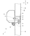
- the door 60 mounting structure will be described in detail with reference to FIG. 5, the door 60 is supported via a hinge 80 by a pillar 43 having a closed cross section. A seal member 85 and a hinge 80 that seal the door 60 and the vehicle interior are attached to the pillar 43. By making the pillar 43 into a closed cross-sectional shape, the rigidity of the pillar 43 can be increased.
- the hinge 80 is substantially L-shaped, and has a bottom portion 81 attached to the pillar 43, an arm portion 82 extending from the bottom portion 81 toward the rear of the vehicle body, and attached to the tip of the arm portion 82 to swing the door 60. It consists of a pin 83 that supports it and a reinforcing portion 84 that passes between the bottom portion 81 and the arm portion 82 and reinforces them. An attached member 67 is fastened to the door 60, and a pin 83 is passed through the attached member 67.
- the door 60 is attached to the tailgate 40 by a hinge 80 so as to be swingable in the longitudinal direction of the vehicle body. Since the door 60 is swingably supported by the hinge 80, the support structure of the door 60 can be simplified.
- the support rigidity of the door 60 can be increased by supporting the door 60 with the hinge 80 on the highly rigid pillar 43.
- each window glass 45 and 65 is mutually facing directly. Since the edges 45a and 65a of the window glasses 45 and 65 are directly opposed to each other, when the vehicle 10 is viewed from the rear, the window glasses 45 and 65 can be seen integrally, thereby improving the design of the vehicle. Can be increased.
- edges 45a and 65a of the window glasses 45 and 65 both have an arc shape.
- the door window glass 65 swings together with the door 60.
- they are prevented from interfering with each other when swinging.
- the edges 45a and 65a of the window glasses 45 and 65 can be arranged closer to each other, and the design can be further improved.
- the rear opening 30 opens over substantially the entire range in the height direction of the rear surface of the vehicle 10, and the passenger opening 50 opens over almost the entire range in the height direction of the tailgate 40. Yes. A person can get on and off from the rear of the vehicle 10 by using the opening 50 for getting on and off.
- an inner handle 63 capable of releasing the door latch 61 is provided on the inner surface of the door 60.
- the door 60 can be opened and closed by an operation from the inside of the vehicle, and the occupant can get off from the rear of the vehicle body 11. That is, passengers can get on and off from the inside of the vehicle, so that the boarding / exiting property is improved.
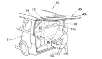
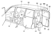
- the door 60 when the small luggage SC is loaded on the vehicle 10, the door 60 is swung in the horizontal direction. The door 60 starts to open from the side edge 50c on the end side in the vehicle width direction of the passenger opening 50. Since the door 60 is a part of the tailgate 40, the door 60 is lighter than the tailgate 40. Since it is lighter than the tailgate 40, the opening / closing operation is easy and the operability is excellent.
- the entrance / exit opening 50 is opened over the entire range of the left half of the tailgate 40.
- the small loads SC are loaded and unloaded from the boarding / unloading opening 50, and a hinge 80 for supporting the door 60 is attached to a portion of the tailgate 40 where the boarding / unloading opening 50 is not formed.
- the hinge 80 for supporting the door 60 while securing the area of the opening necessary for loading and unloading the small luggage SC by making the entire left half of the tailgate 40 the entrance opening 50. Sufficient space can be secured.
- the vehicle 10 having such a boarding / alighting opening 50 further exhibits the effects described in the next figure.
- the discharge port 26 is offset in the vehicle width direction with respect to the entrance opening 50. Thereby, the passenger can get on and off the vehicle while avoiding the discharge port 26. That is, the occupant can get on and off while avoiding emissions such as exhaust gas and water. It can be said that the vehicle 10 has a high boarding / exiting property.
- the vehicle width direction center line C3 of the boarding opening 50 and the discharge port 26 are arranged so as to sandwich the vehicle width direction center line C2 of the vehicle body 11. Thereby, the distance of the opening 50 for boarding / alighting and the discharge port 26 can be separated. Thus, the discharge port 26 can be separated from the passenger getting on and off.
- the side edge 50 c on the vehicle width direction other end 11 b side of the vehicle body 11 is a start end that starts to open by the door 60. That is, the door 60 starts to open from the side edge 50 c far from the seat 23.
- the start end is the side edge 50b closer to the seat 23, it is necessary to open more doors 60 so that the seat 23 does not prevent getting on and off when getting on and off. For this reason, by setting it as the structure which begins to open the door 60 from the side edge 50c far from the sheet
- the side edge 50c can also be referred to as the side edge 50c far from the discharge port 26 among the left and right side edges 50b, 50c of the entry / exit opening 50. Since the door 60 is opened from the side edge 50c far from the discharge port 26, the occupant can get on and off the vehicle while avoiding exhausts such as exhaust gas and water.
- an outer handle 62 that opens and closes the door 60 is attached to the outer surface of the door 60 in the vicinity of the side edge 50 c on the start end side. Since the outer handle 62 is located on the start end side, the passenger can get on and off the vehicle 10 without approaching the discharge port 26 when opening the door 60 from the outside of the vehicle 10.
- the inner handle 63 is provided at a position avoiding the seat 23 when the door 60 is closed. Thereby, it can prevent that the sheet
- the inner handle 63 is provided on the other end 11b side with respect to the center line C3 in the vehicle width direction of the passenger opening 50 when the door 60 is closed. Since the inner handle 63 is provided on the opening start end side of the door 60, the occupant is positioned on the opening start end side when the inner handle 63 is operated, and boarding / exiting can be performed more smoothly.
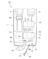
- the sub-sheet 24 positioned on the side of the sheet 23 is configured to be displaceable so that it can pass on the side of the sheet 23.
- the occupant can be seated after getting on and off while the occupant can get on and off from the rear of the vehicle body 11, and a large number of occupants can get on.
- the other end 23 b in the vehicle width direction of the seat 23 is located at a portion overlapping the entrance opening 50 in the vehicle width direction.
- the headrest 29 is located in the center of the vehicle width and overlaps the opening 50 for getting on and off in the vehicle width direction. A tall occupant can grab and ride the headrest 29, which is more beneficial.
- the seat 23 is disposed adjacent to the opening 50 for getting on and off to such an extent that an occupant can grip it when getting on.
- the sub-seat 24 has a structure that is folded toward the other end 11b side of the vehicle body 11 in the vehicle width direction.
- the folded sub-seat 24 can be gripped. Thereby, boarding / exiting property further improves.
- a so-called flip-up structure can be given.
- the headrest 29 overlaps with the opening 50 for getting on and off.
- a front seat 21 is provided in front of the seat 23, and a front sub-sheet 22 is provided in front of the sub-sheet 24.
- the front sub-sheet 22 is configured to be displaceable so that it can pass through the side of the front sheet 21.
- the sheet width of the sheet 23 is larger than the sheet width of the sub-sheet 24.
- a larger number of passengers can be seated without deploying the sub-seat 24.
- the vehicle width direction other end 23b of the seat 23 is located on the vehicle width direction one end 11a side of the vehicle body 11 with respect to the vehicle width direction center line C3 of the entrance / exit opening 50.
- the length of the seat 23 overlapping the boarding opening 50 is less than half the width of the boarding opening 50.
- the operation of the vehicle 10 during traveling will be described with reference to FIGS.
- the pillar 143 overlaps most of the other vehicles OC traveling behind. . Since it overlaps most, it is difficult for the occupant to visually recognize the other vehicle OC through the room mirror 118. In particular, if the distance between the vehicle 110 and another vehicle OC traveling behind is increased, the other vehicle OC may completely overlap the pillar 143 and may not be visible.
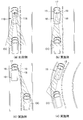
- region which is pinched by the line extended from the room mirror 118 shown by Fig.10 (a), and is shown with the oblique line is an area
- the pillar 43 disposed on the right side (driver's seat side) of the vehicle body 11 blocks a part of the field of view of the room mirror 18. However, since the pillar 43 is moved to the right side, another vehicle OC traveling behind the vehicle 10 can be confirmed by the room mirror 18.
- the vehicle 10 can sufficiently check the subsequent vehicle OC even during the traveling of the curve.
- FIG. 12 (a) the vehicle 10 is retracted to the parking lot P of the store and parked, or as shown in FIG. 12 (b), the driver's seat The vehicle 10 may be moved backward from the opposite side to a place where another vehicle OC is traveling.
- the driver 43 can obtain a wide field of view because the pillar 43 is disposed at a portion overlapping the driver's seat.
- FIG. 3 can be referred to as follows.
- the side edges 50b and 50c of the entrance / exit opening 50 are located at a position avoiding the vehicle width center C2 of the vehicle body 11, and a window portion 70 is provided at the vehicle width center position C2 of the tailgate 40.
- a minimum field of view can be secured. Since the side edges 50b and 50c of the boarding / alighting opening 50 are located at portions avoiding the window portion 70, the side edges 50b and 50c of the boarding / alighting opening 50 are prevented from obstructing the field of view. That is, the vehicle 10 according to the present invention can be said to be a vehicle that can ensure high visibility while the door 60 is attached.
- the door window portion 64 is formed across both ends of the door 60 in the vehicle width direction, and the tailgate window portion 44 is a portion of the tailgate 40 in the vehicle width direction where the door window portion 64 is not formed. It is formed over. That is, the window part 70 is formed over the vehicle width direction.
- the tailgate window 44 and the door window 64 are located at substantially the same height with respect to the tailgate 40. That is, the tailgate window 44 and the door window 64 are formed continuously. A continuous field of view can be obtained in the height direction.
- the vehicle body 11 is provided with a driver seat 12 that is offset with respect to the center C1 and C2 in the vehicle width direction, and the pillar 43 (second opening / closing shaft 47) is positioned so as to overlap the driver seat 12 when the vehicle body 11 is viewed from the rear. Installed on. That is, the pillar 43 (second opening / closing shaft 47) is provided at a position overlapping the driver's seat 12. In the front-rear direction of the vehicle 10, the portion overlapping the driver's seat 12 is a portion that is difficult for the driver Mn to see. In other words, the pillar 43 (second opening / closing shaft 47) is provided to avoid a portion that is easy to enter the field of view of the driver Mn. By avoiding a part that easily enters the field of view of the driver Mn, the field of view of the driver Mn can be secured satisfactorily.
- the side edge 50b on the vehicle width center side of the entrance / exit opening 50 is located on the driver's seat 12 side with respect to the center lines C1 and C2. Since the side edge 50b on the vehicle width center side of the entrance / exit opening 50 is located on the driver's seat 12 side, the boundary between the door window portion 64 and the tailgate window portion 44 is also located on the driver's seat 12 side. By locating the boundary between the door window portion 64 and the tailgate window portion 44 at a position behind the driver seat 12 that is difficult for the driver Mn to visually recognize, the visibility of the driver Mn can be further ensured.
- the vehicle 200 having only the tailgate 240 needs to always open the tailgate 240 when loading and unloading luggage.
- the tailgate 240 protrudes toward the rear of the vehicle by the height of the tailgate 240.
- the vehicle 10 has a door 60 attached to a part of the tailgate.
- the door 60 is attached to a part of the tailgate 40.
- the protrusion amount of the door 60 to the rear of the vehicle 10 can be suppressed by the protrusion difference ⁇ , compared with the case where the tailgate 40 is opened.
- the door 360 opens and closes from the vehicle width center toward the vehicle width end. That is, the door 360 opens from the side edge 350b on the vehicle width center side.
- a long baggage Ca such as a golf bag or a stroller
- the front end of the luggage Ca may contact the rear seat 315 and may not be stored well.
- the door 60 of the vehicle 10 opens from the end in the vehicle width direction toward the center of the vehicle width. Since the door 60 is open toward the center of the vehicle width, it is only necessary to slightly tilt the luggage Ca with respect to the vehicle width direction when storing the long luggage Ca. That is, the inclination angle ⁇ 2 can be small. Since it is only necessary to incline a little, the third row sheet does not interfere during storage. Since the third row sheet does not interfere, the long luggage Ca can be easily stored.
- the door 360 starts to open from the vicinity of the end of the tailgate 340 on the driver seat side.
- the door knob for opening the door 360 is attached in the vicinity of the portion where the door 360 starts to open, that is, the end on the driver's seat side.
- the occupant who opens the door 360 first moves from the passenger seat 313 to the rear corner portion of the vehicle 300. Then, the vehicle moves from the rear corner portion to the rear right end of the vehicle 300 and opens the door 360.
- the door 60 starts to open from the vicinity of the end of the tailgate 40 in the vehicle width direction.
- a door knob (see reference numeral 62 in FIG. 3) for opening the door 60 is attached in the vicinity of a portion where the door 60 starts to open.
- the passenger who opens the door 60 first moves from the passenger seat 13 to the rear corner of the vehicle 10. Since the rear corner portion of the vehicle 10 and the end portion of the tailgate 40 in the vehicle width direction are close to each other, a door knob for opening the door 60 is also attached in the vicinity thereof. For this reason, the occupant can open the door 60 without moving the vehicle rear to the center of the vehicle width. Since the vehicle rear does not move to the center of the vehicle width, the movement distance of the vehicle periphery can be shortened.
- the driver's seat 12 is arranged offset to one side with respect to the center lines C1 and C2, and one side edge (FIG. 4, reference numeral 50c) of the entrance / exit opening 50 is the driver's seat. 12 is located on the opposite side. That is, the side edge of the entrance opening 50 where the door 60 begins to open is located on the passenger seat 13 side.
- loading and unloading work can be easily performed at a position away from the roadway by adopting a configuration in which the door 60 starts to open from the end on the passenger seat 13 side.
- FIG. 16 shows a vehicle according to the second embodiment, corresponding to FIG.
- the tailgate knob 41A (opening operation means 41) is located at a portion avoiding the discharge port 26 in the vehicle width direction. Also in the vehicle 10A according to the second embodiment configured as described above, the predetermined effect of the present invention can be obtained.
- FIG. 17 shows a vehicle according to the third embodiment, corresponding to FIG.
- the vehicle 10B is a sliding door in which the door 60B slides in the vehicle width direction.
- a sliding door can also be said to be a kind of side-opening door.
- the predetermined effect of the present invention can be obtained.
- the vehicle 10B according to the third embodiment does not have a hinge (FIG. 4, reference numeral 80) and a second opening / closing shaft (FIG. 3, reference numeral 47).
- FIG. 18 shows a vehicle according to the fourth embodiment, corresponding to FIG.
- the door 60 ⁇ / b> C opens from the end in the vehicle width direction. That is, the second opening / closing shaft 47C is formed at the end in the vehicle width direction.
- the predetermined effect of the present invention can be obtained. Note that the vehicle 10C according to the fourth embodiment does not have the pillar (FIG. 3, reference numeral 43).
- FIG. 19 shows a vehicle according to the fifth embodiment, corresponding to FIG.
- the vehicle 10D has a door 60D formed at the center of the tailgate 40D.
- the door window glass 65D is disposed at the center of the vehicle width, and the two tailgate window glasses 45D and 45D are disposed so as to sandwich the door window glass 65D. That is, the window portion 70D includes a door window glass 65D and two tailgate window glasses 45D and 45D.
- the predetermined effect of the present invention can be obtained.
- FIG. 20 shows a vehicle according to the sixth embodiment, corresponding to FIG. 9B.
- the vehicle 10 ⁇ / b> E has a configuration in which the sub seat 24 ⁇ / b> E can be stored on the floor of the passenger compartment, and the front sub seat 22 ⁇ / b> E can move forward and can be folded. Yes. Also in the vehicle 10E according to the sixth embodiment configured as described above, the predetermined effect of the present invention can be obtained.
- the seat of the folding structure in the vehicle width direction, the seat of the folding structure in the front-rear direction, or the seat of the storage structure under the floor can be arbitrarily combined as long as the effect of the present invention can be obtained.
- the vehicle according to the present invention has been described by taking a right-hand drive vehicle as an example, it can also be applied to a left-hand drive vehicle.
- a right-hand drive vehicle as an example, it can also be applied to a left-hand drive vehicle.
- by providing the opening for getting on and off and the door in the substantially right half of the rear part of the vehicle it is possible to make appropriate changes such as a configuration in which the door is opened from the end opposite to the driver's seat. It is not limited to these forms.
- each example is used to facilitate understanding of the present invention.
- the present invention is not limited to the form of the embodiment as long as the effects and effects are exhibited.
- each embodiment can be appropriately combined with a different embodiment.
- the vehicle of the present invention is suitable for a wagon type vehicle.
Landscapes
- Engineering & Computer Science (AREA)
- Mechanical Engineering (AREA)
- Aviation & Aerospace Engineering (AREA)
- Transportation (AREA)
- Body Structure For Vehicles (AREA)
- Seats For Vehicles (AREA)
Abstract
Description
この後部開口を開閉可能なテールゲートが車体に取付けられ、
前記テールゲートに、乗員が乗降することができる乗降用開口が形成され、
前記後面に隣接してシートが設けられている車両であって、
前記乗降用開口は、前記後面の中の、車幅方向の一部に形成され、
前記シートの車幅方向一端は、前記車体の車幅方向一端に位置し、
前記シートの車幅方向他端は、前記乗降用開口に対して車幅方向に重なる部位に位置していることを特徴とする車両が提供される。
前記乗降用開口は、前記後面の中の車幅方向の一部に形成され、
前記後面の中の前記乗降用開口を除いた部位に前記後面の残余部が形成され、
前記シートの少なくとも一部は、前記残余部に対して車幅方向に重なり、
前記シートの車幅方向一端は、前記車体の車幅方向一端に位置し、
前記シートの車幅方向他端は、前記乗降用開口に対して車幅方向に重なる部位に位置していることを特徴とする車両が提供される。
このヘッドレストは、車体背面視において、前記乗降用開口と重なっている。
前記乗降用開口の左右の側縁のうち、前記車体の車幅方向他端側の側縁は、前記ドアによって開き始める開始端である。
前記サブシートは、前記シートの側方を通過できるよう、変位可能な構成である。
前記前側サブシートは、前記前側シートの側方を通過できるよう、変位可能な構成である。
図1に示された車両10は、右ハンドルのワゴン車を例示している。車室25には、車体11の前方から後方に向かって座席が3列設けられている。車室25の前方のエンジンルームErには、走行用動力源としてのエンジンEgが搭載されている。詳細は後述するが、走行用動力源は、走行用駆動系の一部を構成する。
図2~図4に示されるように、車両10の後面には車幅方向及び上下方向の全体に渡って後部開口30が形成されている。この後部開口30を開閉可能に、テールゲート40が取付けられている。テールゲート40は、閉じ状態において車両の後面を構成する。このテールゲート40の高さ方向の全体に渡って乗降用開口50が形成されている。乗降用開口50は、乗員の乗降のために形成されている開口であり、テールゲート40の車幅方向の一部に形成されている。この乗降用開口50には、開閉可能にドア60が取付けられている。
図5に示されるように、ドア60は、閉断面状のピラー43によって、ヒンジ80を介して支持されている。ピラー43には、ドア60と車室内とをシールするシール部材85及びヒンジ80が取付けられている。ピラー43を閉断面状にすることにより、ピラー43の剛性を高めることができる。
図6に示されるように、各窓ガラス45,65の1つの縁45a,65a同士は、互いに直接に対向している。各窓ガラス45,65の縁45a,65a同士が互いに直接に対向していることにより、車両10を後方から見た際に、各窓ガラス45,65が一体的に見え、車両の意匠性を高めることができる。
図7に示されるように、大きな荷物BCを車両10に積み込む場合には、テールゲート40を上方にスイングさせる。後部開口30が車両10の後面全体に開口しているので、容易に大きな荷物を積み込むことができる。
乗降用開口50は、テールゲート40の略左半分の全範囲にわたって開口している。ドア60を開けた際の小さな荷物SCの積み卸しは、乗降用開口50から行い、テールゲート40の乗降用開口50が形成されない部位には、ドア60を支持するためのヒンジ80が取付けられる。テールゲート40の略左半分の全範囲を乗降用開口50とすることにより、小さな荷物SCの積み卸しに必要な開口の面積を確保しつつ、ドア60を支持するためのヒンジ80を取付けるために必要なスペースを十分に確保することができる。このような乗降用開口50を有する車両10は、次図において説明するような効果をさらに奏する。
図10(a)及び図11(a)の比較例に示されるように、ピラー143が車幅中央に延びている場合には、ピラー143が後方を走行する他の車両OCの大部分に重なる。大部分に重なるため、乗員は他の車両OCをルームミラー118を介して視認し難い。特に、車両110と後方を走行する他の車両OCとの距離が離れると、他の車両OCがピラー143に完全に重なり、視認できなくなる虞がある。
図12(a)に示されるように、車両10を店舗の駐車場Pに後退させて駐車することや、図12(b)に示されるように、高速道路のサービスエリアのように、運転席とは逆側から他の車両OCが走行している場所に車両10を後退させる場合がある。
乗降用開口50の側縁50b,50cは、車体11の車幅中央C2を避けた部位に位置していると共に、テールゲート40の車幅中央位置C2に窓部70が設けられている。少なくとも中央位置C2に窓部70が設けられていることにより、最低限の視界を確保することができる。乗降用開口50の側縁50b,50cが、窓部70を避けた部位に位置していることにより、乗降用開口50の側縁50b,50cが視界の妨げになることを防止する。即ち、本発明による車両10は、ドア60が取付けられていながらも、高い視認性を確保することのできる車両ということができる。
車体11には、車幅方向中心C1,C2に対しオフセットした運転席12が配置され、ピラー43(第2開閉軸47)は、車体11を後方から見た場合に、運転席12に重なる位置に取付けられている。即ち、ピラー43(第2開閉軸47)は、運転席12に重なる位置に設けられている。車両10の前後方向において、運転席12に重なる部位は、運転者Mnにとって目視するのが困難な部位である。即ち、運転者Mnの視界に入りやすい部位を避けてピラー43(第2開閉軸47)を設けた。運転者Mnの視界に入りやすい部位を避けることにより、運転者Mnの視界を良好に確保することができる。
図13(a)に示されるように、テールゲート240のみを有する車両200は、荷物の積み卸しをする際に、常にテールゲート240を開ける必要がある。テールゲート240を開くと、テールゲート240の高さ分だけテールゲート240が車両の後方に突出する。
図16は実施例2による車両を示し、上記図3に対応させて表している。
図17は実施例3による車両を示し、上記図3に対応させて表している。
このように構成した実施例3による車両10Bにおいても、本発明所定の効果を得ることができる。ドア60Bをスライドドアによって形成することにより、車両後方への突出量をさらに小さくすることができる。なお、実施例3による車両10Bは、ヒンジ(図4、符号80)及び第2開閉軸(図3、符号47)を有していない。
図18は実施例4による車両を示し、上記図3に対応させて表している。
図18に示されるように、車両10Cは、ドア60Cが車幅方向の端部から開く。即ち、第2開閉軸47Cは、車幅方向の端部に形成されている。このように構成した実施例4による車両10Cにおいても、本発明所定の効果を得ることができる。なお、実施例4による車両10Cは、ピラー(図3、符号43)を有していない。
図19は実施例5による車両を示し、上記図3に対応させて表している。
図20は実施例6による車両を示し、上記図9(b)に対応させて表している。
11…車体
11a…車体の車幅方向一端
11b…車体の車幅方向他端
21…メインシート(前側シート)
22,22E…サブシート(前側サブシート)
23…メインシート(シート)
23a…シートの車幅方向一端
23b…シートの車幅方向他端
24,24E…サブシート
25…車室
29…ヘッドレスト
30…後部開口
40,40A…テールゲート
40b…残余部
50,50A…乗降用開口
50b…乗降用開口の側縁
50c…乗降用開口の側縁(開始端)
60,60A,60B,60C,60D…ドア
C2…車幅中央において上下方向に延びている中心線(車体の車幅方向中心線)
C3…乗降用開口の車幅方向中心線
Claims (10)
- 後面の車幅方向全域にわたって後部開口が形成され、
この後部開口を開閉可能なテールゲートが車体に取付けられ、
前記テールゲートに、乗員が乗降することができる乗降用開口が形成され、
前記後面に隣接してシートが設けられている車両であって、
前記乗降用開口は、前記後面の中の、車幅方向の一部に形成され、
前記シートの車幅方向一端は、前記車体の車幅方向一端に位置し、
前記シートの車幅方向他端は、前記乗降用開口に対して車幅方向に重なる部位に位置していることを特徴とする車両。 - 後面に乗降用開口が形成されていると共に、前記後面に隣接してシートが設けられている車両であって、
前記乗降用開口は、前記後面の中の車幅方向の一部に形成され、
前記後面の中の前記乗降用開口を除いた部位に前記後面の残余部が形成され、
前記シートの少なくとも一部は、前記残余部に対して車幅方向に重なり、
前記シートの車幅方向一端は、前記車体の車幅方向一端に位置し、
前記シートの車幅方向他端は、前記乗降用開口に対して車幅方向に重なる部位に位置していることを特徴とする車両。 - 前記シートの車幅方向他端は、前記乗降用開口の車幅方向中心線よりも、前記車体の車幅方向一端側に位置している、請求項1又は請求項2記載の車両。
- 前記シートの上部には、ヘッドレストが設けられ、
このヘッドレストは、車体背面視において、前記乗降用開口と重なっている、請求項1~請求項3のいずれか1項記載の車両。 - 前記乗降用開口の左右の側縁は、前記車体の車幅方向中心線から車幅方向にオフセットしている、請求項1~請求項4のいずれか1項記載の車両。
- 前記乗降用開口を開閉可能なドアを有し、
前記乗降用開口の左右の側縁のうち、前記車体の車幅方向他端側の側縁は、前記ドアによって開き始める開始端である、請求項1~請求項5のいずれか1項記載の車両。 - 前記シートの車幅方向他端から前記車体の車幅方向他端まで延びているサブシートが設けられ、
前記サブシートは、前記シートの側方を通過できるよう、変位可能な構成である、請求項1~請求項6のいずれか1項記載の車両。 - 前記シートのシート幅は、前記サブシートのシート幅よりも大きいことを特徴とする請求項7記載の車両。
- 前記サブシートは、前記車体の車幅方向他端側への折りたたみ構造によって変位可能である、請求項8又は請求項9記載の車両。
- 車体背面視において、前記シートの前方に前側シートが設けられると共に、前記サブシートの前方に前側サブシートが設けられ、
前記前側サブシートは、前記前側シートの側方を通過できるよう、変位可能な構成である、請求項7~請求項9のいずれか1項記載の車両。
Priority Applications (4)
| Application Number | Priority Date | Filing Date | Title |
|---|---|---|---|
| CN201480022871.1A CN105142946A (zh) | 2013-04-23 | 2014-04-22 | 车辆 |
| US14/782,687 US9738141B2 (en) | 2013-04-23 | 2014-04-22 | Vehicle |
| EP14788260.9A EP2998143B1 (en) | 2013-04-23 | 2014-04-22 | Vehicle |
| JP2015513761A JP6215918B2 (ja) | 2013-04-23 | 2014-04-22 | 車両 |
Applications Claiming Priority (2)
| Application Number | Priority Date | Filing Date | Title |
|---|---|---|---|
| JP2013090576 | 2013-04-23 | ||
| JP2013-090576 | 2013-04-23 |
Publications (1)
| Publication Number | Publication Date |
|---|---|
| WO2014175240A1 true WO2014175240A1 (ja) | 2014-10-30 |
Family
ID=51791813
Family Applications (1)
| Application Number | Title | Priority Date | Filing Date |
|---|---|---|---|
| PCT/JP2014/061226 Ceased WO2014175240A1 (ja) | 2013-04-23 | 2014-04-22 | 車両 |
Country Status (5)
| Country | Link |
|---|---|
| US (1) | US9738141B2 (ja) |
| EP (1) | EP2998143B1 (ja) |
| JP (1) | JP6215918B2 (ja) |
| CN (1) | CN105142946A (ja) |
| WO (1) | WO2014175240A1 (ja) |
Families Citing this family (4)
| Publication number | Priority date | Publication date | Assignee | Title |
|---|---|---|---|---|
| CN105142946A (zh) * | 2013-04-23 | 2015-12-09 | 本田技研工业株式会社 | 车辆 |
| JP6601805B2 (ja) * | 2017-04-28 | 2019-11-06 | 株式会社Subaru | 車両 |
| US11577791B2 (en) | 2020-01-17 | 2023-02-14 | Ventra Group Co. | Vehicle tailgate with pocket and step |
| US11608123B2 (en) | 2020-06-08 | 2023-03-21 | Ventra Group, Co. | Vehicle tailgate with fold out step |
Citations (7)
| Publication number | Priority date | Publication date | Assignee | Title |
|---|---|---|---|---|
| JPS6168935U (ja) * | 1984-10-12 | 1986-05-12 | ||
| JPS63173736A (ja) * | 1987-01-10 | 1988-07-18 | Daihatsu Motor Co Ltd | 自動車の後部座席構造 |
| US5083833A (en) * | 1991-01-18 | 1992-01-28 | Dennis Herrmeyer | Variable size door assembly |
| JPH054519A (ja) * | 1991-03-22 | 1993-01-14 | Mazda Motor Corp | 自動車のバツクドア構造 |
| JP2514650Y2 (ja) | 1988-04-01 | 1996-10-23 | いすゞ自動車株式会社 | 後部ドアに副ドアを併設した車両 |
| JP2004299641A (ja) * | 2003-04-01 | 2004-10-28 | Mazda Motor Corp | 車両の後部車体構造 |
| DE102008020090A1 (de) * | 2008-04-22 | 2009-10-29 | GM Global Technology Operations, Inc., Detroit | Kraftfahrzeug mit Hecköffnung |
Family Cites Families (39)
| Publication number | Priority date | Publication date | Assignee | Title |
|---|---|---|---|---|
| US3193321A (en) * | 1961-10-02 | 1965-07-06 | Floyd R Rose | Mobile home and boat combination |
| DE1288929B (de) | 1963-02-19 | 1969-02-06 | Golde Gmbh H T | Rueckwandtuer fuer Kraftfahrzeuge mit Schiebedach |
| US5524954A (en) * | 1994-07-07 | 1996-06-11 | Gold; Peter | Van rear compartment closure |
| JPH08142680A (ja) | 1994-11-25 | 1996-06-04 | Nissan Shatai Co Ltd | 観音扉 |
| JP3317165B2 (ja) | 1996-02-15 | 2002-08-26 | トヨタ車体株式会社 | 車両用シート |
| US5876086A (en) | 1997-04-14 | 1999-03-02 | The Budd Company | Multi-piece door with hidden hinge |
| US6607231B2 (en) * | 2001-07-23 | 2003-08-19 | Ford Global Technologies, Inc. | Liftgate with low-liftover liftglass |
| US6742826B2 (en) * | 2001-08-08 | 2004-06-01 | J.R. Kennedy Co., Ltd. | Five position tailgate assembly |
| US6513863B1 (en) * | 2002-02-22 | 2003-02-04 | General Motors Corporation | Vehicle interior door apparatus and interlock system |
| US6874839B2 (en) * | 2003-03-07 | 2005-04-05 | General Motors Corporation | Vehicle endgate with integral door |
| US6837529B2 (en) * | 2003-05-22 | 2005-01-04 | General Motors Corporation | Midgate assembly including fixed window and crossbar |
| US6796600B1 (en) * | 2003-05-22 | 2004-09-28 | General Motors Corporation | Vehicle body with pre-hung midgate panel |
| JP2005053315A (ja) | 2003-08-04 | 2005-03-03 | Mazda Motor Corp | 車両の後部開閉構造 |
| CN1309614C (zh) * | 2003-09-02 | 2007-04-11 | 本田技研工业株式会社 | 车辆的后部构造 |
| WO2005042287A1 (en) * | 2003-10-23 | 2005-05-12 | Magna International Inc. | Liftgate frame |
| JP2005297632A (ja) * | 2004-04-07 | 2005-10-27 | Honda Motor Co Ltd | 車両用シート構造 |
| DE102004022426B4 (de) * | 2004-05-06 | 2009-08-20 | Webasto Ag | Heckklappenanordnung |
| US20070024083A1 (en) * | 2005-08-01 | 2007-02-01 | Met'afraun Incorporated | Vehicle drop door |
| DE102005044569B4 (de) * | 2005-09-17 | 2013-01-03 | GM Global Technology Operations LLC (n. d. Ges. d. Staates Delaware) | Hecköffnungssystem |
| US20070222258A1 (en) * | 2006-01-27 | 2007-09-27 | Paul Bacco | Escape hatch |
| US7845712B2 (en) * | 2007-10-12 | 2010-12-07 | Gm Global Technology Operations, Inc. | Vehicle closure assembly with sealed split between independently selectable closure panels |
| DE102007056853A1 (de) | 2007-11-26 | 2009-05-28 | GM Global Technology Operations, Inc., Detroit | Feststeller für das Verschlusselement einer Kfz-Hecköffnung |
| DE102008018333A1 (de) | 2008-04-11 | 2009-10-15 | GM Global Technology Operations, Inc., Detroit | Verschlusselement für eine Kraftfahrzeugöffnung |
| US20100253043A1 (en) * | 2009-04-01 | 2010-10-07 | Featherlite, Inc. | Rear Gate with Open Step-Through Area |
| US8292345B2 (en) * | 2009-06-12 | 2012-10-23 | Toyota Motor Engineering & Manufacturing North America, Inc. | Vehicles with rear hatch assemblies |
| JP5299563B2 (ja) | 2010-04-06 | 2013-09-25 | トヨタ車体株式会社 | 車両のバックドア開口部構造 |
| EP2386435A1 (en) | 2010-05-10 | 2011-11-16 | Tofas Turk Otomobil Fabrikasi Anonim Sirketi | A commercial vehicle with a door assembly |
| US8348325B2 (en) * | 2010-11-18 | 2013-01-08 | Ford Global Technologies, Llc | Vehicle tailgate having pivoting secondary tailgate therein |
| US20120326466A1 (en) | 2011-06-23 | 2012-12-27 | GM Global Technology Operations LLC | Actuation of a power operated tailgate |
| US8608226B2 (en) | 2012-02-08 | 2013-12-17 | GM Global Technology Operations LLC | Vehicle with doors for accessing a storage space |
| JP5647186B2 (ja) | 2012-07-04 | 2014-12-24 | 本田技研工業株式会社 | テールゲート付き車両 |
| JP5639618B2 (ja) * | 2012-07-04 | 2014-12-10 | 本田技研工業株式会社 | テールゲート付き車両 |
| EP2998142B1 (en) * | 2013-04-23 | 2018-09-05 | Honda Motor Co., Ltd. | Vehicle |
| CN105142946A (zh) * | 2013-04-23 | 2015-12-09 | 本田技研工业株式会社 | 车辆 |
| CN105263765B (zh) * | 2013-06-04 | 2018-01-16 | 本田技研工业株式会社 | 车辆 |
| US9463746B2 (en) * | 2014-09-17 | 2016-10-11 | GM Global Technology Operations LLC | Multi-panel hinged endgate assembly with edge support for step panel |
| JP6196600B2 (ja) * | 2014-10-22 | 2017-09-13 | 本田技研工業株式会社 | 車体構造 |
| JP6066976B2 (ja) * | 2014-10-23 | 2017-01-25 | 本田技研工業株式会社 | テールゲート付き車体構造 |
| JP6144661B2 (ja) * | 2014-10-28 | 2017-06-07 | 本田技研工業株式会社 | 車両 |
-
2014
- 2014-04-22 CN CN201480022871.1A patent/CN105142946A/zh active Pending
- 2014-04-22 WO PCT/JP2014/061226 patent/WO2014175240A1/ja not_active Ceased
- 2014-04-22 EP EP14788260.9A patent/EP2998143B1/en not_active Not-in-force
- 2014-04-22 US US14/782,687 patent/US9738141B2/en not_active Expired - Fee Related
- 2014-04-22 JP JP2015513761A patent/JP6215918B2/ja not_active Expired - Fee Related
Patent Citations (7)
| Publication number | Priority date | Publication date | Assignee | Title |
|---|---|---|---|---|
| JPS6168935U (ja) * | 1984-10-12 | 1986-05-12 | ||
| JPS63173736A (ja) * | 1987-01-10 | 1988-07-18 | Daihatsu Motor Co Ltd | 自動車の後部座席構造 |
| JP2514650Y2 (ja) | 1988-04-01 | 1996-10-23 | いすゞ自動車株式会社 | 後部ドアに副ドアを併設した車両 |
| US5083833A (en) * | 1991-01-18 | 1992-01-28 | Dennis Herrmeyer | Variable size door assembly |
| JPH054519A (ja) * | 1991-03-22 | 1993-01-14 | Mazda Motor Corp | 自動車のバツクドア構造 |
| JP2004299641A (ja) * | 2003-04-01 | 2004-10-28 | Mazda Motor Corp | 車両の後部車体構造 |
| DE102008020090A1 (de) * | 2008-04-22 | 2009-10-29 | GM Global Technology Operations, Inc., Detroit | Kraftfahrzeug mit Hecköffnung |
Also Published As
| Publication number | Publication date |
|---|---|
| EP2998143A4 (en) | 2017-05-03 |
| US20160046177A1 (en) | 2016-02-18 |
| JPWO2014175240A1 (ja) | 2017-02-23 |
| EP2998143A1 (en) | 2016-03-23 |
| CN105142946A (zh) | 2015-12-09 |
| EP2998143B1 (en) | 2019-03-13 |
| JP6215918B2 (ja) | 2017-10-18 |
| US9738141B2 (en) | 2017-08-22 |
Similar Documents
| Publication | Publication Date | Title |
|---|---|---|
| JP5639618B2 (ja) | テールゲート付き車両 | |
| JP5647186B2 (ja) | テールゲート付き車両 | |
| JP6215918B2 (ja) | 車両 | |
| JP6225177B2 (ja) | 車両 | |
| JP6095772B2 (ja) | 車両 | |
| JP2005053315A (ja) | 車両の後部開閉構造 | |
| JP6200968B2 (ja) | テールゲート付き車両 | |
| JP6298832B2 (ja) | 車両 | |
| JP2002046472A (ja) | 2ウェイスライド方式の車両用バックドア装置 | |
| JP3254106U (ja) | 車両 | |
| JP4356605B2 (ja) | 荷物運搬車両 | |
| JP2012086614A (ja) | 車両の可動ルーフ構造 | |
| JP5849067B2 (ja) | 車両 | |
| JP5625784B2 (ja) | 車両のオープンルーフ構造 | |
| JP2006088977A (ja) | キャブオーバ型自動車 | |
| CN104428149B (zh) | 带尾门的车辆 | |
| JP2020111239A (ja) | キャノピードア構造 | |
| JP2000344136A (ja) | 自動車におけるシート装置と車体との関連構造 |
Legal Events
| Date | Code | Title | Description |
|---|---|---|---|
| WWE | Wipo information: entry into national phase |
Ref document number: 201480022871.1 Country of ref document: CN |
|
| 121 | Ep: the epo has been informed by wipo that ep was designated in this application |
Ref document number: 14788260 Country of ref document: EP Kind code of ref document: A1 |
|
| ENP | Entry into the national phase |
Ref document number: 2015513761 Country of ref document: JP Kind code of ref document: A |
|
| WWE | Wipo information: entry into national phase |
Ref document number: 14782687 Country of ref document: US |
|
| NENP | Non-entry into the national phase |
Ref country code: DE |
|
| WWE | Wipo information: entry into national phase |
Ref document number: 2014788260 Country of ref document: EP |