WO2014181579A1 - 空気入りタイヤ - Google Patents
空気入りタイヤ Download PDFInfo
- Publication number
- WO2014181579A1 WO2014181579A1 PCT/JP2014/056342 JP2014056342W WO2014181579A1 WO 2014181579 A1 WO2014181579 A1 WO 2014181579A1 JP 2014056342 W JP2014056342 W JP 2014056342W WO 2014181579 A1 WO2014181579 A1 WO 2014181579A1
- Authority
- WO
- WIPO (PCT)
- Prior art keywords
- bead
- core
- tire
- cord
- inner core
- Prior art date
- Legal status (The legal status is an assumption and is not a legal conclusion. Google has not performed a legal analysis and makes no representation as to the accuracy of the status listed.)
- Ceased
Links
Images


Classifications
-
- B—PERFORMING OPERATIONS; TRANSPORTING
- B60—VEHICLES IN GENERAL
- B60C—VEHICLE TYRES; TYRE INFLATION; TYRE CHANGING; CONNECTING VALVES TO INFLATABLE ELASTIC BODIES IN GENERAL; DEVICES OR ARRANGEMENTS RELATED TO TYRES
- B60C15/00—Tyre beads, e.g. ply turn-up or overlap
- B60C15/0009—Tyre beads, e.g. ply turn-up or overlap features of the carcass terminal portion
- B60C15/0018—Tyre beads, e.g. ply turn-up or overlap features of the carcass terminal portion not folded around the bead core, e.g. floating or down ply
-
- B—PERFORMING OPERATIONS; TRANSPORTING
- B60—VEHICLES IN GENERAL
- B60C—VEHICLE TYRES; TYRE INFLATION; TYRE CHANGING; CONNECTING VALVES TO INFLATABLE ELASTIC BODIES IN GENERAL; DEVICES OR ARRANGEMENTS RELATED TO TYRES
- B60C15/00—Tyre beads, e.g. ply turn-up or overlap
- B60C15/04—Bead cores
- B60C15/05—Bead cores multiple, i.e. with two or more cores in each bead
-
- B—PERFORMING OPERATIONS; TRANSPORTING
- B60—VEHICLES IN GENERAL
- B60C—VEHICLE TYRES; TYRE INFLATION; TYRE CHANGING; CONNECTING VALVES TO INFLATABLE ELASTIC BODIES IN GENERAL; DEVICES OR ARRANGEMENTS RELATED TO TYRES
- B60C9/00—Reinforcements or ply arrangement of pneumatic tyres
- B60C9/02—Carcasses
-
- B—PERFORMING OPERATIONS; TRANSPORTING
- B29—WORKING OF PLASTICS; WORKING OF SUBSTANCES IN A PLASTIC STATE IN GENERAL
- B29D—PRODUCING PARTICULAR ARTICLES FROM PLASTICS OR FROM SUBSTANCES IN A PLASTIC STATE
- B29D30/00—Producing pneumatic or solid tyres or parts thereof
- B29D30/06—Pneumatic tyres or parts thereof (e.g. produced by casting, moulding, compression moulding, injection moulding, centrifugal casting)
- B29D30/48—Bead-rings or bead-cores; Treatment thereof prior to building the tyre
-
- B—PERFORMING OPERATIONS; TRANSPORTING
- B60—VEHICLES IN GENERAL
- B60C—VEHICLE TYRES; TYRE INFLATION; TYRE CHANGING; CONNECTING VALVES TO INFLATABLE ELASTIC BODIES IN GENERAL; DEVICES OR ARRANGEMENTS RELATED TO TYRES
- B60C9/00—Reinforcements or ply arrangement of pneumatic tyres
- B60C2009/0071—Reinforcements or ply arrangement of pneumatic tyres characterised by special physical properties of the reinforcements
-
- B—PERFORMING OPERATIONS; TRANSPORTING
- B60—VEHICLES IN GENERAL
- B60C—VEHICLE TYRES; TYRE INFLATION; TYRE CHANGING; CONNECTING VALVES TO INFLATABLE ELASTIC BODIES IN GENERAL; DEVICES OR ARRANGEMENTS RELATED TO TYRES
- B60C15/00—Tyre beads, e.g. ply turn-up or overlap
- B60C15/04—Bead cores
- B60C2015/042—Bead cores characterised by the material of the core, e.g. alloy
-
- B—PERFORMING OPERATIONS; TRANSPORTING
- B60—VEHICLES IN GENERAL
- B60C—VEHICLE TYRES; TYRE INFLATION; TYRE CHANGING; CONNECTING VALVES TO INFLATABLE ELASTIC BODIES IN GENERAL; DEVICES OR ARRANGEMENTS RELATED TO TYRES
- B60C15/00—Tyre beads, e.g. ply turn-up or overlap
- B60C15/04—Bead cores
- B60C2015/046—Cable cores, i.e. cores made-up of twisted wires
Definitions
- the present invention relates to a pneumatic tire, and more particularly, to a pneumatic tire in which an end portion of a carcass ply is sandwiched between an inner core and an outer core in an axial direction of the tire embedded in a bead portion.
- Patent Document 1 proposes a core molding method for producing a pneumatic tire using a core.
- the core has an outer surface equal to the bore surface of the pneumatic tire.
- an inner liner, a carcass ply, a bead core, sidewall rubber, tread rubber and the like are attached to the outer surface of the core.
- the green tire is vulcanized together with the core in the mold so as not to expand and deform in the mold. After vulcanization, the core is disassembled from the tire and taken out.
- the core molding method can provide a pneumatic tire excellent in dimensional stability because deformation of a green tire during vulcanization is small.
- FIG. 9 shows a partial cross-sectional view of the bead portion b of the pneumatic tire produced by the core molding method.
- the carcass c of the pneumatic tire includes a carcass ply c1 composed of an arrangement of carcass cords.
- a bead core d is disposed in the bead portion b.
- the bead core d includes an inner core di disposed on the inner side in the tire axial direction of the carcass ply c1, and an outer core do disposed on the outer side in the tire axial direction of the carcass ply c1.
- Each of the inner core di and the outer core do is configured by winding a plurality of bead cords spirally along the tire circumferential direction.
- the end of the carcass ply c1 is held between the inner core di and the outer core do.
- a heat shrinkable material may be used as the carcass cord.
- Such carcass cords are shrunk by the heat of vulcanization.
- the carcass cords held between the inner core di and the outer core do are thermally shrunk, the carcass cords may bite into the inner liner f due to the increase in the tension of the carcass cords.
- the inner liner f is damaged along the carcass cords, and exhibits an undesirable durability.
- the present invention has been made in view of the above problems, and has as its main object to provide a pneumatic tire having excellent dimensional stability and durability.
- the present invention is a pneumatic tire comprising a carcass ply comprising a carcass ply extending from a tread portion to sidewall portions on both sides to bead cores on bead portions on both sides.
- the bead core includes an inner core disposed axially inward of the carcass ply in the tire axial direction and an outer core disposed axially outward of the carcass ply.
- the carcass ply is sandwiched between the inner core and the outer core.
- the inner core and the outer core each include a bead cord wound at least one turn along a tire circumferential direction, and the bead cord includes an outermost layer in which a plurality of filaments are twisted together .
- a twisting direction of the outermost layer of the bead cords of the inner core and the outer core causes the carcass ply to move outward between the inner core and the outer core in the tire radial direction. It is easy to do.
- the winding direction of the bead cord of the inner core along the tire circumferential direction is the winding of the bead core of the outer core along the tire circumferential direction
- the twisting direction of the outermost layer of the bead cords of the inner core may be opposite to the twisting direction of the outermost layers of the bead cords of the outer core.
- the winding direction of the bead cord of the inner core along the tire circumferential direction is the winding of the bead core of the outer core along the tire circumferential direction
- the twisting direction of the outermost layer of the bead cord of the inner core may be the same as the twisting direction of the outermost layer of the bead cord of the outer core.
- the carcass cord has a ratio (y / x) of a shrinkage amount y when left at 180 ° C. for 5 minutes in a non-loaded state and a length x of carcass cord before leaving.
- the thermal contraction rate represented by (%) may be 1.5% or more.
- the pneumatic tire of the present invention has an inner core and an outer core in at least one bead portion.
- the twisting direction of the outermost layers of the bead cords of the inner core and the outer core is oriented such that the carcass ply can easily move outward from between the inner core and the outer core in the tire radial direction. Therefore, even when thermal contraction of the carcass cords occurs, the carcass cords can move outward between the inner core and the outer core in the tire radial direction. Such movement suppresses the increase in cord tension of the carcass cord and suppresses the biting of the carcass cord into the inner liner. Therefore, the pneumatic tire of the present invention exhibits good durability.
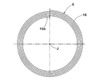
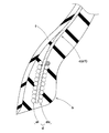
- FIG. 1 is a meridional cross-sectional view of a pneumatic tire according to an embodiment of the present invention. It is an enlarged view of the bead part of FIG. It is a side view of a bead core.
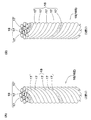
- (A) is a perspective view of Z twist bead cord
- (B) is a perspective view of S twist bead cord.
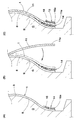
- FIG. 2 is a schematic view of an inner core and an outer core. It is a meridional sectional view of each bead part.
- (A) is an explanatory view of an inner core formation step
- (B) is an explanatory view of a carcass formation step
- (C) is an explanatory view of an outer core formation step.
- FIG. 7 is a schematic view of the inner and outer cores of another embodiment of the present invention. It is sectional drawing of the bead part of the conventional pneumatic tire.
- FIG. 1 shows a meridional cross-sectional view including a tire rotation axis of a pneumatic tire (hereinafter sometimes simply referred to as “tire”) 1 of the present embodiment.
- the tire 1 is provided with a carcass 5 extending from the tread portion 2 through the side wall portions 3 and 3 on both sides to the bead portions 4 and 4 on both sides, and bead cores 4 and 4 arranged in each bead portion 4 And six. Furthermore, the tire 1 of the present embodiment includes a belt layer 7 provided on the tire radial direction outer side of the carcass 5 and an inner liner 8 disposed on the tire radial direction inner side of the carcass 5. Such a tire 1 is used, for example, as a tire for a passenger car.
- the belt layer 7 includes one or more sheets in which belt cords are arranged at an angle of 10 to 40 degrees with respect to the tire equator C, for example, and in the present embodiment, two belt plies 7A and 7B in the tire radial direction. It is.
- the belt plies 7A and 7B are stacked in the direction in which the belt cords cross each other.
- a steel cord and, if necessary, a highly elastic organic fiber cord such as aramid and rayon are used for the belt cord of the present embodiment.
- the inner liner 8 is disposed, for example, across the bead portions 4 and 4 substantially in the entire area of the tire inner cavity surface 9 across the toroidal shape.
- the inner liner 8 is desirably excellent in air impermeability in order to maintain the internal pressure of the tire 1.
- the inner liner 8 is formed of butyl-based rubber containing 50 parts by mass or more of halogenated butyl in the rubber.
- FIG. 2 shows an enlarged view of the bead portion 4 of FIG.
- the carcass 5 is formed of, for example, one or more, in the present embodiment, one carcass ply 11 in which carcass cords of organic fibers are arranged at an angle of 70 to 90 ° with respect to the tire circumferential direction, for example.
- the carcass ply 11 extends in a toroidal shape across the bead portions 4.
- the tire radial direction inner end 11 e of the carcass ply 11 terminates in the bead core 6 without being folded back around the bead core 6.
- the bead core 6 includes an inner core 14 disposed along the tire axial inner surface 5 i of the carcass ply 11 and an outer core 15 disposed along the tire axial outer surface 5 o.
- the inner core 14 and the outer core 15 can hold the end 11 e of the carcass ply 11 from both sides, and can prevent the carcass 5 from being pulled out.
- apex rubbers 20i and 20o made of hard rubber are disposed, and the bead portion 4 is reinforced.
- chafer rubber 21 is disposed which suppresses defects such as damage due to friction with the rim and rim deviation.
- the bead cores 6 include a bead cord 16 wound at least one turn along the tire circumferential direction.
- the inner core 14 and the outer core 15 are formed by spirally winding the bead cord 16 from the inner side to the outer side in the tire radial direction around the tire axis J.
- the bead cord 16 is wound from the inner side to the outer side in the tire radial direction, whereby the inner end 16a in the tire radial direction is fixed.
- each of the inner core 14 and the outer core 15 in the present embodiment is formed in a row in the tire axial direction.
- the inner core 14 and / or the outer core 15 may be formed, for example, in two rows in the tire axial direction in order to increase the bead stiffness.
- the bead cord 16 includes the outermost layer 18 in which a plurality of filaments 17 are twisted.
- the bead cord 16 of the present embodiment has a twist structure including a core 19 including at least one filament 17 and the outermost layer 18 disposed outside thereof.
- the core 19 of the present embodiment is configured by twisting three filaments 17.
- the outermost layer 18 in the present embodiment is configured by twisting eight filaments 17.
- Each filament 17 is desirably made of, for example, steel in order to obtain high strength.
- the bead cord 16 is, for example, a bundle twist (1 ⁇ n) in which n filaments 17 are bundled and twisted, the core 19 and the outermost layer 18
- Various twisting structures may be adopted such as slush twisting in which the twisting direction and twisting pitch are the same, and double twist (m ⁇ n) in which m strands of the n filaments 17 are first twisted.
- FIG. 4A shows a Z-twisted bead cord 16Z in which the outermost layer 18 is Z-twisted.
- the “Z twist” is a twist direction in which the direction of the oblique line from the upper right to the lower left of the letter “Z” matches the direction of the spiral appearing in the outermost layer 18 in a plan view of the bead cord 16.
- FIG. 4 (B) shows an S-twisted bead cord 16S in which the outermost layer 18 is S-twisted.
- “S twist” is a twist direction in which the direction of the oblique line from the upper left to the lower right of the letter “S” matches the direction of the spiral appearing in the outermost layer 18 in a plan view of the bead cord 16.
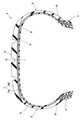
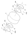
- the inner core 14 and the outer core 15 which are incorporated into the pneumatic tire 1 are conceptually shown in FIG.
- the code G indicates a core.
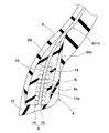
- the carcass ply 11 of the outermost layer 18 of the bead cord 16 of the inner core 14 and the outer core 15 has an inner core 14 and an outer side. It is set to be easy to move to the outer side in the tire radial direction from between the core 15. That is, since the bead cords 16 of the outermost layers of the inner core 14 and the outer core 15 are configured to be easily deformed by the twisting back Y, the carcass ply 11 is easily moved to the outer side in the tire radial direction.
- the carcass ply 11 can move outward between the inner core 14 and the outer core 15 in the tire radial direction. Therefore, an excessive increase in cord tension of the carcass cord 10 is prevented. This suppresses biting of the carcass cords 10 into the inner liner 8 and improves the durability of the tire 1.
- the inner core 14 and the outer core 15 are configured symmetrically to each other. Therefore, the inner core 14 and the outer core 15 can hold the carcass ply 11 evenly, and the holding performance of the carcass ply 11 is excellent.
- the inner core 14 and the outer core 15 have the same winding direction along the tire circumferential direction of the bead cord 16.
- the twisting direction of the outermost layer 18 of the bead cord 16 of the inner core 14 is opposite to the twisting direction of the outermost layer 18 of the bead cord 16 of the outer core 15.
- the core G is rotated clockwise of the tire axial center J when viewed from the one bead portion 4a side (the front side of FIG. 5).
- the bead cords 16 of the inner core 14 and the outer core 15 spirally wound there are wound counterclockwise in the tire circumferential direction.
- the inner core 14 in one bead portion 4a, is formed of S-twist bead cords 16S, and the outer core 15 is formed of Z-twist bead cords 16Z.
- the inner core 14 is formed of Z-twist bead cords 16Z, and the outer core 15 is formed of S-twist bead cords 16S.
- FIG. 6 shows a meridional cross-sectional view of each bead portion 4a, 4b.
- the heat shrinkage of the carcass cord 10 is preferably 1.5% or more, more preferably 2.0% or more.
- a carcass cord 10 is formed of relatively inexpensive, for example, PET, nylon or the like, and contributes to cost productivity.
- the “heat shrinkage rate” means the ratio (y / x) between the shrinkage amount y when left at 180 ° C. for 5 minutes and the length x before leaving in the unloaded state of the carcass cord 10 It is defined by (%).
- the core G may be rotated counterclockwise of the tire axis J.
- the bead cords 16 of the cores 14 and 15 attached thereto and spirally wound are wound clockwise in the tire circumferential direction.
- bead cords 16 having a twist opposite to that shown in FIG. 5 are used for each of the cores 14 and 15 of each bead portion 4.
- the inner core 14 and the outer core 15 are easy to form the green tire 1 because the bead cords 16 are spirally wound in the same direction.
- the pneumatic tire 1 comprises a green tire forming step of forming a green tire t by sequentially attaching an unvulcanized tire constituent member on the tire forming surface g of the core G; And a vulcanizing step of vulcanizing and molding by charging into a vulcanizing mold.
- the green tire forming process includes an inner core forming process S1, a carcass forming process S2, and an outer core forming process S3.
- the inner core 14 is formed on the tire forming surface g of the core G.
- the inner core 14 is formed by spirally rolling an unvulcanized rubber-coated rubberized bead cord 16 around the tire axial center J from the radially inner side to the outer side. At this time, the tire radial direction inner end 16 a of the bead cord 16 is fixed by the bead cord 16 wound on the outer side in the tire radial direction.
- the radially inner end 11e of the carcass ply 11 is rolled down inward in the tire radial direction, and is affixed to the axially outer side of the inner core 14.
- the outer core 15 is formed on the axially outer side of the inner end 11e of the carcass ply 11 in the tire axial direction.
- the outer core 15 is formed by spirally winding a rubberized bead cord 16 around the tire axial center J from the radially inner side to the outer side.
- the tire radial direction inner end 16 a of the bead cord 16 is fixed by the bead cord 16 wound on the outer side in the tire radial direction.
- the S-twisted bead cord 16S is adopted as the inner core 14 in one bead portion 4a (the front side in FIG. 5).
- One end of the S twist bead cord 16S is fixed to the core side. Since the core G is rotated clockwise with respect to the tire axial center J, the S-twisted bead cord is wound counterclockwise in the tire circumferential direction at one bead portion 4a.
- the Z-twisted bead cord 16 Z is adopted for the outer core 15. One end of the Z twist bead cord 16Z is fixed to the core side.
- the Z-twisted bead cord 16Z is also wound counterclockwise in the tire circumferential direction. Further, in the other bead portion 4b (the heel side in FIG. 5), the Z twist bead cord 16Z as the inner core 14 and the S twist bead cord 16S as the outer core 15 are respectively wound counterclockwise.
- an inner core 14 and an outer core 15 of another embodiment of the present invention are shown together with a core G in FIG.
- the inner core 14 and the outer core 15 have the same twisting direction of the outermost layer 18 of the bead cord 16.
- S-twisted bead cords 16S are used for the inner core 14 and the outer core 15, respectively.
- the winding direction of the bead cord 16 of the inner core 14 along the tire circumferential direction is opposite to the winding direction of the bead cord 16 of the outer core 15 along the tire circumferential direction.
- S-twisted bead cords 16S are used for the inner core 14 and the outer core 15 of each bead portion 4a, 4b.
- the inner core 14 in one bead portion 4a (the front side in FIG. 8), the inner core 14 is wound in a counterclockwise spiral shape, and the outer core 15 is wound in a clockwise spiral shape.
- the inner core 14 is wound in a clockwise spiral, and the outer core 15 is wound in a counterclockwise spiral.
- Z-twisted bead cords 16Z may be used for the inner core 14 and the outer core 15 of each bead portion 4a, 4b.
- the inner core 14 and the outer core 15 of each bead portion 4a, 4b are respectively spirally wound in the direction opposite to the direction shown in FIG.
- the inner core 14 and the outer core 15 are formed of bead cords 16 of either S-twist bead cord 16S or Z-twist bead cord 16Z.
- Such inner core 14 and outer core 15 help the productivity of the bead cord 16.
- a pneumatic tire (225 / 40R18) having the internal structure shown in FIG. 1 was manufactured by a core molding method.
- the bead structure of each sample tire is as shown in Table 1.
- Table 1 For each sample tire, the amount of penetration of the carcass cord into the inner liner and the durability performance were tested.
- the structures of the bead core on one side of the tire equator and the bead core on the other side of each tire are as shown in Table 1.
- the bead cords in Table 1 have a twist structure (2/7 ⁇ 0.37), a cord diameter of 1.41 mm, a twist pitch of 50 mm, and are the same except for the twist direction.
- PET is a cord of 1670/2 dtex
- rayon is a 1840/2 dtex
- aramid is a cord of 1100/2 dtex.
Landscapes
- Engineering & Computer Science (AREA)
- Mechanical Engineering (AREA)
- Tires In General (AREA)
Priority Applications (3)
| Application Number | Priority Date | Filing Date | Title |
|---|---|---|---|
| CN201480023255.8A CN105142936B (zh) | 2013-05-07 | 2014-03-11 | 充气轮胎 |
| EP14794067.0A EP2987657B1 (de) | 2013-05-07 | 2014-03-11 | Luftreifen |
| US14/785,250 US10112445B2 (en) | 2013-05-07 | 2014-03-11 | Pneumatic tire |
Applications Claiming Priority (2)
| Application Number | Priority Date | Filing Date | Title |
|---|---|---|---|
| JP2013-097799 | 2013-05-07 | ||
| JP2013097799A JP5973955B2 (ja) | 2013-05-07 | 2013-05-07 | 空気入りタイヤ |
Publications (1)
| Publication Number | Publication Date |
|---|---|
| WO2014181579A1 true WO2014181579A1 (ja) | 2014-11-13 |
Family
ID=51867065
Family Applications (1)
| Application Number | Title | Priority Date | Filing Date |
|---|---|---|---|
| PCT/JP2014/056342 Ceased WO2014181579A1 (ja) | 2013-05-07 | 2014-03-11 | 空気入りタイヤ |
Country Status (5)
| Country | Link |
|---|---|
| US (1) | US10112445B2 (de) |
| EP (1) | EP2987657B1 (de) |
| JP (1) | JP5973955B2 (de) |
| CN (1) | CN105142936B (de) |
| WO (1) | WO2014181579A1 (de) |
Families Citing this family (5)
| Publication number | Priority date | Publication date | Assignee | Title |
|---|---|---|---|---|
| KR101775321B1 (ko) * | 2016-03-17 | 2017-09-06 | 한국타이어 주식회사 | 비드부 강성을 강화한 공기압 타이어 |
| JP6848262B2 (ja) * | 2016-08-22 | 2021-03-24 | 住友ゴム工業株式会社 | 空気入りタイヤ |
| JP7245632B2 (ja) * | 2018-10-31 | 2023-03-24 | 株式会社ブリヂストン | タイヤ |
| JP7132172B2 (ja) * | 2019-05-07 | 2022-09-06 | 株式会社ブリヂストン | 空気入りタイヤ |
| JP7010356B1 (ja) * | 2020-12-07 | 2022-02-10 | 横浜ゴム株式会社 | 空気入りタイヤ |
Citations (4)
| Publication number | Priority date | Publication date | Assignee | Title |
|---|---|---|---|---|
| JP2008013135A (ja) * | 2006-07-07 | 2008-01-24 | Yokohama Rubber Co Ltd:The | 空気入りタイヤ |
| JP2008273435A (ja) * | 2007-05-01 | 2008-11-13 | Bridgestone Corp | 空気入りタイヤ |
| JP2012106441A (ja) * | 2010-11-18 | 2012-06-07 | Sumitomo Rubber Ind Ltd | 空気入りタイヤの製造方法 |
| JP2012158064A (ja) | 2011-01-31 | 2012-08-23 | Sumitomo Rubber Ind Ltd | 空気入りタイヤの製造方法 |
Family Cites Families (10)
| Publication number | Priority date | Publication date | Assignee | Title |
|---|---|---|---|---|
| JPS5975804A (ja) * | 1982-10-21 | 1984-04-28 | Bridgestone Corp | 高耐久性ラジアルタイヤ |
| JP3777241B2 (ja) * | 1997-05-06 | 2006-05-24 | 横浜ゴム株式会社 | 空気入りラジアルタイヤ |
| JP2001097010A (ja) * | 1999-09-30 | 2001-04-10 | Bridgestone Corp | 空気入りタイヤ |
| JP2006044339A (ja) * | 2004-08-02 | 2006-02-16 | Yokohama Rubber Co Ltd:The | 空気入りラジアルタイヤ |
| FR2879500A1 (fr) * | 2004-12-22 | 2006-06-23 | Michelin Soc Tech | Procede et dispositif pour la fabrication et la pose d'un renforcement circonferentiel pour pneumatique et pneumatique obtenu par ledit procede |
| JP4312173B2 (ja) * | 2005-05-24 | 2009-08-12 | 住友ゴム工業株式会社 | 自動二輪車用空気入りタイヤ |
| JP2010115957A (ja) * | 2008-11-11 | 2010-05-27 | Bridgestone Corp | 空気入りタイヤのビード部構造 |
| JP5227392B2 (ja) * | 2010-12-16 | 2013-07-03 | 住友ゴム工業株式会社 | 空気入りタイヤ及び空気入りタイヤの製造方法 |
| JP2013082143A (ja) | 2011-10-11 | 2013-05-09 | Sumitomo Rubber Ind Ltd | 空気入りタイヤの製造方法、及びそれによって形成された空気入りタイヤ |
| JP6074230B2 (ja) * | 2012-11-09 | 2017-02-01 | 住友ゴム工業株式会社 | 空気入りタイヤ、及びその製造方法 |
-
2013
- 2013-05-07 JP JP2013097799A patent/JP5973955B2/ja not_active Expired - Fee Related
-
2014
- 2014-03-11 WO PCT/JP2014/056342 patent/WO2014181579A1/ja not_active Ceased
- 2014-03-11 EP EP14794067.0A patent/EP2987657B1/de active Active
- 2014-03-11 CN CN201480023255.8A patent/CN105142936B/zh active Active
- 2014-03-11 US US14/785,250 patent/US10112445B2/en not_active Expired - Fee Related
Patent Citations (4)
| Publication number | Priority date | Publication date | Assignee | Title |
|---|---|---|---|---|
| JP2008013135A (ja) * | 2006-07-07 | 2008-01-24 | Yokohama Rubber Co Ltd:The | 空気入りタイヤ |
| JP2008273435A (ja) * | 2007-05-01 | 2008-11-13 | Bridgestone Corp | 空気入りタイヤ |
| JP2012106441A (ja) * | 2010-11-18 | 2012-06-07 | Sumitomo Rubber Ind Ltd | 空気入りタイヤの製造方法 |
| JP2012158064A (ja) | 2011-01-31 | 2012-08-23 | Sumitomo Rubber Ind Ltd | 空気入りタイヤの製造方法 |
Also Published As
| Publication number | Publication date |
|---|---|
| US20160082784A1 (en) | 2016-03-24 |
| EP2987657A4 (de) | 2016-12-28 |
| CN105142936B (zh) | 2017-03-08 |
| JP5973955B2 (ja) | 2016-08-23 |
| EP2987657A1 (de) | 2016-02-24 |
| JP2014218131A (ja) | 2014-11-20 |
| CN105142936A (zh) | 2015-12-09 |
| US10112445B2 (en) | 2018-10-30 |
| EP2987657B1 (de) | 2018-03-07 |
Similar Documents
| Publication | Publication Date | Title |
|---|---|---|
| US8104525B2 (en) | Pneumatic tire | |
| US20090107605A1 (en) | Pneumatic tire and method for producing same | |
| US20110083782A1 (en) | Pneumatic tire | |
| JP5775592B2 (ja) | 空気入りタイヤの製造方法及び空気入りタイヤ | |
| WO2014181579A1 (ja) | 空気入りタイヤ | |
| CN110023101A (zh) | 充气轮胎 | |
| WO2009091066A1 (ja) | 空気入りラジアルタイヤ | |
| US20170100964A1 (en) | Pneumatic tire, and pneumatic tire production method | |
| CN108274959B (zh) | 充气轮胎及其生产方法 | |
| JP5384255B2 (ja) | 空気入りタイヤ | |
| JP5355067B2 (ja) | 空気入りタイヤおよびその製造方法 | |
| JP6374832B2 (ja) | 空気入りタイヤ | |
| JP3777241B2 (ja) | 空気入りラジアルタイヤ | |
| JP5305389B2 (ja) | 空気入りラジアルタイヤ | |
| JP2015212109A (ja) | 空気入りタイヤ | |
| JP6235859B2 (ja) | 空気入りタイヤの製造方法及びバンドストリップ | |
| JP5294405B2 (ja) | 空気入りラジアルタイヤ | |
| JP2014117978A (ja) | ビードコア、それを用いた空気タイヤ、及び空気入りタイヤの製造方法 | |
| JP2017001673A (ja) | 空気入りタイヤ、及びその製造方法 | |
| JP2014201136A (ja) | 空気入りタイヤ | |
| JP2006044339A (ja) | 空気入りラジアルタイヤ | |
| JP6805755B2 (ja) | 空気入りタイヤ | |
| JPH06297906A (ja) | 空気入りラジアルタイヤ | |
| JP2005041396A (ja) | 空気入りラジアルタイヤ及びその製造方法 | |
| JP2011230584A (ja) | 自動二輪車用空気入りラジアルタイヤ |
Legal Events
| Date | Code | Title | Description |
|---|---|---|---|
| WWE | Wipo information: entry into national phase |
Ref document number: 201480023255.8 Country of ref document: CN |
|
| 121 | Ep: the epo has been informed by wipo that ep was designated in this application |
Ref document number: 14794067 Country of ref document: EP Kind code of ref document: A1 |
|
| WWE | Wipo information: entry into national phase |
Ref document number: 14785250 Country of ref document: US |
|
| NENP | Non-entry into the national phase |
Ref country code: DE |
|
| WWE | Wipo information: entry into national phase |
Ref document number: 2014794067 Country of ref document: EP |