WO2014184945A1 - 無段変速機 - Google Patents
無段変速機 Download PDFInfo
- Publication number
- WO2014184945A1 WO2014184945A1 PCT/JP2013/063766 JP2013063766W WO2014184945A1 WO 2014184945 A1 WO2014184945 A1 WO 2014184945A1 JP 2013063766 W JP2013063766 W JP 2013063766W WO 2014184945 A1 WO2014184945 A1 WO 2014184945A1
- Authority
- WO
- WIPO (PCT)
- Prior art keywords
- continuously variable
- variable transmission
- metal element
- fluid
- sheave
- Prior art date
- Legal status (The legal status is an assumption and is not a legal conclusion. Google has not performed a legal analysis and makes no representation as to the accuracy of the status listed.)
- Ceased
Links
Images





Classifications
-
- F—MECHANICAL ENGINEERING; LIGHTING; HEATING; WEAPONS; BLASTING
- F16—ENGINEERING ELEMENTS AND UNITS; GENERAL MEASURES FOR PRODUCING AND MAINTAINING EFFECTIVE FUNCTIONING OF MACHINES OR INSTALLATIONS; THERMAL INSULATION IN GENERAL
- F16H—GEARING
- F16H9/00—Gearings for conveying rotary motion with variable gear ratio, or for reversing rotary motion, by endless flexible members
- F16H9/02—Gearings for conveying rotary motion with variable gear ratio, or for reversing rotary motion, by endless flexible members without members having orbital motion
- F16H9/04—Gearings for conveying rotary motion with variable gear ratio, or for reversing rotary motion, by endless flexible members without members having orbital motion using belts, V-belts, or ropes
- F16H9/12—Gearings for conveying rotary motion with variable gear ratio, or for reversing rotary motion, by endless flexible members without members having orbital motion using belts, V-belts, or ropes engaging a pulley built-up out of relatively axially-adjustable parts in which the belt engages the opposite flanges of the pulley directly without interposed belt-supporting members
- F16H9/16—Gearings for conveying rotary motion with variable gear ratio, or for reversing rotary motion, by endless flexible members without members having orbital motion using belts, V-belts, or ropes engaging a pulley built-up out of relatively axially-adjustable parts in which the belt engages the opposite flanges of the pulley directly without interposed belt-supporting members using two pulleys, both built-up out of adjustable conical parts
- F16H9/18—Gearings for conveying rotary motion with variable gear ratio, or for reversing rotary motion, by endless flexible members without members having orbital motion using belts, V-belts, or ropes engaging a pulley built-up out of relatively axially-adjustable parts in which the belt engages the opposite flanges of the pulley directly without interposed belt-supporting members using two pulleys, both built-up out of adjustable conical parts only one flange of each pulley being adjustable
-
- F—MECHANICAL ENGINEERING; LIGHTING; HEATING; WEAPONS; BLASTING
- F16—ENGINEERING ELEMENTS AND UNITS; GENERAL MEASURES FOR PRODUCING AND MAINTAINING EFFECTIVE FUNCTIONING OF MACHINES OR INSTALLATIONS; THERMAL INSULATION IN GENERAL
- F16G—BELTS, CABLES, OR ROPES, PREDOMINANTLY USED FOR DRIVING PURPOSES; CHAINS; FITTINGS PREDOMINANTLY USED THEREFOR
- F16G5/00—V-belts, i.e. belts of tapered cross-section
- F16G5/16—V-belts, i.e. belts of tapered cross-section consisting of several parts
-
- F—MECHANICAL ENGINEERING; LIGHTING; HEATING; WEAPONS; BLASTING
- F16—ENGINEERING ELEMENTS AND UNITS; GENERAL MEASURES FOR PRODUCING AND MAINTAINING EFFECTIVE FUNCTIONING OF MACHINES OR INSTALLATIONS; THERMAL INSULATION IN GENERAL
- F16H—GEARING
- F16H57/00—General details of gearing
- F16H57/04—Features relating to lubrication or cooling or heating
- F16H57/0458—Oil-mist or spray lubrication; Means to reduce foam formation
- F16H57/046—Oil-mist or spray lubrication
-
- F—MECHANICAL ENGINEERING; LIGHTING; HEATING; WEAPONS; BLASTING
- F16—ENGINEERING ELEMENTS AND UNITS; GENERAL MEASURES FOR PRODUCING AND MAINTAINING EFFECTIVE FUNCTIONING OF MACHINES OR INSTALLATIONS; THERMAL INSULATION IN GENERAL
- F16H—GEARING
- F16H57/00—General details of gearing
- F16H57/04—Features relating to lubrication or cooling or heating
- F16H57/048—Type of gearings to be lubricated, cooled or heated
- F16H57/0487—Friction gearings
- F16H57/0489—Friction gearings with endless flexible members, e.g. belt CVTs
Definitions
- the present invention relates to a continuously variable transmission including a continuously variable transmission belt in which a plurality of metal elements are annularly supported.
- a continuously variable transmission belt 100 in which a plurality of metal elements 101 are stacked and supported by an endless ring 102 is used as a driving sheave KS and a driven sheave JS. It is wrapped around.
- Each of the driving sheave KS and the driven sheave JS includes a conical plate-shaped fixed sheave and a movable sheave.
- each movable sheave moves in the directions of the axes J1 and J2, and the rotation radius of the wound continuously variable transmission belt 100 is changed to change continuously from high speed to low speed. is doing.
- the applicant of the present invention has described that the continuously variable transmission belt 100 moves continuously from the driven sheave JS to the driving sheave KS so as to close the gap in the stacking direction of the metal elements 101.
- a technique of blowing air in the moving direction of the transmission belt 100 is disclosed (see Patent Document 1).
- Patent Document 1 has the following problems. That is, even if air is blown in the moving direction of the continuously variable transmission belt 100 so as to close the gap in the stacking direction of the metal elements 101, the outer shape of each metal element 101 is the same, and between the metal elements 101. Since the gap is very small, there is a problem that the blown air hardly acts on the metal element 101 effectively. Further, at the location KD where the continuously variable transmission belt 100 is wound around the driving sheave KS, the moving speed of the head portion 111 located on the outer peripheral side in the metal element 101 is set to the movement of the body portion 112 located on the inner peripheral side. If it is not larger than the speed, there is a problem that the gap in the stacking direction of the metal elements 101 cannot be closed.
- the present invention has been made to solve the above-described problems.
- the continuously variable transmission belt is wound around the driving sheave, the posture of the metal element is effectively controlled, and the continuously variable transmission is
- An object of the present invention is to provide a continuously variable transmission capable of improving the transmission efficiency of driving force.
- a continuously variable transmission includes a continuously variable transmission belt in which a plurality of metal elements are stacked and supported on an endless ring as a driving sheave and a driven sheave.
- a flange portion or a groove portion is formed, and while the continuously variable transmission belt moves from the driven sheave to the driving sheave, fluid is directed toward the flange portion or the groove portion of the continuously variable transmission belt.
- a fluid supply device for spraying in the moving direction is provided.
- At least one of the metal elements is formed with a flange or a groove on the outer peripheral portion located on the outer peripheral side and / or the inner peripheral portion located on the inner peripheral side with respect to the endless ring, Since the continuously variable transmission belt moves from the driven sheave to the driving sheave, the fluid supply device that blows the fluid in the moving direction of the continuously variable transmission belt toward the flange or the groove is provided. The fluid sprayed from the supply device acts directly on the flange or groove formed on the outer periphery and / or inner periphery of the metal element to effectively control the posture of the metal elements stacked in the moving direction. Can do.
- the gap in the stacking direction of the metal elements can be reliably reduced.
- the occurrence of slip between the metal element and the driving sheave can be prevented, and the transmission efficiency of the driving force in the continuously variable transmission can be improved.
- the metal element having the flange or the groove is provided in a plurality and disposed at a predetermined interval in the stacking direction, the fluid sprayed from the fluid supply device is formed on the metal element. It can act periodically on the groove. Therefore, gaps in the stacking direction between the metal elements can be periodically filled. As a result, the attitude of the metal elements can be controlled more effectively, and the gap in the stacking direction between the metal elements can be more reliably reduced.
- the fluid supply device includes the first jet port directed to the flange portion or the groove portion formed in the outer peripheral portion, and the second jet port directed to the flange portion or the groove portion formed in the inner peripheral portion, Since the jet power of the fluid sprayed from the first jet nozzle is larger than the jet power of the fluid jetted from the second jet nozzle, the fluid sprayed from the fluid supply device has an inner circumference in the flange or groove formed on the outer circumference of the metal element. It can act more strongly than the collar or groove formed in the part. Therefore, the outer peripheral side in the metal element laminated
- the moving speed on the outer peripheral side of the metal element can be made larger than the moving speed on the inner peripheral side, and the gap between the metal elements in the stacking direction can be increased. Can be further packed. Therefore, the occurrence of slip between the metal element and the drive sheave can be prevented, and the transmission efficiency of the driving force in the continuously variable transmission can be further improved.
- the plate thickness of the metal element in which the flange portion or the groove portion is formed is larger than the plate thickness of other metal elements. preferable.
- the fluid sprayed from a fluid supply apparatus applied to the collar part or groove part formed in the metal element can act more effectively. Specifically, by increasing the plate thickness of the metal element that forms the flange portion than the plate thickness of the other metal elements, the inertial force of the metal element extruded by the fluid is increased, and the fluid is sprayed from the position. The posture of the front metal element group can be kept stable until it is wound around the drive sheave.
- the plate thickness of the metal element in which the groove portion is formed is made larger than the plate thickness of other metal elements, so that the interval between the metal elements stacked before and after the metal element in which the groove portion is formed is expanded, so that the fluid The fluid sprayed from the supply device can easily enter the gap, and the pushing force of the metal element can be increased. As a result, the attitude of the metal element can be more effectively controlled.
- the fluid sprayed from the fluid supply device is lubricating oil of the continuously variable transmission.
- the fluid sprayed from the fluid supply device is the lubricating oil of the continuously variable transmission, it is less likely to diffuse from the jet port compared to air, and the directivity is improved. It can be made to act on a part or a groove part intensively. Therefore, it is possible to reliably transmit the fluid jet power to the metal element. Further, since the lubricating oil has a larger mass and a larger momentum than air, the pushing force of the metal element can be improved. Furthermore, the fluid supply device can also be used as a lubricating oil supply device for a continuously variable transmission. As a result, in the continuously variable transmission, without providing a new lubricating oil supply device, it is possible to prevent slippage between the metal element and the drive sheave and to improve the transmission efficiency of the driving force in the continuously variable transmission. Can be further improved.
- the continuously variable transmission belt when the continuously variable transmission belt is wound around the drive sheave, the continuously variable transmission can effectively improve the transmission efficiency of the driving force by effectively controlling the attitude of the metal element. Can be provided.
- FIG. 1 is a schematic side view of a continuously variable transmission according to an embodiment.
- FIG. 2 is a partial perspective view of the continuously variable transmission belt shown in FIG. It is a front view of one metal element (what formed the collar part in the head part and the trunk
- continuously variable transmission according to this embodiment will be described in detail with reference to the drawings.
- the overall structure of the continuously variable transmission will be described, and then the detailed structures of the continuously variable transmission belt and the metal element will be described. Thereafter, a method for controlling the posture of the metal element by spraying a fluid on the flange or groove of the metal element will be described.
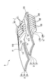
- FIG. 1 shows a schematic side view of a continuously variable transmission according to the present embodiment.
- a continuously variable transmission 10 includes a driving sheave KS, a driven sheave JS, a continuously variable transmission belt 3, and a fluid supply device 4 (4a, 4b). It has.
- Each of the driving sheave KS and the driven sheave JS includes a conical plate-shaped fixed sheave and a movable sheave, and the shafts J1 and J2 are spaced apart from each other.
- the continuously variable transmission 10 shifts continuously from high speed to low speed by moving the movable sheaves in the directions of the axes J1 and J2 and changing the rotation radius of the wound continuously variable transmission belt 3. is doing.
- the continuously variable transmission belt 3 is a push-type belt, there is no gap between the metal elements 1 when moving from the driving sheave KS to the driven sheave JS (direction of arrow FF).
- a slight gap for example, about 0.5 to 0.8 mm as a whole
- the fluid supply device 4 (4a, 4b) closes the gap between the metal elements 1 while the continuously variable transmission belt 3 moves from the driven sheave JS in the direction of the driving sheave KS (direction of arrow FB).
- an ejection port 4 a that ejects liquid (lubricating oil) toward the head portion 11 of the metal element 1 and an ejection port 4 b that ejects liquid (lubricating oil) toward the body portion 12 of the metal element 1 are provided.
- the jet nozzle 4a and the jet nozzle 4b are arrange
- a difference in jetting power or jetting speed of the liquid (lubricating oil) ejected from the jetting port 4a is made different by making the jetting amount or jetting speed of the liquid (lubricating oil) jetted from the jetting port 4b larger than the jetting amount or jetting speed of the liquid (lubricating oil) jetted from the jetting port 4b.
- FIG. 2 is a partial perspective view of the continuously variable transmission belt shown in FIG.
- FIG. 3 shows a front view of one of the metal elements shown in FIG. 1 (having a collar on the head and the body).
- FIG. 4 shows a front view of the other metal element shown in FIG. 1 (that does not form a collar on the head and the body).
- FIG. 5 is a front view showing a shape variation of one metal element shown in FIG.
- the continuously variable transmission belt 3 includes two types of metal elements 1 (1 a and 1 b) and an endless ring 2.
- one metal element 1a is arranged with a predetermined interval in the stacking direction between the other metal element 1b.
- one metal element 1a is repeatedly arranged each time three other metal elements 1b are laminated, but the number is not necessarily limited to three.
- a plurality of one metal elements 1a may be stacked and then a plurality of the other metal elements 1b may be stacked and arranged at a predetermined interval in the stacking direction therebetween.
- the detailed structure of one metal element 1a and the other metal element 1b will be described later.
- the two types of metal elements 1 (1a, 1b) each have a substantially triangular head portion 11, a substantially rectangular body portion 12 and a neck portion 13, and the head portion 11 and the body portion 12 are connected to the neck portion 13. It is the plate-shaped body formed by connecting with.
- the head portion 11 corresponds to an “outer peripheral portion” described in the claims
- the body portion 12 corresponds to an “inner peripheral portion” described in the claims.
- the body portion 12 includes a thick portion 123 having a large plate thickness and a thin portion 124 that is formed below the thick portion 123 and gradually decreases in thickness toward the bottom.
- Inclined surfaces that incline downward and inward are formed at both left and right ends of the body portion 12.
- the inclined surface constitutes a driving force transmitting portion 122 that transmits the driving force by frictional contact with the conical wall surfaces of the driving sheave KS and the driven sheave JS.
- a ring holding groove 111 for inserting the endless ring 2 with the neck portion 13 interposed therebetween is formed between the head portion 11 and the body portion 12.
- a saddle portion 121 with which the inner peripheral surface of the endless ring 3 abuts is formed at the lower end of the ring holding groove 111.
- the saddle portion 121 is formed in parallel with the upper end of the body portion 12.
- a convex portion 112 is formed at the center of the front end of the head 11, and a concave portion 113 (not shown) is formed at the center of the rear end. In the adjacent metal elements 1, the convex portion 112 and the concave portion 113 are fitted together, thereby preventing vertical and horizontal misalignment.
- a steel material that can be heat-treated and has excellent wear resistance for example, carbon tool steel (SK material) can be used.
- the thickness of the metal element 1 is about 1 to 2 mm.
- the endless ring 2 shows a structure in which three ring bodies 21 are laminated, but the number of the ring bodies 21 laminated is not limited to this, and may be nine or twelve, for example.
- the endless ring 2 can be made of a steel material that can be heat-treated and has excellent tensile strength and wear resistance, such as maraging steel.
- the thickness of the ring body 31 is about 150 to 200 ⁇ m.
- one of the metal elements 1 a includes a first head 11 that protrudes outward from the head 11 positioned on the outer peripheral side with respect to the endless ring 2.
- a collar portion (shaded portion) 113a is formed.
- the first collar portion (shaded portion) 113a protrudes outward in a circular arc shape from the symmetrically inclined side (imaginary line) 114a of the head portion 11.
- a second flange portion (shaded portion) 124 a that protrudes to the inner peripheral side is formed on the body portion 11 that is positioned on the inner peripheral side with respect to the endless ring 2.
- the second flange portion (shaded portion) 124a protrudes outward in a crescent shape from a symmetrical arc side (imaginary line) 125a formed in the thin portion 124 of the body portion 12.
- the other metal element 1b is not formed with the first flange (shaded portion) 113a and the second flange (hatched portion) 124a formed on one metal element 1a.
- a symmetrical side 113 b is formed on the head 11, and a symmetrical circular arc side 124 b is formed on the body 12.
- the inclined side 113b has the same shape as the inclined side (virtual line) 114a, and the arc side 124b has the same shape as the arc side (virtual line) 125a.
- One metal element 1a and the other metal element 1b are different only in the presence or absence of the first flange portion (shaded portion) 113a and the second flange portion (shaded portion) 124a, and other structures are common to each other. Yes.
- the inclined side (imaginary line) 114a of one metal element 1a corresponds to the first groove part
- the arc side (imaginary line) 125a corresponds to the second groove part.
- the other metal element 1b is formed by the inclined side 114b (virtual line) and the arc side 125b (virtual line).
- the first hook portion (shaded portion) 113a and the second hook portion (hatched portion) 124a will be described in detail with reference to FIGS.
- the first groove portion (114a) and the second groove portion (125a) will be described in detail with reference to FIGS.
- an optimum shape is selected in order to close the gap between the metal elements 1.
- the moving speed on the outer peripheral side of the metal element 1 (1a, 1b) can be made larger than the moving speed on the inner peripheral side.
- the gap in the stacking direction between (1a, 1b) can be further reduced. As a result, it becomes easier to further reduce the slip between the metal element 1 (1a, 1b) and the driving sheave KS.
- FIG. 6 is a cross-sectional view of the continuously variable transmission belt shown in FIG. 1 when a fluid is sprayed on a collar portion formed on one metal element.
- FIG. 7 shows a cross-sectional view when the plate thickness of one metal element shown in FIG. 6 is made larger than the plate thickness of the other metal element.
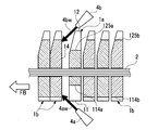
- FIG. 8 is a cross-sectional view of the continuously variable transmission belt shown in FIG. 1 when fluid is sprayed onto a groove formed in one metal element.
- FIG. 9 shows a cross-sectional view when the plate thickness of one metal element shown in FIG. 8 is made larger than the plate thickness of the other metal element.
- FIG. 10 is an explanatory diagram regarding rotation suppression of the metal element in the continuously variable transmission belt shown in FIG.
- the first flange portion 113a is formed on the head portion 11 of one metal element 1a, and the second flange portion 124a is formed on the body portion 12.
- fluid lubrication
- Oil 4aw, 4bw are sprayed in the moving direction of the continuously variable transmission belt 3.
- the 1st collar part 113a and the 2nd collar part 124a which were formed in one metal element 1a protrude outward from the inclination side 113b and the circular arc side 124b of the other metal element 1b. Therefore, the fluid (lubricating oil) 4aw and 4bw sprayed from the ejection ports 4a and 4b of the fluid supply device 4 directly act on the first flange portion 113a and the second flange portion 124a formed on one metal element 1a.
- the other metal elements 1b stacked in the moving direction can be extruded and brought into contact with each other.
- the jet nozzles 4a and 4b can also be installed in multiple places. For example, in order to perform posture control effectively and efficiently, there may be an odd number of nozzles. In that case, the degree of freedom of attitude control of the metal element 1 (1a, 1b) is expanded by closing the gap between the metal elements 1 (1a, 1b) and controlling the strength of each injection.
- the second embodiment is an example in which the plate thickness t1 of one metal element 1a in the first embodiment is larger than the plate thickness t2 of the other metal element 1b.
- Increasing the inertial force of one metal element 1a extruded by the fluid (lubricating oil) 4aw, 4bw by making the plate thickness t1 of one metal element 1a larger than the plate thickness t2 of the other metal element 1b Can do.
- the postures of the groups 1a and 1b can be kept stable.
- the first groove portion 114a is formed in the head portion 11 of one metal element 1a and the second groove portion 125a is formed in the body portion 12, and then the continuously variable transmission is used. While the belt 3 moves from the driven sheave to the driving sheave (in the direction of the arrow FB), fluid (lubricating oil) 4aw from the injection ports 4a and 4b toward the first groove 114a and the second groove 125a. This is an example in which 4 bw is sprayed in the moving direction of the continuously variable transmission belt 3.
- the first groove portion 114a and the second groove portion 125a formed in one metal element 1a are recessed inward from the inclined side 114b and the arc side 125b of the other metal element 1b. Therefore, the fluid (lubricating oil) 4aw and 4bw sprayed from the jet nozzles 4a and 4b of the fluid supply device 4 are stacked in front of one metal element 1a in which the first groove 114a and the second groove 125a are formed. Directly acting on the back surface 14 of the metal element 1b, the other metal element 1b stacked in the moving direction can be extruded and brought into contact with each other. As a result, the posture of the other metal element 1b stacked in front of the other metal element 1b sprayed with the fluid (lubricating oil) 4aw and 4bw can be effectively controlled.
- the fourth embodiment is an example in which the plate thickness t1 of one metal element 1a in the third embodiment is larger than the plate thickness t2 of the other metal element 1b. Since the distance between the other metal elements 1b stacked before and after the one metal element 1a in which the first groove part 114a and the second groove part 125a are formed is increased, the fluid sprayed from the jet outlets 4a and 4b of the fluid supply device 4 (Lubricant) 4aw and 4bw can easily enter the gap, and the pushing force of the other metal element 1b sprayed with fluid (lubricant) 4aw and 4bw can be increased. As a result, the posture of the other metal element 1b stacked forward can be controlled more effectively.
- the posture of the metal element 1 may rotate in the directions of arrows X, Y, and Z.
- the rotation in the direction of arrow X is called rolling
- the rotation in the direction of arrow Y is called pitching
- the rotation in the direction of arrow Z is called yawing.
- the jet outlets 4a and 4b are set also in the left-right direction in the fluid supply device 4 described above.
- fluid (lubricating oil) 4awR, 4awL is sprayed on the head 11 of the metal element 1 from the left and right directions, and fluid (lubricating oil) 4awR, 4awL from the left and right directions on the body portion 12.
- the metal element 1 can be prevented from rotating in the directions of the arrows X, Y, and Z, and the interference between the metal element 1 and the endless ring 2 can be prevented and the durability of each can be improved. be able to.
- the present invention can be used as a continuously variable transmission including a continuously variable transmission belt in which a plurality of metal elements are annularly supported.
Landscapes
- Engineering & Computer Science (AREA)
- General Engineering & Computer Science (AREA)
- Mechanical Engineering (AREA)
- Chemical & Material Sciences (AREA)
- Oil, Petroleum & Natural Gas (AREA)
- Transmissions By Endless Flexible Members (AREA)
Abstract
Description
はじめに、本実施形態に係る無段変速機の全体構造について、図1を用いて説明する。図1に、本実施形態に係る無段変速機の模式的側面図を示す。
次に、無段変速機用ベルト及び金属エレメントの詳細構造について、図2~図5を用いて説明する。図2に、図1に示す無段変速機用ベルトの部分斜視図を示す。図3に、図1に示す一方の金属エレメント(頭部及び胴体部に鍔部を形成したもの)の正面図を示す。図4に、図1に示す他方の金属エレメント(頭部及び胴体部に鍔部を形成しないもの)の正面図を示す。図5に、図1に示す一方の金属エレメントの形状バリエーションを表す正面図を示す。
次に金属エレメントの姿勢制御方法について、図6~図10を用いて説明する。図6に、図1に示す無段変速機用ベルトにおける一方の金属エレメントに形成した鍔部に流体を吹き付けたときの断面図を示す。図7に、図6に示す一方の金属エレメントの板厚を他方の金属エレメントの板厚より大きくしたときの断面図を示す。図8に、図1に示す無段変速機用ベルトにおける一方の金属エレメントに形成した溝部に流体を吹き付けたときの断面図を示す。図9に、図8に示す一方の金属エレメントの板厚を他方の金属エレメントの板厚より大きくしたときの断面図を示す。図10に、図1に示す無段変速機用ベルトにおける金属エレメントの回動抑制に関する説明図を示す。
図6に示すように、第1実施例は、一方の金属エレメント1aの頭部11に第1鍔部113aを形成し、胴体部12に第2鍔部124aを形成した上で、無段変速機用ベルト3が従動用シーブから駆動用シーブの方向(矢印FBの方向)へ移動する間で、第1鍔部113a及び第2鍔部124aに向けて、噴射口4a、4bから流体(潤滑油)4aw、4bwを無段変速機用ベルト3の移動方向へ吹き付ける事例である。この場合、一方の金属エレメント1aに形成した第1鍔部113a及び第2鍔部124aは、他方の金属エレメント1bの傾斜辺113b及び円弧辺124bより外方へ突出している。そのため、流体供給装置4の噴出口4a、4bから吹き付ける流体(潤滑油)4aw、4bwが、一方の金属エレメント1aに形成した第1鍔部113a及び第2鍔部124aに直接的に作用して、移動方向に積層された他方の金属エレメント1bを押出して互いに当接させることができる。その結果、流体(潤滑油)4aw、4bwを吹き付けられた一方の金属エレメント1aより前方に積層された他方の金属エレメント1bの姿勢を効果的に制御することができる。なお、更なる姿勢制御が必要な場合は、噴出口4a、4bを複数箇所で設置することもできる。例えば、姿勢制御を有効かつ効率的に行うために、噴出口が奇数個となる場合もある。その場合、金属エレメント1(1a、1b)間の隙間を詰め、更にそれぞれの噴射の強さを制御することで、金属エレメント1(1a、1b)の姿勢制御の自由度が拡大する。
図7に示すように、第2実施例は、第1実施例における一方の金属エレメント1aの板厚t1を他方の金属エレメント1bの板厚t2より大きくした事例である。一方の金属エレメント1aの板厚t1を、他の金属エレメント1bの板厚t2より大きくすることによって、流体(潤滑油)4aw、4bwによって押出される一方の金属エレメント1aの慣性力を増大させることができる。その結果、流体(潤滑油)4aw、4bwを吹き付けた位置から駆動シーブKSに巻き掛かる位置まで、流体(潤滑油)4aw、4bwを吹き付けられた一方の金属エレメント1aより前方に積層された金属エレメント1a、1b群の姿勢を安定し続けることができる。なお、板厚t1を大きくした一方の金属エレメント1aは、複数存在し、他方の金属エレメント1bの間に適当な間隔で配置されても良い。
図8に示すように、第3実施例は、一方の金属エレメント1aの頭部11に第1溝部114aを形成し、胴体部12に第2溝部125aを形成した上で、無段変速機用ベルト3が従動用シーブから駆動用シーブの方向(矢印FBの方向)へ移動する間で、第1溝部114a及び第2溝部125aに向けて、噴射口4a、4bから流体(潤滑油)4aw、4bwを無段変速機用ベルト3の移動方向へ吹き付ける事例である。この場合、一方の金属エレメント1aに形成した第1溝部114a及び第2溝部125aは、他方の金属エレメント1bの傾斜辺114b及び円弧辺125bより内方へ陥没している。そのため、流体供給装置4の噴出口4a、4bから吹き付ける流体(潤滑油)4aw、4bwが、第1溝部114a及び第2溝部125aが形成された一方の金属エレメント1aの前方に積層された他方の金属エレメント1bの背面14に直接的に作用して、移動方向に積層された他方の金属エレメント1bを押出して互いに当接させることができる。その結果、流体(潤滑油)4aw、4bwを吹き付けられた他方の金属エレメント1bより前方に積層された他方の金属エレメント1bの姿勢を効果的に制御することができる。
図9に示すように、第4実施例は、第3実施例における一方の金属エレメント1aの板厚t1を他方の金属エレメント1bの板厚t2より大きくした事例である。第1溝部114a及び第2溝部125aを形成した一方の金属エレメント1aの前後に積層された他方の金属エレメント1b同士の間隔が拡大されるので、流体供給装置4の噴出口4a、4bから吹き付ける流体(潤滑油)4aw、4bwが、その隙間に進入し易くなり、流体(潤滑油)4aw、4bwを吹き付けられた他方の金属エレメント1bの押出し力を増大させることができる。その結果、前方に積層された他方の金属エレメント1bの姿勢を、より一層効果的に制御することができる。
次に、第1実施例から第4実施例の流体供給装置4を用いて、金属エレメント1と無端リング2との干渉防止方法について説明する。前述したように、無端リング2に支持された金属エレメント1は、従動用シーブJSから駆動用シーブKSの方向へ移動するとき、金属エレメント1同士の間に僅かな隙間が生じる。そのため、図10(A)に示すように、金属エレメント1の姿勢は、矢印X、Y、Zの各方向へ回動する場合がある。一般に、矢印Xの方向への回動をローリングといい、矢印Yの方向への回動をピッチングといい、矢印Zの方向への回動をヨーイングといい、いずれの回動によっても、金属エレメント1と無端リング2とが干渉し、それぞれの耐久性が低下する。ここでは、上述した流体供給装置4に噴出口4a、4bをそれぞれ左右方向にも設定している。これによって、図10(B)に示すように、金属エレメント1の頭部11に左右方向から流体(潤滑油)4awR、4awLを吹き付け、胴体部12に左右方向から流体(潤滑油)4awR、4awLを吹き付けることができる。その結果、金属エレメント1が矢印X、Y、Zの各方向へ回動するのを抑制することができ、金属エレメント1と無端リング2との干渉を防止して、それぞれの耐久性を向上させることができる。
2 無端リング
3 無段変速機用ベルト
4 流体供給装置
4a、4b 流体供給装置の噴出口
10 無段変速機
11 頭部(外周部)
12 胴体部(内周部)
13 首部
14 背面
113a 第1鍔部
124a 第2鍔部
114a 第1溝部
125a 第2溝部
KS 駆動用シーブ
JS 従動用シーブ
Claims (5)
- 複数の金属エレメントが無端リングに積層支持された無段変速機用ベルトを駆動用シーブ及び従動用シーブに巻き掛けてなる無段変速機であって、
前記金属エレメントの内、少なくとも1個には、前記無端リングに対して外周側に位置する外周部及び/又は内周側に位置する内周部に鍔部又は溝部を形成し、
前記無段変速機用ベルトが前記従動用シーブから前記駆動用シーブへ移動する間で、前記鍔部又は溝部に向けて、流体を前記無段変速機用ベルトの移動方向へ吹き付ける流体供給装置を備えたことを特徴とする無段変速機。 - 請求項1に記載された無段変速機であって、
前記鍔部又は溝部を形成した前記金属エレメントは、複数個備え、積層方向で所定の間隔をあけて配置したことを特徴とする無段変速機。 - 請求項1又は請求項2に記載された無段変速機であって、
前記流体供給装置は、前記外周部に形成した前記鍔部又は溝部に向けた第1噴出口と、前記内周部に形成した前記鍔部又は溝部に向けた第2噴出口とを備え、
前記第1噴出口から吹き付ける流体の噴出力が、前記第2噴出口から吹き付ける流体の噴出力より大きいことを特徴とする無段変速機。 - 請求項1乃至請求項3に記載された無段変速機であって、
前記鍔部又は溝部を形成した前記金属エレメントの板厚を、他の金属エレメントの板厚より大きくしたことを特徴とする無段変速機。 - 請求項1乃至請求項4に記載された無段変速機であって、
前記流体供給装置から吹き付ける流体は、前記無段変速機の潤滑油であることを特徴とする無段変速機。
Priority Applications (5)
| Application Number | Priority Date | Filing Date | Title |
|---|---|---|---|
| PCT/JP2013/063766 WO2014184945A1 (ja) | 2013-05-17 | 2013-05-17 | 無段変速機 |
| EP13884614.2A EP2998614B1 (en) | 2013-05-17 | 2013-05-17 | Continuously variable transmission |
| US14/783,305 US9746056B2 (en) | 2013-05-17 | 2013-05-17 | Continuously variable transmission |
| CN201380076604.8A CN105209788B (zh) | 2013-05-17 | 2013-05-17 | 无级变速器 |
| JP2015516853A JP6061028B2 (ja) | 2013-05-17 | 2013-05-17 | 無段変速機 |
Applications Claiming Priority (1)
| Application Number | Priority Date | Filing Date | Title |
|---|---|---|---|
| PCT/JP2013/063766 WO2014184945A1 (ja) | 2013-05-17 | 2013-05-17 | 無段変速機 |
Publications (1)
| Publication Number | Publication Date |
|---|---|
| WO2014184945A1 true WO2014184945A1 (ja) | 2014-11-20 |
Family
ID=51897950
Family Applications (1)
| Application Number | Title | Priority Date | Filing Date |
|---|---|---|---|
| PCT/JP2013/063766 Ceased WO2014184945A1 (ja) | 2013-05-17 | 2013-05-17 | 無段変速機 |
Country Status (5)
| Country | Link |
|---|---|
| US (1) | US9746056B2 (ja) |
| EP (1) | EP2998614B1 (ja) |
| JP (1) | JP6061028B2 (ja) |
| CN (1) | CN105209788B (ja) |
| WO (1) | WO2014184945A1 (ja) |
Cited By (1)
| Publication number | Priority date | Publication date | Assignee | Title |
|---|---|---|---|---|
| CN107110310A (zh) * | 2015-02-23 | 2017-08-29 | 本田技研工业株式会社 | 带式无级变速器以及工具 |
Families Citing this family (2)
| Publication number | Priority date | Publication date | Assignee | Title |
|---|---|---|---|---|
| JP6809368B2 (ja) * | 2017-05-16 | 2021-01-06 | アイシン・エィ・ダブリュ株式会社 | 無段変速機および伝動ベルト |
| JP7120204B2 (ja) * | 2019-11-05 | 2022-08-17 | トヨタ自動車株式会社 | ベルト式無段変速機 |
Citations (8)
| Publication number | Priority date | Publication date | Assignee | Title |
|---|---|---|---|---|
| JPS6375661U (ja) * | 1986-11-05 | 1988-05-20 | ||
| JPH03255247A (ja) * | 1990-02-28 | 1991-11-14 | Mitsuboshi Belting Ltd | 高負荷伝動用ベルト |
| JPH0694082A (ja) * | 1991-11-28 | 1994-04-05 | Mitsuboshi Belting Ltd | 高負荷伝動用ベルト |
| JPH10252834A (ja) * | 1997-03-07 | 1998-09-22 | Nissan Motor Co Ltd | 無段変速機用vベルト |
| JPH1113866A (ja) * | 1997-06-20 | 1999-01-22 | Nissan Motor Co Ltd | ベルト式無段変速機構のベルト潤滑装置 |
| JP2003214512A (ja) * | 2002-01-18 | 2003-07-30 | Toyota Motor Corp | ベルト式無段変速機の潤滑装置 |
| JP2004144231A (ja) * | 2002-10-25 | 2004-05-20 | Toyota Central Res & Dev Lab Inc | ベルト式無段変速機の潤滑装置 |
| JP2008128304A (ja) | 2006-11-17 | 2008-06-05 | Toyota Motor Corp | ベルト式無段変速機 |
Family Cites Families (24)
| Publication number | Priority date | Publication date | Assignee | Title |
|---|---|---|---|---|
| NL167230C (nl) * | 1979-01-30 | 1981-11-16 | Doornes Transmissie Bv | Samengestelde drijfriem, alsmede eindloze metalen band voor een dergelijke drijfriem en werkwijze voor het bewerken van een dergelijke band. |
| DE3664669D1 (en) * | 1985-02-12 | 1989-08-31 | Tsubakimoto Chain Co | Frictional transmission chain |
| FR2597182B1 (fr) * | 1986-04-11 | 1988-08-05 | Hutchinson | Courroie trapezoidale de transmission perfectionnee et son procede de fabrication |
| JPS63115937A (ja) * | 1986-10-30 | 1988-05-20 | Fuji Heavy Ind Ltd | 無段変速機用vベルト |
| US5004450A (en) * | 1988-11-04 | 1991-04-02 | Fuji Jukogyo Kabushiki Kaisha | Belt for a continuously variable transmission |
| JP2748479B2 (ja) * | 1988-12-29 | 1998-05-06 | スズキ株式会社 | 車両用無段自動変速機 |
| CA2047048C (en) * | 1990-07-25 | 1996-07-30 | Takashi Masuda | High load force transmission belt |
| NL1000087C2 (nl) * | 1995-04-07 | 1996-10-08 | Doornes Transmissie Bv | Continu variabele transmissie. |
| JPH10141459A (ja) * | 1996-11-05 | 1998-05-29 | Nissan Motor Co Ltd | ベルト式無段変速機の潤滑装置 |
| JP3319995B2 (ja) * | 1997-10-14 | 2002-09-03 | 本田技研工業株式会社 | 無段変速機用ベルト |
| DE69923585T2 (de) * | 1998-11-05 | 2006-03-23 | Fukuju Kogyo K.K., Hashima | Element von metallriemen |
| BE1012482A3 (nl) * | 1999-02-24 | 2000-11-07 | Zf Getriebe N V Sint Truiden | Transmissie-eenheid voor motorvoertuigen, riemschijf hierbij aangewend en werkwijze voor het vervaardigen van zulke riemschijf. |
| JP3737000B2 (ja) * | 1999-09-08 | 2006-01-18 | 本田技研工業株式会社 | 無段変速機用ベルト |
| IT1311308B1 (it) * | 1999-12-10 | 2002-03-12 | Dayco Europe Srl | Cinghia per una trasmissione a rapporto variabile in modo continuo. |
| JP3522637B2 (ja) * | 2000-03-30 | 2004-04-26 | 本田技研工業株式会社 | 無端金属ベルト |
| DE60015738T2 (de) * | 2000-06-20 | 2005-11-10 | Van Doorne's Transmissie B.V. | Stufenloses Getriebe mit Schmierungsdüsen in Abtriebsrichtung auf eine Radialposition maximaler Leistungsübertragung des Riemens |
| JP4078126B2 (ja) * | 2002-06-11 | 2008-04-23 | 本田技研工業株式会社 | 無段変速機用ベルト |
| JP2006009950A (ja) | 2004-06-25 | 2006-01-12 | Jatco Ltd | ベルト式無段変速機のエレメント形状 |
| KR20070075193A (ko) * | 2006-01-12 | 2007-07-18 | 현대자동차주식회사 | 무단 변속기의 벨트 및 이를 포함하는 무단 변속기 |
| JP4582086B2 (ja) * | 2006-12-13 | 2010-11-17 | トヨタ自動車株式会社 | 無段変速機用ベルト |
| JP4641319B2 (ja) * | 2008-05-12 | 2011-03-02 | ジヤトコ株式会社 | 無段変速機用ベルト |
| CN102224359B (zh) * | 2008-11-26 | 2013-07-03 | 阪东化学株式会社 | 高负荷传动用v型带 |
| NL1036318C2 (en) * | 2008-12-16 | 2010-06-17 | Bosch Gmbh Robert | Method for forming defined contact zones on a surface of an element which is destined to be part of a push belt for a continuously variable transmission. |
| CN202228616U (zh) * | 2011-09-01 | 2012-05-23 | 于海龙 | 一种金属带式无级变速器 |
-
2013
- 2013-05-17 JP JP2015516853A patent/JP6061028B2/ja not_active Expired - Fee Related
- 2013-05-17 EP EP13884614.2A patent/EP2998614B1/en active Active
- 2013-05-17 CN CN201380076604.8A patent/CN105209788B/zh not_active Expired - Fee Related
- 2013-05-17 WO PCT/JP2013/063766 patent/WO2014184945A1/ja not_active Ceased
- 2013-05-17 US US14/783,305 patent/US9746056B2/en not_active Expired - Fee Related
Patent Citations (8)
| Publication number | Priority date | Publication date | Assignee | Title |
|---|---|---|---|---|
| JPS6375661U (ja) * | 1986-11-05 | 1988-05-20 | ||
| JPH03255247A (ja) * | 1990-02-28 | 1991-11-14 | Mitsuboshi Belting Ltd | 高負荷伝動用ベルト |
| JPH0694082A (ja) * | 1991-11-28 | 1994-04-05 | Mitsuboshi Belting Ltd | 高負荷伝動用ベルト |
| JPH10252834A (ja) * | 1997-03-07 | 1998-09-22 | Nissan Motor Co Ltd | 無段変速機用vベルト |
| JPH1113866A (ja) * | 1997-06-20 | 1999-01-22 | Nissan Motor Co Ltd | ベルト式無段変速機構のベルト潤滑装置 |
| JP2003214512A (ja) * | 2002-01-18 | 2003-07-30 | Toyota Motor Corp | ベルト式無段変速機の潤滑装置 |
| JP2004144231A (ja) * | 2002-10-25 | 2004-05-20 | Toyota Central Res & Dev Lab Inc | ベルト式無段変速機の潤滑装置 |
| JP2008128304A (ja) | 2006-11-17 | 2008-06-05 | Toyota Motor Corp | ベルト式無段変速機 |
Cited By (2)
| Publication number | Priority date | Publication date | Assignee | Title |
|---|---|---|---|---|
| CN107110310A (zh) * | 2015-02-23 | 2017-08-29 | 本田技研工业株式会社 | 带式无级变速器以及工具 |
| CN107110310B (zh) * | 2015-02-23 | 2019-07-23 | 本田技研工业株式会社 | 带式无级变速器以及工具 |
Also Published As
| Publication number | Publication date |
|---|---|
| EP2998614B1 (en) | 2019-06-26 |
| EP2998614A4 (en) | 2017-03-01 |
| US20160069433A1 (en) | 2016-03-10 |
| EP2998614A1 (en) | 2016-03-23 |
| CN105209788B (zh) | 2017-09-12 |
| CN105209788A (zh) | 2015-12-30 |
| JPWO2014184945A1 (ja) | 2017-02-23 |
| US9746056B2 (en) | 2017-08-29 |
| JP6061028B2 (ja) | 2017-01-18 |
Similar Documents
| Publication | Publication Date | Title |
|---|---|---|
| JP6061028B2 (ja) | 無段変速機 | |
| CN101122098B (zh) | 电梯支持装置、具有该电梯支持装置的电梯系统及组装方法 | |
| US20110129291A1 (en) | Shaft coupling | |
| KR102757189B1 (ko) | 이차전지용 전극 제조장치와, 이를 통해 제조된 이차전지용 전극 및 이차전지 | |
| KR20230023063A (ko) | 극판 성형 방법 및 장비 | |
| WO2008120699A1 (ja) | 熱分解管 | |
| ITVR960054A1 (it) | Macchina posizionatrice e spianatrice di piastre per accumulator elettrici | |
| KR101648767B1 (ko) | 레이어 접합력을 강화한 건축용 3차원 프린터의 노즐 | |
| JP2008223956A (ja) | 動力伝達用ベルト及びベルト式無段変速機 | |
| JP5302992B2 (ja) | 車両用ベルト式無段変速機における伝動ベルトのエレメント | |
| JP2016132233A (ja) | インクジェット記録装置 | |
| WO2013098653A1 (en) | Drive belt for a continuously variable transmission comprising two types of transverse members having a mutually different width | |
| EP2696102B1 (en) | Transmission belt | |
| JP6185421B2 (ja) | 搬送装置、及びインクジェット記録装置 | |
| JP4308499B2 (ja) | ベルト式無段変速機の潤滑装置 | |
| CN109533913B (zh) | 福来轮移载模块及福来轮移载机 | |
| EP2915675A1 (en) | Conveyor device and inkjet recording device including conveyor device | |
| KR102195742B1 (ko) | 전극 제조장치 | |
| JP6673115B2 (ja) | 伝動ベルト | |
| JP2015196575A (ja) | 搬送装置、及びインクジェット記録装置 | |
| JP2016121411A (ja) | 不織布製造装置 | |
| US9550378B2 (en) | Conveyor device and inkjet recording apparatus | |
| WO2010071409A1 (en) | Forming a transverse element for a push belt | |
| JP2009052665A (ja) | 無段変速機用ベルト | |
| JP2004232809A (ja) | Cvt用伝動チェーンのピン |
Legal Events
| Date | Code | Title | Description |
|---|---|---|---|
| 121 | Ep: the epo has been informed by wipo that ep was designated in this application |
Ref document number: 13884614 Country of ref document: EP Kind code of ref document: A1 |
|
| WWE | Wipo information: entry into national phase |
Ref document number: 2013884614 Country of ref document: EP |
|
| WWE | Wipo information: entry into national phase |
Ref document number: 14783305 Country of ref document: US |
|
| ENP | Entry into the national phase |
Ref document number: 2015516853 Country of ref document: JP Kind code of ref document: A |
|
| NENP | Non-entry into the national phase |
Ref country code: DE |