WO2014188523A1 - Adsorbant pour pompe à chaleur à adsorption, procédé de fabrication correspondant, et pompe à chaleur à adsorption - Google Patents
Adsorbant pour pompe à chaleur à adsorption, procédé de fabrication correspondant, et pompe à chaleur à adsorption Download PDFInfo
- Publication number
- WO2014188523A1 WO2014188523A1 PCT/JP2013/064142 JP2013064142W WO2014188523A1 WO 2014188523 A1 WO2014188523 A1 WO 2014188523A1 JP 2013064142 W JP2013064142 W JP 2013064142W WO 2014188523 A1 WO2014188523 A1 WO 2014188523A1
- Authority
- WO
- WIPO (PCT)
- Prior art keywords
- heat pump
- adsorbent
- adsorption heat
- adsorption
- activated carbon
- Prior art date
- Legal status (The legal status is an assumption and is not a legal conclusion. Google has not performed a legal analysis and makes no representation as to the accuracy of the status listed.)
- Ceased
Links
Images


Classifications
-
- B—PERFORMING OPERATIONS; TRANSPORTING
- B01—PHYSICAL OR CHEMICAL PROCESSES OR APPARATUS IN GENERAL
- B01J—CHEMICAL OR PHYSICAL PROCESSES, e.g. CATALYSIS OR COLLOID CHEMISTRY; THEIR RELEVANT APPARATUS
- B01J20/00—Solid sorbent compositions or filter aid compositions; Sorbents for chromatography; Processes for preparing, regenerating or reactivating thereof
- B01J20/22—Solid sorbent compositions or filter aid compositions; Sorbents for chromatography; Processes for preparing, regenerating or reactivating thereof comprising organic material
-
- B—PERFORMING OPERATIONS; TRANSPORTING
- B01—PHYSICAL OR CHEMICAL PROCESSES OR APPARATUS IN GENERAL
- B01J—CHEMICAL OR PHYSICAL PROCESSES, e.g. CATALYSIS OR COLLOID CHEMISTRY; THEIR RELEVANT APPARATUS
- B01J20/00—Solid sorbent compositions or filter aid compositions; Sorbents for chromatography; Processes for preparing, regenerating or reactivating thereof
- B01J20/02—Solid sorbent compositions or filter aid compositions; Sorbents for chromatography; Processes for preparing, regenerating or reactivating thereof comprising inorganic material
- B01J20/20—Solid sorbent compositions or filter aid compositions; Sorbents for chromatography; Processes for preparing, regenerating or reactivating thereof comprising inorganic material comprising free carbon; comprising carbon obtained by carbonising processes
-
- B—PERFORMING OPERATIONS; TRANSPORTING
- B01—PHYSICAL OR CHEMICAL PROCESSES OR APPARATUS IN GENERAL
- B01J—CHEMICAL OR PHYSICAL PROCESSES, e.g. CATALYSIS OR COLLOID CHEMISTRY; THEIR RELEVANT APPARATUS
- B01J20/00—Solid sorbent compositions or filter aid compositions; Sorbents for chromatography; Processes for preparing, regenerating or reactivating thereof
- B01J20/28—Solid sorbent compositions or filter aid compositions; Sorbents for chromatography; Processes for preparing, regenerating or reactivating thereof characterised by their form or physical properties
- B01J20/28054—Solid sorbent compositions or filter aid compositions; Sorbents for chromatography; Processes for preparing, regenerating or reactivating thereof characterised by their form or physical properties characterised by their surface properties or porosity
- B01J20/28057—Surface area, e.g. B.E.T specific surface area
- B01J20/28066—Surface area, e.g. B.E.T specific surface area being more than 1000 m2/g
-
- B—PERFORMING OPERATIONS; TRANSPORTING
- B01—PHYSICAL OR CHEMICAL PROCESSES OR APPARATUS IN GENERAL
- B01J—CHEMICAL OR PHYSICAL PROCESSES, e.g. CATALYSIS OR COLLOID CHEMISTRY; THEIR RELEVANT APPARATUS
- B01J20/00—Solid sorbent compositions or filter aid compositions; Sorbents for chromatography; Processes for preparing, regenerating or reactivating thereof
- B01J20/30—Processes for preparing, regenerating, or reactivating
- B01J20/3078—Thermal treatment, e.g. calcining or pyrolizing
-
- B—PERFORMING OPERATIONS; TRANSPORTING
- B01—PHYSICAL OR CHEMICAL PROCESSES OR APPARATUS IN GENERAL
- B01J—CHEMICAL OR PHYSICAL PROCESSES, e.g. CATALYSIS OR COLLOID CHEMISTRY; THEIR RELEVANT APPARATUS
- B01J20/00—Solid sorbent compositions or filter aid compositions; Sorbents for chromatography; Processes for preparing, regenerating or reactivating thereof
- B01J20/30—Processes for preparing, regenerating, or reactivating
- B01J20/32—Impregnating or coating ; Solid sorbent compositions obtained from processes involving impregnating or coating
- B01J20/3202—Impregnating or coating ; Solid sorbent compositions obtained from processes involving impregnating or coating characterised by the carrier, support or substrate used for impregnation or coating
- B01J20/3204—Inorganic carriers, supports or substrates
-
- B—PERFORMING OPERATIONS; TRANSPORTING
- B01—PHYSICAL OR CHEMICAL PROCESSES OR APPARATUS IN GENERAL
- B01J—CHEMICAL OR PHYSICAL PROCESSES, e.g. CATALYSIS OR COLLOID CHEMISTRY; THEIR RELEVANT APPARATUS
- B01J20/00—Solid sorbent compositions or filter aid compositions; Sorbents for chromatography; Processes for preparing, regenerating or reactivating thereof
- B01J20/30—Processes for preparing, regenerating, or reactivating
- B01J20/32—Impregnating or coating ; Solid sorbent compositions obtained from processes involving impregnating or coating
- B01J20/3231—Impregnating or coating ; Solid sorbent compositions obtained from processes involving impregnating or coating characterised by the coating or impregnating layer
- B01J20/3242—Layers with a functional group, e.g. an affinity material, a ligand, a reactant or a complexing group
- B01J20/3244—Non-macromolecular compounds
- B01J20/3246—Non-macromolecular compounds having a well defined chemical structure
- B01J20/3248—Non-macromolecular compounds having a well defined chemical structure the functional group or the linking, spacer or anchoring group as a whole comprising at least one type of heteroatom selected from a nitrogen, oxygen or sulfur, these atoms not being part of the carrier as such
- B01J20/3251—Non-macromolecular compounds having a well defined chemical structure the functional group or the linking, spacer or anchoring group as a whole comprising at least one type of heteroatom selected from a nitrogen, oxygen or sulfur, these atoms not being part of the carrier as such comprising at least two different types of heteroatoms selected from nitrogen, oxygen or sulphur
-
- B—PERFORMING OPERATIONS; TRANSPORTING
- B01—PHYSICAL OR CHEMICAL PROCESSES OR APPARATUS IN GENERAL
- B01J—CHEMICAL OR PHYSICAL PROCESSES, e.g. CATALYSIS OR COLLOID CHEMISTRY; THEIR RELEVANT APPARATUS
- B01J20/00—Solid sorbent compositions or filter aid compositions; Sorbents for chromatography; Processes for preparing, regenerating or reactivating thereof
- B01J20/30—Processes for preparing, regenerating, or reactivating
- B01J20/32—Impregnating or coating ; Solid sorbent compositions obtained from processes involving impregnating or coating
- B01J20/3231—Impregnating or coating ; Solid sorbent compositions obtained from processes involving impregnating or coating characterised by the coating or impregnating layer
- B01J20/3287—Layers in the form of a liquid
-
- C—CHEMISTRY; METALLURGY
- C01—INORGANIC CHEMISTRY
- C01B—NON-METALLIC ELEMENTS; COMPOUNDS THEREOF; METALLOIDS OR COMPOUNDS THEREOF NOT COVERED BY SUBCLASS C01C
- C01B32/00—Carbon; Compounds thereof
- C01B32/30—Active carbon
-
- F—MECHANICAL ENGINEERING; LIGHTING; HEATING; WEAPONS; BLASTING
- F25—REFRIGERATION OR COOLING; COMBINED HEATING AND REFRIGERATION SYSTEMS; HEAT PUMP SYSTEMS; MANUFACTURE OR STORAGE OF ICE; LIQUEFACTION SOLIDIFICATION OF GASES
- F25B—REFRIGERATION MACHINES, PLANTS OR SYSTEMS; COMBINED HEATING AND REFRIGERATION SYSTEMS; HEAT PUMP SYSTEMS
- F25B17/00—Sorption machines, plants or systems, operating intermittently, e.g. absorption or adsorption type
- F25B17/08—Sorption machines, plants or systems, operating intermittently, e.g. absorption or adsorption type the absorbent or adsorbent being a solid, e.g. salt
- F25B17/083—Sorption machines, plants or systems, operating intermittently, e.g. absorption or adsorption type the absorbent or adsorbent being a solid, e.g. salt with two or more boiler-sorbers operating alternately
-
- F—MECHANICAL ENGINEERING; LIGHTING; HEATING; WEAPONS; BLASTING
- F25—REFRIGERATION OR COOLING; COMBINED HEATING AND REFRIGERATION SYSTEMS; HEAT PUMP SYSTEMS; MANUFACTURE OR STORAGE OF ICE; LIQUEFACTION SOLIDIFICATION OF GASES
- F25B—REFRIGERATION MACHINES, PLANTS OR SYSTEMS; COMBINED HEATING AND REFRIGERATION SYSTEMS; HEAT PUMP SYSTEMS
- F25B30/00—Heat pumps
- F25B30/04—Heat pumps of the sorption type
-
- Y—GENERAL TAGGING OF NEW TECHNOLOGICAL DEVELOPMENTS; GENERAL TAGGING OF CROSS-SECTIONAL TECHNOLOGIES SPANNING OVER SEVERAL SECTIONS OF THE IPC; TECHNICAL SUBJECTS COVERED BY FORMER USPC CROSS-REFERENCE ART COLLECTIONS [XRACs] AND DIGESTS
- Y02—TECHNOLOGIES OR APPLICATIONS FOR MITIGATION OR ADAPTATION AGAINST CLIMATE CHANGE
- Y02P—CLIMATE CHANGE MITIGATION TECHNOLOGIES IN THE PRODUCTION OR PROCESSING OF GOODS
- Y02P20/00—Technologies relating to chemical industry
- Y02P20/10—Process efficiency
- Y02P20/129—Energy recovery, e.g. by cogeneration, H2recovery or pressure recovery turbines
Definitions
- This case relates to an adsorbent for an adsorption heat pump, a manufacturing method thereof, and an adsorption heat pump.
- the adsorption heat pump can use low-quality thermal energy of 100 ° C or less by using the movement of latent heat generated when adsorbates such as water and methanol adsorb and desorb to silica gel, activated carbon and other adsorbents. It is a technology that converts it into cold heat. Since the heat necessary for desorption can be a relatively low temperature of about 60 ° C. depending on the adsorbent, many studies have been made since around 1978, assuming that energy can be recovered from various low-temperature waste heats.
- an adsorbent that desorbs at a lower waste heat temperature (50 ° C to 60 ° C) and adsorbs at a higher cooling water temperature (25 ° C to 30 ° C) is required. It is done. This corresponds to the fact that the adsorption / desorption reaction proceeds in the range of the relative vapor pressure of 0.2 to 0.6 on the adsorption isotherm.
- Silica gel and zeolite which are currently widely used as adsorbents for adsorption heat pumps, have a problem that they are easy to adsorb water even at high temperatures because they have a hydrophilic surface, but are difficult to desorb. This means that the amount of adsorption is relatively high even when the relative vapor pressure is less than 0.2, and the amount of change in the relative vapor pressure range is small.
- activated carbon is being studied as an adsorbent other than these.
- Activated carbon having a hydrophobic surface is excellent in desorption performance at a low temperature, and the adsorption amount in a low relative vapor pressure region is almost zero. Further, since the rise of the adsorption isotherm is steep, there is an advantage that a large difference in adsorption amount can be taken. On the other hand, since the adsorption / desorption reaction proceeds with a relative vapor pressure exceeding 0.6 as it is, there is a problem that the target performance cannot be obtained if the cooling water temperature is high.
- a hydrophilic treatment on the surface of the activated carbon may be mentioned.
- hydrophilic activated carbon obtained by subjecting activated carbon produced by treating an organic polymer resin with an activator to acid treatment which is a hydrophilic treatment
- the acid treatment is performed by immersing the activated carbon in nitric acid or hydrogen peroxide solution.
- the hydrophilization treatment cannot be controlled, and there is a problem that it is difficult to obtain an adsorbent having a desired adsorption isotherm.
- the object of the present invention is to provide an adsorption heat pump adsorbent having high energy recovery efficiency and excellent heat resistance, a method for producing the same, and an adsorption heat pump having high energy recovery efficiency.
- the adsorbent for the adsorption heat pump disclosed herein includes activated carbon and organic molecules having at least one hydrophilic functional group in the pores of the activated carbon.
- the disclosed method for producing an adsorbent for an adsorption heat pump is the disclosed method for producing an adsorbent for an adsorption heat pump, wherein the activated carbon is immersed in a liquid containing the organic molecules.
- the disclosed adsorption heat pump has the disclosed adsorption heat pump adsorbent.
- the above-mentioned problems can be solved, and an adsorption heat pump adsorbent having high energy recovery efficiency and excellent heat resistance can be obtained.
- the disclosed method for producing an adsorbent for an adsorption heat pump the conventional problems can be solved, and an adsorbent for an adsorption heat pump having high energy recovery efficiency and excellent heat resistance can be produced.
- the disclosed adsorption heat pump the conventional problems can be solved, and an adsorption heat pump with high energy recovery efficiency can be obtained.
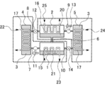
- FIG. 1 is a schematic diagram illustrating an example of an adsorption heat pump.
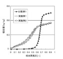
- 2 is a water vapor adsorption isotherm of the adsorbent for the adsorption heat pump of Example 1, Example 2, and Comparative Example 1.
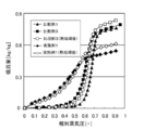
- FIG. 3 is a water vapor adsorption isotherm of the adsorption heat pump adsorbent of Example 3, Example 4, and Comparative Example 1.
- FIG. 4 is a water vapor adsorption isotherm of the adsorption heat pump adsorbent of Example 5, Example 6, and Comparative Example 2.
- FIG. 5 is a water vapor adsorption isotherm of the adsorption heat pump adsorbent of Example 1, Example 7, Example 8, and Comparative Example 1.
- FIG. 1 is a schematic diagram illustrating an example of an adsorption heat pump.
- 2 is a water vapor adsorption isotherm of the adsorbent for the adsorption heat pump of Example 1, Example 2, and Comparative Example 1.
- FIG. 6 is a water vapor adsorption isotherm of the adsorption heat pump adsorbent of Comparative Example 1 and Comparative Example 3.
- FIG. FIG. 7 is a water vapor adsorption isotherm of the adsorption heat pump adsorbent of Comparative Example 2 and Comparative Example 4.
- FIG. 8 is a water vapor adsorption isotherm of the adsorption heat pump adsorbent of Example 1, Example 1 after heat treatment, Comparative Example 1, Comparative Example 3, and Comparative Example 3 after heat treatment.
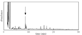
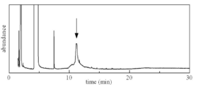
- FIG. 9 shows the results of gas chromatograph mass analysis (GC-MS analysis) of the adsorption heat pump adsorbent of Example 2.
- GC-MS analysis gas chromatograph mass analysis
- FIG. 10 shows the GC-MS analysis result of the adsorption heat pump adsorbent of Example 3.
- FIG. 11 shows the results of GC-MS analysis of the adsorption heat pump adsorbent of Example 4.
- 12 shows the GC-MS analysis results of the adsorption heat pump adsorbent of Example 5.
- the adsorbent for the adsorption heat pump disclosed herein includes activated carbon and organic molecules having at least one hydrophilic functional group in the pores of the activated carbon.
- hydrophilic treatment of activated carbon it is possible to increase the hydrophilicity in the pores by containing organic molecules having a hydrophilic functional group in the pores of the activated carbon. Moreover, the amount and type of the hydrophilic functional group can be strictly controlled by introducing the hydrophilic functional group into the pores in the form of molecules.
- the specific surface area of the activated carbon is not particularly limited and may be appropriately selected depending on the intended purpose. It is preferably 1,000 m 2 / g to 2,500 m 2 / g, and preferably 1,200 m 2 / g to 2, 000 m 2 / g is more preferable. When the specific surface area is within the more preferable range, a high performance adsorption heat pump adsorbent in which adsorption / desorption reaction proceeds in a relative vapor pressure range of 0.2 to 0.6 on the adsorption isotherm can be obtained. This is advantageous.
- the specific surface area can be determined, for example, by measuring a nitrogen adsorption isotherm using a specific surface area / pore distribution measuring apparatus (BELSORP-mini, Japan Bell Co., Ltd.) and analyzing by the BET method.
- the activated carbon may be a manufactured product or a commercially available product.
- Examples of the commercially available products include spherical activated carbon, Dazai Q type (Futamura Chemical Co., Ltd.), Kureha spherical activated carbon BAC (Kureha Co., Ltd.), and the like.
- Organic molecule has at least one hydrophilic functional group.
- the organic molecule is present in the pores of the activated carbon.
- the molecular weight of the organic molecule is not particularly limited and may be appropriately selected depending on the intended purpose, but is preferably 50 to 300, more preferably 60 to 280, and particularly preferably 90 to 270.
- the molecular weight of the organic molecule is less than 50, the organic molecule tends to come out from the pores of the activated carbon, and the hydrophilicity of the adsorbent for the adsorption heat pump may be reduced. The adsorptivity of the heat pump adsorbent may decrease.
- the adsorbent for the adsorption heat pump to be obtained has an appropriate hydrophilicity, and the adsorption isotherm absorbs in a relative vapor pressure range of 0.2 to 0.6. This is advantageous in that a high-performance adsorbent for an adsorption heat pump in which a desorption reaction proceeds can be obtained.
- the number of carbon atoms of the organic molecule excluding the number of carbon atoms of the hydrophilic functional group is not particularly limited and may be appropriately selected depending on the intended purpose, but is preferably 1 to 10, and more preferably 1 to 6. When the number of carbon atoms of the organic molecule excluding the number of carbon atoms of the hydrophilic functional group exceeds 10, the adsorptivity of the adsorption heat pump adsorbent may be lowered.
- the hydrophilicity of the adsorbent for the adsorption heat pump to be obtained becomes appropriate, and the relative vapor in the adsorption isotherm This is advantageous in that a high-performance adsorption heat pump adsorbent can be obtained in which the adsorption / desorption reaction proceeds in a pressure range of 0.2 to 0.6.
- the hydrophilic functional group is a functional group having polarity.
- the hydrophilic functional group is, for example, a functional group capable of hydrogen bonding with another functional group.
- Examples of the hydrophilic functional group include a hydroxyl group, a carbonyl group, a carboxyl group, and a sulfo group.
- the at least one hydrophilic functional group in the organic molecule is not particularly limited and may be appropriately selected depending on the intended purpose, but is at least one of a hydroxyl group, a carbonyl group, a carboxyl group, and a sulfo group. Is preferred.
- the hydrophilicity of the adsorbent for the adsorption heat pump obtained becomes moderate, and the adsorption / desorption reaction proceeds in the range of relative vapor pressure of 0.2 to 0.6 on the adsorption isotherm. An adsorbent for heat pump is obtained.
- the number of the hydrophilic functional groups in the organic molecule is not particularly limited and may be appropriately selected depending on the intended purpose, but is preferably 1 to 4. By doing so, the hydrophilicity of the adsorbent for the adsorption heat pump obtained becomes moderate, and the adsorption / desorption reaction proceeds in the range of relative vapor pressure of 0.2 to 0.6 on the adsorption isotherm. An adsorbent for heat pump is obtained.
- the organic molecule is at least one of maleic acid (molecular weight 116), methanesulfonic acid (molecular weight 96), squaric acid (molecular weight 114), sulfoisophthalic acid (molecular weight 246), and benzenetetracarboxylic acid (molecular weight 254). It is preferable.
- Examples of the sulfoisophthalic acid include 5-sulfoisophthalic acid.
- Examples of the benzenetetracarboxylic acid include pyromellitic acid.
- the maleic acid, the methanesulfonic acid, the squaric acid, the 5-sulfoisophthalic acid, and the pyromellitic acid are each represented by the following structural formula.
- the method for producing the adsorbent for adsorption heat pump is not particularly limited and may be appropriately selected depending on the intended purpose. However, the method for producing an adsorbent for adsorption heat pump described below is preferred.
- the disclosed method for producing an adsorbent for an adsorption heat pump includes at least a dipping step, preferably a heating step, and further includes other steps as necessary.
- the method for producing the adsorption heat pump adsorbent is a method for producing the adsorption heat pump adsorbent disclosed.
- the immersion step is not particularly limited as long as it is a step of immersing the activated carbon in a liquid containing the organic molecule, and can be appropriately selected according to the purpose.
- the amount of the activated carbon with respect to the liquid during the immersion is not particularly limited and can be appropriately selected depending on the purpose.
- the immersion time is not particularly limited and may be appropriately selected depending on the intended purpose. It is preferably 1 hour to 48 hours, more preferably 2 hours to 24 hours, and particularly preferably 6 hours to 18 hours.
- the temperature of the liquid during the immersion is not particularly limited and may be appropriately selected depending on the intended purpose, but is preferably 10 ° C. to 50 ° C., more preferably 20 ° C. to 40 ° C.
- the organic solvent solution containing the said organic molecule may be sufficient, and the aqueous solution containing the said organic molecule may be sufficient.
- the organic molecule is a liquid, it may be the organic molecule itself.
- the aqueous solution containing the organic molecule is preferable in terms of easy handling.
- the content of the organic molecules in the liquid is not particularly limited and can be appropriately selected according to the purpose, but it is easy to adjust the amount of the organic molecules introduced into the pores of the activated carbon. 0.1 mass% to 10 mass% is preferable, 0.5 mass% to 5 mass% is more preferable, and 1 mass% to 4 mass% is particularly preferable.
- Examples of the organic solvent in the organic solvent solution include alcohol and toluene.
- Examples of the alcohol include methanol and ethanol.
- the heating step is not particularly limited as long as it is a step for heating the activated carbon after the immersion and obtaining the activated carbon having the organic molecules in the pores, and is appropriately selected according to the purpose. Can do.
- the heating temperature of the activated carbon is not particularly limited and may be appropriately selected depending on the intended purpose, but is preferably from 100 ° C. to 250 ° C. from the viewpoint of efficiently removing unnecessary organic molecules.
- the heating time is not particularly limited and may be appropriately selected depending on the intended purpose. It is preferably 0.5 to 6 hours, and more preferably 1 to 3 hours.
- the heating of the activated carbon is preferably performed under reduced pressure from the viewpoint that the unnecessary organic molecules can be efficiently removed.
- the disclosed adsorption heat pump has at least the disclosed adsorption heat pump adsorbent, and further includes other means as necessary.
- the disclosed adsorption heat pump includes an evaporator 1 that evaporates liquid adsorbate to form a gas adsorbate, and a condenser 2 that condenses gas adsorbate to form a liquid adsorbate. And two adsorbers 4 and 5 each having an adsorbent 3 for adsorption heat pump that can adsorb and desorb adsorbate.
- the evaporator 1 and the condenser 2 are connected by a first flow path 6.
- One adsorber 4 is connected to one side (left side in FIG. 1) of the evaporator 1 and the condenser 2.
- one side of the evaporator 1 and the one adsorber 4 are connected by the second flow path 7, and one side of the condenser 2 and the one adsorber 4 are connected to the third flow path 8.
- another adsorber 5 is connected to the other side (right side in FIG. 1) of the evaporator 1 and the condenser 2. That is, the other side of the condenser 2 and the other adsorber 5 are connected by the fourth flow path 9, and the other side of the evaporator 1 and the other adsorber 5 are connected to the fifth flow path 10.
- the second flow path 7, the third flow path 8, the fourth flow path 9, and the fifth flow path 10 are provided with valves 11 to 14 for opening and closing the flow paths, respectively.
- the evaporator 1, the condenser 2, the adsorbers 4, 5 and the flow paths 6 to 10 each have a space sealed inside, and when using the adsorption heat pump, this space is normally decompressed. It has become.
- the evaporator 1 changes the phase of the liquid adsorbate 21 to a gas adsorbate, includes a heat exchanger for taking out the cold heat 23, and the liquid adsorbate 21 is used as a heat transfer medium.
- a tubular member 15 is provided for flowing a fluid capable of transporting cold heat 23 generated during evaporation to the outside.
- gas adsorbate is adsorbed by one of the adsorbers (adsorber 4 in FIG. 1) during the adsorption process, and from the evaporator 1 via the flow path (second flow path 7 in FIG. 1).
- the liquid adsorbate 21 evaporates.
- the cold heat 23 generated when the liquid adsorbate 21 evaporates is transported to the outside by a fluid as a heat transport medium flowing inside the tubular member 15 and is used for cooling, for example.
- the condenser 2 is a heat exchanger that cools the gaseous adsorbate and changes the phase to the liquid adsorbate 20.
- the condenser 2 is a fluid having a temperature lower than the condensation point of the adsorbate (here, cooling water).
- a tubular member 16 is provided. The condenser 2 cools the adsorbate of gas flowing in from the one adsorber (adsorber 5 in FIG. 1) through the flow path (fourth flow path 9 in FIG. 1) during the desorption process, and adsorbs the liquid. Phase change to quality 20. Then, the liquid adsorbate 20 is sent from the condenser 2 to the evaporator 1 via the first flow path 6.
- the adsorbate is, for example, water. An alcohol such as methanol or ethanol may be used as the adsorbate.
- the adsorbers 4 and 5 are heat exchangers each including a tubular member 17 through which a fluid can flow.
- the adsorbent 3 for the adsorption heat pump is filled around the tubular member 17.
- desorption of the adsorbate occurs predominantly at a specific temperature or higher, and adsorption occurs predominantly at a lower temperature.
- the temperature of the adsorbent heat pump adsorbent 3 is controlled by the temperature of the fluid flowing through the tubular member 17, whereby the desorption or adsorption of the adsorbate is controlled. That is, in the adsorption process of adsorbing the adsorbate to the adsorbent heat pump adsorbent 3 provided in the adsorbers 4 and 5, the tubular member 17 is used as a heat transfer medium that can be controlled to a temperature at which adsorption of the adsorbate is dominant. Of fluid.
- the adsorbate is adsorbed by the adsorbent heat pump adsorbent 3 by flowing the cooling water 22 as a heat transfer medium and cooling the adsorbent heat pump adsorbent 3.
- the adsorbate is desorbed from the adsorbent 3 for the adsorption heat pump provided in the adsorbers 4 and 5, as a heat transfer medium that can be controlled to a temperature at which the desorption of the adsorbate is dominant on the tubular member 17.
- Flow fluid the temperature required to desorb the adsorbate from the adsorption heat pump adsorbent 3 is about 60 ° C. For this reason, a relatively low-temperature waste heat of about 100 ° C. or less is used as the heat.
- the adsorbate is desorbed from the adsorption heat pump adsorbent 3 by conveying the heat recovered from waste heat or the like by a fluid as a heat transfer medium and heating the adsorbent heat pump adsorbent 3.
- the adsorption process and the desorption process can be repeated to continuously generate cold from the heat.
- FIG. 1 when the valves 11 and 13 are opened and the valves 12 and 14 are closed, one adsorber 4 (left side in FIG. 1) is connected to the evaporator 1.
- the other adsorber 5 (right side in FIG. 1) is connected to the condenser 2.
- cooling water 22 is allowed to flow through one of the adsorbers 4 to cool the adsorbent heat pump adsorbent 3, and the other adsorber 5 conveys warm heat 24 recovered from waste heat or the like by a fluid.
- the adsorbent 3 for the adsorption heat pump is heated.
- the adsorbate is adsorbed on the adsorbent heat pump adsorbent 3 provided in one adsorber 4, and the adsorbate is desorbed from the adsorbent heat pump adsorbent 3 provided in the other adsorber 5. That is, one adsorber 4 connected to the evaporator 1 becomes an adsorption process, and the other adsorber 5 connected to the condenser 2 becomes a desorption process.
- the other adsorber 5 (right side in FIG. 1) is connected to the evaporator 1 and one adsorber 4 (left side in FIG. 1) is connected to the condenser 2.
- cooling water is allowed to flow through the other adsorber 5 to cool the adsorbent heat pump adsorbent 3, and the heat recovered from the waste heat or the like is conveyed to the one adsorber 4 by the fluid,
- the adsorbent 3 for the adsorption heat pump is heated.
- the adsorbate is adsorbed by the adsorbent heat pump adsorbent 3 provided in the other adsorber 5, and the adsorbate is desorbed from the adsorbent heat pump adsorbent 3 provided in the one adsorber 4. That is, the other adsorber 5 connected to the evaporator 1 becomes an adsorption process, and the one adsorber 4 connected to the condenser 2 becomes a desorption process.
- the adsorption process and the desorption process can be repeated, and cold heat can be continuously generated from the hot heat.
- the adsorption process of one adsorber 4 and the desorption process of the other adsorber 5 are performed simultaneously, and the desorption process of one adsorber 4 and the adsorption process of the other adsorber 5 are performed simultaneously.
- the present invention is not limited to this.
- the adsorption process of one adsorber 4 and the adsorption process of the other adsorber 5 are performed simultaneously, and the desorption process of one adsorber 4 and the desorption process of the other adsorber 5 are performed simultaneously. It may be repeated.
- the adsorption process and the desorption process may be performed in stages.
- the valves 11 and 14 are opened, the valves 12 and 13 are closed, cooling water is supplied to both the adsorbers 4 and 5, and the adsorption heat pump adsorbent 3 is cooled. do it.
- the valves 12 and 13 are opened, the valves 11 and 14 are closed, and the heat recovered from the waste heat or the like is conveyed to both adsorbers 4 and 5 by a fluid. What is necessary is just to heat the adsorbent 3 for heat pumps.
- the disclosed adsorption heat pump adsorbent and the production method thereof will be described in more detail with reference to examples.
- the disclosed adsorption heat pump adsorbent and the production method thereof are not limited to these examples. It is not something.
- the specific surface area and water vapor adsorption isotherm were measured by the following methods.
- ⁇ Specific surface area> The nitrogen adsorption isotherm was measured using a specific surface area / pore distribution measuring device (BELSORP-mini, Japan Bell Co., Ltd.), and the specific surface area was determined by analysis by the BET method.
- the measurement sample was pretreated by vacuum heating at 150 ° C. for 3 hours.
- Water vapor adsorption isotherm> The water vapor adsorption isotherm was measured using an adsorption isotherm measuring device (Belsorb-aqua3, manufactured by Nippon Bell Co., Ltd.). Obtained by condition. The measurement sample was pretreated by vacuum heating at 150 ° C. for 3 hours.
- Comparative Example 1 As an adsorbent for the adsorption heat pump of Comparative Example 1, activated carbon (spherical activated carbon Dazai Q type, manufactured by Phutamura Chemical Co., Ltd., specific surface area: 2,000 m 2 / g) was used.
- Example 1 After immersing 0.5 g of activated carbon (spherical activated carbon Dazai Q type, manufactured by Futamura Chemical Co., Ltd., specific surface area: 2,000 m 2 / g) in 25 mL of a 2 mass% aqueous solution of 5-sulfoisophthalic acid for 12 hours, And then vacuum-dried at 150 ° C. for 2 hours to obtain an adsorbent for an adsorption heat pump.
- activated carbon spherical activated carbon Dazai Q type, manufactured by Futamura Chemical Co., Ltd., specific surface area: 2,000 m 2 / g
- Example 2 In Example 1, the same procedure as in Example 1 was performed except that the 2% by mass aqueous solution of 5-sulfoisophthalic acid was changed to a 2% by mass aqueous solution of 1,2,4,5-benzenetetracarboxylic acid (pyromellitic acid). Thus, an adsorbent for adsorption heat pump was obtained.
- Example 3 An adsorbent for an adsorption heat pump was obtained in the same manner as in Example 1 except that the 2% by mass aqueous solution of 5-sulfoisophthalic acid in Example 1 was changed to a 2% by mass aqueous solution of maleic acid.
- Example 4 An adsorption heat pump adsorbent was obtained in the same manner as in Example 1 except that the 2 mass% aqueous solution of 5-sulfoisophthalic acid in Example 1 was changed to a 1 mass% aqueous solution of squaric acid.
- Comparative Example 2 As the adsorbent for the adsorption heat pump of Comparative Example 2, activated carbon (Kureha Spherical Activated Carbon BAC, manufactured by Kureha Corporation, specific surface area: 1,200 m 2 / g) was used.
- Kureha Spherical Activated Carbon BAC manufactured by Kureha Corporation, specific surface area: 1,200 m 2 / g
- Example 5 After immersing 0.5 g of activated carbon (Kureha spherical activated carbon BAC, manufactured by Kureha Co., Ltd., specific surface area: 1,200 m 2 / g) in 25 mL of a 2% by weight aqueous solution of maleic acid for 12 hours, this was washed with water, An adsorbent for adsorption heat pump was obtained by vacuum drying at 150 ° C. for 2 hours.
- activated carbon Karl spherical activated carbon BAC, manufactured by Kureha Co., Ltd., specific surface area: 1,200 m 2 / g
- Example 6 an adsorbent for adsorption heat pump was obtained in the same manner as in Example 5 except that the 2% by mass aqueous solution of maleic acid was changed to a 2% by mass aqueous solution of methanesulfonic acid.
- Example 7 an adsorbent for an adsorption heat pump was obtained in the same manner as in Example 1 except that the 2% by mass aqueous solution of 5-sulfoisophthalic acid was changed to a 0.4% by mass aqueous solution of 5-sulfoisophthalic acid. It was.
- Example 8 An adsorption heat pump adsorbent was obtained in the same manner as in Example 1 except that the 2 mass% aqueous solution of 5-sulfoisophthalic acid in Example 1 was changed to a 4 mass% aqueous solution of 5-sulfoisophthalic acid.
- Comparative Example 4 In Comparative Example 3, the adsorbent for the adsorption heat pump was changed in the same manner as in Comparative Example 3 except that the activated carbon was changed to activated carbon (Kureha spherical activated carbon BAC, manufactured by Kureha Co., Ltd., specific surface area: 1,200 m 2 / g). Obtained.
- FIG. 9 is a GC-MS result of the adsorption heat pump adsorbent of Example 2.
- FIG. 10 shows GC-MS results of the adsorption heat pump adsorbent of Example 3.
- FIG. 11 shows the GC-MS results of the adsorption heat pump adsorbent of Example 4.
- 12 shows the GC-MS result of the adsorbent for the adsorption heat pump of Example 5.
- FIG. 9 to 12 a peak derived from an organic molecule was confirmed at a position indicated by an arrow in the figure.
Landscapes
- Chemical & Material Sciences (AREA)
- Organic Chemistry (AREA)
- Analytical Chemistry (AREA)
- Chemical Kinetics & Catalysis (AREA)
- Inorganic Chemistry (AREA)
- Physics & Mathematics (AREA)
- Engineering & Computer Science (AREA)
- Thermal Sciences (AREA)
- Mechanical Engineering (AREA)
- General Engineering & Computer Science (AREA)
- Sorption Type Refrigeration Machines (AREA)
- Solid-Sorbent Or Filter-Aiding Compositions (AREA)
Abstract
Priority Applications (4)
| Application Number | Priority Date | Filing Date | Title |
|---|---|---|---|
| JP2015517970A JP6119849B2 (ja) | 2013-05-22 | 2013-05-22 | 吸着式ヒートポンプ用吸着剤、及びその製造方法、並びに吸着式ヒートポンプ |
| CN201380076751.5A CN105228740B (zh) | 2013-05-22 | 2013-05-22 | 吸附式热泵用吸附剂及其制造方法、以及吸附式热泵 |
| PCT/JP2013/064142 WO2014188523A1 (fr) | 2013-05-22 | 2013-05-22 | Adsorbant pour pompe à chaleur à adsorption, procédé de fabrication correspondant, et pompe à chaleur à adsorption |
| US14/926,543 US9975108B2 (en) | 2013-05-22 | 2015-10-29 | Adsorbent for adsorption heat pumps, production method thereof, and adsorption heat pump |
Applications Claiming Priority (1)
| Application Number | Priority Date | Filing Date | Title |
|---|---|---|---|
| PCT/JP2013/064142 WO2014188523A1 (fr) | 2013-05-22 | 2013-05-22 | Adsorbant pour pompe à chaleur à adsorption, procédé de fabrication correspondant, et pompe à chaleur à adsorption |
Related Child Applications (1)
| Application Number | Title | Priority Date | Filing Date |
|---|---|---|---|
| US14/926,543 Continuation US9975108B2 (en) | 2013-05-22 | 2015-10-29 | Adsorbent for adsorption heat pumps, production method thereof, and adsorption heat pump |
Publications (1)
| Publication Number | Publication Date |
|---|---|
| WO2014188523A1 true WO2014188523A1 (fr) | 2014-11-27 |
Family
ID=51933113
Family Applications (1)
| Application Number | Title | Priority Date | Filing Date |
|---|---|---|---|
| PCT/JP2013/064142 Ceased WO2014188523A1 (fr) | 2013-05-22 | 2013-05-22 | Adsorbant pour pompe à chaleur à adsorption, procédé de fabrication correspondant, et pompe à chaleur à adsorption |
Country Status (4)
| Country | Link |
|---|---|
| US (1) | US9975108B2 (fr) |
| JP (1) | JP6119849B2 (fr) |
| CN (1) | CN105228740B (fr) |
| WO (1) | WO2014188523A1 (fr) |
Families Citing this family (1)
| Publication number | Priority date | Publication date | Assignee | Title |
|---|---|---|---|---|
| KR102044876B1 (ko) * | 2017-11-22 | 2019-11-14 | 한국에너지기술연구원 | 실내 습도 조절이 가능한 수분 흡/탈착재 및 이의 제조방법 |
Citations (7)
| Publication number | Priority date | Publication date | Assignee | Title |
|---|---|---|---|---|
| JPH04346814A (ja) * | 1991-05-23 | 1992-12-02 | Toyobo Co Ltd | 吸湿材料 |
| JPH0674596A (ja) * | 1992-06-25 | 1994-03-15 | Mitsubishi Heavy Ind Ltd | 吸着式冷却装置 |
| JPH09239267A (ja) * | 1996-03-08 | 1997-09-16 | Osaka Gas Co Ltd | 活性炭素繊維紙への添着剤添着方法 |
| JPH10263394A (ja) * | 1997-03-28 | 1998-10-06 | Kubota Corp | 改良吸着剤、及び、その製造方法、及び、吸着冷凍機 |
| JP2002255531A (ja) * | 2000-12-26 | 2002-09-11 | Mitsubishi Chemicals Corp | 炭素質多孔材および廃熱利用装置 |
| JP2004223385A (ja) * | 2003-01-22 | 2004-08-12 | R Tec:Kk | 調湿材料 |
| JP2005289690A (ja) * | 2004-03-31 | 2005-10-20 | Univ Nagoya | シリカゲル添着活性炭、及びこれを用いた吸着ヒートポンプ |
Family Cites Families (13)
| Publication number | Priority date | Publication date | Assignee | Title |
|---|---|---|---|---|
| JPS5247355B2 (fr) * | 1974-10-15 | 1977-12-01 | ||
| JPS5498095A (en) * | 1978-01-18 | 1979-08-02 | Kuraray Co | Adsorptive blood purifier |
| US5063196A (en) * | 1989-06-23 | 1991-11-05 | Calgon Carbon Corporation | Chromium-free impregnated activated carbon for adsorption of toxic gases and/or vapors |
| US5658372A (en) * | 1995-07-10 | 1997-08-19 | Corning Incorporated | System and method for adsorbing contaminants and regenerating the adsorber |
| JPH1163721A (ja) | 1997-08-08 | 1999-03-05 | Yazaki Corp | 冷媒・吸着剤及びこれを用いた吸着式冷熱発生装置 |
| KR100744984B1 (ko) * | 1999-11-16 | 2007-08-02 | 혼다 기켄 고교 가부시키가이샤 | 전기 이중층 캐패시터용 전극 및 그것의 제조 방법 |
| JP3597783B2 (ja) | 2001-02-09 | 2004-12-08 | 昌信 架谷 | 吸着ヒートポンプ用活性炭の製造方法 |
| WO2002066910A1 (fr) * | 2001-02-21 | 2002-08-29 | Mitsubishi Chemical Corporation | Pompe a chaleur d'adsorption et utilisation d'un materiau d'adsorption pour ladite pompe |
| CN1626455A (zh) * | 2003-12-09 | 2005-06-15 | 煤炭科学研究总院北京煤化工研究分院 | 一种控制净化水pH值升高的活性炭及其制备方法 |
| JP2005288224A (ja) | 2004-03-31 | 2005-10-20 | Univ Nagoya | 親水性活性炭、及びこれを用いた吸着ヒートポンプ |
| US20110315922A1 (en) | 2008-11-04 | 2011-12-29 | Donaldson Company Inc. | Custom water adsorption material |
| US8496734B2 (en) * | 2009-02-26 | 2013-07-30 | Corning Incorporated | Sorbent structure applicable for carbon dioxide capture |
| WO2013030946A1 (fr) * | 2011-08-30 | 2013-03-07 | 富士通株式会社 | Adsorbant et son procédé de production |
-
2013
- 2013-05-22 JP JP2015517970A patent/JP6119849B2/ja not_active Expired - Fee Related
- 2013-05-22 WO PCT/JP2013/064142 patent/WO2014188523A1/fr not_active Ceased
- 2013-05-22 CN CN201380076751.5A patent/CN105228740B/zh not_active Expired - Fee Related
-
2015
- 2015-10-29 US US14/926,543 patent/US9975108B2/en active Active
Patent Citations (7)
| Publication number | Priority date | Publication date | Assignee | Title |
|---|---|---|---|---|
| JPH04346814A (ja) * | 1991-05-23 | 1992-12-02 | Toyobo Co Ltd | 吸湿材料 |
| JPH0674596A (ja) * | 1992-06-25 | 1994-03-15 | Mitsubishi Heavy Ind Ltd | 吸着式冷却装置 |
| JPH09239267A (ja) * | 1996-03-08 | 1997-09-16 | Osaka Gas Co Ltd | 活性炭素繊維紙への添着剤添着方法 |
| JPH10263394A (ja) * | 1997-03-28 | 1998-10-06 | Kubota Corp | 改良吸着剤、及び、その製造方法、及び、吸着冷凍機 |
| JP2002255531A (ja) * | 2000-12-26 | 2002-09-11 | Mitsubishi Chemicals Corp | 炭素質多孔材および廃熱利用装置 |
| JP2004223385A (ja) * | 2003-01-22 | 2004-08-12 | R Tec:Kk | 調湿材料 |
| JP2005289690A (ja) * | 2004-03-31 | 2005-10-20 | Univ Nagoya | シリカゲル添着活性炭、及びこれを用いた吸着ヒートポンプ |
Also Published As
| Publication number | Publication date |
|---|---|
| US20160045892A1 (en) | 2016-02-18 |
| JP6119849B2 (ja) | 2017-04-26 |
| CN105228740B (zh) | 2017-12-05 |
| US9975108B2 (en) | 2018-05-22 |
| JPWO2014188523A1 (ja) | 2017-02-23 |
| CN105228740A (zh) | 2016-01-06 |
Similar Documents
| Publication | Publication Date | Title |
|---|---|---|
| Tso et al. | Activated carbon, silica-gel and calcium chloride composite adsorbents for energy efficient solar adsorption cooling and dehumidification systems | |
| Kong et al. | Development of monolithic adsorbent via polymeric sol–gel process for low-concentration CO2 capture | |
| JP5298292B2 (ja) | 吸着剤を利用した水分除去、冷熱の回収を行う、温度スイング法voc濃縮、低温液化voc回収方法。 | |
| US6960243B1 (en) | Production of drinking water from air | |
| US8365575B2 (en) | Chemically modified organic CDC based rapid analysis system | |
| CN105797690A (zh) | 一种提高对含水有机气体吸附的疏水性涂层活性炭制备和再生方法 | |
| Fujiki et al. | Water adsorption on nitrogen-doped carbons for adsorption heat pump/desiccant cooling: Experimental and density functional theory calculation studies | |
| JP6119849B2 (ja) | 吸着式ヒートポンプ用吸着剤、及びその製造方法、並びに吸着式ヒートポンプ | |
| CN102068960B (zh) | 吸附氮氧化物蜂窝活性炭吸附剂的再生方法 | |
| US20160045893A1 (en) | Adsorbent, method of manufacturing adsorbent, and adsorption-type heat pump | |
| JP6221718B2 (ja) | 吸着式ヒートポンプ用吸着剤、及びその製造方法、並びに吸着式ヒートポンプ | |
| US12285719B2 (en) | Solar-driven membrane-based open-cycle adsorption air conditioner | |
| JP6458465B2 (ja) | 有機溶剤回収システム | |
| WO2013030946A1 (fr) | Adsorbant et son procédé de production | |
| CN105333640B (zh) | 一种带有刺孔膜片式吸附质管的壳管式吸附床 | |
| Trisupakitti et al. | Adsorption Cooling System Using Metal‐Impregnated Zeolite‐4A | |
| Gethard et al. | Carbon nanotube enhanced membrane distillation for online preconcentration of trace pharmaceuticals in polar solvents | |
| JP6314740B2 (ja) | 吸着式ヒートポンプ用吸着剤の製造方法 | |
| TWI537037B (zh) | 水回收系統及應用其進行水回收的方法 | |
| CN205351849U (zh) | 一种带有刺孔膜片式吸附质管的壳管式吸附床 | |
| JP2013202552A (ja) | 吸着式ヒートポンプ用吸着剤、及びその製造方法 | |
| JP2008100187A (ja) | 有機溶剤含有ガス処理システム | |
| JP2012081443A (ja) | 溶剤脱水装置 | |
| JP2012005922A (ja) | 有機溶剤回収システム | |
| JP2011240256A (ja) | 吸着剤ブロック及びその製造方法、吸着器、吸着式ヒートポンプ |
Legal Events
| Date | Code | Title | Description |
|---|---|---|---|
| WWE | Wipo information: entry into national phase |
Ref document number: 201380076751.5 Country of ref document: CN |
|
| 121 | Ep: the epo has been informed by wipo that ep was designated in this application |
Ref document number: 13885011 Country of ref document: EP Kind code of ref document: A1 |
|
| ENP | Entry into the national phase |
Ref document number: 2015517970 Country of ref document: JP Kind code of ref document: A |
|
| NENP | Non-entry into the national phase |
Ref country code: DE |
|
| 122 | Ep: pct application non-entry in european phase |
Ref document number: 13885011 Country of ref document: EP Kind code of ref document: A1 |