WO2014192525A1 - データ処理装置およびデータ処理方法 - Google Patents
データ処理装置およびデータ処理方法 Download PDFInfo
- Publication number
- WO2014192525A1 WO2014192525A1 PCT/JP2014/062647 JP2014062647W WO2014192525A1 WO 2014192525 A1 WO2014192525 A1 WO 2014192525A1 JP 2014062647 W JP2014062647 W JP 2014062647W WO 2014192525 A1 WO2014192525 A1 WO 2014192525A1
- Authority
- WO
- WIPO (PCT)
- Prior art keywords
- data
- template
- pattern
- similarity
- comparison
- Prior art date
- Legal status (The legal status is an assumption and is not a legal conclusion. Google has not performed a legal analysis and makes no representation as to the accuracy of the status listed.)
- Ceased
Links
Images





Classifications
-
- B—PERFORMING OPERATIONS; TRANSPORTING
- B25—HAND TOOLS; PORTABLE POWER-DRIVEN TOOLS; MANIPULATORS
- B25J—MANIPULATORS; CHAMBERS PROVIDED WITH MANIPULATION DEVICES
- B25J9/00—Program-controlled manipulators
- B25J9/16—Program controls
- B25J9/1674—Program controls characterised by safety, monitoring, diagnostic
-
- G—PHYSICS
- G05—CONTROLLING; REGULATING
- G05B—CONTROL OR REGULATING SYSTEMS IN GENERAL; FUNCTIONAL ELEMENTS OF SUCH SYSTEMS; MONITORING OR TESTING ARRANGEMENTS FOR SUCH SYSTEMS OR ELEMENTS
- G05B23/00—Testing or monitoring of control systems or parts thereof
- G05B23/02—Electric testing or monitoring
- G05B23/0205—Electric testing or monitoring by means of a monitoring system capable of detecting and responding to faults
- G05B23/0218—Electric testing or monitoring by means of a monitoring system capable of detecting and responding to faults characterised by the fault detection method dealing with either existing or incipient faults
- G05B23/0221—Preprocessing measurements, e.g. data collection rate adjustment; Standardization of measurements; Time series or signal analysis, e.g. frequency analysis or wavelets; Trustworthiness of measurements; Indexes therefor; Measurements using easily measured parameters to estimate parameters difficult to measure; Virtual sensor creation; De-noising; Sensor fusion; Unconventional preprocessing inherently present in specific fault detection methods like PCA-based methods
-
- G—PHYSICS
- G05—CONTROLLING; REGULATING
- G05B—CONTROL OR REGULATING SYSTEMS IN GENERAL; FUNCTIONAL ELEMENTS OF SUCH SYSTEMS; MONITORING OR TESTING ARRANGEMENTS FOR SUCH SYSTEMS OR ELEMENTS
- G05B2219/00—Program-control systems
- G05B2219/30—Nc systems
- G05B2219/37—Measurements
- G05B2219/37508—Cross correlation
Definitions
- the present invention relates to a data processing apparatus and a data processing method for processing a large amount of data generated in time series.
- a data processing method for processing a large amount of data generated in time series is used, for example, as a failure diagnosis method for industrial robots (see Patent Document 1).
- a failure diagnosis method for an industrial robot collects and extracts data from an industrial robot that uses a servo motor as a drive source, performs predetermined processing, and uses that data to monitor changes over time in the industrial robot. ing.
- the system is configured such that a predetermined operation is periodically executed, data at that time is acquired, and an alarm is issued if there is an abnormality compared with the reference data at the beginning of introduction.
- the reference data collecting operation is prepared and executed separately from the normal production operation. For this reason, since the operation conditions such as speed and the operation pattern are different from those of normal production operation, the analysis that is regarded as secular change is not accurate. In other words, it is difficult to accurately and easily extract from the large amount of data generated in time series the same comparison data as the operation pattern data based on the operating conditions, environmental conditions, operation patterns, and other prerequisites. Met.
- An object of the present invention is to provide a data processing apparatus and a data processing method capable of easily and accurately extracting data to be compared from a large amount of data generated in time series.
- a first aspect of the present invention is a data processing apparatus that collects and processes a large amount of data generated in time series, the storage unit storing the input data, and the storage unit stored in the storage unit A pattern extraction unit that extracts a template of a reference operation pattern from the data and a comparison pattern similar to the template, and the pattern extraction unit creates the template from the data
- a template creation unit a comparison pattern selected from the data, a similarity acquisition unit that acquires similarity with the template, and the template based on the similarity acquired by the similarity acquisition unit
- a comparison pattern extraction unit that extracts and stores a comparison pattern that is a similar operation pattern.
- this data processing apparatus it is possible to easily and accurately extract data to be compared from a large amount of data generated in time series.
- the present invention may be configured such that the similarity determination unit of the pattern extraction unit determines the similarity based on a correlation value between the template and the comparison pattern.
- the similarity is obtained using the correlation value, the expression is not a high-order and complicated expression. Therefore, the processing time may be short, and the computer may not be a high-performance computer. Excellent in properties.
- the data generated in time series includes command data input to control the operation of the industrial robot, and servo data output from the industrial robot operated based on the command data.
- the template and the comparison pattern may be created from the command data, and the pattern extraction unit may compare the corresponding data of the template and the comparison pattern.
- the servo data includes torque data, and the pattern extraction unit compares the torque data corresponding to the template and the comparison pattern.
- the servo is premised on the same input condition (template and operation pattern). There are advantages to comparing the data.
- a data processing method for collecting and processing a large amount of data generated in a sequence, a storage step for storing the input data in a storage unit, and an accumulation in the storage unit.
- a pattern extraction step for extracting a template of a reference operation pattern from the data and a comparison pattern similar to the template, and the pattern extraction step includes extracting the template from the data.
- a template creation step for creating a comparison pattern, a comparison pattern selected from the data, a similarity acquisition step for acquiring a similarity with the template, and a similarity acquired by the similarity acquisition step,
- a comparison pattern extraction step for extracting and storing a comparison pattern that is a similar operation pattern to the template. And, including the.
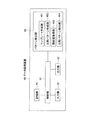
- FIG. 1 It is a figure showing an outline of a robot information processing system concerning an embodiment of the present invention. It is a block diagram which shows the structural example of the data processor which concerns on this embodiment. It is a figure which shows an example of accumulation
- FIG. 1 is a block diagram showing an outline of a robot information processing system according to an embodiment of the present invention.
- the robot information processing system 10 includes a robot body 20, a controller 30 that controls the operation of the robot body 20, and a data processing device 40, as shown in FIG.
- the robot body 20 and the controller 30 are configured as an industrial robot 50 that transports, for example, a semiconductor wafer or a glass substrate for a liquid crystal display panel (hereinafter referred to as a semiconductor wafer).
- the controller 30 controls the operation of the robot body 20, and the command data (position and speed) as input data in the normal production of the robot body 20 and servo data (torque, deviation, etc.) as output data are data processing devices. 40 is output in time series. That is, the command data and servo data are a large amount of data generated in time series.
- command data (position and speed) as input data is data created by a program or the like, and is not affected by aging.
- servo data (torque, deviation, etc.) as output data is data that is susceptible to secular changes such as a mechanical part that is a mechanical part constituting an industrial robot.
- the controller 30 of this embodiment uses a servo motor as a drive source of the robot arm 20ARM of the industrial robot 50, outputs command data from the controller 30 to the servo motor, and is attached to the servo motor.
- the detected value as servo data output from the encoder is fed back, and the rotational position of the servo motor and the like are made to coincide with the target value (command data) to follow the change of the target value (command data).
- the robot body 20 includes a robot base 21, an arm base portion 22, a first arm portion 23, a second arm portion 24, and a hand 25, for example.
- an arm base shaft portion 22 extending in the Z-axis direction (vertical direction in the figure) of the orthogonal coordinate system set in the figure is arranged on the robot base 21 so as to be movable up and down.
- the hand 25 is configured such that a transport object such as a semiconductor wafer is placed thereon.
- the hand 25 is formed so as to releasably hold a conveyance object such as a semiconductor wafer placed thereon.
- the second arm portion 24 is fixedly attached to a second arm rotation shaft 26 rotatably provided at the distal end portion of the first arm portion 23 at the base end portion.
- the hand 25 is fixedly attached to a hand shaft 27 rotatably disposed at the distal end portion of the second arm portion 24 at the base end portion.
- the robot arm 20ARM of the robot body 20 includes the arm base shaft portion 22, the first arm portion 23, the second arm portion 24, the hand 25, the second arm rotating shaft 26, and the hand shaft 27.
- This type of robot arm 20ARM is called a SCARA horizontal articulated arm.
- a controller 30 as a robot controller, the hand 25 is moved to the X, Y, and Z axes. It is possible to move to a desired position in the direction.
- the robot body 20 includes a first arm driving unit 201 that rotationally drives the first arm unit 23, a second arm driving unit 202 that rotationally drives the second arm unit 24, a hand axis driving unit 203 that rotationally drives the hand shaft 27, Also, there is an elevating drive unit 204 that elevates and lowers the arm base shaft part 22 in the Z-axis direction.
- the first arm drive unit 201 is disposed in the internal space of the robot base 21 and includes a servo motor incorporating an encoder and a power transmission mechanism thereof.
- the second arm drive unit 202 is disposed in the internal space of the first arm unit 23 and includes a servo motor incorporating an encoder and a power transmission mechanism thereof.
- the hand shaft drive unit 203 is disposed in the internal space of the second arm unit 24 and includes a servo motor incorporating an encoder and a power transmission mechanism thereof.
- the power transmission mechanism includes, for example, a speed reducer, the power of the servo motor is transmitted to the input side of the speed reducer, the torque is amplified by a predetermined amplification ratio, and the rotational speed is decelerated by a predetermined speed reduction ratio, Output from the output side of the reducer.
- a speed reducer the power of the servo motor is transmitted to the input side of the speed reducer, the torque is amplified by a predetermined amplification ratio, and the rotational speed is decelerated by a predetermined speed reduction ratio, Output from the output side of the reducer.
- each of the arm base shaft portion 22, the second arm rotation shaft 26, and the hand shaft 27 is rotationally driven by the power output from the output side of the reduction gear.
- each of the 1st arm part 23, the 2nd arm part 24, and the hand 25 is rotationally driven.
- the elevating drive unit 204 is disposed inside the robot base 21 and is realized by a ball screw mechanism using a motor capable of adjusting the amount of angular displacement.
- the lift drive unit 204 includes a ball screw, a screwed body that is screwed to the ball screw, and a motor that rotationally drives the ball screw, and the arm base shaft part 22 is fixed to the screwed body.
- a servo motor incorporating an encoder is used as the motor of the lift drive unit 204.
- the arm base shaft portion 22 is rotationally driven around the rotation axis RX1 with respect to the robot base 21 by the first arm driving portion 201.
- the first arm unit 23 is rotationally driven around the rotation axis RX ⁇ b> 1 with respect to the robot base 21.
- the second arm rotation shaft 26 is rotationally driven around the rotation axis RX2 with respect to the first arm portion 23 by the second arm driving unit 202. Accordingly, the second arm portion 24 is rotationally driven around the rotation axis RX ⁇ b> 2 with respect to the first arm portion 23.
- the hand shaft 27 is rotationally driven around the rotation axis RX3 with respect to the second arm unit 24 by the hand shaft driving unit 203.
- the hand 25 is rotationally driven around the rotation axis RX3 with respect to the second arm portion 24.
- the servo motors of the first arm driving unit 201, the second arm driving unit 202, the hand axis driving unit 203, and the lifting / lowering driving unit 204 are basically input by the controller 30 in normal production operations. And servo data such as torque and deviation is output to the controller 30 in time series.
- the controller 30 outputs a position or speed command to the first arm driving unit 201, the second arm driving unit 202, the hand axis driving unit 203, and the lifting / lowering driving unit 204 to be controlled, and the servo motor of each driving unit is output.
- Each drive unit is feedback-controlled by obtaining the angular position of each servo motor from the encoder. Thereby, the hand 25 can be accurately aligned with the target position.
- the controller 30 is generated in time series of commands (position or speed) and servo data (torque, deviation, etc.) that are information related to drive control of the servo system drive source (servo motor) of the robot body 20 in normal production operation.
- a large amount of data S30 is output to the data processing device 40.
- the position data (or velocity data) as the command data is input data that is input to control the operation of the industrial robot 50, and is data that is output from the controller 30 to the corresponding drive unit of the robot body 20. It is.
- the servo data is output data output from the industrial robot 50 that controls the operation based on the command data, and is data output from the drive unit of the robot body 20 to the controller 30.
- the controller 30 can output position data (or speed data) as command data and servo data (torque, deviation, etc.) as output data to the CPC 40 as a data processing device in accordance with the normal production operation of the robot body 20. It is configured as follows. In the present embodiment, the position data (or speed data) and servo data (torque, deviation, etc.) are output from the controller 30 in time series.
- the controller 30 includes, for example, a CPU (Central Processing Unit) 31 and a memory 32.
- the CPU 31 controls the robot body 20 by executing an operation program stored in the memory 32.
- Data (position data) relating to teaching points for controlling the operation of the robot body 20 can be stored in the memory 32.
- the hand 25 can move to a predetermined position. It is moved to.
- the memory 32 also stores data related to the shape and dimensions of the hand 25 and data related to the shape and dimensions of the semiconductor wafer and the like held by the hand 25.
- the data processing apparatus 40 includes position data (or speed data) and servo data, which are information related to drive control of the servo drive source, output from the controller 30 in accordance with the normal production operation of the robot body 20. (Torque, deviation, etc.) is collected and subjected to predetermined processing. For example, from a large amount of data generated in time series, the preconditions such as operating conditions, environmental conditions, and operating patterns are to be compared with the reference data. It has a function to extract easily and accurately.
- the data processing apparatus 40 basically performs a predetermined process on a large amount of data generated in time series input from the controller 30, and obtains position data (or speed data) and servo data.
- the pattern extraction unit of the data processing device 40 is a template of an operation pattern as reference data based on command data as input data, that is, position data (or velocity data), among a large amount of data generated in time series.
- the similarity determination function of the pattern extraction unit determines the similarity based on the correlation value between the template and the comparison pattern, for example. In this way, by calculating the similarity using the correlation value, the formula is not a high-order and complicated formula, so the processing time may be short and the computer need not be high in processing capacity, and it is versatile. Are better.
- a large amount of data generated in time series includes command data that is input to control the operation of the industrial robot body 20, and output data from the industrial robot body 20 that operates based on the command.
- the template and the comparison pattern are created from the command data.
- the pattern extraction unit compares corresponding data of the template and the comparison pattern.
- the corresponding servo data is associated with each of the template and the comparison pattern, and the pattern extraction unit compares the corresponding servo data of the template and the comparison pattern. That is, in the present embodiment, the influence of secular change can be quantified by comparing the servo data corresponding to the template and the comparison pattern.
- the servo data includes, for example, torque data, and the pattern extraction unit compares the torque data corresponding to the template and the comparison pattern.
- FIG. 2 is a block diagram showing a configuration example of the data processing apparatus according to the present embodiment.
- the data processing device 40 of FIG. 2 is configured by a personal computer (PC) or the like, and includes a control unit 41, an input unit 42, an output unit 43, a storage unit 44, and a pattern extraction unit 45.
- PC personal computer
- the control unit 41 includes various memories such as a CPU, ROM, RAM, and an external storage device, and performs control of each unit, temporary storage control of data, transfer control of data, and the like.
- the input unit 42 receives information input by the user using a keyboard, a mouse, or the like, and supplies the received information to the control unit 41. Data output from the robot body 20 is also received here by the control unit 41 and sent to the storage unit 44.
- the output unit 43 performs display on a display such as a CRT (Cathode Ray Tube) or LCD (Liquid Crystal Display device), or performs printing by a printer.
- a display such as a CRT (Cathode Ray Tube) or LCD (Liquid Crystal Display device)
- the storage unit 44 receives various setting data (programs, etc.), input data (position and speed command) supplied to the industrial robot body 20 as a large amount of data generated in time series, and outputs from the industrial robot body 20.
- Servo data torque data, deviation data, etc.
- comparison result data are stored.
- the pattern extraction unit 45 creates a template from input data (position command, speed command) supplied to the industrial robot body 20, and preconditions such as operation conditions, environmental conditions, and operation patterns are templates (reference data). Substantially the same operation pattern (comparison pattern) is extracted.
- the pattern extraction unit 45 includes a template creation unit 451, a comparison (operation) pattern creation unit 452, a similarity acquisition unit 453, and a comparison pattern extraction unit (comparison unit) 454.
- the template creation unit 451 creates a reference operation pattern template from a large amount of data generated in time series accumulated in the storage unit 44.
- the comparison pattern creation unit 452 creates a comparison pattern (operation pattern) as a target to be compared with the created template from a large amount of data generated in time series.
- the similarity acquisition unit 453 acquires the similarity between the comparison pattern selected from the large amount of data generated in time series and the template.
- the template and the comparison pattern (operation pattern) are data that is generated by a program or the like as a command (position or speed) as input data, and is not affected by aging. is there. Therefore, it is considered that the template and the comparison pattern (operation pattern) substantially match the preconditions such as the operation condition, the environmental condition, and the operation pattern.
- the comparison pattern extraction unit 454 extracts a comparison pattern that becomes a similar operation pattern to the template based on the similarity acquired by the similarity acquisition unit 453, and stores it in the storage unit 44, for example, under the control of the control unit 41. .
- FIG. 3 is a diagram illustrating an example of accumulation in a storage unit of acquired data from the controller in the data processing apparatus according to the present embodiment.
- FIG. 4 is a diagram illustrating an example of creating an operation template.
- the data processing device 40 accumulates the position command and torque data acquired from the controller 30 in the storage unit 44 in the form shown in FIG. FIG. 3 clearly shows the time at which data was collected, the position command pulse as input data at each time, and the output torque as output data corresponding to the position command pulse.
- the position command pulse is indicated by the number of outputs (number of pulses) of an encoder attached to each motor.
- the torque data is a current equivalent value and is an internal control value proportional to the current value supplied to the motor. In the example of FIG. 3, a part of the position command and torque data acquired in units of about 20 msec are extracted.
- Hand, Z, TH Corresponds to the name of the operation axis of the robot.
- the operation axis Hand corresponds to the hand axis 27 in FIG. 1
- the operation axis Z corresponds to the arm base axis of the arm base shaft portion 22 driven up and down in the Z-axis direction.
- the operation axis TH corresponds to, for example, the second arm rotation axis 26 in FIG.
- the pattern extraction unit 45 of the data processing device 40 is configured to store the continuous data of the axis position command (or speed command) for which it is desired to check (check) the servo data change from the past accumulated in the storage unit 44 in the template creation unit 451.
- the cluster is selected as a template TMP as shown in FIG. 4, for example.
- the template TMP can be operated normally when the trial operation is completed when the industrial robot 50 is put into production for the first time or when the power transmission mechanism of the industrial robot is repaired or replaced. It is created from the data even when it becomes. In other words, the reference data is acquired when the power transmission mechanism or the like has not deteriorated over time.
- the reference data can be acquired at any point in time if the deterioration over time has not progressed, so the reference data acquisition stage does not need to be strictly determined.
- the horizontal axis represents time
- the vertical axis represents the movement distance of the hand 25 as a relative value.
- FIG. 4 is merely an example, and a block of data is registered as an operation template TMP in succession with the position command pulse of the Hand axis in FIG. 3 and is displayed in a graph for easy understanding.
- FIG. 5 is a diagram illustrating an operation example of the hand of the robot body when creating a template in the data processing apparatus according to the present embodiment.
- FIG. 6 is a diagram in which a hand in the robot body is associated with a stocker that stores a semiconductor wafer or the like (conveyance target).
- FIG. 7 is a diagram specifically illustrating the operation of the hand corresponding to FIG. 5 using a hand and a stocker. 6 and 7, reference numeral 60 denotes a stocker for storing a semiconductor wafer or the like (conveyance object), and reference numeral 70 denotes a semiconductor wafer or the like as an example of the conveyance object.
- reference numeral 61 denotes one shelf having a plurality of mounting shelves formed in the stocker 60.
- FIG. 7 shows an operation in which the robot unloads a semiconductor wafer or the like from the stocker. This includes the movement of the hand in the Z-axis direction, from bottom to top in the figure.
- steps ST1 to ST4 correspond to the symbols ST1 to ST4 attached to the template graph of FIG.
- the hand 25 at the first position PT1 starts to extend in the direction of the stocker 60, and as shown in FIG. 7A, the second position PT2 at which the semiconductor wafer 70 to be transported can be held. Move horizontally.
- This state is step ST2.
- the lower surface portion of the semiconductor wafer 70 and the like is held by the hand 25 at the second position PT2 by a method such as suction, and as shown in FIG.
- the arm base shaft portion 22 starts to rise (vertical movement) in the Z-axis direction.
- the ascent is completed at the third position PT3 in the Z-axis direction.
- the hand 25 is horizontally moved away from the stocker 60 and returned to the fourth position PT4 to complete a series of operations.
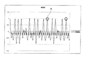
- FIG. 8 is a diagram for explaining a comparison pattern search method when a correlation value is used as the similarity of the data processing apparatus according to the present embodiment.
- the correlation value between the position command pulse of the operation template and the position command pulse in the target data range is taken.
- FIG. 8 is a graph showing the correlation values as an example of the cutting method. Among these, those having a correlation value of 0.999 or more are extracted as much as possible (circled portion indicated by symbol A in FIG. 8). The reason why the correlation value is 0.999 or more is extracted as shown in FIG. 6 because the relationship between the industrial robot 50 and the hand 25 and the mounting shelf 61 formed in the stocker 60 is Each shelf is different. Although not shown, since the stocker 60 is provided with a plurality of stockers, the positional relationship between the industrial robot 50 and each stocker is also different. Such a difference is caused as a difference in correlation values as shown in FIG.
- FIG. 9 is a graph showing the operation of the circled portion in FIG. If the comparison pattern of FIG. 9 is compared with the operation template of FIG. 4, they can be regarded as substantially the same operation (substantially the same operation) or similar operations.
- corresponding data (torque data as servo data in this embodiment) is associated with the template and the operation pattern described above.
- servo data is compared on the assumption that the same input condition (template and operation pattern) is the same.
- the input condition is the same because the template and the operation pattern in the position command are the same.
- the aging of the robot causes, for example, the life and deterioration of motors, bearings, etc., but by comparing the output of the robot body (servo data) against the same input conditions (position command) By examining the output difference, it becomes possible to determine the life of each part, the replacement time, and the like.
- FIG. 10 is a flowchart for explaining the overall operation of the robot information processing system according to the present embodiment. Next, the overall operation of the robot information processing system having the above configuration will be described with reference to the flowchart of FIG.
- the controller 30 outputs a command and servo data, which are information related to drive control of the servo system drive source, to the data processing device 40 as data S30 (step ST12).
- the data processor 40 collects the input command and servo data in units of about 20 msec, for example, and accumulates the collected data in the storage unit 44 (steps ST13 and ST14).
- the target industrial robot has a positional relationship facing the stocker 60 that accommodates the semiconductor wafer, and the robot hand 25 carries the semiconductor wafer into the stocker 60. Or carry out from the stocker.
- the robot processes the operations shown in FIG. 7 for each stage in the stocker shown in FIG. 6, but the robot hand may vary depending on the position of one or a plurality of stockers and the positional relationship of each stocker with the robot. The position of is slightly different. Specifically, the values on the vertical axis of the operation pattern shown in FIG.
- an operation pattern that is substantially the same as a slightly different operation pattern (a correlation value of 0.999 in the embodiment) is selected from a large amount (a huge amount) of data generated in time series. ) Is accurately and easily processed in a short time.
- the data processing device 40 creates a template that is a reference or reference operation pattern from a large amount of data generated in time series (step ST15).
- the data processing device 40 acquires a similarity (for example, a correlation value) and extracts a comparison pattern that is substantially the same operation pattern as the created template from the large amount of data described above (step ST16). That is, it is determined whether or not the template and the selected comparison pattern substantially match (step ST17). If they match (Yes in step ST17), the matching comparison pattern is extracted (step ST18) and stored. The data is stored in the unit 44 (step ST19). If it is determined in step ST17 that the template does not substantially match the selected comparison pattern (No in step ST17), the process returns to step ST16. Note that the creation of a template and an operation pattern (comparison pattern) is repeatedly executed.
- step ST20 the servo data between the extracted comparison pattern and the operation pattern as a template is compared (step ST20), and the secular change is confirmed (step ST21).
- the robot information processing system 10 including the data processing apparatus of this embodiment has the following configuration.
- the controller 30 can always output position data (or speed data) and servo data (torque, deviation, etc.), and the data processor 40 collects, stores, and accumulates a large amount of data generated in time series.
- the data processing apparatus 40 uses a position command (or speed command) as a template (reference data) for a desired operation pattern, for example, an operation pattern in which aging has been confirmed.
- the data processing apparatus 40 acquires the similarity with the past accumulated position command (or speed command) in the template, and extracts a matching (highly similar) operation pattern. Then, although it is optional, the servo data between the operation pattern templates with the extracted operation pattern is compared to confirm (check) the secular change.
- the production operation in the case of an industrial robot is basically a repetitive operation, so the same operation is always performed over time.
- the operations shown in FIGS. 5 and 7 are performed for each shelf of the plurality of placement shelves 61 of the stocker 60 and for the plurality of stockers. 5 and 7, the operation is to carry out the semiconductor wafer 70 and the like stored in the stocker 60.
- the hand 25 is used to remove the semiconductor wafer 70 and the like from the mounting shelf 61 of the stocker 60. There is an operation to carry in to the shelf.
- the velocity pattern template can be extracted as a single motion, the position pattern template can be extracted as a combined motion, and if multiple templates for each axis are used, long motion patterns can be compared with each other. Comparison with is possible.
- the operation of the industrial robot 50 is the operation shown in FIGS. 5 and 7, position data as a position command is adopted as the template and the pattern as the operation pattern. That is, it is a simple trapezoidal shape as shown in FIGS.
- the operation of the industrial robot 50 is complicated, it may be a complicated shape instead of a simple trapezoidal shape when represented by a position pattern. In such a case, only one operation, that is, the operation of step ST1 in FIG. 5 (FIG.
- step ST1 may be used to use the speed data as the speed command.
- the speed is increased by accelerating from the stopped state until reaching a predetermined operation, and then the speed is decreased to a certain speed and further to stop the operation. As a result, the speed becomes zero and the vehicle stops at a predetermined position. If this operation is graphed by the relationship between speed, position, and time, it can be expressed by a simple trapezoidal shape similar to FIGS.
- the operation pattern when an error occurs can also be used as a template to extract the same operation pattern from the past and compare changes in servo data.
- the cause of the error is related to the servo system. You can decide whether to do it.
- this data processing apparatus it is possible to check whether the servo data has changed from the same past operation using the operation pattern at the time of error as a template. As a result, it can be determined whether the error factor is caused by the servo system including the mechanism unit. For example, an operation pattern in which an error has occurred is templated from position (or velocity) data accumulated up to that point when a servo system error has occurred. The same operation pattern is extracted from the template in the past. Compare the past servo data of the same operation pattern with the servo data of the operation pattern in which an error occurred to check whether the cause of the error is due to the servo.
- the cycle time can be automatically derived. Register the cycle time operation pattern as a template. The past operation pattern is searched, the same operation pattern is extracted, and the cycle time is calculated.
- the data processing device 40 that collects and processes a large amount of data generated in time series includes the storage unit 44 that stores a large amount of input data. And a pattern extraction unit 45 for extracting a reference operation pattern template and a comparison pattern similar to the template from the data stored in the storage unit 44. Then, the pattern extraction unit 44 obtains the similarity between the template creation unit 451 that creates a template from the stored data, the comparison pattern selected from the stored data, and the template. A comparison pattern extraction unit 454 that extracts and stores a comparison pattern that becomes a similar operation pattern with the template based on the similarity acquired by the similarity acquisition unit 453.
- the data processing apparatus of the present embodiment it is possible to easily and accurately extract data to be compared from a large amount of data generated in time series.
- the similarity determination unit 453 of the pattern extraction unit 45 is configured to determine the similarity based on the correlation value between the template and the comparison pattern.
- the processing time may be short because the expression is not a high-order and complicated expression by obtaining the similarity using the correlation value. It does not have to be a computer with high processing capability, and it has the advantage of excellent versatility.
- the data generated in time series includes a command input for controlling the operation of the industrial robot 50 and an output from the industrial robot 50 that operates based on the command.
- the template and the comparison pattern are created from the command data.
- the pattern extraction part 45 is comprised so that the data corresponding to a template and a comparison pattern may be compared.
- the servo data includes torque data, and the pattern extraction unit 45 compares the torque data corresponding to the template and the comparison pattern.
- the data processing device 40 of the present embodiment there is a problem that it is difficult to set the same input condition in the existing technology.
- the same input condition template and There is an advantage in comparing the servo data on the assumption that the operation pattern is the same.
- the data processing device 40 having this configuration the following effects can be obtained. (1) It is not necessary to prepare an operation different from a normal production operation, such as a basic data acquisition operation, in order to see an aging change of a servo relation as in the existing technology. (2) Since the torque data of the production operation itself is inspected, analysis based on actual data is possible. (3) The following can be performed by the template function of this arbitrary specific operation.
- past data can be searched using the operation pattern at that time as a template, and compared with normal torque data, and it can be determined whether the servo system is the cause.
- the past operation pattern is extracted using the operation pattern at that time as a template, compared with past torque data, and there is no change in the mechanical system Can be judged.
- the method described in detail above can be formed as a program corresponding to the above procedure and executed by a computer such as a CPU.
- the operation at the time when aging has not progressed is selected as the template.
- the present invention is not limited to this.
- a cluster of continuous data of axis position commands (or speed commands) for which the template creation unit 451 wants to check (check) the servo data change from the past accumulated in the storage unit 44. May be used as a template.
- Such a program can be configured to be accessed by a recording medium such as a semiconductor memory, a magnetic disk, an optical disk, a floppy (registered trademark) disk, or the like, and to execute the program by a computer in which the recording medium is set.
- a recording medium such as a semiconductor memory, a magnetic disk, an optical disk, a floppy (registered trademark) disk, or the like.
Landscapes
- Engineering & Computer Science (AREA)
- Robotics (AREA)
- Mechanical Engineering (AREA)
- Physics & Mathematics (AREA)
- General Physics & Mathematics (AREA)
- Automation & Control Theory (AREA)
- Manipulator (AREA)
- General Factory Administration (AREA)
- Testing And Monitoring For Control Systems (AREA)
- Numerical Control (AREA)
Abstract
本願は、時系列に発生する多量のデータの中から、比較したいデータを精度良く、容易に抽出することすることが可能なデータ処理装置およびデータ処理方法を提供する。例えば、データ処理装置(40)は、入力される時系列に発生する多量のデータを格納する記憶部(44)と、記憶部(44)に蓄積されたデータの中から基準となる動作パターンのテンプレートと、このテンプレートに類似する比較パターンとをそれぞれ抽出するパターン抽出部(45)と、を有し、パターン抽出部(45)は、記憶部に記憶されたデータの中からテンプレートを作成するテンプレート作成部(451)と、記憶部に記憶されたデータの中から選択された比較パターンと、テンプレートとの類似度を取得する類似度取得部(453)と、類似度取得部により取得した類似度に基づいて、テンプレートと類似動作パターンとなる比較パターンを抽出して格納する比較パターン抽出部(454)と、を含む。
Description
本発明は、時系列に発生する多量のデータを処理するデータ処理装置およびデータ処理方法に関するものである。
時系列に発生する多量のデータを処理するデータ処理方法は、たとえば、産業用ロボットの故障診断方法に利用されている(特許文献1参照)。
一般に、産業用ロボットの故障診断方法では、サーボモータを駆動源とする産業用ロボットのデータを収集して抽出し、所定の処理を行い、そのデータを用いて産業用ロボットの経年変化を監視している。
具体的には、機械的な部分である機構部の経年変化を監視するために、たとえば、カセット内に収納されている半導体ウェハ等を産業用ロボットのハンドで搬入、搬出する動作等のように、ある決められた動作を定期的に実行させて、そのときのデータを取得し、導入当初の基準データと比較して異常であれば警報を発するシステムとして構成されている。
しかしながら、従来は、基準データの収集動作を通常の生産動作とは別に用意して実行している。そのため、通常の生産運転と速度などの動作条件、動作パターンなど異なるので、経年変化として捉える解析も正確でない。すなわち、時系列に発生する多量のデータの中から、動作条件、環境条件、動作パターン等の前提条件が基準となる動作パターンのデータと同じ比較したいデータを精度良く、容易に抽出することが困難であった。
本発明の目的は、時系列に発生する多量のデータの中から、比較したいデータを精度良く、容易に抽出することが可能なデータ処理装置およびデータ処理方法を提供することにある。
本発明の第1の観点は、時系列に発生する多量のデータを収集して処理するデータ処理装置であって、入力される前記データを格納する記憶部と、前記記憶部に蓄積された前記データの中から、基準となる動作パターンのテンプレートと、当該テンプレートに類似する比較パターンとをそれぞれ抽出するパターン抽出部と、を有し、前記パターン抽出部は、前記データの中から前記テンプレートを作成するテンプレート作成部と、前記データの中から選択された比較パターンと、前記テンプレートとの類似度を取得する類似度取得部と、前記類似度取得部により取得した類似度に基づいて、前記テンプレートと類似動作パターンとなる比較パターンを抽出して格納する比較パターン抽出部と、を含む。
このデータ処理装置によれば、時系列に発生する多量のデータの中から、比較したいデータを精度良く、容易に抽出することすることができる。
本発明は、前記パターン抽出部の前記類似度判別部は、前記テンプレートと前記比較パターン間の相関値に基づいて前記類似度を判別するように構成してもよい。
この構成によれば、類似度を相関値を用いて求めることで、式が高次で複雑な式でないことから、処理時間が短くてよく、高い処理能力を持ったコンピュータでなくともよく、汎用性に優れている。
本発明は、前記時系列に発生するデータは、産業用ロボットを動作制御するために入力される指令データと、当該指令データに基づいて動作した前記産業用ロボットから出力されるサーボデータとを含み、前記テンプレートおよび前記比較パターンは前記指令データの中から作成され、前記パターン抽出部は、前記テンプレートおよび前記比較パターンの前記対応するデータを比較する構成にしてもよい。好適には、前記サーボデータは、トルクデータを含み、前記パターン抽出部は、前記テンプレートおよび前記比較パターンの対応する前記トルクデータを比較する。
この構成によれば、既存技術では同じ入力条件に設定することが難しいという問題があったが、本構成によれば、同じ入力条件(テンプレートと動作パターン)が同じであるという前提で、このサーボデータを比較することに利点がある。
本発明の第2の観点は、系列に発生する多量のデータを収集して処理するデータ処理方法であって、入力される前記データを記憶部に格納する記憶ステップと、前記記憶部に蓄積された前記データの中から、基準となる動作パターンのテンプレートと、当該テンプレートに類似する比較パターンとをそれぞれ抽出するパターン抽出ステップと、を有し、前記パターン抽出ステップは、前記データの中から前記テンプレートを作成するテンプレート作成ステップと、前記データの中から選択された比較パターンと、前記テンプレートとの類似度を取得する類似度取得ステップと、前記類似度取得ステップにより取得した類似度に基づいて、前記テンプレートと類似動作パターンとなる比較パターンを抽出して格納する比較パターン抽出ステップと、を含む。
本発明によれば、時系列に発生する多量のデータの中から、動作条件、環境条件、動作パターン等の前提条件が基準データと同じ比較したいデータを精度良く、容易に抽出することが可能となる。
以下、本発明の実施形態を図面に関連付けて説明する。
以下の実施形態においては、産業機械として産業用ロボットを動作制御するために入力される指令データおよび指令データに基づいて動作した産業用ロボットから出力されるサーボデータを収集するデータ処理装置を含むロボット情報処理システムを例に説明する。
以下の実施形態においては、産業機械として産業用ロボットを動作制御するために入力される指令データおよび指令データに基づいて動作した産業用ロボットから出力されるサーボデータを収集するデータ処理装置を含むロボット情報処理システムを例に説明する。
図1は、本発明の実施形態に係るロボット情報処理システムの概要を示すブロック図である。
本ロボット情報処理システム10は、図1に示すように、ロボット本体20、ロボット本体20の動作を制御するコントローラ30、およびデータ処理装置40を含んで構成されている。
[ロボット本体およびコントローラの構成および機能]
本実施形態において、ロボット本体20およびコントローラ30により、たとえば半導体ウェハや液晶表示パネル用ガラス基板(以下、半導体ウェハ等とする)を搬送する産業用ロボット50として構成される。コントローラ30は、ロボット本体20の動作を制御し、ロボット本体20の通常の生産での入力データとしての指令データ(位置や速度)と出力データとしてのサーボデータ(トルクや偏差など)をデータ処理装置40に時系列に出力する。すなわち、指令データおよびサーボデータは時系列に発生する多量のデータである。さらに、入力データとしての指令データ(位置や速度)はプログラム等によって作成されるデータであり、経年変化の影響を受けないデータである。一方、出力データとしてのサーボデータ(トルクや偏差など)は産業用ロボットを構成する機械的な部分である機構部等の経年変化を受けやすいデータである。
本実施形態において、ロボット本体20およびコントローラ30により、たとえば半導体ウェハや液晶表示パネル用ガラス基板(以下、半導体ウェハ等とする)を搬送する産業用ロボット50として構成される。コントローラ30は、ロボット本体20の動作を制御し、ロボット本体20の通常の生産での入力データとしての指令データ(位置や速度)と出力データとしてのサーボデータ(トルクや偏差など)をデータ処理装置40に時系列に出力する。すなわち、指令データおよびサーボデータは時系列に発生する多量のデータである。さらに、入力データとしての指令データ(位置や速度)はプログラム等によって作成されるデータであり、経年変化の影響を受けないデータである。一方、出力データとしてのサーボデータ(トルクや偏差など)は産業用ロボットを構成する機械的な部分である機構部等の経年変化を受けやすいデータである。
本形態のコントローラ30は、後述するが、産業用ロボット50のロボットアーム20ARMの駆動源としてサーボモータを使用しており、コントローラ30から指令データをサーボモータに出力し、サーボモータに取り付けられているエンコーダから出力されるサーボデータとしての検出値をフィードバックさせて、サーボモータの回転位置などを目標値(指令データ)に一致させることにより、目標値(指令データ)の変化に追従させている。
ロボット本体20は、ロボット基台21、アーム基軸部22、第1アーム部23、第2アーム部24、およびたとえばハンド25を有する。
ロボット本体20において、ロボット基台21には、図中に設定した直交座標系のZ軸方向(図では上下方向)に延びるアーム基軸部22が昇降および回転自在に配置されている。
アーム基軸部22の上端部には、第1アーム部23の基端部が固定されている。第1アーム部23の先端部には、第2アーム部24の基端部が回転自在に取り付けられている。第2アーム部24の先端部には、搬送対象物である半導体ウェハ等を保持して搬送するハンド25が回転自在に配置されている。
このハンド25は、たとえば半導体ウェハ等の搬送対象物がその上に載置されるように構成される。ハンド25は、その上に載置された半導体ウェハ等の搬送対象物を解放可能に保持することができるように形成されている。
第2アーム部24は、その基端部にて、第1アーム部23の先端部に回転自在に設けられた第2アーム回転軸26に固定的に取り付けられている。ハンド25は、その基端部にて、第2アーム部24の先端部に回転自在に配置されたハンド(Hand)軸27に固定的に取り付けられている。
このようにロボット本体20のロボットアーム20ARMは、アーム基軸部22、第1アーム部23、第2アーム部24、ハンド25、第2アーム回転軸26、およびハンド軸27を含んでいる。この種のロボットアーム20ARMは、スカラ型水平多関節アームと呼ばれ、ロボットの制御部としてのコントローラ30によりロボットアーム20ARMの動作を制御することにより、ハンド25をX軸、Y軸、およびZ軸方向の所望の位置まで移動するが可能である。
ロボット本体20は、第1アーム部23を回転駆動する第1アーム駆動部201、第2アーム部24を回転駆動する第2アーム駆動部202、ハンド軸27を回転駆動するハンド軸駆動部203、およびアーム基軸部22をZ軸方向に昇降駆動する昇降駆動部204を有している。
第1アーム駆動部201は、ロボット基台21の内部空間に配置され、エンコーダを内蔵するサーボモータおよびその動力伝達機構を含む。第2アーム駆動部202は、第1アーム部23の内部空間に配置され、エンコーダを内蔵するサーボモータおおよびその動力伝達機構を含む。ハンド軸駆動部203は、第2アーム部24の内部空間に配置され、エンコーダを内蔵するサーボモータおよびその動力伝達機構を含む。
動力伝達機構には、たとえば減速機を備え、サーボモータの動力が減速機の入力側に伝達され、そのトルクが予め定める増幅比で増幅され、その回転速度が予め定める減速比で減速されて、減速機の出力側から出力される。このようにして減速機の出力側から出力された動力によって、アーム基軸部22、第2アーム回転軸26、およびハンド軸27のそれぞれが回転駆動される。これにより、第1アーム部23、第2アーム部24、およびハンド25のそれぞれが回転駆動される。
昇降駆動部204は、ロボット基台21の内部に配置されており、角変位量を調整可能なモータを用いたボールねじ機構によって実現される。たとえば、昇降駆動部204は、ボールネジと、このボールネジに螺合される螺合体と、ボールネジを回転駆動するモータと、を含み、螺合体にアーム基軸部22が固定される。昇降駆動部204のモータには、エンコーダを内蔵するサーボモータが用いられる。
このような構成を有するロボット本体20においては、第1アーム駆動部201によってアーム基軸部22がロボット基台21に対して回転軸線RX1周りに回転駆動される。これにより、第1アーム部23が、ロボット基台21に対して回転軸線RX1周りに回転駆動される。
第2アーム駆動部202によって、第2アーム回転軸26が、第1アーム部23に対して回転軸線RX2周りに回転駆動される。これにより、第2アーム部24が、第1アーム部23に対して回転軸線RX2周りに回転駆動される。
ハンド軸駆動部203によって、ハンド軸27が、第2アーム部24に対して回転軸線RX3周りに回転駆動される。これにより、ハンド25が、第2アーム部24に対して回転軸線RX3周りに回転駆動される。
ロボット本体20では、基本的に、通常の生産動作において、第1アーム駆動部201、第2アーム駆動部202、ハンド軸駆動部203、および昇降駆動部204の各サーボモータは、コントローラ30により入力される位置または速度指令に応じて駆動され、トルクや偏差などのサーボデータがコントローラ30に時系列に出力される。
コントローラ30は、制御対象の第1アーム駆動部201、第2アーム駆動部202、ハンド軸駆動部203、および昇降駆動部204に対して位置または速度指令を出力し、各駆動部のサーボモータのエンコーダから、各サーボモータの角度位置を取得することによって、各駆動部をフィードバック制御する。これにより、ハンド25を目的位置に精度良く位置合わせすることが可能となる。
コントローラ30は、通常の生産動作でのロボット本体20のサーボ系駆動源(サーボモータ)の駆動制御に関する情報である指令(位置または速度)およびサーボデータ(トルク、偏差など)の時系列に発生する多量のデータS30をデータ処理装置40に出力する。ここで、指令データとしての位置データ(または速度データ)は、産業用ロボット50を動作制御するために入力される入力データであり、コントローラ30からロボット本体20の対応する駆動部に出力されるデータである。サーボデータは、指令データに基づいて動作制御する産業用ロボット50から出力される出力データであり、ロボット本体20の駆動部からコントローラ30に出力されるデータである。コントローラ30は、指令データとしての位置データ(または速度データ)および出力データとしてのサーボデータ(トルク、偏差など)を、ロボット本体20の通常の生産動作にあわせてデータ処理装置としてのCPC40に出力できるように構成されている。なお、本実施形態では、コントローラ30から上記した位置データ(または速度データ)およびサーボデータ(トルク、偏差など)を時系列に出力するようにしている。
コントローラ30は、たとえばCPU(Central Processing Unit)31およびメモリ32を含んで構成される。CPU31は、メモリ32に格納される動作プログラムを実行してロボット本体20を制御する。メモリ32には、ロボット本体20の動作を制御するための教示点に関するデータ(位置データ)を格納することもでき、メモリ32に格納された教示点に関するデータに基づいて、ハンド25が所定の位置へと動かされる。また、メモリ32には、ハンド25の形状・寸法に関するデータ、ハンド25に保持された半導体ウェハ等の形状・寸法に関するデータも格納される。
以上、ロボット本体20およびコントローラ30の構成および機能について説明した。次に、本実施形態に係るデータ処理装置の構成および機能について詳細に説明する。
[データ処理装置の構成および機能]
本実施形態に係るデータ処理装置40は、コントローラ30からロボット本体20の通常の生産動作にあわせて出力される、サーボ系駆動源の駆動制御に関する情報である位置データ(または速度データ)およびサーボデータ(トルク、偏差など)を収集して所定の処理を施し、たとえば時系列に発生する多量のデータの中から、動作条件、環境条件、動作パターン等の前提条件が基準データと略同じ比較したいデータを精度良く、容易に抽出する機能を有する。
本実施形態に係るデータ処理装置40は、コントローラ30からロボット本体20の通常の生産動作にあわせて出力される、サーボ系駆動源の駆動制御に関する情報である位置データ(または速度データ)およびサーボデータ(トルク、偏差など)を収集して所定の処理を施し、たとえば時系列に発生する多量のデータの中から、動作条件、環境条件、動作パターン等の前提条件が基準データと略同じ比較したいデータを精度良く、容易に抽出する機能を有する。
本実施形態に係るデータ処理装置40は、基本的に、コントローラ30から入力される時系列に発生する多量のデータに所定の処理を実施しており、位置データ (または速度データ)およびサーボデータを格納する記憶部、および記憶部に蓄積されたデータの中から基準となる動作パターンのテンプレート(基準データ)と、このテンプレートに類似する比較パターン(比較したいデータ)とを抽出するパターン抽出部と、を含んで構成される。
データ処理装置40のパターン抽出部は、時系列に発生する多量のデータの中で、入力データとしての指令データ、すなわち、位置データ(または速度データ)に基づいて、基準データとしての動作パターンのテンプレートを作成する機能と、時系列に発生する多量のデータの中から選択された比較したいデータとしての比較パターンと、作成したテンプレートとの類似度を取得する類似度取得機能と、取得した類似度に基づいて、テンプレートと類似動作パターンとなる比較パターンを抽出して格納する比較パターン抽出機能と、を含む。
パターン抽出部の類似度判別機能は、たとえばテンプレートと比較パターン間の相関値に基づいて類似度を判別する。このように、類似度を相関値を用いて求めることで、式が高次で複雑な式でないことから、処理時間が短くてよく、高い処理能力を持ったコンピュータでなくともよく、汎用性に優れている。
本実施形態においては、時系列に発生する多量のデータは、産業用ロボット本体20を動作制御するために入力される指令データと、指令に基づいて動作した産業用ロボット本体20からの出力データとを含み、テンプレートおよび比較パターンは指令データの中から作成される。そして、パターン抽出部は、テンプレートおよび比較パターンの対応するデータを比較する。後述するように、テンプレートおよび比較パターンには、それぞれ対応するサーボデータが関連付けされており、パターン抽出部は、テンプレートおよび比較パターンの対応するサーボデータを比較する。すなわち、本実施形態では、テンプレートと比較パターンに対応するサーボデータを比較することで、経年変化の影響を数値化することが可能となっている。サーボデータは、たとえばトルクデータを含み、パターン抽出部は、テンプレートおよび比較パターンの対応するトルクデータを比較する。
図2は、本実施形態に係るデータ処理装置の構成例を示すブロック図である。図2のデータ処理装置40は、パーソナルコンピュータ(PC)等により構成され、制御部41、入力部42、出力部43、記憶部44、パターン抽出部45を有している。
制御部41は、CPUおよびROM,RAM、外部記憶装置などの各種メモリを含んで構成され、各部の制御、データの一時的な格納制御、データの転送制御等を行う。
入力部42は、キーボードやマウスなどによりユーザが入力した情報を受信し、受信した情報を制御部41に供給する。また、ロボット本体20から出力されたデータも制御部41によりここで受信して記憶部44に送られる。
出力部43は、CRT(Cathode Ray Tube)やLCD(Liquid Crystal Display device)などのディスプレイへの表示を行ったり、プリンタによる印刷を行う。
記憶部44は、各種設定データ(プログラム等)、時系列に発生する多量のデータである、産業用ロボット本体20に供給された入力データ(位置、速度指令)、また産業用ロボット本体20から出力される出力データとしてのサーボデータ(トルクデータ、偏差データ等)、および比較した結果のデータを記憶する。
パターン抽出部45は、産業用ロボット本体20に供給された入力データ(位置指令、速度指令)からテンプレートを作成するとともに、動作条件、環境条件、動作パターン等の前提条件がテンプレート(基準データ)と略同一の動作パターン(比較パターン)を抽出する。このパターン抽出部45は、テンプレート作成部451、比較(動作)パターン作成部452、類似度取得部453、および比較パターン抽出部(比較部)454を有する。
テンプレート作成部451は、記憶部44に蓄積された時系列に発生する多量のデータの中から基準となる動作パターンのテンプレートを作成する。比較パターン作成部452は、時系列に発生する多量のデータの中から、作成されたテンプレートと比較する対象としての比較パターン(動作パターン)を作成する。
類似度取得部453は、時系列に発生する多量のデータから選択された比較パターンと、テンプレートとの類似度を取得する。ここで、上述しているように、テンプレートおよび比較パターン(動作パターン)は、入力データとしての指令(位置や速度)はプログラム等によって作成されるデータであり、経年変化の影響を受けないデータである。したがって、テンプレートと比較パターン(動作パターン)は、動作条件、環境条件、動作パターン等の前提条件が略一致していると考えられる。比較パターン抽出部454は、類似度取得部453により取得した類似度に基づいて、テンプレートと類似動作パターンとなる比較パターンを抽出して、たとえば制御部41の制御の下、記憶部44に格納する。
次に、このパターン抽出部45における動作パターンのテンプレート化と略同一の動作パターンである比較パターンを抽出する処理を、データ例に関連付けて説明する。ここでは、テンプレートと比較パターン間の相関値に基づいて類似度を判別する処理を例に説明する。
図3は、本実施形態に係るデータ処理装置におけるコントローラからの取得データの記憶部への蓄積の一例を示す図である。図4は、動作テンプレートの作成の一例を示す図である。
[コントローラからの取得データの蓄積]
データ処理装置40は、コントローラ30から取得した位置指令とトルクデータを、図3に示すような形態で記憶部44に蓄積する。図3には、データを収集した時刻、各時刻ごとの入力データとしての位置指令パルス、位置指令パルスに対応する出力データとしての出力トルクが明記されている。位置指令パルスは、各モータに取り付けられているエンコーダの出力数(パルス数)で示している。また、トルクデータは電流相当値であり、モータへ供給する電流値に比例する内部制御値である。図3の例では、約20msec単位での取得している位置指令、トルクデータの一部を抜粋したものである。なお、Hand、Z、TH….はロボットの動作軸の名称に対応しており、たとえば動作軸Handは図1のハンド軸27に相当し、動作軸ZはZ軸方向に昇降駆動されるアーム基軸部22のアーム基軸に相当する。また、動作軸THは、たとえば図1の第2アーム回転軸26に相当する。
データ処理装置40は、コントローラ30から取得した位置指令とトルクデータを、図3に示すような形態で記憶部44に蓄積する。図3には、データを収集した時刻、各時刻ごとの入力データとしての位置指令パルス、位置指令パルスに対応する出力データとしての出力トルクが明記されている。位置指令パルスは、各モータに取り付けられているエンコーダの出力数(パルス数)で示している。また、トルクデータは電流相当値であり、モータへ供給する電流値に比例する内部制御値である。図3の例では、約20msec単位での取得している位置指令、トルクデータの一部を抜粋したものである。なお、Hand、Z、TH….はロボットの動作軸の名称に対応しており、たとえば動作軸Handは図1のハンド軸27に相当し、動作軸ZはZ軸方向に昇降駆動されるアーム基軸部22のアーム基軸に相当する。また、動作軸THは、たとえば図1の第2アーム回転軸26に相当する。
[動作テンプレートの登録]
データ処理装置40のパターン抽出部45は、テンプレート作成部451において記憶部44に蓄積されている過去からのサーボデータ変化を確認(チェック)したい軸の位置指令(または速度指令)の連続したデータの固まりを、たとえば図4に示すようなテンプレートTMPとして選択する。具体的には、テンプレートTMPは、産業用ロボット50が初めて生産に供されるときは試運転が完了した時点、または産業用ロボットの動力伝達機構に修理や部品交換が施されときは通常運転が可能になった時点でもデータの中から作成される。換言すれば、動力伝達機構等に経年劣化が進行していないときに基準データを取得する。このように、基準データは、経年劣化が進んでいなければ、いつの時点で取得しても良いので、基準データ取得段階は厳密に定める必要はない。図4において、横軸は時間を示し、縦軸はハンド25の移動距離を相対的な値として示している。図4は、あくまでも一例であって、図3のHand軸の位置指令パルスで連続しデータかたまりを動作テンプレートTMPとして登録したもので、それを分かりやすくするためにグラフ表示したものである。
データ処理装置40のパターン抽出部45は、テンプレート作成部451において記憶部44に蓄積されている過去からのサーボデータ変化を確認(チェック)したい軸の位置指令(または速度指令)の連続したデータの固まりを、たとえば図4に示すようなテンプレートTMPとして選択する。具体的には、テンプレートTMPは、産業用ロボット50が初めて生産に供されるときは試運転が完了した時点、または産業用ロボットの動力伝達機構に修理や部品交換が施されときは通常運転が可能になった時点でもデータの中から作成される。換言すれば、動力伝達機構等に経年劣化が進行していないときに基準データを取得する。このように、基準データは、経年劣化が進んでいなければ、いつの時点で取得しても良いので、基準データ取得段階は厳密に定める必要はない。図4において、横軸は時間を示し、縦軸はハンド25の移動距離を相対的な値として示している。図4は、あくまでも一例であって、図3のHand軸の位置指令パルスで連続しデータかたまりを動作テンプレートTMPとして登録したもので、それを分かりやすくするためにグラフ表示したものである。
図5は、本実施形態に係るデータ処理装置においてテンプレートを作成する場合のロボット本体のハンドの動作例を示す図である。図6は、ロボット本体におけるハンドと半導体ウェハ等(搬送対象物)を格納するストッカを対応付けて示す図である。図7は、図5に対応するハンドの動作をハンドとストッカを用いて具体的に示す図である。図6および図7において、60は半導体ウェハ等(搬送対象物)を格納するストッカを、70は搬送対象物の一例では半導体ウェハ等を示している。また、図7において、61はストッカ60内に形成されている複数の載置棚のある一の棚を示している。なお、図7は、ロボットが半導体ウェハ等をストッカから搬出する動作を示している。ハンドのZ軸方向、図では下から上に向かって移動する動作を含む。
図5において、ステップST1~ST4は図4のテンプレートのグラフに付した符号ST1~ST4に対応している。ステップST1で、第1の位置PT1にあるハンド25をストッカ60の方向に延ばしを開始して、図7(A)に示すように、搬送すべき半導体ウェハ70等を保持できる第2の位置PT2に水平移動させる。この状態がステップST2である。次に、図7(B)に示すように、第2の位置PT2においてハンド25で半導体ウェハ70等の下面部を吸着等の方法で保持し、図7(C)に示すように、第2の位置PT2でZ軸方向にアーム基軸部22の上昇(垂直移動)を開始する。そして、ステップST3において、図7(C)に示すように、Z軸方向の第3の位置PT3で上昇を完了する。次いで、ハンド25をストッカ60から離れる方向に水平移動させ、第4の位置PT4まで戻して、一連の動作が完了する。
[比較したい日時のデータ範囲から上記動作テンプレートと同じものをサーチ]
次に、比較したい日時のデータ範囲から上記動作テンプレートと同じ動作パターン(比較パターン)をサーチする。
次に、比較したい日時のデータ範囲から上記動作テンプレートと同じ動作パターン(比較パターン)をサーチする。
図8は、本実施形態に係るデータ処理装置の類似度として相関値を用いた場合の比較パターンのサーチ方法を説明するための図である。この例では、動作テンプレートの位置指令パルスと対象となるデータ範囲の中の位置指令パルス間の相関値をとる。切り出す方法の一つの例として相関値をグラフ化したものが図8である。この中からできるだけ相関値が0.999以上のものを抽出する(図8中符号Aで示す丸部分)。なお、相関値が0.999以上のものを抽出することにしているのは、図6に示すように、産業ロボット50およびハンド25とストッカ60に形成された載置棚61との関係は、各棚ごとに異なっている。また、図示していないが、ストッカ60は複数のストッカが配置されているため、産業用ロボット50と各ストッカとの位置関係も異なっている。このような違いが、図8に示すような相関値の違いとなって生じている。
[切り出した動作]
図9は、図8中の丸部分の動作をグラフ化して示す図である。図9の比較パターンと図4の動作テンプレートとを比較すると、両者は実質的にまったく同じ動作(略同一の動作)あるいは類似の動作とみなすことができる。
図9は、図8中の丸部分の動作をグラフ化して示す図である。図9の比較パターンと図4の動作テンプレートとを比較すると、両者は実質的にまったく同じ動作(略同一の動作)あるいは類似の動作とみなすことができる。
[テンプレートと抽出した(切り出した)動作パターンのトルクデータを比較]
上述したように、動作テンプレートと抽出した一致する動作パターン(比較パターン)のサーボデータ、たとえばトルクデータを比較する。これにより、たとえばロボット本体20のサーボ系駆動部のいわゆる経年変化を確認(チェック)することが可能である。換言すれば、期間の開いた同じ動作パターンが抽出できたので、その間のトルクデータを比較することにより、経年変化を確認(チェック)する。なお、比較方法は、特許文献1に記載された方法等、種々の方法を採用可能である。
上述したように、動作テンプレートと抽出した一致する動作パターン(比較パターン)のサーボデータ、たとえばトルクデータを比較する。これにより、たとえばロボット本体20のサーボ系駆動部のいわゆる経年変化を確認(チェック)することが可能である。換言すれば、期間の開いた同じ動作パターンが抽出できたので、その間のトルクデータを比較することにより、経年変化を確認(チェック)する。なお、比較方法は、特許文献1に記載された方法等、種々の方法を採用可能である。
すなわち、上述したテンプレートと動作パターンには、それぞれ、対応するデータ(本実施形態ではサーボデータとしてのトルクデータ)が関連付けされている。従来は、同じ入力条件に設定することが難しいという問題があったが、本実施形態によれば、同じ入力条件(テンプレートと動作パターン)が同じであるという前提で、このサーボデータを比較することに利点がある。
このように、本実施形態では、上記したとおり、位置指令におけるテンプレートと動作パターンとが同一であることによって、入力条件が同じとなる。そのときのロボットからの出力、すなわち、サーボデータを比較することで、ロボットの経年変化を確認することが可能となり、故障診断を行うことが可能となる。具体的には、ロボットの経年変化によって、たとえば、モータ、軸受等の寿命、劣化等が生じるが、同じ入力条件(位置指令)に対して、ロボット本体の出力(サーボデータ)を比較することで、出力差を調べて、各部品の寿命や交換時期等を判断することが可能となる。
[ロボット情報処理システムの全体の動作]
図10は、本実施形態に係るロボット情報処理システムの全体の動作を説明するためのフローチャートである。次に、上記構成を有するロボット情報処理システムの全体の動作をデータ処理装置40の動作を中心に、図10のフローチャートに関連付けて説明する。
図10は、本実施形態に係るロボット情報処理システムの全体の動作を説明するためのフローチャートである。次に、上記構成を有するロボット情報処理システムの全体の動作をデータ処理装置40の動作を中心に、図10のフローチャートに関連付けて説明する。
本実施形態のロボット情報処理システム10においては、通常の生産動作での産業用ロボットから指令(ロボットに入力するデータ)とサーボデータ(ロボットから出力されるデータ)を取得することが可能である。作業用ロボットの通常の生産動作において(ステップST11)、コントローラ30がサーボ系駆動源の駆動制御に関する情報である指令およびサーボデータをデータS30としてデータ処理装置40へ出力する(ステップST12)。これにより、データ処理装置40は、入力される指令およびサーボデータを、たとえば約20msec単位で収集し、収集したデータを記憶部44に蓄積する(ステップST13、ST14)。
たとえば、対象としている産業用ロボットは、たとえば図6および図7に示すように、半導体ウェハを収容するストッカ60と対向する位置関係にあり、ロボットのハンド25が半導体ウェハをストッカ60内に搬入し、またはストッカから搬出する動作を行う。
図7に示す動作をロボットは、図6に示すストッカ内の各段に対して処理するが、1つまたは複数配置されたストッカの位置や各ストッカのロボットとの位置関係等により、ロボットのハンドの位置が微妙に異なってくる。具体的には、図4等に示す動作パターンの縦軸の値が微妙に異なってくる。そのために、本実施形態に係るデータ処理装置40では、時系列に発生する多量(膨大)のデータの中から、微妙に異なる動作パターンと略同一の動作パターン(実施形態では相関値が0.999)を取り出すことを、精度良く、容易に短時間で処理することを可能とする。
図7に示す動作をロボットは、図6に示すストッカ内の各段に対して処理するが、1つまたは複数配置されたストッカの位置や各ストッカのロボットとの位置関係等により、ロボットのハンドの位置が微妙に異なってくる。具体的には、図4等に示す動作パターンの縦軸の値が微妙に異なってくる。そのために、本実施形態に係るデータ処理装置40では、時系列に発生する多量(膨大)のデータの中から、微妙に異なる動作パターンと略同一の動作パターン(実施形態では相関値が0.999)を取り出すことを、精度良く、容易に短時間で処理することを可能とする。
具体的には、データ処理装置40は、時系列に発生する多量のデータの中から、参照または基準となる動作パターンであるテンプレートを作成する(ステップST15)。次に、データ処理装置40は、上記した多量のデータの中から、作成したテンプレートと略同一の動作パターンである比較パターンを類似度(たとえば相関値)を取得して抽出する(ステップST16)。すなわち、テンプレートと選択した比較パターンとが略一致するか否かを判別し(ステップST17)、一致する場合には(ステップST17のYes)、その一致する比較パターンを抽出し(ステップST18)、記憶部44に格納する(ステップST19)。ステップST17において、テンプレートと選択した比較パターンとが略一致しないと判別した場合には(ステップST17のNo)、ステップST16の処理に戻る。なお、テンプレートや動作パターン(比較パターン)の作成は、繰り返し実行される。
そして、たとえば抽出した比較パターンとテンプレートとした動作パターン間のサーボデータを比較し(ステップST20)、経年変化を確認する(ステップST21)。
以上説明したように、本実施形態のデータ処理装置を含むロボット情報処理システム10は以下の構成を有する。位置データ(または速度データ) およびサーボデータ(トルク、偏差など)を常時出力できるコントローラ30を有し、データ処理装置40は、時系列に発生する多量のデータを収集、保存、蓄積する。データ処理装置40は、所望する動作パターン、たとえば経年変化を確認した動作パターンを位置指令(または、速度指令)を使用してテンプレート(基準データ)とする。データ処理装置40は、テンプレートにて過去の蓄積された位置指令(または速度指令)と類似度を取得し、一致する(類似度の高い)動作パターンを抽出する。そして、任意ではあるが、抽出した動作パターンとの動作パターンのテンプレート間のサーボデータを比較し経年変化を確認(チェック)する。
その結果、本実施形態のデータ処理装置40によれば、過去と現在の任意の動作パターン間で、それに付随するトルクデータ、偏差データなどが解析可能になる。産業用ロボットの場合の生産運転は繰り返し動作が基本なので経時的に必ず同じ動作がある。たとえば、図5および図7に示すような動作を、ストッカ60の複数の載置棚61の各棚ごと、また、複数のストッカに対して実施する。また、図5および図7では、ストッカ60に格納された半導体ウェハ70等を搬出する動作であるが、逆に、ハンド25を用いて、半導体ウェハ70等をストッカ60の載置棚61の所定の棚に搬入する動作がある。
速度パターンのテンプレートは単動作、位置パターンのテンプレートでは組み合わせ動作の抽出が可能になり、また、各軸の複数のテンプレートを使用すれば、長い動作パターン同士の比較も可能になり、任意の動作パターンでの比較が可能である。具体的には、本実施形態では、産業用ロボット50の動作は図5および図7に示す動作であるので、テンプレートおよび動作パターンとしてのパターンは、位置指令としての位置データを採用している。すなわち、図4および図9に示すような単純な台形形状である。産業用ロボット50の動作が複雑な場合には、位置パターンで表した場合には単純な台形形状ではなく、複雑な形状となる場合がある。このような場合には、1つの動作、すなわち、図5(図7)のステップST1の動作だけを用いて、速度指令としての速度データを用いてもよい。すなわち、ステップST1の動作を速度指令で考えると、停止した状態から所定の動作になるまで加速されることで速度が増加し、その後、一定の速度、さらに、動作を停止させるために速度を減少させて、速度がゼロとなり、所定の位置で停止することになる。この動作を速度と位置と時間との関係でグラフ化すれば、図4および図9と同じような単純な台形形状で表すことが可能となる。
また、この機能を利用すればエラーが発生したときの動作パターンもテンプレートにして、過去にさかのぼって同じ動作パターンを抽出し、サーボデータの変化の比較が可能になり、エラー要因がサーボ系に関係するか判断できる。
また、本データ処理装置によれば、エラー発生時の動作パターンをテンプレートにして過去の同じ動作からサーボデータが変化していないか確認できる。この結果、エラー要因が機構部を含めたサーボ系に起因するものかどうか判断できる。たとえば、サーボ系のエラーが発生したときにその時点までに蓄積していた位置(または速度)データからエラーが発生した動作パターンをテンプレート化する。そのテンプレートから過去にさかのぼって同じ動作パターンを抽出する。過去の同じ動作パターンのサーボデータとエラーが発生した動作パターンのサーボデータと比較してエラー要因がサーボに起因するものかチェックする。産業用ロボットではサイクルタイムの把握が求められる場合が多いがこの機能を応用するとサイクルタイムが自動的に導き出すことができる。サイクルタイムの動作パターンをテンプレートとして登録する。過去の動作パターンをサーチして同じ動作パターンを抽出してサイクルタイムを算出する。
以上説明したように、本実施形態のデータ処理装置40によれば、時系列に発生する多量のデータを収集して処理するデータ処理装置40は、入力される多量のデータを格納する記憶部44と、記憶部44に蓄積されたデータの中から、基準となる動作パターンのテンプレートと、テンプレートに類似する比較パターンとをそれぞれ抽出するパターン抽出部45と、を有する。そして、パターン抽出部44は、記憶されたデータの中からテンプレートを作成するテンプレート作成部451と、記憶されたデータの中から選択された比較パターンと、テンプレートとの類似度を取得する類似度取得部453と、類似度取得部453により取得した類似度に基づいて、テンプレートと類似動作パターンとなる比較パターンを抽出して格納する比較パターン抽出部454と、を含む。その結果、本実施形態のデータ処理装置によれば、時系列に発生する多量のデータの中から、比較したいデータを精度良く、容易に抽出することすることができる。
また、本実施形態のデータ処理装置40は、パターン抽出部45の類似度判別部453は、テンプレートと比較パターン間の相関値に基づいて類似度を判別するように構成される。この構成を有することにより、本実施形態のデータ処理装置40によれば、類似度を相関値を用いて求めることで、式が高次で複雑な式でないことから、処理時間が短くてよく、高い処理能力を持ったコンピュータでなくともよく、汎用性に優れているという利点がある。
また、本実施形態のデータ処理装置40は、時系列に発生するデータは、産業用ロボット50を動作制御するために入力される指令と、この指令に基づいて動作した産業用ロボット50からの出力データとを含み、テンプレートおよび比較パターンは指令データの中から作成される。そして、パターン抽出部45は、テンプレートおよび比較パターンの対応するデータを比較するように構成される。サーボデータは、トルクデータを含み、パターン抽出部45は、テンプレートおよび比較パターンの対応するトルクデータを比較する。
この構成を有することにより、本実施形態のデータ処理装置40によれば、既存技術では同じ入力条件に設定することが難しいという問題があったが、本構成によれば、同じ入力条件(テンプレートと動作パターン)が同じであるという前提で、このサーボデータを比較することに利点がある。換言すれば、本構成を有するデータ処理装置40によれば、以下の効果を得ることができる。
(1)既存技術のようにサーボ関係の経年変化を見るために、基礎データ取得動作のような通常の生産動作とは異なる動作を用意する必要が無い。
(2)生産動作そのもののトルクデータを検査するので、実データに即した解析が可能である。
(3)この任意の特定動作のテンプレート機能により以下のようなことが可能である。
・生産中にエラーが突然発生したときに、そのときの動作パターンをテンプレートにして過去のデータをサーチし、正常時のトルクデータと比較でき、サーボ系が要因か判断できる。
・特定の動作で音がなるような症状が確認できたときに、そのときの動作パターンをテンプレートにして過去の動作パターンを抽出して、過去のトルクデータと比較し、機構系に変化がないか判断できる。
(4)サイクルを表すテンプレートを登録しておことにより、サイクルタイムの経年変化が把握できる。
(1)既存技術のようにサーボ関係の経年変化を見るために、基礎データ取得動作のような通常の生産動作とは異なる動作を用意する必要が無い。
(2)生産動作そのもののトルクデータを検査するので、実データに即した解析が可能である。
(3)この任意の特定動作のテンプレート機能により以下のようなことが可能である。
・生産中にエラーが突然発生したときに、そのときの動作パターンをテンプレートにして過去のデータをサーチし、正常時のトルクデータと比較でき、サーボ系が要因か判断できる。
・特定の動作で音がなるような症状が確認できたときに、そのときの動作パターンをテンプレートにして過去の動作パターンを抽出して、過去のトルクデータと比較し、機構系に変化がないか判断できる。
(4)サイクルを表すテンプレートを登録しておことにより、サイクルタイムの経年変化が把握できる。
なお、以上詳細に説明した方法は、上記手順に応じたプログラムとして形成し、CPU等のコンピュータで実行するように構成することも可能である。本実施形態では、テンプレートとして、経年劣化が進行していない時点の動作を選択したが、これに限定されるものではない。たとえば、本実施形態に示すように、テンプレート作成部451において記憶部44に蓄積されている過去からのサーボデータ変化を確認(チェック)したい軸の位置指令(または速度指令)の連続したデータの固まりをテンプレートとしてもよい。また、このようなプログラムは、半導体メモリ、磁気ディスク、光ディスク、フロッピー(登録商標)ディスク等の記録媒体、この記録媒体をセットしたコンピュータによりアクセスし上記プログラムを実行するように構成可能である。
10・・・ロボット情報処理システム、20・・・ロボット本体、21・・・、30・・・コントローラ、40・・・データ処理装置、41・・・制御部、42・・・入力部、43・・・出力部、44・・・記憶部、45・・・パターン抽出部、451・・・テンプレート作成部、452・・・比較(動作)パターン作成部、453・・・類似度取得部(類似度演算部)、454・・・比較パターン抽出部(比較部)。
Claims (8)
- 時系列に発生する多量のデータを収集して処理するデータ処理装置であって、入力される前記データを格納する記憶部と、前記記憶部に蓄積された前記データの中から、基準となる動作パターンのテンプレートと、当該テンプレートに類似する比較パターンとをそれぞれ抽出するパターン抽出部と、を有し、前記パターン抽出部は、前記データの中から前記テンプレートを作成するテンプレート作成部と、前記データの中から選択された比較パターンと、前記テンプレートとの類似度を取得する類似度取得部と、前記類似度取得部により取得した類似度に基づいて、前記テンプレートと類似動作パターンとなる比較パターンを抽出して格納する比較パターン抽出部と、を含むことを特徴とするデータ処理装置。
- 前記パターン抽出部の前記類似度取得部は、前記テンプレートと前記比較パターン間の相関値に基づいて前記類似度を判別することを特徴とする請求項1記載のデータ処理装置。
- 前記時系列に発生するデータは、産業用ロボットを動作制御するために入力される指令データと、当該指令データに基づいて動作した前記産業用ロボットから出力されるサーボデータとを含み、前記テンプレートおよび前記比較パターンは前記指令データの中から作成され、前記パターン抽出部は、前記テンプレートおよび前記比較パターンの前記対応するデータを比較することを特徴とする請求項1または2記載のデータ処理装置。
- 前記サーボデータは、トルクデータを含み、前記パターン抽出部は、前記テンプレートおよび前記比較パターンの対応する前記トルクデータを比較することを特徴とする請求項3記載のデータ処理装置。
- 時系列に発生する多量のデータを収集して処理するデータ処理方法であって、入力される前記データを記憶部に格納する記憶ステップと、前記記憶部に蓄積された前記データの中から、基準となる動作パターンのテンプレートと、当該テンプレートに類似する比較パターンとをそれぞれ抽出するパターン抽出ステップと、を有し、前記パターン抽出ステップは、前記データの中から前記テンプレートを作成するテンプレート作成ステップと、前記データの中から選択された比較パターンと、前記テンプレートとの類似度を取得する類似度取得ステップと、前記類似度取得ステップにより取得した類似度に基づいて、前記テンプレートと類似動作パターンとなる比較パターンを抽出して格納する比較パターン抽出ステップと、を含むことを特徴とするデータ処理方法。
- 前記類似度取得ステップにおいては、前記テンプレートと前記比較パターン間の相関値に基づいて前記類似度を判別することを特徴とする請求項5記載のデータ処理方法。
- 前記時系列に発生するデータは、産業用ロボットを動作制御するために入力される指令データと、当該指令データに基づいて動作した前記産業用ロボットから出力されるサーボデータとを含み、前記テンプレートおよび前記比較パターンは前記指令データの中から作成され、前記パターン抽出ステップにおいては、前記テンプレートおよび前記比較パターンの前記対応するデータを比較することを特徴とする請求項5または6記載のデータ処理方法。
- 前記サーボデータは、トルクデータを含み、前記パターン抽出ステップにおいては、前記テンプレートおよび前記比較パターンの対応する前記トルクデータを比較することを特徴とする請求項7記載のデータ処理方法。
Priority Applications (1)
| Application Number | Priority Date | Filing Date | Title |
|---|---|---|---|
| CN201480030655.1A CN105247430B (zh) | 2013-05-29 | 2014-05-13 | 数据处理装置及数据处理方法 |
Applications Claiming Priority (2)
| Application Number | Priority Date | Filing Date | Title |
|---|---|---|---|
| JP2013113363A JP6211802B2 (ja) | 2013-05-29 | 2013-05-29 | データ処理装置およびデータ処理方法 |
| JP2013-113363 | 2013-05-29 |
Publications (1)
| Publication Number | Publication Date |
|---|---|
| WO2014192525A1 true WO2014192525A1 (ja) | 2014-12-04 |
Family
ID=51988563
Family Applications (1)
| Application Number | Title | Priority Date | Filing Date |
|---|---|---|---|
| PCT/JP2014/062647 Ceased WO2014192525A1 (ja) | 2013-05-29 | 2014-05-13 | データ処理装置およびデータ処理方法 |
Country Status (3)
| Country | Link |
|---|---|
| JP (1) | JP6211802B2 (ja) |
| CN (1) | CN105247430B (ja) |
| WO (1) | WO2014192525A1 (ja) |
Families Citing this family (8)
| Publication number | Priority date | Publication date | Assignee | Title |
|---|---|---|---|---|
| JP6563210B2 (ja) * | 2015-02-17 | 2019-08-21 | 日本電産サンキョー株式会社 | 動作履歴管理システム、管理装置、及び動作履歴管理方法 |
| JP2016179527A (ja) | 2015-03-24 | 2016-10-13 | ファナック株式会社 | ロボットの異常診断を行う機能を有するロボット制御装置 |
| JP7192251B2 (ja) * | 2018-05-29 | 2022-12-20 | 富士通株式会社 | 情報処理装置、ロボット動作プログラム生成補助方法及びロボット動作プログラム生成補助プログラム |
| CN110308669B (zh) * | 2019-07-27 | 2021-07-30 | 南京市晨枭软件技术有限公司 | 一种模块机器人自修复仿真系统及方法 |
| JP2021135780A (ja) * | 2020-02-27 | 2021-09-13 | 株式会社東芝 | 状態監視装置、方法及びプログラム |
| CN113971230B (zh) * | 2020-07-24 | 2024-12-20 | 北京达佳互联信息技术有限公司 | 动作搜索方法、装置、电子设备及存储介质 |
| CN113211426B (zh) * | 2020-12-02 | 2023-02-28 | 格创东智(深圳)科技有限公司 | 机器人故障诊断方法、装置、计算机设备以及存储介质 |
| JP7746237B2 (ja) * | 2022-08-25 | 2025-09-30 | 株式会社栗本鐵工所 | 測定波形表示装置およびプログラム |
Citations (6)
| Publication number | Priority date | Publication date | Assignee | Title |
|---|---|---|---|---|
| JPH07160323A (ja) * | 1993-12-02 | 1995-06-23 | Nissan Motor Co Ltd | 産業用ロボットの動作波形診断装置 |
| JP2002268728A (ja) * | 2001-03-08 | 2002-09-20 | Yamatake Sangyo Systems Co Ltd | 同期診断監視システム、同期診断監視装置、および同期診断監視プログラム |
| JP2002287816A (ja) * | 2001-03-27 | 2002-10-04 | Yaskawa Electric Corp | 遠隔調整及び診断装置 |
| JP2003058248A (ja) * | 2001-08-10 | 2003-02-28 | Mitsubishi Electric Corp | 運転支援装置 |
| JP2007172150A (ja) * | 2005-12-20 | 2007-07-05 | Honda Motor Co Ltd | 産業機械の故障診断方法 |
| JP2009169556A (ja) * | 2008-01-12 | 2009-07-30 | Kanto Auto Works Ltd | トレーシングシステム |
Family Cites Families (9)
| Publication number | Priority date | Publication date | Assignee | Title |
|---|---|---|---|---|
| JPS57207908A (en) * | 1981-06-17 | 1982-12-20 | Hitachi Ltd | Robot controller |
| JP4849804B2 (ja) * | 2004-09-28 | 2012-01-11 | 日本電産サンキョー株式会社 | ロボットの作動方法 |
| JP4374039B2 (ja) * | 2007-06-14 | 2009-12-02 | ファナック株式会社 | スポット溶接システム及び溶接ガン閉速度調整方法 |
| US8892497B2 (en) * | 2010-05-17 | 2014-11-18 | Panasonic Intellectual Property Corporation Of America | Audio classification by comparison of feature sections and integrated features to known references |
| CN103003803B (zh) * | 2010-08-11 | 2016-08-03 | 株式会社日立制作所 | 时序数据处理装置及其方法 |
| JP5743495B2 (ja) * | 2010-11-05 | 2015-07-01 | キヤノン株式会社 | ロボット制御装置 |
| JP2012232370A (ja) * | 2011-04-28 | 2012-11-29 | Seiko Epson Corp | ロボットコントローラー、簡易設置型ロボット、及び簡易設置型ロボットの制御方法 |
| JP5284433B2 (ja) * | 2011-09-14 | 2013-09-11 | 株式会社東芝 | プロセス監視・診断・支援装置 |
| CN103049459A (zh) * | 2011-10-17 | 2013-04-17 | 天津市亚安科技股份有限公司 | 一种基于特征识别的快速录像检索方法 |
-
2013
- 2013-05-29 JP JP2013113363A patent/JP6211802B2/ja active Active
-
2014
- 2014-05-13 WO PCT/JP2014/062647 patent/WO2014192525A1/ja not_active Ceased
- 2014-05-13 CN CN201480030655.1A patent/CN105247430B/zh active Active
Patent Citations (6)
| Publication number | Priority date | Publication date | Assignee | Title |
|---|---|---|---|---|
| JPH07160323A (ja) * | 1993-12-02 | 1995-06-23 | Nissan Motor Co Ltd | 産業用ロボットの動作波形診断装置 |
| JP2002268728A (ja) * | 2001-03-08 | 2002-09-20 | Yamatake Sangyo Systems Co Ltd | 同期診断監視システム、同期診断監視装置、および同期診断監視プログラム |
| JP2002287816A (ja) * | 2001-03-27 | 2002-10-04 | Yaskawa Electric Corp | 遠隔調整及び診断装置 |
| JP2003058248A (ja) * | 2001-08-10 | 2003-02-28 | Mitsubishi Electric Corp | 運転支援装置 |
| JP2007172150A (ja) * | 2005-12-20 | 2007-07-05 | Honda Motor Co Ltd | 産業機械の故障診断方法 |
| JP2009169556A (ja) * | 2008-01-12 | 2009-07-30 | Kanto Auto Works Ltd | トレーシングシステム |
Also Published As
| Publication number | Publication date |
|---|---|
| CN105247430B (zh) | 2017-09-05 |
| CN105247430A (zh) | 2016-01-13 |
| JP6211802B2 (ja) | 2017-10-11 |
| JP2014232450A (ja) | 2014-12-11 |
Similar Documents
| Publication | Publication Date | Title |
|---|---|---|
| JP6211802B2 (ja) | データ処理装置およびデータ処理方法 | |
| US12508711B2 (en) | Robot system and a method for monitoring a robot system | |
| JP5399624B2 (ja) | 数値制御方法及び数値制御装置 | |
| JP5235376B2 (ja) | ロボットのターゲット位置検出装置 | |
| US9471058B2 (en) | Data acquisition device for acquiring cause of stoppage of drive axis and information relating thereto | |
| JP5249452B1 (ja) | 補正データを考慮した軌跡表示装置 | |
| US20190361467A1 (en) | Control parameter adjustment apparatus | |
| EP2308657B1 (en) | Robot and its teaching method | |
| JP5529920B2 (ja) | ロボットのターゲット位置検出装置、半導体装置およびターゲット位置検出方法 | |
| JP2018069381A (ja) | 把持装置の制御方法、把持装置、ロボット装置、および部品の製造方法 | |
| JP2022084259A (ja) | 情報処理装置、情報処理方法、ロボットシステム、測定システム、ロボットシステムを用いた物品の製造方法、制御プログラム及び記録媒体 | |
| JP2015085491A (ja) | ロボット制御装置、ロボット及びロボット制御方法 | |
| JP7103136B2 (ja) | 工作機械及び加工方法 | |
| CN116423389B (zh) | 一种用于机器人光学元件抛光的工件坐标系确定方法 | |
| CN206216693U (zh) | 一种针对解决形变问题的机器人磨削系统 | |
| US20250100154A1 (en) | Computer-implemented method for controlling a robot, robot control method, system, article manufacturing method, and recording medium | |
| CN114952623A (zh) | 用于主动控制打磨力的数控机床打磨操作的控制方法 | |
| JP5401748B2 (ja) | ロボット及びその教示方法 | |
| Subačiūtė-Žemaitienė et al. | Experimental evaluation of microrobot positioning accuracy | |
| CN121548486A (zh) | 控制装置、参数校正方法以及程序 | |
| JP2015222196A (ja) | 三次元測定機、及びこれを用いた形状測定方法 | |
| CN114290330A (zh) | 机器人的校准方法和校准装置、机器人和可读存储介质 | |
| JP5620463B2 (ja) | ロボットのターゲット位置検出装置 | |
| JPH0580828A (ja) | 三次元レーザ加工機のオフライン教示方法 | |
| JPH0430941A (ja) | 工作機械の熱変形補正方法 |
Legal Events
| Date | Code | Title | Description |
|---|---|---|---|
| 121 | Ep: the epo has been informed by wipo that ep was designated in this application |
Ref document number: 14803357 Country of ref document: EP Kind code of ref document: A1 |
|
| NENP | Non-entry into the national phase |
Ref country code: DE |
|
| 122 | Ep: pct application non-entry in european phase |
Ref document number: 14803357 Country of ref document: EP Kind code of ref document: A1 |