WO2014192525A1 - Dispositif de traitement de données et procédé de traitement de données - Google Patents
Dispositif de traitement de données et procédé de traitement de données Download PDFInfo
- Publication number
- WO2014192525A1 WO2014192525A1 PCT/JP2014/062647 JP2014062647W WO2014192525A1 WO 2014192525 A1 WO2014192525 A1 WO 2014192525A1 JP 2014062647 W JP2014062647 W JP 2014062647W WO 2014192525 A1 WO2014192525 A1 WO 2014192525A1
- Authority
- WO
- WIPO (PCT)
- Prior art keywords
- data
- template
- pattern
- similarity
- comparison
- Prior art date
- Legal status (The legal status is an assumption and is not a legal conclusion. Google has not performed a legal analysis and makes no representation as to the accuracy of the status listed.)
- Ceased
Links
Images





Classifications
-
- B—PERFORMING OPERATIONS; TRANSPORTING
- B25—HAND TOOLS; PORTABLE POWER-DRIVEN TOOLS; MANIPULATORS
- B25J—MANIPULATORS; CHAMBERS PROVIDED WITH MANIPULATION DEVICES
- B25J9/00—Program-controlled manipulators
- B25J9/16—Program controls
- B25J9/1674—Program controls characterised by safety, monitoring, diagnostic
-
- G—PHYSICS
- G05—CONTROLLING; REGULATING
- G05B—CONTROL OR REGULATING SYSTEMS IN GENERAL; FUNCTIONAL ELEMENTS OF SUCH SYSTEMS; MONITORING OR TESTING ARRANGEMENTS FOR SUCH SYSTEMS OR ELEMENTS
- G05B23/00—Testing or monitoring of control systems or parts thereof
- G05B23/02—Electric testing or monitoring
- G05B23/0205—Electric testing or monitoring by means of a monitoring system capable of detecting and responding to faults
- G05B23/0218—Electric testing or monitoring by means of a monitoring system capable of detecting and responding to faults characterised by the fault detection method dealing with either existing or incipient faults
- G05B23/0221—Preprocessing measurements, e.g. data collection rate adjustment; Standardization of measurements; Time series or signal analysis, e.g. frequency analysis or wavelets; Trustworthiness of measurements; Indexes therefor; Measurements using easily measured parameters to estimate parameters difficult to measure; Virtual sensor creation; De-noising; Sensor fusion; Unconventional preprocessing inherently present in specific fault detection methods like PCA-based methods
-
- G—PHYSICS
- G05—CONTROLLING; REGULATING
- G05B—CONTROL OR REGULATING SYSTEMS IN GENERAL; FUNCTIONAL ELEMENTS OF SUCH SYSTEMS; MONITORING OR TESTING ARRANGEMENTS FOR SUCH SYSTEMS OR ELEMENTS
- G05B2219/00—Program-control systems
- G05B2219/30—Nc systems
- G05B2219/37—Measurements
- G05B2219/37508—Cross correlation
Definitions
- the present invention relates to a data processing apparatus and a data processing method for processing a large amount of data generated in time series.
- a data processing method for processing a large amount of data generated in time series is used, for example, as a failure diagnosis method for industrial robots (see Patent Document 1).
- a failure diagnosis method for an industrial robot collects and extracts data from an industrial robot that uses a servo motor as a drive source, performs predetermined processing, and uses that data to monitor changes over time in the industrial robot. ing.
- the system is configured such that a predetermined operation is periodically executed, data at that time is acquired, and an alarm is issued if there is an abnormality compared with the reference data at the beginning of introduction.
- the reference data collecting operation is prepared and executed separately from the normal production operation. For this reason, since the operation conditions such as speed and the operation pattern are different from those of normal production operation, the analysis that is regarded as secular change is not accurate. In other words, it is difficult to accurately and easily extract from the large amount of data generated in time series the same comparison data as the operation pattern data based on the operating conditions, environmental conditions, operation patterns, and other prerequisites. Met.
- An object of the present invention is to provide a data processing apparatus and a data processing method capable of easily and accurately extracting data to be compared from a large amount of data generated in time series.
- a first aspect of the present invention is a data processing apparatus that collects and processes a large amount of data generated in time series, the storage unit storing the input data, and the storage unit stored in the storage unit A pattern extraction unit that extracts a template of a reference operation pattern from the data and a comparison pattern similar to the template, and the pattern extraction unit creates the template from the data
- a template creation unit a comparison pattern selected from the data, a similarity acquisition unit that acquires similarity with the template, and the template based on the similarity acquired by the similarity acquisition unit
- a comparison pattern extraction unit that extracts and stores a comparison pattern that is a similar operation pattern.
- this data processing apparatus it is possible to easily and accurately extract data to be compared from a large amount of data generated in time series.
- the present invention may be configured such that the similarity determination unit of the pattern extraction unit determines the similarity based on a correlation value between the template and the comparison pattern.
- the similarity is obtained using the correlation value, the expression is not a high-order and complicated expression. Therefore, the processing time may be short, and the computer may not be a high-performance computer. Excellent in properties.
- the data generated in time series includes command data input to control the operation of the industrial robot, and servo data output from the industrial robot operated based on the command data.
- the template and the comparison pattern may be created from the command data, and the pattern extraction unit may compare the corresponding data of the template and the comparison pattern.
- the servo data includes torque data, and the pattern extraction unit compares the torque data corresponding to the template and the comparison pattern.
- the servo is premised on the same input condition (template and operation pattern). There are advantages to comparing the data.
- a data processing method for collecting and processing a large amount of data generated in a sequence, a storage step for storing the input data in a storage unit, and an accumulation in the storage unit.
- a pattern extraction step for extracting a template of a reference operation pattern from the data and a comparison pattern similar to the template, and the pattern extraction step includes extracting the template from the data.
- a template creation step for creating a comparison pattern, a comparison pattern selected from the data, a similarity acquisition step for acquiring a similarity with the template, and a similarity acquired by the similarity acquisition step,
- a comparison pattern extraction step for extracting and storing a comparison pattern that is a similar operation pattern to the template. And, including the.
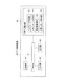
- FIG. 1 It is a figure showing an outline of a robot information processing system concerning an embodiment of the present invention. It is a block diagram which shows the structural example of the data processor which concerns on this embodiment. It is a figure which shows an example of accumulation
- FIG. 1 is a block diagram showing an outline of a robot information processing system according to an embodiment of the present invention.
- the robot information processing system 10 includes a robot body 20, a controller 30 that controls the operation of the robot body 20, and a data processing device 40, as shown in FIG.
- the robot body 20 and the controller 30 are configured as an industrial robot 50 that transports, for example, a semiconductor wafer or a glass substrate for a liquid crystal display panel (hereinafter referred to as a semiconductor wafer).
- the controller 30 controls the operation of the robot body 20, and the command data (position and speed) as input data in the normal production of the robot body 20 and servo data (torque, deviation, etc.) as output data are data processing devices. 40 is output in time series. That is, the command data and servo data are a large amount of data generated in time series.
- command data (position and speed) as input data is data created by a program or the like, and is not affected by aging.
- servo data (torque, deviation, etc.) as output data is data that is susceptible to secular changes such as a mechanical part that is a mechanical part constituting an industrial robot.
- the controller 30 of this embodiment uses a servo motor as a drive source of the robot arm 20ARM of the industrial robot 50, outputs command data from the controller 30 to the servo motor, and is attached to the servo motor.
- the detected value as servo data output from the encoder is fed back, and the rotational position of the servo motor and the like are made to coincide with the target value (command data) to follow the change of the target value (command data).
- the robot body 20 includes a robot base 21, an arm base portion 22, a first arm portion 23, a second arm portion 24, and a hand 25, for example.
- an arm base shaft portion 22 extending in the Z-axis direction (vertical direction in the figure) of the orthogonal coordinate system set in the figure is arranged on the robot base 21 so as to be movable up and down.
- the hand 25 is configured such that a transport object such as a semiconductor wafer is placed thereon.
- the hand 25 is formed so as to releasably hold a conveyance object such as a semiconductor wafer placed thereon.
- the second arm portion 24 is fixedly attached to a second arm rotation shaft 26 rotatably provided at the distal end portion of the first arm portion 23 at the base end portion.
- the hand 25 is fixedly attached to a hand shaft 27 rotatably disposed at the distal end portion of the second arm portion 24 at the base end portion.
- the robot arm 20ARM of the robot body 20 includes the arm base shaft portion 22, the first arm portion 23, the second arm portion 24, the hand 25, the second arm rotating shaft 26, and the hand shaft 27.
- This type of robot arm 20ARM is called a SCARA horizontal articulated arm.
- a controller 30 as a robot controller, the hand 25 is moved to the X, Y, and Z axes. It is possible to move to a desired position in the direction.
- the robot body 20 includes a first arm driving unit 201 that rotationally drives the first arm unit 23, a second arm driving unit 202 that rotationally drives the second arm unit 24, a hand axis driving unit 203 that rotationally drives the hand shaft 27, Also, there is an elevating drive unit 204 that elevates and lowers the arm base shaft part 22 in the Z-axis direction.
- the first arm drive unit 201 is disposed in the internal space of the robot base 21 and includes a servo motor incorporating an encoder and a power transmission mechanism thereof.
- the second arm drive unit 202 is disposed in the internal space of the first arm unit 23 and includes a servo motor incorporating an encoder and a power transmission mechanism thereof.
- the hand shaft drive unit 203 is disposed in the internal space of the second arm unit 24 and includes a servo motor incorporating an encoder and a power transmission mechanism thereof.
- the power transmission mechanism includes, for example, a speed reducer, the power of the servo motor is transmitted to the input side of the speed reducer, the torque is amplified by a predetermined amplification ratio, and the rotational speed is decelerated by a predetermined speed reduction ratio, Output from the output side of the reducer.
- a speed reducer the power of the servo motor is transmitted to the input side of the speed reducer, the torque is amplified by a predetermined amplification ratio, and the rotational speed is decelerated by a predetermined speed reduction ratio, Output from the output side of the reducer.
- each of the arm base shaft portion 22, the second arm rotation shaft 26, and the hand shaft 27 is rotationally driven by the power output from the output side of the reduction gear.
- each of the 1st arm part 23, the 2nd arm part 24, and the hand 25 is rotationally driven.
- the elevating drive unit 204 is disposed inside the robot base 21 and is realized by a ball screw mechanism using a motor capable of adjusting the amount of angular displacement.
- the lift drive unit 204 includes a ball screw, a screwed body that is screwed to the ball screw, and a motor that rotationally drives the ball screw, and the arm base shaft part 22 is fixed to the screwed body.
- a servo motor incorporating an encoder is used as the motor of the lift drive unit 204.
- the arm base shaft portion 22 is rotationally driven around the rotation axis RX1 with respect to the robot base 21 by the first arm driving portion 201.
- the first arm unit 23 is rotationally driven around the rotation axis RX ⁇ b> 1 with respect to the robot base 21.
- the second arm rotation shaft 26 is rotationally driven around the rotation axis RX2 with respect to the first arm portion 23 by the second arm driving unit 202. Accordingly, the second arm portion 24 is rotationally driven around the rotation axis RX ⁇ b> 2 with respect to the first arm portion 23.
- the hand shaft 27 is rotationally driven around the rotation axis RX3 with respect to the second arm unit 24 by the hand shaft driving unit 203.
- the hand 25 is rotationally driven around the rotation axis RX3 with respect to the second arm portion 24.
- the servo motors of the first arm driving unit 201, the second arm driving unit 202, the hand axis driving unit 203, and the lifting / lowering driving unit 204 are basically input by the controller 30 in normal production operations. And servo data such as torque and deviation is output to the controller 30 in time series.
- the controller 30 outputs a position or speed command to the first arm driving unit 201, the second arm driving unit 202, the hand axis driving unit 203, and the lifting / lowering driving unit 204 to be controlled, and the servo motor of each driving unit is output.
- Each drive unit is feedback-controlled by obtaining the angular position of each servo motor from the encoder. Thereby, the hand 25 can be accurately aligned with the target position.
- the controller 30 is generated in time series of commands (position or speed) and servo data (torque, deviation, etc.) that are information related to drive control of the servo system drive source (servo motor) of the robot body 20 in normal production operation.
- a large amount of data S30 is output to the data processing device 40.
- the position data (or velocity data) as the command data is input data that is input to control the operation of the industrial robot 50, and is data that is output from the controller 30 to the corresponding drive unit of the robot body 20. It is.
- the servo data is output data output from the industrial robot 50 that controls the operation based on the command data, and is data output from the drive unit of the robot body 20 to the controller 30.
- the controller 30 can output position data (or speed data) as command data and servo data (torque, deviation, etc.) as output data to the CPC 40 as a data processing device in accordance with the normal production operation of the robot body 20. It is configured as follows. In the present embodiment, the position data (or speed data) and servo data (torque, deviation, etc.) are output from the controller 30 in time series.
- the controller 30 includes, for example, a CPU (Central Processing Unit) 31 and a memory 32.
- the CPU 31 controls the robot body 20 by executing an operation program stored in the memory 32.
- Data (position data) relating to teaching points for controlling the operation of the robot body 20 can be stored in the memory 32.
- the hand 25 can move to a predetermined position. It is moved to.
- the memory 32 also stores data related to the shape and dimensions of the hand 25 and data related to the shape and dimensions of the semiconductor wafer and the like held by the hand 25.
- the data processing apparatus 40 includes position data (or speed data) and servo data, which are information related to drive control of the servo drive source, output from the controller 30 in accordance with the normal production operation of the robot body 20. (Torque, deviation, etc.) is collected and subjected to predetermined processing. For example, from a large amount of data generated in time series, the preconditions such as operating conditions, environmental conditions, and operating patterns are to be compared with the reference data. It has a function to extract easily and accurately.
- the data processing apparatus 40 basically performs a predetermined process on a large amount of data generated in time series input from the controller 30, and obtains position data (or speed data) and servo data.
- the pattern extraction unit of the data processing device 40 is a template of an operation pattern as reference data based on command data as input data, that is, position data (or velocity data), among a large amount of data generated in time series.
- the similarity determination function of the pattern extraction unit determines the similarity based on the correlation value between the template and the comparison pattern, for example. In this way, by calculating the similarity using the correlation value, the formula is not a high-order and complicated formula, so the processing time may be short and the computer need not be high in processing capacity, and it is versatile. Are better.
- a large amount of data generated in time series includes command data that is input to control the operation of the industrial robot body 20, and output data from the industrial robot body 20 that operates based on the command.
- the template and the comparison pattern are created from the command data.
- the pattern extraction unit compares corresponding data of the template and the comparison pattern.
- the corresponding servo data is associated with each of the template and the comparison pattern, and the pattern extraction unit compares the corresponding servo data of the template and the comparison pattern. That is, in the present embodiment, the influence of secular change can be quantified by comparing the servo data corresponding to the template and the comparison pattern.
- the servo data includes, for example, torque data, and the pattern extraction unit compares the torque data corresponding to the template and the comparison pattern.
- FIG. 2 is a block diagram showing a configuration example of the data processing apparatus according to the present embodiment.
- the data processing device 40 of FIG. 2 is configured by a personal computer (PC) or the like, and includes a control unit 41, an input unit 42, an output unit 43, a storage unit 44, and a pattern extraction unit 45.
- PC personal computer
- the control unit 41 includes various memories such as a CPU, ROM, RAM, and an external storage device, and performs control of each unit, temporary storage control of data, transfer control of data, and the like.
- the input unit 42 receives information input by the user using a keyboard, a mouse, or the like, and supplies the received information to the control unit 41. Data output from the robot body 20 is also received here by the control unit 41 and sent to the storage unit 44.
- the output unit 43 performs display on a display such as a CRT (Cathode Ray Tube) or LCD (Liquid Crystal Display device), or performs printing by a printer.
- a display such as a CRT (Cathode Ray Tube) or LCD (Liquid Crystal Display device)
- the storage unit 44 receives various setting data (programs, etc.), input data (position and speed command) supplied to the industrial robot body 20 as a large amount of data generated in time series, and outputs from the industrial robot body 20.
- Servo data torque data, deviation data, etc.
- comparison result data are stored.
- the pattern extraction unit 45 creates a template from input data (position command, speed command) supplied to the industrial robot body 20, and preconditions such as operation conditions, environmental conditions, and operation patterns are templates (reference data). Substantially the same operation pattern (comparison pattern) is extracted.
- the pattern extraction unit 45 includes a template creation unit 451, a comparison (operation) pattern creation unit 452, a similarity acquisition unit 453, and a comparison pattern extraction unit (comparison unit) 454.
- the template creation unit 451 creates a reference operation pattern template from a large amount of data generated in time series accumulated in the storage unit 44.
- the comparison pattern creation unit 452 creates a comparison pattern (operation pattern) as a target to be compared with the created template from a large amount of data generated in time series.
- the similarity acquisition unit 453 acquires the similarity between the comparison pattern selected from the large amount of data generated in time series and the template.
- the template and the comparison pattern (operation pattern) are data that is generated by a program or the like as a command (position or speed) as input data, and is not affected by aging. is there. Therefore, it is considered that the template and the comparison pattern (operation pattern) substantially match the preconditions such as the operation condition, the environmental condition, and the operation pattern.
- the comparison pattern extraction unit 454 extracts a comparison pattern that becomes a similar operation pattern to the template based on the similarity acquired by the similarity acquisition unit 453, and stores it in the storage unit 44, for example, under the control of the control unit 41. .
- FIG. 3 is a diagram illustrating an example of accumulation in a storage unit of acquired data from the controller in the data processing apparatus according to the present embodiment.
- FIG. 4 is a diagram illustrating an example of creating an operation template.
- the data processing device 40 accumulates the position command and torque data acquired from the controller 30 in the storage unit 44 in the form shown in FIG. FIG. 3 clearly shows the time at which data was collected, the position command pulse as input data at each time, and the output torque as output data corresponding to the position command pulse.
- the position command pulse is indicated by the number of outputs (number of pulses) of an encoder attached to each motor.
- the torque data is a current equivalent value and is an internal control value proportional to the current value supplied to the motor. In the example of FIG. 3, a part of the position command and torque data acquired in units of about 20 msec are extracted.
- Hand, Z, TH Corresponds to the name of the operation axis of the robot.
- the operation axis Hand corresponds to the hand axis 27 in FIG. 1
- the operation axis Z corresponds to the arm base axis of the arm base shaft portion 22 driven up and down in the Z-axis direction.
- the operation axis TH corresponds to, for example, the second arm rotation axis 26 in FIG.
- the pattern extraction unit 45 of the data processing device 40 is configured to store the continuous data of the axis position command (or speed command) for which it is desired to check (check) the servo data change from the past accumulated in the storage unit 44 in the template creation unit 451.
- the cluster is selected as a template TMP as shown in FIG. 4, for example.
- the template TMP can be operated normally when the trial operation is completed when the industrial robot 50 is put into production for the first time or when the power transmission mechanism of the industrial robot is repaired or replaced. It is created from the data even when it becomes. In other words, the reference data is acquired when the power transmission mechanism or the like has not deteriorated over time.
- the reference data can be acquired at any point in time if the deterioration over time has not progressed, so the reference data acquisition stage does not need to be strictly determined.
- the horizontal axis represents time
- the vertical axis represents the movement distance of the hand 25 as a relative value.
- FIG. 4 is merely an example, and a block of data is registered as an operation template TMP in succession with the position command pulse of the Hand axis in FIG. 3 and is displayed in a graph for easy understanding.
- FIG. 5 is a diagram illustrating an operation example of the hand of the robot body when creating a template in the data processing apparatus according to the present embodiment.
- FIG. 6 is a diagram in which a hand in the robot body is associated with a stocker that stores a semiconductor wafer or the like (conveyance target).
- FIG. 7 is a diagram specifically illustrating the operation of the hand corresponding to FIG. 5 using a hand and a stocker. 6 and 7, reference numeral 60 denotes a stocker for storing a semiconductor wafer or the like (conveyance object), and reference numeral 70 denotes a semiconductor wafer or the like as an example of the conveyance object.
- reference numeral 61 denotes one shelf having a plurality of mounting shelves formed in the stocker 60.
- FIG. 7 shows an operation in which the robot unloads a semiconductor wafer or the like from the stocker. This includes the movement of the hand in the Z-axis direction, from bottom to top in the figure.
- steps ST1 to ST4 correspond to the symbols ST1 to ST4 attached to the template graph of FIG.
- the hand 25 at the first position PT1 starts to extend in the direction of the stocker 60, and as shown in FIG. 7A, the second position PT2 at which the semiconductor wafer 70 to be transported can be held. Move horizontally.
- This state is step ST2.
- the lower surface portion of the semiconductor wafer 70 and the like is held by the hand 25 at the second position PT2 by a method such as suction, and as shown in FIG.
- the arm base shaft portion 22 starts to rise (vertical movement) in the Z-axis direction.
- the ascent is completed at the third position PT3 in the Z-axis direction.
- the hand 25 is horizontally moved away from the stocker 60 and returned to the fourth position PT4 to complete a series of operations.
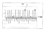
- FIG. 8 is a diagram for explaining a comparison pattern search method when a correlation value is used as the similarity of the data processing apparatus according to the present embodiment.
- the correlation value between the position command pulse of the operation template and the position command pulse in the target data range is taken.
- FIG. 8 is a graph showing the correlation values as an example of the cutting method. Among these, those having a correlation value of 0.999 or more are extracted as much as possible (circled portion indicated by symbol A in FIG. 8). The reason why the correlation value is 0.999 or more is extracted as shown in FIG. 6 because the relationship between the industrial robot 50 and the hand 25 and the mounting shelf 61 formed in the stocker 60 is Each shelf is different. Although not shown, since the stocker 60 is provided with a plurality of stockers, the positional relationship between the industrial robot 50 and each stocker is also different. Such a difference is caused as a difference in correlation values as shown in FIG.
- FIG. 9 is a graph showing the operation of the circled portion in FIG. If the comparison pattern of FIG. 9 is compared with the operation template of FIG. 4, they can be regarded as substantially the same operation (substantially the same operation) or similar operations.
- corresponding data (torque data as servo data in this embodiment) is associated with the template and the operation pattern described above.
- servo data is compared on the assumption that the same input condition (template and operation pattern) is the same.
- the input condition is the same because the template and the operation pattern in the position command are the same.
- the aging of the robot causes, for example, the life and deterioration of motors, bearings, etc., but by comparing the output of the robot body (servo data) against the same input conditions (position command) By examining the output difference, it becomes possible to determine the life of each part, the replacement time, and the like.
- FIG. 10 is a flowchart for explaining the overall operation of the robot information processing system according to the present embodiment. Next, the overall operation of the robot information processing system having the above configuration will be described with reference to the flowchart of FIG.
- the controller 30 outputs a command and servo data, which are information related to drive control of the servo system drive source, to the data processing device 40 as data S30 (step ST12).
- the data processor 40 collects the input command and servo data in units of about 20 msec, for example, and accumulates the collected data in the storage unit 44 (steps ST13 and ST14).
- the target industrial robot has a positional relationship facing the stocker 60 that accommodates the semiconductor wafer, and the robot hand 25 carries the semiconductor wafer into the stocker 60. Or carry out from the stocker.
- the robot processes the operations shown in FIG. 7 for each stage in the stocker shown in FIG. 6, but the robot hand may vary depending on the position of one or a plurality of stockers and the positional relationship of each stocker with the robot. The position of is slightly different. Specifically, the values on the vertical axis of the operation pattern shown in FIG.
- an operation pattern that is substantially the same as a slightly different operation pattern (a correlation value of 0.999 in the embodiment) is selected from a large amount (a huge amount) of data generated in time series. ) Is accurately and easily processed in a short time.
- the data processing device 40 creates a template that is a reference or reference operation pattern from a large amount of data generated in time series (step ST15).
- the data processing device 40 acquires a similarity (for example, a correlation value) and extracts a comparison pattern that is substantially the same operation pattern as the created template from the large amount of data described above (step ST16). That is, it is determined whether or not the template and the selected comparison pattern substantially match (step ST17). If they match (Yes in step ST17), the matching comparison pattern is extracted (step ST18) and stored. The data is stored in the unit 44 (step ST19). If it is determined in step ST17 that the template does not substantially match the selected comparison pattern (No in step ST17), the process returns to step ST16. Note that the creation of a template and an operation pattern (comparison pattern) is repeatedly executed.
- step ST20 the servo data between the extracted comparison pattern and the operation pattern as a template is compared (step ST20), and the secular change is confirmed (step ST21).
- the robot information processing system 10 including the data processing apparatus of this embodiment has the following configuration.
- the controller 30 can always output position data (or speed data) and servo data (torque, deviation, etc.), and the data processor 40 collects, stores, and accumulates a large amount of data generated in time series.
- the data processing apparatus 40 uses a position command (or speed command) as a template (reference data) for a desired operation pattern, for example, an operation pattern in which aging has been confirmed.
- the data processing apparatus 40 acquires the similarity with the past accumulated position command (or speed command) in the template, and extracts a matching (highly similar) operation pattern. Then, although it is optional, the servo data between the operation pattern templates with the extracted operation pattern is compared to confirm (check) the secular change.
- the production operation in the case of an industrial robot is basically a repetitive operation, so the same operation is always performed over time.
- the operations shown in FIGS. 5 and 7 are performed for each shelf of the plurality of placement shelves 61 of the stocker 60 and for the plurality of stockers. 5 and 7, the operation is to carry out the semiconductor wafer 70 and the like stored in the stocker 60.
- the hand 25 is used to remove the semiconductor wafer 70 and the like from the mounting shelf 61 of the stocker 60. There is an operation to carry in to the shelf.
- the velocity pattern template can be extracted as a single motion, the position pattern template can be extracted as a combined motion, and if multiple templates for each axis are used, long motion patterns can be compared with each other. Comparison with is possible.
- the operation of the industrial robot 50 is the operation shown in FIGS. 5 and 7, position data as a position command is adopted as the template and the pattern as the operation pattern. That is, it is a simple trapezoidal shape as shown in FIGS.
- the operation of the industrial robot 50 is complicated, it may be a complicated shape instead of a simple trapezoidal shape when represented by a position pattern. In such a case, only one operation, that is, the operation of step ST1 in FIG. 5 (FIG.
- step ST1 may be used to use the speed data as the speed command.
- the speed is increased by accelerating from the stopped state until reaching a predetermined operation, and then the speed is decreased to a certain speed and further to stop the operation. As a result, the speed becomes zero and the vehicle stops at a predetermined position. If this operation is graphed by the relationship between speed, position, and time, it can be expressed by a simple trapezoidal shape similar to FIGS.
- the operation pattern when an error occurs can also be used as a template to extract the same operation pattern from the past and compare changes in servo data.
- the cause of the error is related to the servo system. You can decide whether to do it.
- this data processing apparatus it is possible to check whether the servo data has changed from the same past operation using the operation pattern at the time of error as a template. As a result, it can be determined whether the error factor is caused by the servo system including the mechanism unit. For example, an operation pattern in which an error has occurred is templated from position (or velocity) data accumulated up to that point when a servo system error has occurred. The same operation pattern is extracted from the template in the past. Compare the past servo data of the same operation pattern with the servo data of the operation pattern in which an error occurred to check whether the cause of the error is due to the servo.
- the cycle time can be automatically derived. Register the cycle time operation pattern as a template. The past operation pattern is searched, the same operation pattern is extracted, and the cycle time is calculated.
- the data processing device 40 that collects and processes a large amount of data generated in time series includes the storage unit 44 that stores a large amount of input data. And a pattern extraction unit 45 for extracting a reference operation pattern template and a comparison pattern similar to the template from the data stored in the storage unit 44. Then, the pattern extraction unit 44 obtains the similarity between the template creation unit 451 that creates a template from the stored data, the comparison pattern selected from the stored data, and the template. A comparison pattern extraction unit 454 that extracts and stores a comparison pattern that becomes a similar operation pattern with the template based on the similarity acquired by the similarity acquisition unit 453.
- the data processing apparatus of the present embodiment it is possible to easily and accurately extract data to be compared from a large amount of data generated in time series.
- the similarity determination unit 453 of the pattern extraction unit 45 is configured to determine the similarity based on the correlation value between the template and the comparison pattern.
- the processing time may be short because the expression is not a high-order and complicated expression by obtaining the similarity using the correlation value. It does not have to be a computer with high processing capability, and it has the advantage of excellent versatility.
- the data generated in time series includes a command input for controlling the operation of the industrial robot 50 and an output from the industrial robot 50 that operates based on the command.
- the template and the comparison pattern are created from the command data.
- the pattern extraction part 45 is comprised so that the data corresponding to a template and a comparison pattern may be compared.
- the servo data includes torque data, and the pattern extraction unit 45 compares the torque data corresponding to the template and the comparison pattern.
- the data processing device 40 of the present embodiment there is a problem that it is difficult to set the same input condition in the existing technology.
- the same input condition template and There is an advantage in comparing the servo data on the assumption that the operation pattern is the same.
- the data processing device 40 having this configuration the following effects can be obtained. (1) It is not necessary to prepare an operation different from a normal production operation, such as a basic data acquisition operation, in order to see an aging change of a servo relation as in the existing technology. (2) Since the torque data of the production operation itself is inspected, analysis based on actual data is possible. (3) The following can be performed by the template function of this arbitrary specific operation.
- past data can be searched using the operation pattern at that time as a template, and compared with normal torque data, and it can be determined whether the servo system is the cause.
- the past operation pattern is extracted using the operation pattern at that time as a template, compared with past torque data, and there is no change in the mechanical system Can be judged.
- the method described in detail above can be formed as a program corresponding to the above procedure and executed by a computer such as a CPU.
- the operation at the time when aging has not progressed is selected as the template.
- the present invention is not limited to this.
- a cluster of continuous data of axis position commands (or speed commands) for which the template creation unit 451 wants to check (check) the servo data change from the past accumulated in the storage unit 44. May be used as a template.
- Such a program can be configured to be accessed by a recording medium such as a semiconductor memory, a magnetic disk, an optical disk, a floppy (registered trademark) disk, or the like, and to execute the program by a computer in which the recording medium is set.
- a recording medium such as a semiconductor memory, a magnetic disk, an optical disk, a floppy (registered trademark) disk, or the like.
Landscapes
- Engineering & Computer Science (AREA)
- Robotics (AREA)
- Mechanical Engineering (AREA)
- Physics & Mathematics (AREA)
- General Physics & Mathematics (AREA)
- Automation & Control Theory (AREA)
- Manipulator (AREA)
- General Factory Administration (AREA)
- Testing And Monitoring For Control Systems (AREA)
- Numerical Control (AREA)
Abstract
La présente invention porte sur un dispositif de traitement de données et un procédé de traitement de données au moyen desquels il est possible d'extraire facilement et très précisément des données pour comparaison à partir d'une grande quantité de données qui surviennent en série chronologique. A titre d'exemple, un dispositif de traitement de données (40) comprend : une unité de stockage (44) qui stocke une grande quantité de données entrées qui surviennent en série chronologique ; et une unité d'extraction de motif (45) qui extrait respectivement un modèle d'un motif d'opération qui est une référence, et un motif de comparaison qui est similaire au modèle, à partir des données accumulées dans l'unité de stockage (44). L'unité d'extraction de motif (45) comprend en outre : une unité de création de modèle (451) qui crée le modèle à partir des données stockées dans l'unité de stockage ; une unité d'acquisition de similarité (453) qui acquiert une similarité entre le motif de comparaison qui est sélectionné à partir des données stockées dans l'unité de stockage et le modèle ; et une unité d'extraction de motif de comparaison (454) qui extrait et stocke un motif de comparaison qui est un motif d'opération similaire au modèle, sur la base de la similarité qui est acquise par l'unité d'acquisition de similarité.
Priority Applications (1)
| Application Number | Priority Date | Filing Date | Title |
|---|---|---|---|
| CN201480030655.1A CN105247430B (zh) | 2013-05-29 | 2014-05-13 | 数据处理装置及数据处理方法 |
Applications Claiming Priority (2)
| Application Number | Priority Date | Filing Date | Title |
|---|---|---|---|
| JP2013113363A JP6211802B2 (ja) | 2013-05-29 | 2013-05-29 | データ処理装置およびデータ処理方法 |
| JP2013-113363 | 2013-05-29 |
Publications (1)
| Publication Number | Publication Date |
|---|---|
| WO2014192525A1 true WO2014192525A1 (fr) | 2014-12-04 |
Family
ID=51988563
Family Applications (1)
| Application Number | Title | Priority Date | Filing Date |
|---|---|---|---|
| PCT/JP2014/062647 Ceased WO2014192525A1 (fr) | 2013-05-29 | 2014-05-13 | Dispositif de traitement de données et procédé de traitement de données |
Country Status (3)
| Country | Link |
|---|---|
| JP (1) | JP6211802B2 (fr) |
| CN (1) | CN105247430B (fr) |
| WO (1) | WO2014192525A1 (fr) |
Families Citing this family (8)
| Publication number | Priority date | Publication date | Assignee | Title |
|---|---|---|---|---|
| JP6563210B2 (ja) * | 2015-02-17 | 2019-08-21 | 日本電産サンキョー株式会社 | 動作履歴管理システム、管理装置、及び動作履歴管理方法 |
| JP2016179527A (ja) | 2015-03-24 | 2016-10-13 | ファナック株式会社 | ロボットの異常診断を行う機能を有するロボット制御装置 |
| JP7192251B2 (ja) * | 2018-05-29 | 2022-12-20 | 富士通株式会社 | 情報処理装置、ロボット動作プログラム生成補助方法及びロボット動作プログラム生成補助プログラム |
| CN110308669B (zh) * | 2019-07-27 | 2021-07-30 | 南京市晨枭软件技术有限公司 | 一种模块机器人自修复仿真系统及方法 |
| JP2021135780A (ja) * | 2020-02-27 | 2021-09-13 | 株式会社東芝 | 状態監視装置、方法及びプログラム |
| CN113971230B (zh) * | 2020-07-24 | 2024-12-20 | 北京达佳互联信息技术有限公司 | 动作搜索方法、装置、电子设备及存储介质 |
| CN113211426B (zh) * | 2020-12-02 | 2023-02-28 | 格创东智(深圳)科技有限公司 | 机器人故障诊断方法、装置、计算机设备以及存储介质 |
| JP7746237B2 (ja) * | 2022-08-25 | 2025-09-30 | 株式会社栗本鐵工所 | 測定波形表示装置およびプログラム |
Citations (6)
| Publication number | Priority date | Publication date | Assignee | Title |
|---|---|---|---|---|
| JPH07160323A (ja) * | 1993-12-02 | 1995-06-23 | Nissan Motor Co Ltd | 産業用ロボットの動作波形診断装置 |
| JP2002268728A (ja) * | 2001-03-08 | 2002-09-20 | Yamatake Sangyo Systems Co Ltd | 同期診断監視システム、同期診断監視装置、および同期診断監視プログラム |
| JP2002287816A (ja) * | 2001-03-27 | 2002-10-04 | Yaskawa Electric Corp | 遠隔調整及び診断装置 |
| JP2003058248A (ja) * | 2001-08-10 | 2003-02-28 | Mitsubishi Electric Corp | 運転支援装置 |
| JP2007172150A (ja) * | 2005-12-20 | 2007-07-05 | Honda Motor Co Ltd | 産業機械の故障診断方法 |
| JP2009169556A (ja) * | 2008-01-12 | 2009-07-30 | Kanto Auto Works Ltd | トレーシングシステム |
Family Cites Families (9)
| Publication number | Priority date | Publication date | Assignee | Title |
|---|---|---|---|---|
| JPS57207908A (en) * | 1981-06-17 | 1982-12-20 | Hitachi Ltd | Robot controller |
| JP4849804B2 (ja) * | 2004-09-28 | 2012-01-11 | 日本電産サンキョー株式会社 | ロボットの作動方法 |
| JP4374039B2 (ja) * | 2007-06-14 | 2009-12-02 | ファナック株式会社 | スポット溶接システム及び溶接ガン閉速度調整方法 |
| US8892497B2 (en) * | 2010-05-17 | 2014-11-18 | Panasonic Intellectual Property Corporation Of America | Audio classification by comparison of feature sections and integrated features to known references |
| CN103003803B (zh) * | 2010-08-11 | 2016-08-03 | 株式会社日立制作所 | 时序数据处理装置及其方法 |
| JP5743495B2 (ja) * | 2010-11-05 | 2015-07-01 | キヤノン株式会社 | ロボット制御装置 |
| JP2012232370A (ja) * | 2011-04-28 | 2012-11-29 | Seiko Epson Corp | ロボットコントローラー、簡易設置型ロボット、及び簡易設置型ロボットの制御方法 |
| JP5284433B2 (ja) * | 2011-09-14 | 2013-09-11 | 株式会社東芝 | プロセス監視・診断・支援装置 |
| CN103049459A (zh) * | 2011-10-17 | 2013-04-17 | 天津市亚安科技股份有限公司 | 一种基于特征识别的快速录像检索方法 |
-
2013
- 2013-05-29 JP JP2013113363A patent/JP6211802B2/ja active Active
-
2014
- 2014-05-13 WO PCT/JP2014/062647 patent/WO2014192525A1/fr not_active Ceased
- 2014-05-13 CN CN201480030655.1A patent/CN105247430B/zh active Active
Patent Citations (6)
| Publication number | Priority date | Publication date | Assignee | Title |
|---|---|---|---|---|
| JPH07160323A (ja) * | 1993-12-02 | 1995-06-23 | Nissan Motor Co Ltd | 産業用ロボットの動作波形診断装置 |
| JP2002268728A (ja) * | 2001-03-08 | 2002-09-20 | Yamatake Sangyo Systems Co Ltd | 同期診断監視システム、同期診断監視装置、および同期診断監視プログラム |
| JP2002287816A (ja) * | 2001-03-27 | 2002-10-04 | Yaskawa Electric Corp | 遠隔調整及び診断装置 |
| JP2003058248A (ja) * | 2001-08-10 | 2003-02-28 | Mitsubishi Electric Corp | 運転支援装置 |
| JP2007172150A (ja) * | 2005-12-20 | 2007-07-05 | Honda Motor Co Ltd | 産業機械の故障診断方法 |
| JP2009169556A (ja) * | 2008-01-12 | 2009-07-30 | Kanto Auto Works Ltd | トレーシングシステム |
Also Published As
| Publication number | Publication date |
|---|---|
| CN105247430B (zh) | 2017-09-05 |
| CN105247430A (zh) | 2016-01-13 |
| JP6211802B2 (ja) | 2017-10-11 |
| JP2014232450A (ja) | 2014-12-11 |
Similar Documents
| Publication | Publication Date | Title |
|---|---|---|
| JP6211802B2 (ja) | データ処理装置およびデータ処理方法 | |
| US12508711B2 (en) | Robot system and a method for monitoring a robot system | |
| JP5399624B2 (ja) | 数値制御方法及び数値制御装置 | |
| JP5235376B2 (ja) | ロボットのターゲット位置検出装置 | |
| US9471058B2 (en) | Data acquisition device for acquiring cause of stoppage of drive axis and information relating thereto | |
| JP5249452B1 (ja) | 補正データを考慮した軌跡表示装置 | |
| US20190361467A1 (en) | Control parameter adjustment apparatus | |
| EP2308657B1 (fr) | Robot et son procédé d'apprentissage | |
| JP5529920B2 (ja) | ロボットのターゲット位置検出装置、半導体装置およびターゲット位置検出方法 | |
| JP2018069381A (ja) | 把持装置の制御方法、把持装置、ロボット装置、および部品の製造方法 | |
| JP2022084259A (ja) | 情報処理装置、情報処理方法、ロボットシステム、測定システム、ロボットシステムを用いた物品の製造方法、制御プログラム及び記録媒体 | |
| JP2015085491A (ja) | ロボット制御装置、ロボット及びロボット制御方法 | |
| JP7103136B2 (ja) | 工作機械及び加工方法 | |
| CN116423389B (zh) | 一种用于机器人光学元件抛光的工件坐标系确定方法 | |
| CN206216693U (zh) | 一种针对解决形变问题的机器人磨削系统 | |
| US20250100154A1 (en) | Computer-implemented method for controlling a robot, robot control method, system, article manufacturing method, and recording medium | |
| CN114952623A (zh) | 用于主动控制打磨力的数控机床打磨操作的控制方法 | |
| JP5401748B2 (ja) | ロボット及びその教示方法 | |
| Subačiūtė-Žemaitienė et al. | Experimental evaluation of microrobot positioning accuracy | |
| CN121548486A (zh) | 控制装置、参数校正方法以及程序 | |
| JP2015222196A (ja) | 三次元測定機、及びこれを用いた形状測定方法 | |
| CN114290330A (zh) | 机器人的校准方法和校准装置、机器人和可读存储介质 | |
| JP5620463B2 (ja) | ロボットのターゲット位置検出装置 | |
| JPH0580828A (ja) | 三次元レーザ加工機のオフライン教示方法 | |
| JPH0430941A (ja) | 工作機械の熱変形補正方法 |
Legal Events
| Date | Code | Title | Description |
|---|---|---|---|
| 121 | Ep: the epo has been informed by wipo that ep was designated in this application |
Ref document number: 14803357 Country of ref document: EP Kind code of ref document: A1 |
|
| NENP | Non-entry into the national phase |
Ref country code: DE |
|
| 122 | Ep: pct application non-entry in european phase |
Ref document number: 14803357 Country of ref document: EP Kind code of ref document: A1 |