WO2014199950A1 - 電力制御装置、及び電力制御装置の制御方法 - Google Patents
電力制御装置、及び電力制御装置の制御方法 Download PDFInfo
- Publication number
- WO2014199950A1 WO2014199950A1 PCT/JP2014/065226 JP2014065226W WO2014199950A1 WO 2014199950 A1 WO2014199950 A1 WO 2014199950A1 JP 2014065226 W JP2014065226 W JP 2014065226W WO 2014199950 A1 WO2014199950 A1 WO 2014199950A1
- Authority
- WO
- WIPO (PCT)
- Prior art keywords
- current
- voltage
- electrolytic
- electrolytic cell
- circuit
- Prior art date
- Legal status (The legal status is an assumption and is not a legal conclusion. Google has not performed a legal analysis and makes no representation as to the accuracy of the status listed.)
- Ceased
Links
Images

Classifications
-
- C—CHEMISTRY; METALLURGY
- C02—TREATMENT OF WATER, WASTE WATER, SEWAGE, OR SLUDGE
- C02F—TREATMENT OF WATER, WASTE WATER, SEWAGE, OR SLUDGE
- C02F1/00—Treatment of water, waste water, or sewage
- C02F1/46—Treatment of water, waste water, or sewage by electrochemical methods
- C02F1/461—Treatment of water, waste water, or sewage by electrochemical methods by electrolysis
- C02F1/46104—Devices therefor; Their operating or servicing
-
- C—CHEMISTRY; METALLURGY
- C02—TREATMENT OF WATER, WASTE WATER, SEWAGE, OR SLUDGE
- C02F—TREATMENT OF WATER, WASTE WATER, SEWAGE, OR SLUDGE
- C02F1/00—Treatment of water, waste water, or sewage
- C02F1/008—Control or steering systems not provided for elsewhere in subclass C02F
-
- C—CHEMISTRY; METALLURGY
- C02—TREATMENT OF WATER, WASTE WATER, SEWAGE, OR SLUDGE
- C02F—TREATMENT OF WATER, WASTE WATER, SEWAGE, OR SLUDGE
- C02F2201/00—Apparatus for treatment of water, waste water or sewage
- C02F2201/46—Apparatus for electrochemical processes
- C02F2201/461—Electrolysis apparatus
- C02F2201/46105—Details relating to the electrolytic devices
- C02F2201/4612—Controlling or monitoring
- C02F2201/46125—Electrical variables
-
- C—CHEMISTRY; METALLURGY
- C02—TREATMENT OF WATER, WASTE WATER, SEWAGE, OR SLUDGE
- C02F—TREATMENT OF WATER, WASTE WATER, SEWAGE, OR SLUDGE
- C02F2201/00—Apparatus for treatment of water, waste water or sewage
- C02F2201/46—Apparatus for electrochemical processes
- C02F2201/461—Electrolysis apparatus
- C02F2201/46105—Details relating to the electrolytic devices
- C02F2201/4612—Controlling or monitoring
- C02F2201/46125—Electrical variables
- C02F2201/46135—Voltage
-
- C—CHEMISTRY; METALLURGY
- C02—TREATMENT OF WATER, WASTE WATER, SEWAGE, OR SLUDGE
- C02F—TREATMENT OF WATER, WASTE WATER, SEWAGE, OR SLUDGE
- C02F2201/00—Apparatus for treatment of water, waste water or sewage
- C02F2201/46—Apparatus for electrochemical processes
- C02F2201/461—Electrolysis apparatus
- C02F2201/46105—Details relating to the electrolytic devices
- C02F2201/4612—Controlling or monitoring
- C02F2201/46125—Electrical variables
- C02F2201/4614—Current
-
- C—CHEMISTRY; METALLURGY
- C02—TREATMENT OF WATER, WASTE WATER, SEWAGE, OR SLUDGE
- C02F—TREATMENT OF WATER, WASTE WATER, SEWAGE, OR SLUDGE
- C02F2201/00—Apparatus for treatment of water, waste water or sewage
- C02F2201/46—Apparatus for electrochemical processes
- C02F2201/461—Electrolysis apparatus
- C02F2201/46105—Details relating to the electrolytic devices
- C02F2201/4616—Power supply
- C02F2201/4617—DC only
-
- C—CHEMISTRY; METALLURGY
- C02—TREATMENT OF WATER, WASTE WATER, SEWAGE, OR SLUDGE
- C02F—TREATMENT OF WATER, WASTE WATER, SEWAGE, OR SLUDGE
- C02F2209/00—Controlling or monitoring parameters in water treatment
- C02F2209/01—Density
Definitions
- the present invention relates to a power control device that supplies electric power to an electrolytic cell for producing electrolyzed water used for sterilizing water by electrolyzing raw material water, and a control method for the power control device.
- electrolyzed water obtained by electrolyzing raw water containing chlorine ions with an electrolyzed water production apparatus has advantages such as low chlorine concentration, high sterilization effect, and high safety to humans. It is known to have unique properties. Therefore, in the food-related field, etc., electrolyzed water is widely used for sterilizing food or equipment for processing the food. In particular, in recent years, the awareness of hygiene management of food or food handlers has increased, and therefore, development of an electrolyzed water production apparatus that can be easily used and maintained for general household use and business use is expected. .
- a power control device is arranged between a DC power source and an electrolytic cell, and a desired current is supplied to the electrolytic cell by the power control device based on the DC power supplied by the DC power source.
- a configuration in which raw water is electrolyzed by an energized current can be considered.
- the following Patent Document 1 discloses a constant current that supplies a desired constant current to the electrolytic cell 1 based on the direct current power of the direct current power source 41 in order to electrolyze seawater circulated in the main body of the electrolytic cell 1.
- a control circuit 42 is disclosed (see paragraphs “0032” to “0033”, “0049” to “0051” of Patent Document 1, and FIG. 2).
- the present invention has been made in view of the above points, and provides a highly versatile power control apparatus that can be commonly used for electrolytic cells having different cell configurations, and a control method for the power control apparatus. With the goal.
- the first aspect of the present invention provides an input for an electrolytic cell for electrolyzing raw water by an electric current passed between an anode and a cathode to produce electrolyzed water.
- the power control device supplies an electrolysis voltage and an electrolysis current based on the direct current power.
- this power control device electrolyzes the electrolysis current while controlling the electrolysis current so that it does not exceed the current value of the reference current set in advance according to the rated current of the unit cells constituting the electrolytic cell.
- the electrolytic voltage is controlled so that the electrolytic voltage does not exceed the rated voltage of the unit cell constituting the electrolytic cell and the reference voltage set in advance according to the number.
- Is provided with a voltage / current control circuit for supplying the electrolyte to the electrolytic cell.
- the voltage / current control circuit switches between the constant current control mode and the constant voltage control mode according to the concentration of the electrolyte to be electrolyzed in the electrolytic cell.
- a current detection unit that is connected to the output terminal of the voltage / current control circuit and detects a voltage generated between both ends thereof, and a reference current
- a voltage dividing unit that detects the voltage of the output terminal and divides the detected voltage to generate a feedback voltage.
- the voltage / current control circuit includes a voltage / current detection circuit that calculates an electrolytic current flowing in the electrolytic cell from a voltage between both ends of the current detection unit and a resistance value of the current detection unit, and a reference generated by the electrolytic current and the current limiting unit.
- the electrolytic current is supplied from the output terminal to the electrolytic cell while controlling so that the electrolytic current does not exceed the reference current, and electrolysis is performed while controlling the feedback voltage not to exceed the reference voltage based on the voltage comparison result signal.
- a voltage control circuit for supplying a voltage to the electrolytic cell.
- the reference current is supplied to the current limiting unit in response to a pulse signal having an externally input duty ratio being controlled.
- a current limit switching circuit that causes the current limiter to generate a low-side reference current having a value lower than the reference current and greater than zero in response to the pulse signal being in the OFF state.
- the comparator circuit compares the electrolysis current with the low-side reference current flowing through the current limiting unit, and outputs a current comparison result signal indicating the comparison result.
- the voltage control circuit reduces the electrolysis current based on the current comparison result signal.
- the electrolytic current is supplied to the electrolytic cell from the output terminal while controlling so as not to fall below the side reference current.
- the voltage control circuit of the power control apparatus of the third aspect outputs the output voltage signal that has been pulse-width modulated so as to correspond to the on state and the off state of the pulse signal. Output from the terminal.
- analog data indicating a current value of the electrolytic current in the power control device of the second or third aspect, analog data indicating a voltage value of the electrolytic voltage, analog data indicating a voltage value of the electrolytic voltage, A voltage-current monitor circuit is further provided that outputs a current detection signal indicating that the current value has fallen below the reference current to the outside.
- the sixth aspect of the present invention further includes a temperature detection unit for detecting the temperature of the electrolytic cell in the power control device according to any one of the first to third aspects.
- the voltage / current control circuit stops supplying the electrolysis voltage and the electrolysis current when the temperature detected by the temperature detection unit is outside a preset rated temperature range.
- the voltage / current control circuit resumes supply of the electrolysis voltage and the electrolysis current when the temperature detected by the temperature detector returns to within the rated temperature range.
- the seventh aspect of the present invention is based on DC power input to an electrolytic cell for electrolyzing raw material water to produce electrolyzed water by an electric current passed between an anode and a cathode.
- a control method for a power control device that supplies an electrolytic voltage and an electrolytic current. This power control device control method supplies the electrolytic current to the electrolytic cell while controlling the electrolytic current so that it does not exceed the current value of the reference current set in advance according to the rated current of the unit cells constituting the electrolytic cell.
- Constant current control step and control the electrolytic voltage to the electrolytic cell while controlling so that the rated voltage of the unit cell constituting the electrolytic cell and the voltage value of the reference voltage set in advance according to the number are not exceeded
- the power control device of the present invention supplies current and voltage to the electrolytic cell based on a reference value preset according to the rated current, rated voltage, and number of unit cells constituting the electrolytic cell. Therefore, according to the present invention, it is possible to provide a highly versatile power control apparatus that can be commonly used for electrolytic cells having different cell configurations, and a control method for the power control apparatus.
- the electrolysis using the power control apparatus is performed by a constant current / constant voltage electrolysis method, which will be described in detail later.
- a constant current / constant voltage electrolysis method which will be described in detail later.
- the maximum electrolysis voltage (rated voltage) is preferably designed to be 2.0 V (1.5 to 2.5 V) per cell depending on the design of the electrolytic cell (cell configuration).
- the maximum electrolysis current (rated current) is preferably designed to be a current value (current density) per electrode area according to the catalytic ability of the electrode.
- the power control apparatus can perform constant current / constant voltage electrolysis regardless of the cell configuration of the electrolytic cell.
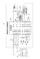
- FIG. 1 is a diagram showing a schematic configuration of an electrolytic cell constant voltage constant current power supply circuit 10 according to the present embodiment.
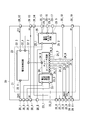
- FIG. 2 is a diagram showing a schematic configuration of the switching CVCC (Constant Voltage Constant Current) power supply circuit 20 (voltage / current control circuit) shown in FIG.
- the electrolytic cell constant voltage constant current power supply circuit 10 includes a switching CVCC power supply circuit 20, a current detection resistor 30 (current detection unit), a current limiting resistor 40 (current limiting unit), a voltage dividing resistor 50 (voltage dividing unit), and a current limit switching.
- the circuit 60 and the thermistor resistor 70 are included.
- the switching CVCC power supply circuit 20 has a load state (concentration of the electrolyzed solution in the electrolytic cell 1) within a predetermined reference voltage value / reference current value range, which will be described in detail later, within a range determined for each power supply. ) Automatically performs a constant voltage or constant current operation on the electrolytic cell 1. Therefore, the switching CVCC power supply circuit 20 includes each circuit shown in FIG. 1 and a first pin 20_1 to a 19th pin 20_19 as terminals for connection to the electrolytic cell 1.
- the switching CVCC power supply circuit 20 includes a voltage / current control circuit 21 and a voltage / current monitor circuit 25 as shown in FIG.
- the voltage / current control circuit 21 includes a voltage control circuit 22, a voltage / current detection circuit 23, and an amplifier / comparator circuit 24 (hereinafter simply referred to as a comparator circuit).
- the comparator circuit 24 has a function of amplifying the input signal.
- the first pin 20_1 is connected to the anode 1a of the electrolytic cell 1 through a current detection resistor 30.
- the first pin 20_1 is connected to the first pin 22_1 of the voltage control circuit 22 shown in FIG.
- the voltage control circuit 22 of the switching CVCC power supply circuit 20 is a circuit that supplies electric power (electrolytic voltage, electrolytic current) from the first pin 20_1 to the anode 1a of the electrolytic cell 1.
- the voltage control circuit 22 does not exceed the reference current value in the constant current mode (that is, by the constant current), and does not exceed the reference voltage value in the constant voltage mode (that is, by the constant voltage). ), Supplying electric power to the electrolytic cell 1.
- the second pin 20_2 is connected to one end of a current detection resistor 30 (the resistance value between both ends of the pin 20_2 is a resistance value Rs) and is connected to the voltage / current detection circuit 23 shown in FIG. Connected to the first pin 23_1.
- the third pin 20_3 is connected to the other end of the current detection resistor 30 and to the second pin 23_2 of the voltage / current detection circuit 23 shown in FIG.
- the voltage / current detection circuit 23 converts the voltage generated between both ends of the current detection resistor 30 (the voltage between both ends thereof) into the current value of the electrolytic current flowing through the electrolytic cell 1 (the voltage between both ends and the resistance value Rs). And the converted current value is output from the third pin 23_3 to the first pin 24_1 of the comparator circuit 24.
- the 4th pin 20_4 is connected to the cathode 1b of the electrolytic cell 1 as shown in FIG.
- the fourth pin 20_4 is a GND (ground) terminal and is grounded.
- the 13th pin 20_13 connected to the 4th pin 20_4 is a GND (ground) terminal and is connected to 0V, like the 4th pin 20_4.
- the fifth pin 20_5 is connected to the anode 1a of the electrolytic cell 1.
- the fifth pin 20_5 is connected to the first pin 25_1 of the voltage / current monitor circuit 25 shown in FIG.
- the voltage / current monitor circuit 25 outputs analog data indicating the voltage value of the voltage (electrolytic voltage) applied to the electrolytic cell 1 to the outside as one function.
- the current limiting resistor 40 includes a series resistance of a current limiting resistor 40a (referred to as a resistance value RP1) and a current limiting resistor 40b (referred to as a resistance value RP2).
- the 6th pin 20_6 is connected to one end of the current limiting resistor 40a.
- the 6th pin 20_6 is connected to the 2nd pin 24_2 of the comparator circuit 24.
- the seventh pin 20_7 is connected to a common connection point between the other end of the current limiting resistor 40a and one end of the current limiting resistor 40b.
- the 7th pin 20_7 is connected to the 1st pin 60_1 of the current limit switching circuit 60 via the 14th pin 20_14, as shown in FIGS.
- the eighth pin 20_8 is connected to the other end of the current limiting resistor 40b.
- the eighth pin 20_8 is connected to the third pin 24_3 of the comparator circuit 24.
- the current limiting resistor 40 is a resistor that determines the current flowing through the electrolytic cell 1.
- the relationship between the resistance (the resistance value Rprog) set between the 6th pin 20_6 and the 7th pin 20_7 and the electrolytic current Ielectrolytic is included in the comparator circuit 24.
- the resistance values RP1 and RP2 of the current limiting resistor 40 are the reference voltage used for comparison with the electrolysis current (hereinafter referred to as the current comparison reference voltage) and the current value that is desired to flow through the electrolytic cell 1 (each higher side).
- the current comparison reference voltage used for comparison with the electrolysis current
- the current value that is desired to flow through the electrolytic cell 1 each higher side.
- RP1 (reference voltage for current comparison ⁇ constant k) / (Rs ⁇ high-side reference current + internal offset voltage)
- RP1 + RP2 (reference voltage for current comparison ⁇ constant k / (Rs ⁇ low-side reference current + internal offset voltage)
- the high-side reference current is the upper limit value of the electrolysis current supplied to the electrolytic cell 1
- the low-side reference current is the lower limit value of the electrolysis current supplied to the electrolytic cell 1 (the current value is smaller than the high-side reference current, Current value greater than 0).
- Each of these reference currents is a current that flows between the second pin 24_2 and the third pin 24_3 of the comparator circuit 24.
- each reference current is controlled by the current limit switching circuit 60.
- the first pin 60_1 is connected to the current limiting resistor 40a via the 14th pin 20_14 and the 7th pin 20_7 of the switching CVCC power supply circuit 20. It is connected to a common connection point between the other end and one end of the current limiting resistor 40b.
- the second pin 60_2 is connected to 0V via the thirteenth pin 20_13 of the switching CVCC power supply circuit 20.
- An ON / OFF control signal (pulse signal with a controlled duty ratio) is input to the third pin 60_3 from the outside.
- the current limit switching circuit 60 controls the current limit resistor 40 to generate the above-described high-side reference current in accordance with the ON state of the ON / OFF control signal (the pulse signal is at the H level). Further, the current limit switching circuit 60 performs control for causing the current limit resistor 40 to generate the above-described low-side reference current according to the OFF state of the ON / OFF control signal (the pulse signal is in the L level).
- the voltage dividing resistor 50 includes a series resistance of a voltage dividing resistor 50a (with a resistance value R1) and a voltage dividing resistor 50b (with a resistance value R2).
- the ninth pin 20_9 is connected to one end of the voltage dividing resistor 50a.
- the ninth pin 20_9 is connected to, for example, the first pin 20_1, and an electrolytic voltage (monitor voltage Vmoni; detection voltage) applied to the electrolytic cell 1 is input.
- the ninth pin 20_9 is connected to the fourth pin 24_4 of the comparator circuit 24 shown in FIG.
- the tenth pin 20_10 is connected to a common connection point between the other end of the voltage dividing resistor 50a and one end of the voltage dividing resistor 50b.
- This common connection point is connected to the fifth pin 24_5 of the comparator circuit 24 through the tenth pin 20_10.
- the divided voltage generated at the common connection point is hereinafter referred to as a feedback voltage VFB.
- the 11th pin 20_11 is connected to the other end of the voltage dividing resistor 50b.
- the eleventh pin 20_11 is a GND terminal and is connected to 0V.
- the 11th pin 20_11 is connected to the 6th pin 24_6 of the comparator circuit 24.
- the voltage dividing resistor 50 is a resistor that determines the maximum voltage applied to the electrolytic cell 1.
- the resistance values R1 and R2 of the voltage dividing resistor 50 are the reference voltage used for comparison with the electrolytic voltage (referred to as a voltage comparison reference voltage) in the comparator circuit 24, for example, in the feedback error amplifier, The above is set based on the following formula (4) using a voltage value that is not desired to be applied (the maximum voltage value of the electrolytic cell).
- Maximum voltage value of electrolytic cell reference voltage for voltage comparison ⁇ (1 + R1 / R2) That is, the voltage dividing resistor 50 detects the voltage at the first pin 20_1 (control terminal) as the monitor voltage Vmoni at the ninth pin 20_9.
- the voltage dividing resistor 50 divides the detected monitor voltage Vmoni to generate the feedback voltage VFB at the 10th pin 20_10.
- the voltage dividing resistor 50 outputs the feedback voltage VFB to the fifth pin 24_5 of the comparator circuit 24.
- the comparator circuit 24 receives the feedback voltage VFB and compares the feedback voltage VFB with the voltage comparison reference voltage.
- the 12th pin 20_12 and the 13th pin 20_13 are respectively connected to the positive electrode terminal and the negative electrode terminal of the DC power source (not shown in FIG. 1) outside the electrolytic cell constant voltage constant current power supply circuit 10.
- DC power is input.
- the input power (voltage and current) to be input is set according to the rating of the electrolytic cell 1, that is, the rated current, the rated voltage, and the number of cells constituting the electrolytic cell 1.
- the rated voltage per cell of the electrolytic cell 1 is 2 V, which is a value between 1.5 V and 2.5 V, for example, and a value obtained by multiplying this by the number of cells is input.
- the value of the rated voltage is not limited to the range of the above value, and is a total value of the theoretical electrolytic voltage per cell, the overvoltage, and the voltage drop due to the solution resistance.
- the 15th pin 20_15 to the 17th pin 20_17 are terminals for outputting an electrolytic cell voltage monitor, an electrolytic cell current monitor, and a current detection signal to an external control device, respectively. These 15th pin 20_15 to 17th pin 20_17 are respectively connected to the 3rd pin 25_3 to the 5th pin 25_5 which are output terminals of the voltage / current monitor circuit 25 as shown in FIG.
- the first pin 25_1 is connected to the fifth pin 20_5 of the switching CVCC power supply circuit 20 as described above.
- the second pin 25_2 is connected to the eighth pin 24_8 of the comparator circuit 24.
- the voltage / current monitor circuit 25 outputs analog data indicating the voltage applied to the electrolytic cell 1 to the outside from the third pin 25_3 via the fifteenth pin 20_15 of the switching CVCC power supply circuit 20.
- the voltage / current monitor circuit 25 receives analog data indicating the current flowing through the electrolytic cell input from the comparator circuit 24 (current converted by the voltage / current detection circuit 23) from the fourth pin 25_4 of the switching CVCC power supply circuit 20. Output to the outside through the 16th pin 20_16.
- the voltage / current monitor circuit 25 also switches the switching CVCC power supply based on the comparison result input from the comparator circuit 24 (result that the current converted by the voltage / current detection circuit 23 is lower than the high-side reference current).
- a current detection signal indicating that the circuit 20 is not supplying a constant current to the electrolytic cell 1 is output from the 5th pin 25_5 to the outside via the 17th pin 20_17 of the switching CVCC power supply circuit 20.
- the current detection signal may be in the form of turning on the contact (pin) when indicating an abnormality (for example, H level), or from the viewpoint of fail-safe, normally at the H level, It may be in the form of an L level when abnormal.
- the 18th pin 20_18 and the 19th pin 20_19 are connected to both ends of the thermistor resistor 70, respectively.
- the other end of the thermistor resistor 70 is connected to the 6th pin 24_6 of the comparator circuit 24 via the 19th pin 20_19 and grounded in the same manner as the 11th pin 20_11.
- one end of the thermistor resistor 70 is connected to the 7th pin 24_7 of the comparator circuit 24 via the 18th pin 20_18.
- the comparator circuit 24 controls the voltage of a control signal instructing to temporarily stop the electrolysis.
- the voltage control circuit 22 stops supplying voltage to the electrolytic cell 1, and the electrolytic cell 1 stops electrolysis.
- the comparator circuit 24 outputs a control signal instructing to resume electrolysis to the voltage control circuit 22.
- this control signal is input, the voltage control circuit 22 resumes voltage supply to the electrolytic cell 1, and the electrolytic cell 1 automatically starts electrolysis.
- the comparator circuit 24 illustrated in FIG. 2 includes the first pin 24_1 to the eighth pin 24_8 that are eight input terminals and the ninth pin 24_9 that is an output terminal.
- the comparator circuit 24 has a current (electrolytic current) after being converted by the voltage / current detection circuit 23 input to the first pin 24_1 and a current flowing between the first pin 24_1 and the third pin 24_3 (to the current limiting resistor 40).
- the current comparison result signal indicating the comparison result is output from the ninth pin 24_9.
- the comparator circuit 24 compares the feedback voltage VFB input to the fifth pin 24_5 with a voltage comparison reference voltage (a preset reference voltage), and outputs a voltage comparison result signal representing the comparison result to the ninth pin 24_9. Output from.
- the voltage control circuit 22 is an input terminal connected to the third pin 22_3 and the fourth pin 22_4 which are the input terminals described above, the first pin 22_1 which is the output terminal, and the ninth pin 24_9 of the comparator circuit 24. It has a second pin 22_2. Based on the current comparison result signal input from the 2nd pin 22_2, the voltage control circuit 22 is connected to the 1st pin so that the current (electrolytic current) converted by the voltage / current detection circuit 23 does not exceed the high-side reference current.
- the electrolysis current is supplied to the electrolytic cell 1 from 22_1 through the first pin 20_1 of the switching CVCC power supply circuit 20. That is, the voltage control circuit 22 supplies a constant current to the electrolytic cell 1. Further, the voltage control circuit 22 uses the current comparison result signal so that the electrolytic current does not fall below the low-side reference current from the first pin 22_1 via the first pin 20_1 of the switching CVCC power supply circuit 20. Is supplied to the electrolytic cell 1.
- the voltage control circuit 22 supplies the electrolytic voltage to the electrolytic cell 1 based on the voltage comparison result signal so that the feedback voltage VFB does not exceed the reference voltage. That is, a constant voltage is applied to the electrolytic cell 1 so that the voltage applied to the electrolytic cell 1 does not exceed the maximum electrolytic voltage.
- the electrolytic cell constant voltage constant current power supply circuit 10 (power control device) has the circuit configuration described above. Therefore, the applied voltage can be supplied to the electrolytic cell 1 by switching between the constant current control mode and the constant voltage control mode according to the change in the concentration of the electrolytic solution in the electrolytic cell 1.
- the constant current control mode and the constant voltage control mode will be described.
- Control of the electrolysis current in the electrolytic cell 1 is performed by controlling so that the electrolysis current detected by the current detection resistor 30 does not exceed the set maximum electrolysis current (high-side reference current).
- the current detection resistor 30 senses the output current to the electrolytic cell 1.
- the current detection resistor measures the voltage at both ends, converts the voltage into a current signal by, for example, a current amplifier in the voltage / current detection circuit 23, and outputs the current signal to the comparator circuit 24.
- the current error amplifier in the comparator circuit 24 compares the current signal with a reference current set in the current limiting resistor 40 (programmable resistor), and corrects the output current to the second pin 22_2 of the voltage control circuit 22.
- a signal (comparison result signal) is output.
- the voltage control circuit 22 is pulse-width modulated so as to correspond to the on state and the off state of the pulse signal (ON / OFF control signal).
- the output voltage signal (output voltage Vout) is output from the first pin 20_1 (control terminal).
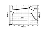
- FIG. 3 is a diagram for explaining control by the electrolytic cell constant voltage constant current power supply circuit 10.
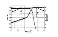
- FIG. 4 is an enlarged view of a switching portion from constant current control to constant voltage control shown in FIG. In FIG. 3 and FIG. 4, the time on the horizontal axis is different, but these drawings show the control under the same conditions performed at different dates.
- FIG. 3 shows electrolysis in the electrolytic cell 1 using the electrolytic cell constant voltage constant current power circuit 10 according to one embodiment of the present invention.
- the horizontal axis represents time
- the left vertical axis represents the electrolytic current (electrolytic current)
- the right vertical axis represents the electrolytic cell voltage.
- the voltage change of the electrolytic cell according to time is shown in the upper stage
- the current change to the electrolytic cell is shown in the lower stage.
- the example shown in FIG. 3 shows an electrolysis cycle for electrolyzing an electrolytic cell 1 filled with hydrochloric acid as an electrolytic solution. Note that the electrolytic solution filled in the electrolytic cell 1 is not limited to hydrochloric acid.
- hydrochloric acid is electrolyzed by two types of control, a constant current control ( ⁇ t1) region and a constant voltage control ( ⁇ t2) region.
- ⁇ t1 constant current control
- ⁇ t2 constant voltage control
- the number of cells in the electrolytic cell 1 is 12 cells
- the maximum current value of the circuit is 2.94 A
- the maximum voltage is 24 V.
- an inrush current overcurrent
- the constant current control described above can maintain a constant current, the inrush current can be prevented.
- electrolytic cell constant voltage constant current power supply circuit 10 shifts from constant current control to constant voltage control.
- a constant voltage (the above-described preset voltage comparison reference voltage) is automatically supplied to the electrolytic cell 1.
- the electrolytic cell constant voltage constant current power supply circuit 10 is under constant voltage control, the current to the electrolytic cell 1 gradually decreases as shown in the region of ⁇ t2 because the concentration of hydrochloric acid decreases with the progress of electrolysis.
- the electrolytic cell 1 is a batch type electrolytic cell, the end of electrolysis can be indicated by using the current detection signal output from the 17th pin 20_17 after reaching the minimum threshold current. It is possible to finish the electrolysis cycle.
- Example 10 An embodiment in which the effective chlorine concentration is controlled using the electrolytic cell constant voltage constant current power supply circuit 10 will be described below with reference to FIGS.
- the DC power source a constant current substrate that can be switched between a current value of 1 A and 3 A was used.
- the electrolytic cell 1 an electrolytic cell having six cells was used. By supplying 9% hydrochloric acid into the electrolytic cell 1, the electrolytic voltage was adjusted to 10 V when an electrolytic current of 3 A was applied to the switching CVCC power supply circuit 20. The average current value was controlled by changing the ratio between the period of 3 A and the period of 1 A of the electrolytic current during one cycle. The length of one cycle is 1 second.
- Chlorine gas generated by electrolysis was injected into water at a flow rate of 20 L / hour.
- pulse control with a duty ratio of 5 patterns was performed as current control.
- the switching CVCC power supply circuit 20 was supplied with a current of 3 A from the constant current substrate when the pulse was on. Further, the switching CVCC power supply circuit 20 was inputted with 1 A of electrolysis current from the constant current substrate when the pulse was off.
- the current control patterns (1) to (5) will be described.
- the current control pattern (1) the period when the input current per cycle is 3A is 0%, and the period when the input current is 1A is 100% (duty ratio is 0%). Therefore, the average current value in the current control pattern (1) is 1A.
- the period when the input current per cycle is 3A is 25%, and the period when the input current is 1A is 75% (duty ratio is 25%). Therefore, the average current value in the current control pattern (2) is 1.5A.
- the period when the input current per cycle is 3A is 50%, and the period when the input current is 1A is 50% (duty ratio is 50%). Therefore, the average current value in the current control pattern (3) is 2A.
- the period when the input current is 3 A per cycle is 75%, and the period when the input current is 1 A is 25% (duty ratio is 75%). Therefore, the average current value in the current control pattern (4) is 2.5A.
- the average current value in the current control pattern (4) is 3A.
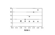
- Table 1 below shows data collected 10 minutes after the start of current control by each of the current control patterns (1) to (5).
- FIG. 6 is a graph showing the data shown in Table 1.
- the triangle mark represents the chlorine concentration (ppm).
- the square mark represents the pH value.
- Table 1 and FIG. 6 a proportional relationship was recognized between the average current value, the effective chlorine concentration, and the pH value. That is, the higher the average current value, the higher the effective chlorine concentration and the lower the pH value. From the above experimental results, it was confirmed that the effective chlorine concentration can be controlled by controlling the average current value.
- the electrolytic cell constant-voltage constant-current power supply circuit 10 is an electrolysis for producing electrolyzed water by electrolyzing raw material water with a current passed between the anode 1a and the cathode 1b.
- This is a power control device that supplies an electrolytic voltage and an electrolytic current to the tank 1 based on the input DC power.
- the electrolytic cell constant voltage constant current power supply circuit 10 is configured so that the electrolytic current does not exceed the current value of a reference current for current comparison (a reference current preset according to the rated current of the unit cell constituting the electrolytic cell 1). It has a constant current control mode for controlling and supplying an electrolytic current to the electrolytic cell 1.
- the electrolytic cell constant voltage constant current power supply circuit 10 is configured such that the electrolytic voltage is a voltage value of a reference voltage for voltage comparison (a reference voltage preset according to the rated voltage and the number of unit cells constituting the electrolytic cell 1). And a constant voltage control mode for supplying an electrolytic voltage to the electrolytic cell. Then, the electrolytic cell constant voltage constant current power supply circuit 10 switches the constant current control mode and the constant voltage control mode to energize the electrolytic cell 1 in accordance with the concentration of the electrolytic solution in the electrolytic cell.
- a reference voltage for voltage comparison a reference voltage preset according to the rated voltage and the number of unit cells constituting the electrolytic cell 1).
- a constant voltage control mode for supplying an electrolytic voltage to the electrolytic cell. Then, the electrolytic cell constant voltage constant current power supply circuit 10 switches the constant current control mode and the constant voltage control mode to energize the electrolytic cell 1 in accordance with the concentration of the electrolytic solution in the electrolytic cell.
- the reference voltage for current comparison and the reference voltage for voltage comparison are A current and a voltage are supplied to the electrolytic cell based on a preset reference value). Therefore, according to the embodiment of the present invention, it is possible to provide a power control apparatus that can be commonly used for electrolytic cells having different cell configurations.
- the current limit resistor 40 (programming resistor) is set to RP1, and the set current is set.
- the comparator circuit 24 is controlled to a value (high-side reference current).
- the current limiting resistor 40 is set to RP1 + RP2, and the current value flowing through the electrolytic cell 1 is set to a set current value exceeding 0 (zero) A (low side). It can be controlled to a value equal to or higher than the reference current and as close to 0 A as possible.
- the current value to the electrolytic cell 1 when OFF is 0A.
- the electrolyte causes a battery action with the electrode, so that the coating of the electrode (particularly the fired electrode) is peeled off, and the life of the electrode is significantly reduced.
- the current limit switching circuit 60 by providing the current limit switching circuit 60, the back electromotive force is not generated by flowing the current at the OFF time. Therefore, it is possible to extend the life of the electrolytic cell 1 by reducing the load on the electrode.
- the electrolytic cell constant voltage constant current power supply circuit 10 can be configured by a minimum of electronic components (resistance, voltage current conversion circuit, comparator, etc.) as described above. Therefore, the electrolytic cell constant voltage constant current power supply circuit 10 according to the embodiment of the present invention can be supplied as a part of a low-cost and compact electrolyzed water production apparatus.
- the power control device of the present invention supplies current and voltage to the electrolytic cell based on a reference value preset according to the rated current, rated voltage, and number of unit cells constituting the electrolytic cell. Therefore, according to the present invention, it is possible to provide a highly versatile power control apparatus that can be commonly used for electrolytic cells having different cell configurations, and a control method for the power control apparatus.
- Electrolytic cell 10 ... Electrolytic cell constant voltage constant current power supply circuit, 20 ... Switching CVCC power supply circuit, 21 ... Voltage current control circuit, 22 ... Voltage control circuit, 23 ... Voltage current detection circuit, 24 ... Amplifier comparator circuit, 25 ... voltage / current monitor circuit, 30 ... current detection resistor, 40 ... current limiting resistor, 50 ... voltage dividing resistor, 60 ... current limit switching circuit, 70 ... thermistor resistor
Landscapes
- Chemical & Material Sciences (AREA)
- Life Sciences & Earth Sciences (AREA)
- Hydrology & Water Resources (AREA)
- Engineering & Computer Science (AREA)
- Environmental & Geological Engineering (AREA)
- Water Supply & Treatment (AREA)
- Organic Chemistry (AREA)
- Chemical Kinetics & Catalysis (AREA)
- Electrochemistry (AREA)
- General Chemical & Material Sciences (AREA)
- Water Treatment By Electricity Or Magnetism (AREA)
- Electrolytic Production Of Non-Metals, Compounds, Apparatuses Therefor (AREA)
Abstract
Description
また、本発明の第4の態様において、上記第3の態様の電力制御装置の電圧制御回路は、パルス信号のオン状態およびオフ状態に対応するようにパルス幅変調された出力電圧信号を前記出力端子から出力する。
通常の定電圧電気分解では、電源から一定電圧を被電解液が充填された電解槽に印加すると、電解初期に大きな電流が流れ、次第に電流が減衰する。そのため、一定の電流に保つためには、被電解液の濃度調整が必要となる。一方、通常の定電流電気分解では、被電解液の濃度調整による電圧調整、或いは電源自体のオン(ON)またはオフ(OFF)制御により電流を調整している。
なお、最大電解電圧(定格電圧)は、電解槽の設計(セル構成)により、1セルあたり2.0V(1.5~2.5V)に設計することが望ましい。また、最大電解電流(定格電流)は、電極の触媒能に応じた電極面積あたりの電流値(電流密度)に設計するのが望ましい。しかし、これらの定格電流、及び定格電圧に限られることなく、電力制御装置は、電解槽のセル構成に係らず、定電流・定電圧電気分解を行うことが可能である。
電解槽定電圧定電流電源回路10は、スイッチングCVCC電源回路20、電流検出抵抗30(電流検出部)、電流制限抵抗40(電流制限部)、電圧分割抵抗50(電圧分割部)、電流制限切替回路60、及びサーミスタ抵抗器70(温度検出部)を含んでいる。
スイッチングCVCC電源回路20の電圧制御回路22は、1番ピン20_1から電解槽1の陽極1aに電力(電解電圧、電解電流)を供給する回路である。電圧制御回路22は、後述するように、定電流モードでは基準電流値を超えないように(即ち、定電流により)、また定電圧モードでは基準電圧値を超えないように(即ち、定電圧により)、電解槽1に対して電力の供給を行う。
また、3番ピン20_3は、電流検出抵抗30の他端に接続されるとともに、図2に示す電圧電流検出回路23の2番ピン23_2に接続される。
ここで、電圧電流検出回路23は、電流検出抵抗30の両端間に生じる電圧(自身の両端間電圧)を、電解槽1を流れる電解電流の電流値に変換し(両端間電圧と抵抗値Rsとから算出し)、変換後の電流値を3番ピン23_3からコンパレータ回路24の1番ピン24_1に対して出力する。
5番ピン20_5は、電解槽1の陽極1aに接続される。また、5番ピン20_5は、図2に示す電圧電流モニタ回路25の1番ピン25_1に接続される。電圧電流モニタ回路25は、一つの機能として、電解槽1に印加される電圧(電解電圧)の電圧値を示すアナログデータを外部へ出力する。
6番ピン20_6は、電流制限抵抗40aの一端に接続される。また、6番ピン20_6は、コンパレータ回路24の2番ピン24_2に接続される。
7番ピン20_7は、電流制限抵抗40aの他端と電流制限抵抗40bの一端との共通接続点に接続される。7番ピン20_7は、図1、及び図2に示すように、14番ピン20_14を介して電流制限切替回路60の1番ピン60_1に接続される。
8番ピン20_8は、電流制限抵抗40bの他端と接続される。また、8番ピン20_8は、コンパレータ回路24の3番ピン24_3に接続される。
式(1)Rprog=Vref(V)×定数k/(Rs(mΩ)×Ielectrolytic)
これより、電流制限抵抗40の各抵抗値RP1、RP2は、電解電流との比較に用いる基準電圧(以下、電流比較用基準電圧とする)と、電解槽1に流したい電流値(それぞれ高側基準電流値、低側基準電流値とする)と、コンパレータ回路24の内部オフセット電圧とを用いて、下記式(2)及び(3)に基づいて設定される。
式(2)RP1=(電流比較用基準電圧×定数k)/(Rs×高側基準電流+内部オフセット電圧)
式(3)RP1+RP2=(電流比較用基準電圧×定数k/(Rs×低側基準電流+内部オフセット電圧)
なお、高側基準電流は、電解槽1に供給する電解電流の上限値であり、低側基準電流は、電解槽1に供給する電解電流の下限値(高側基準電流より電流値が小さく、0よりも大きい電流値)である。また、これらの各基準電流は、コンパレータ回路24の2番ピン24_2と3番ピン24_3との間を流れる電流である。
9番ピン20_9は、電圧分割抵抗50aの一端に接続される。また、9番ピン20_9は、例えば1番ピン20_1に接続され、電解槽1に印加される電解電圧(モニタ電圧Vmoni;検出電圧)が入力される。また、9番ピン20_9は、図2に示すコンパレータ回路24の4番ピン24_4に接続される。
10番ピン20_10は、電圧分割抵抗50aの他端と電圧分割抵抗50bの一端との共通接続点に接続される。この共通接続点は、10番ピン20_10を介して、コンパレータ回路24の5番ピン24_5に接続される。この共通接続点に発生する分圧電圧を、以下ではフィードバック電圧VFBと称する。
11番ピン20_11は、電圧分割抵抗50bの他端と接続される。また、11番ピン20_11は、GND端子であり、0Vに接続される。11番ピン20_11は、コンパレータ回路24の6番ピン24_6に接続される。
電圧分割抵抗50の各抵抗値R1、R2は、コンパレータ回路24が有する、例えば帰還誤差アンプにおいて、電解電圧との比較に用いる基準電圧(電圧比較用基準電圧とする)と、電解槽1にそれ以上は印加したくない電圧値(電解槽の最大電圧値とする)とを用いて、下記式(4)に基づいて設定される。
式(4) 電解槽の最大電圧値=電圧比較用基準電圧×(1+R1/R2)
つまり、電圧分割抵抗50は、9番ピン20_9において、1番ピン20_1(制御端子)の電圧をモニタ電圧Vmoniとして検出する。電圧分割抵抗50は、この検出したモニタ電圧Vmoniを分圧することによりフィードバック電圧VFBを、10番ピン20_10に発生させる。電圧分割抵抗50は、フィードバック電圧VFBをコンパレータ回路24の5番ピン24_5に対して出力する。コンパレータ回路24は、このフィードバック電圧VFBが入力され、フィードバック電圧VFBと上記の電圧比較用基準電圧とを比較する。
これら15番ピン20_15~17番ピン20_17は、図2に示すように電圧電流モニタ回路25の出力端子である3番ピン25_3~5番ピン25_5にそれぞれ接続される。
電圧電流モニタ回路25において、1番ピン25_1は、上述のようにスイッチングCVCC電源回路20の5番ピン20_5に接続される。また、2番ピン25_2は、コンパレータ回路24の8番ピン24_8に接続される。
また、電圧電流モニタ回路25は、コンパレータ回路24から入力される電解槽に流れる電流(電圧電流検出回路23による変換後の電流)を示すアナログデータを、4番ピン25_4からスイッチングCVCC電源回路20の16番ピン20_16を介して、外部へ出力する。
また、電圧電流モニタ回路25は、コンパレータ回路24から入力される比較結果(電圧電流検出回路23による変換後の電流が上記高側基準電流を下回っているとの結果)に基づいて、スイッチングCVCC電源回路20が定電流を電解槽1に供給していないことを示す電流検出信号を、5番ピン25_5からスイッチングCVCC電源回路20の17番ピン20_17を介して、外部へ出力する。なお、この電流検出信号の形式は、異常を示す場合に接点(ピン)をONする(例えばHレベルとする)形式であってもよく、また、フェ―ルセーフの観点から通常時にHレベルにし、異常時にLレベルとする形式であってもよい。
コンパレータ回路24は、サーミスタ抵抗器70で検出する温度(検出温度)が、電解槽1の予め設定される定格温度の範囲外になると、電気分解を一時停止することを指示する制御信号を電圧制御回路22に対して出力する。電圧制御回路22は、この制御信号が入力されると電解槽1への電圧供給を停止し、電解槽1は電気分解を停止する。また、コンパレータ回路24は、サーミスタ抵抗器70の検出温度が、定格温度の範囲内に戻ると、電気分解を再開することを指示する制御信号を電圧制御回路22に対して出力する。電圧制御回路22は、この制御信号が入力されると電解槽1への電圧供給を再開し、電解槽1は自動的に電気分解を開始する。
コンパレータ回路24は、1番ピン24_1に入力される電圧電流検出回路23による変換後の電流(電解電流)と、1番ピン24_1と3番ピン24_3との間に流れる電流(電流制限抵抗40に流れる高側基準電流、及び低側基準電流)とを比較し、比較結果を表す電流比較結果信号を9番ピン24_9から出力する。
また、コンパレータ回路24は、5番ピン24_5に入力されるフィードバック電圧VFBと電圧比較用基準電圧(予め設定される基準電圧)とを比較し、比較結果を表す電圧比較結果信号を9番ピン24_9から出力する。
電圧制御回路22は、2番ピン22_2から入力される電流比較結果信号に基づいて、電圧電流検出回路23による変換後の電流(電解電流)が高側基準電流を超えないように、1番ピン22_1からスイッチングCVCC電源回路20の1番ピン20_1を介して、電解電流を電解槽1へ供給する。即ち、電圧制御回路22は、定電流を電解槽1に供給する。また、電圧制御回路22は、電流比較結果信号に基づいて、電解電流が低側基準電流を下回らないように、1番ピン22_1からスイッチングCVCC電源回路20の1番ピン20_1を介して、電解電流を電解槽1へ供給する。
(定電流制御モード)
電解槽1における電解電流の制御は、電流検出抵抗30によって検出された電解電流が、設定された最大電解電流(高側基準電流)を超えないように制御して、行われる。例えば、被電解液が充填された電解槽1に、スイッチングCVCC回路20の1番ピン20_1から出力電圧Voutを印加すると、電流検出抵抗30が、電解槽1への出力電流を感知する。電流検出抵抗(センス抵抗)は、両端の電圧を測定し、例えば電圧電流検出回路23における電流アンプで電圧を電流信号に変換し、その電流信号をコンパレータ回路24に対して出力する。
電解槽1において被電解液の濃度が薄くなると、定電流を維持するために電圧が上昇する。最大電解電圧に到達すると、上述のように電圧レギュレート機能が働き、定電圧の制御に切替える。最大電解電圧レベルは、コンパレータ回路24に予め設定された電圧比較用基準電圧と、コンパレータ回路24にある、例えば帰還誤差アンプの入力との間に設けられる電圧分割抵抗50(帰還抵抗分割)を使い、設定されている。この電圧分割抵抗50のフィードバック電圧VFBは、上述のようにコンパレータ回路24内の電圧帰還誤差アンプによって、基準電圧と比較され、電圧制御回路22の1番ピン20_1からの出力電圧を制御する。
続いて、電解槽1における被電解液の濃度の変化に応じて、定電流制御モードと定電圧制御モードとを切り替えて電解槽1に印加電圧を供給する電解槽定電圧定電流電源回路10の動作について、図3、及び図4を参照して説明する。図3は、電解槽定電圧定電流電源回路10による制御を説明するための図である。また、図4は、図3に示す定電流制御から定電圧制御への切り替わり部分を拡大した図である。なお、図3と図4においては、横軸の時間が異なるが、これらの図は、異なる日時において行った、同一条件での制御を示している。
図3は、本発明の一実施形態による電解槽定電圧定電流電源回路10を用いた電解槽1における電気分解を示している。図3に示すグラフは、横軸を時間とし、左の縦軸に電解電流(電解電流)、右の縦軸に電解槽の電圧をプロットしたものである。
図3では、時間に応じた電解槽の電圧変化を上段に示し、電解槽への電流変化を下段に示している。この図3に示す例は、被電解液として塩酸が充填された電解槽1を電気分解する電解サイクルを示している。なお、電解槽1に充填される被電解液は、塩酸に限らない。
電解槽1においては、定電流制御(Δt1)の領域と定電圧制御(Δt2)の領域の2種類の制御で塩酸が電気分解される。
なお、図3に示す例では、電解槽1のセル数は12セルで、回路の最大電流値が2.94Aに、最大電圧が24Vになるように設計されている。電解槽1に塩酸が過剰に充填されていると、通常、突入電流(過電流)が発生するが、上述した定電流制御により一定の電流に維持できるため、突入電流を防止することができる。
このとき、電解槽1がバッチ式の電解槽であれば、最小閾値の電流に達した後に、17番ピン20_17から出力される電流検出信号を利用して、電気分解の終了を示すことができ、電気分解のサイクルを終えることが可能である。
また、電解槽1の電圧が増加するとき(図4に示すΔVの範囲)、電流が一定に保たれる。そのことを利用して、適量の塩酸を電解槽1に供給することにより、定電流の連続式電気分解を行うことも可能である。
電解槽定電圧定電流電源回路10を用いて、有効塩素濃度の制御を行った実施例について、図5および6並びに表1を参照して以下に説明する。
直流電源として、電流値が1Aと3Aで切り替え可能な定電流基板を用いた。電解槽1として、セルの数が6個の電解槽を用いた。電解槽1中に9%塩酸を供給することにより、スイッチングCVCC電源回路20に3Aの電解電流を印加した際の電解電圧が10Vになるよう調整した。1サイクル中における電解電流の電流値が3Aの期間と1Aの期間の比率を変化させることより平均電流値を制御した。1サイクルの長さは1秒である。電気分解によって発生した塩素ガスを、毎時20Lの流量の水に注入した。
図5に示すように、電流制御として5パターンのデューティ比のパルス制御を行った。スイッチングCVCC電源回路20には、パルスがオン状態において、3Aの電流が定電流基板から入力された。また、スイッチングCVCC電源回路20には、パルスがオフ状態において、1Aの電解電流が定電流基板から入力された。
次に、電流制御パターン(1)~(5)について説明する。
電流制御パターン(1)において、1サイクル当たりにおける入力電流が3Aの期間が0%で、入力電流が1Aの期間が100%である(デューティ比が0%)。よって、電流制御パターン(1)における平均電流値は1Aである。
電流制御パターン(2)において、1サイクル当たりにおける入力電流が3Aの期間が25%で、入力電流が1Aの期間が75%である(デューティ比が25%)。よって、電流制御パターン(2)における平均電流値は1.5Aである。
電流制御パターン(3)において、1サイクル当たりにおける入力電流が3Aの期間が50%で、入力電流が1Aの期間が50%である(デューティ比が50%)。よって、電流制御パターン(3)における平均電流値は2Aである。
電流制御パターン(4)の電流制御において、1サイクル当たりにおける入力電流が3Aの期間が75%で、入力電流が1Aの期間が25%である(デューティ比が75%)。よって、電流制御パターン(4)における平均電流値は2.5Aである。
電流制御パターン(4)の電流制御において、1サイクル当たりにおける入力電流が3Aの期間が100%で、入力電流が1Aの期間が0%である(デューティ比が100%)。よって、電流制御パターン(4)における平均電流値は3Aである。
下記の表1は、電流制御パターン(1)~(5)各々による電流制御の開始から10分後に採取したデータを示す。

図6は、表1に示すデータをグラフで表している。図6において、三角印は、塩素濃度(ppm)を表している。また、四角印は、pH値を表している。
表1および図6から明らかなように平均電流値と有効塩素濃度およびpH値とには比例関係が認められた。すなわち、平均電流値が高いほど、有効塩素濃度が高くなりまたpH値が低くなった。以上の実験結果から、平均電流値を制御することにより、有効塩素濃度を制御できることが確認された。
一方、本発明の実施形態では、電流制限切替回路60を備えることにより、OFF時に電流を流すことによって、逆起電力が発生することがなくなる。そのため、電極への負荷を低減することにより、電解槽1の寿命を延ばすことが可能となる。
Claims (8)
- 陽極と陰極との間に通電される電流によって原料水を電気分解して電解水を製造するための電解槽に対して、入力される直流電力に基づいて、電解電圧、及び電解電流を供給する電力制御装置であって、
定電流制御モードにおいて、前記電解電流が、前記電解槽を構成する単位セルの定格電流に応じて予め設定される基準電流の電流値を超えないように制御しながら前記電解電流を前記電解槽へ供給し、
定電圧制御モードにおいて、前記電解電圧が、前記電解槽を構成する単位セルの定格電圧、及び個数に応じて予め設定される基準電圧の電圧値を超えないように制御しながら前記電解電圧を前記電解槽へ供給する電圧電流制御回路を備え、
前記電圧電流制御回路は、前記電解槽内の被電解液の濃度に応じて、前記定電流制御モードと前記定電圧制御モードとを切り替える、電力制御装置。 - 前記電圧電流制御回路の出力端子に接続され、自身の両端間に生じる電圧を検出する電流検出部と、
前記基準電流を生成する電流制限部と、
前記出力端子の電圧を検出し、前記検出した電圧を分圧することによりフィードバック電圧を発生する電圧分割部とをさらに備え、
前記電圧電流制御回路は、
前記電流検出部の両端間電圧と前記電流検出部の抵抗値とから前記電解槽に流れる前記電解電流を算出する電圧電流検出回路と、
前記電解電流と前記電流制限部よって生成される前記基準電流とを比較し、比較結果を表す電流比較結果信号を出力するとともに、前記フィードバック電圧と前記基準電圧とを比較し、比較結果を表す電圧比較結果信号を出力するコンパレータ回路と、
前記電流比較結果信号に基づいて、前記電解電流が前記基準電流を超えないように制御しながら前記出力端子から前記電解電流を前記電解槽へ供給するとともに、前記電圧比較結果信号に基づいて、前記フィードバック電圧が前記基準電圧を超えないように制御しながら前記電解電圧を前記電解槽へ供給する電圧制御回路と、を有する
請求項1に記載の電力制御装置。 - 外部から入力されるデューティ比が制御されたパルス信号がオン状態であることに応じて前記基準電流を前記電流制限部に生成させ、前記パルス信号がオフ状態であることに応じて前記基準電流より低く、ゼロよりも大きい値を有する低側基準電流を、前記電流制限部に生成させる電流制限切り替え回路をさらに備え、
前記コンパレータ回路は、前記電解電流と前記電流制限部に流れる前記低側基準電流とを比較し、比較結果を表す前記電流比較結果信号を出力し、
前記電圧制御回路は、前記電流比較結果信号に基づいて、前記電解電流が前記低側基準電流を下回らないように制御しながら前記出力端子から前記電解電流を前記電解槽へ供給する、
請求項2に記載の電力制御装置。 - 前記電圧制御回路は、前記パルス信号のオン状態およびオフ状態に対応するようにパルス幅変調された出力電圧信号を前記出力端子から出力する
請求項3に記載の電力制御装置。 - 前記電解電流の電流値を示すアナログデータと、前記電解電圧の電圧値を示すアナログデータと、前記電解電流の電流値が前記基準電流を下回ったことを示す電流検出信号とを、外部へ出力する電圧電流モニタ回路を、
さらに備える請求項2に記載の電力制御装置。 - 前記電解電流の電流値を示すアナログデータと、前記電解電圧の電圧値を示すアナログデータと、前記電解電流の電流値が前記基準電流を下回ったことを示す電流検出信号とを、外部へ出力する電圧電流モニタ回路を、
さらに備える請求項3に記載の電力制御装置。 - 前記電解槽の温度を検出する温度検出部をさらに備え、
前記電圧電流制御回路は、前記温度検出部の検出温度が、予め設定される定格温度範囲外になると、電解電圧、及び電解電流の供給を停止し、
前記電圧電流制御回路は、前記温度検出部の検出温度が、前記定格温度範囲内に戻ると、電解電圧、及び電解電流の供給を再開する、
請求項1に記載の電力制御装置。 - 陽極と陰極との間に通電される電流によって原料水を電気分解して電解水を製造するための電解槽に対して、入力される直流電力に基づいて、電解電圧、及び電解電流を供給する電力制御装置の制御方法であって、
前記電解電流が、前記電解槽を構成する単位セルの定格電流に応じて予め設定される基準電流の電流値を超えないように制御しながら前記電解電流を前記電解槽へ供給する定電流制御ステップと、
前記電解電圧が、前記電解槽を構成する単位セルの定格電圧、及び個数に応じて予め設定される基準電圧の電圧値を超えないように制御しながら前記電解電圧を前記電解槽へ供給する定電圧制御ステップと、を有し、
前記電解槽内の被電解液の濃度に応じて、前記定電流制御ステップと前記定電圧制御ステップとを切り替える
電力制御装置の制御方法。
Priority Applications (5)
| Application Number | Priority Date | Filing Date | Title |
|---|---|---|---|
| KR1020157034743A KR101647326B1 (ko) | 2013-06-10 | 2014-06-09 | 전력 제어 장치, 및 전력 제어 장치의 제어 방법 |
| EP14811616.3A EP3009406A4 (en) | 2013-06-10 | 2014-06-09 | POWER CONTROL DEVICE AND CONTROL METHOD FOR POWER CONTROL DEVICE |
| US14/896,143 US9944543B2 (en) | 2013-06-10 | 2014-06-09 | Power control device and control method for power control device |
| CN201480033007.1A CN105339309B (zh) | 2013-06-10 | 2014-06-09 | 电力控制装置以及电力控制装置的控制方法 |
| JP2014554637A JP5728626B1 (ja) | 2013-06-10 | 2014-06-09 | 電力制御装置、及び電力制御装置の制御方法 |
Applications Claiming Priority (2)
| Application Number | Priority Date | Filing Date | Title |
|---|---|---|---|
| JP2013121626 | 2013-06-10 | ||
| JP2013-121626 | 2013-06-10 |
Publications (1)
| Publication Number | Publication Date |
|---|---|
| WO2014199950A1 true WO2014199950A1 (ja) | 2014-12-18 |
Family
ID=52022243
Family Applications (1)
| Application Number | Title | Priority Date | Filing Date |
|---|---|---|---|
| PCT/JP2014/065226 Ceased WO2014199950A1 (ja) | 2013-06-10 | 2014-06-09 | 電力制御装置、及び電力制御装置の制御方法 |
Country Status (7)
| Country | Link |
|---|---|
| US (1) | US9944543B2 (ja) |
| EP (1) | EP3009406A4 (ja) |
| JP (1) | JP5728626B1 (ja) |
| KR (1) | KR101647326B1 (ja) |
| CN (1) | CN105339309B (ja) |
| TW (1) | TWI509110B (ja) |
| WO (1) | WO2014199950A1 (ja) |
Cited By (2)
| Publication number | Priority date | Publication date | Assignee | Title |
|---|---|---|---|---|
| WO2016061997A1 (zh) | 2014-10-21 | 2016-04-28 | 中兴通讯股份有限公司 | 一种天线结构 |
| WO2016076158A1 (ja) * | 2014-11-11 | 2016-05-19 | 森永乳業株式会社 | 組込装置及び、組込装置の制御方法 |
Families Citing this family (10)
| Publication number | Priority date | Publication date | Assignee | Title |
|---|---|---|---|---|
| SG10202109754TA (en) | 2017-03-06 | 2021-10-28 | Evoqua Water Tech Llc | Implementation of feedback control for improved electrochemical system design |
| KR102111304B1 (ko) * | 2018-08-09 | 2020-05-18 | (주)선우하이테크 | 정전류 제어기능을 갖는 전기 도금 시스템 및 방법 |
| CN110306200B (zh) * | 2019-06-14 | 2024-04-16 | 深圳市珐彩科技有限公司 | 一种电解装置及基于电解装置的电压控制方法 |
| CN110240234A (zh) * | 2019-06-18 | 2019-09-17 | 广东顺德清宇环保科技有限公司 | 用于水处理装置的控制方法和水处理装置 |
| CN110670086B (zh) * | 2019-09-12 | 2023-10-24 | 佛山顺德歌林美电子产品有限公司 | 一种电子筛保鲜装置的恒压恒流方法 |
| CN112267127B (zh) * | 2020-11-10 | 2023-12-22 | 珠海格力电器股份有限公司 | 一种电解控制电路、消毒液制造装置及电解控制方法 |
| CN113406912A (zh) * | 2021-07-12 | 2021-09-17 | 珠海格力电器股份有限公司 | 消毒液制造机控制装置及消毒液制造机 |
| CN116022889B (zh) * | 2021-10-26 | 2025-08-22 | 佛山市顺德区美的电子科技有限公司 | 电解水电路、电解水设备及其控制方法、存储介质 |
| CN114243714B (zh) * | 2021-11-30 | 2026-03-10 | 清华大学 | 电解槽控制方法、装置、计算机设备和存储介质 |
| WO2024184921A1 (en) * | 2023-03-03 | 2024-09-12 | Openwater.In Private Limited | System and method for water treatment |
Citations (6)
| Publication number | Priority date | Publication date | Assignee | Title |
|---|---|---|---|---|
| JPH0721188U (ja) * | 1993-09-14 | 1995-04-18 | 株式会社セイロジャパン | 連続式アルカリイオン水生成器の電解強度制御装置 |
| JPH11128942A (ja) * | 1997-10-30 | 1999-05-18 | Trp:Kk | 水質浄化方法及びその機構 |
| JP2003154367A (ja) * | 2001-11-21 | 2003-05-27 | Asahi Glass Engineering Co Ltd | 冷却水系の水処理方法及び水処理装置 |
| JP2006130505A (ja) * | 2005-12-05 | 2006-05-25 | Sharp Corp | イオン溶出ユニット及びそれを備えた機器 |
| JP2009072659A (ja) * | 2007-09-19 | 2009-04-09 | Honda Motor Co Ltd | 電解水生成方法及び装置 |
| JP2012246553A (ja) | 2011-05-30 | 2012-12-13 | Mitsubishi Heavy Industries Environmental & Chemical Engineering Co Ltd | 海水電解システム及び海水電解方法 |
Family Cites Families (8)
| Publication number | Priority date | Publication date | Assignee | Title |
|---|---|---|---|---|
| JPH0721188A (ja) | 1993-07-02 | 1995-01-24 | Oki Electric Ind Co Ltd | 電子翻訳装置 |
| CN1097560C (zh) | 1995-12-27 | 2003-01-01 | 日本恩迪克股份有限公司 | 电解水生成器 |
| US20040121204A1 (en) * | 2001-06-07 | 2004-06-24 | Adelman Marc D. | Fluid electrical connected flow-through electrochemical cells, system and method |
| JP3835360B2 (ja) * | 2002-06-26 | 2006-10-18 | 松下電工株式会社 | 電解水生成装置 |
| JP3714945B1 (ja) * | 2004-07-27 | 2005-11-09 | シャープ株式会社 | 金属イオン溶出ユニット及びこれを備えた電気機器 |
| JP2012240026A (ja) * | 2011-05-24 | 2012-12-10 | Panasonic Corp | 電解水生成装置 |
| KR101893006B1 (ko) * | 2011-10-14 | 2018-10-05 | 삼성전자주식회사 | 전해 환원수 장치 및 그 제어 방법 |
| JP2013091819A (ja) * | 2011-10-24 | 2013-05-16 | Toyo Tanso Kk | 電解装置 |
-
2014
- 2014-06-09 WO PCT/JP2014/065226 patent/WO2014199950A1/ja not_active Ceased
- 2014-06-09 KR KR1020157034743A patent/KR101647326B1/ko not_active Expired - Fee Related
- 2014-06-09 CN CN201480033007.1A patent/CN105339309B/zh not_active Expired - Fee Related
- 2014-06-09 JP JP2014554637A patent/JP5728626B1/ja active Active
- 2014-06-09 US US14/896,143 patent/US9944543B2/en not_active Expired - Fee Related
- 2014-06-09 EP EP14811616.3A patent/EP3009406A4/en not_active Ceased
- 2014-06-10 TW TW103120053A patent/TWI509110B/zh not_active IP Right Cessation
Patent Citations (6)
| Publication number | Priority date | Publication date | Assignee | Title |
|---|---|---|---|---|
| JPH0721188U (ja) * | 1993-09-14 | 1995-04-18 | 株式会社セイロジャパン | 連続式アルカリイオン水生成器の電解強度制御装置 |
| JPH11128942A (ja) * | 1997-10-30 | 1999-05-18 | Trp:Kk | 水質浄化方法及びその機構 |
| JP2003154367A (ja) * | 2001-11-21 | 2003-05-27 | Asahi Glass Engineering Co Ltd | 冷却水系の水処理方法及び水処理装置 |
| JP2006130505A (ja) * | 2005-12-05 | 2006-05-25 | Sharp Corp | イオン溶出ユニット及びそれを備えた機器 |
| JP2009072659A (ja) * | 2007-09-19 | 2009-04-09 | Honda Motor Co Ltd | 電解水生成方法及び装置 |
| JP2012246553A (ja) | 2011-05-30 | 2012-12-13 | Mitsubishi Heavy Industries Environmental & Chemical Engineering Co Ltd | 海水電解システム及び海水電解方法 |
Non-Patent Citations (1)
| Title |
|---|
| See also references of EP3009406A4 * |
Cited By (3)
| Publication number | Priority date | Publication date | Assignee | Title |
|---|---|---|---|---|
| WO2016061997A1 (zh) | 2014-10-21 | 2016-04-28 | 中兴通讯股份有限公司 | 一种天线结构 |
| WO2016076158A1 (ja) * | 2014-11-11 | 2016-05-19 | 森永乳業株式会社 | 組込装置及び、組込装置の制御方法 |
| JP2016087591A (ja) * | 2014-11-11 | 2016-05-23 | 森永乳業株式会社 | 組込装置及び、組込装置の制御方法 |
Also Published As
| Publication number | Publication date |
|---|---|
| CN105339309B (zh) | 2017-03-08 |
| TW201512459A (zh) | 2015-04-01 |
| CN105339309A (zh) | 2016-02-17 |
| US9944543B2 (en) | 2018-04-17 |
| KR101647326B1 (ko) | 2016-08-10 |
| TWI509110B (zh) | 2015-11-21 |
| KR20160003285A (ko) | 2016-01-08 |
| JP5728626B1 (ja) | 2015-06-03 |
| JPWO2014199950A1 (ja) | 2017-02-23 |
| EP3009406A4 (en) | 2016-12-28 |
| US20160115047A1 (en) | 2016-04-28 |
| EP3009406A1 (en) | 2016-04-20 |
Similar Documents
| Publication | Publication Date | Title |
|---|---|---|
| JP5728626B1 (ja) | 電力制御装置、及び電力制御装置の制御方法 | |
| JP6031489B2 (ja) | 組込装置及び、組込装置の制御方法 | |
| CN110240234A (zh) | 用于水处理装置的控制方法和水处理装置 | |
| CA2828788A1 (en) | Capacitive charging power source for electrolytic reactors | |
| CN211999938U (zh) | 一种电极过流保护电路、电解电路及消毒液制造机 | |
| CN112267127B (zh) | 一种电解控制电路、消毒液制造装置及电解控制方法 | |
| CN213708502U (zh) | 一种电解控制电路及消毒液制造装置 | |
| CN106011919A (zh) | 一种自适应调节制氢发生装置驱动电路 | |
| CN216526924U (zh) | 基于硬件控制的恒流输出电路及电解装置 | |
| CN215288991U (zh) | 一种电解控制电路、消毒液制造装置 | |
| KR200354136Y1 (ko) | 전기분해를 이용한 이온 환원수 및 산화수 생성장치 | |
| HK1239652A1 (en) | Incorporated device and method for controlling incorporated device | |
| CN204423041U (zh) | 一种电解银离子释放量控制电路 | |
| CN104570884A (zh) | 一种电解银离子释放量控制电路及其方法 | |
| CN216959372U (zh) | 用于电解水的电压自动调节的供电电路和电解水设备 | |
| JP2646937B2 (ja) | イオン水生成器の電解制御装置 | |
| JP2014512651A (ja) | 燃料電池発電装置の制御 | |
| KR101404450B1 (ko) | 전압을 제어하는 전기 분해 살균 장치 | |
| RU2338314C1 (ru) | Способ стабилизации тока серии алюминиевых электролизеров | |
| Gangothri et al. | Design of compact controller and power module for corrosion and marine growth prevention | |
| JP2004091833A (ja) | 電解槽制御方法および装置 | |
| JP2017056374A (ja) | 電解水生成装置 | |
| CN113406912A (zh) | 消毒液制造机控制装置及消毒液制造机 | |
| CN111875005A (zh) | 一种污水处理系统、污水处理方法及可调节电源 | |
| KR101069982B1 (ko) | 살균성능이 균일한 살균수 생성장치 |
Legal Events
| Date | Code | Title | Description |
|---|---|---|---|
| WWE | Wipo information: entry into national phase |
Ref document number: 201480033007.1 Country of ref document: CN |
|
| ENP | Entry into the national phase |
Ref document number: 2014554637 Country of ref document: JP Kind code of ref document: A |
|
| 121 | Ep: the epo has been informed by wipo that ep was designated in this application |
Ref document number: 14811616 Country of ref document: EP Kind code of ref document: A1 |
|
| WWE | Wipo information: entry into national phase |
Ref document number: 14896143 Country of ref document: US |
|
| ENP | Entry into the national phase |
Ref document number: 20157034743 Country of ref document: KR Kind code of ref document: A |
|
| WWE | Wipo information: entry into national phase |
Ref document number: 2014811616 Country of ref document: EP |
|
| NENP | Non-entry into the national phase |
Ref country code: DE |
|
| WWE | Wipo information: entry into national phase |
Ref document number: IDP00201508368 Country of ref document: ID |