WO2014207931A1 - Système et procédé de communication - Google Patents
Système et procédé de communication Download PDFInfo
- Publication number
- WO2014207931A1 WO2014207931A1 PCT/JP2013/067923 JP2013067923W WO2014207931A1 WO 2014207931 A1 WO2014207931 A1 WO 2014207931A1 JP 2013067923 W JP2013067923 W JP 2013067923W WO 2014207931 A1 WO2014207931 A1 WO 2014207931A1
- Authority
- WO
- WIPO (PCT)
- Prior art keywords
- information
- receiving
- port
- unit
- identification information
- Prior art date
- Legal status (The legal status is an assumption and is not a legal conclusion. Google has not performed a legal analysis and makes no representation as to the accuracy of the status listed.)
- Ceased
Links
Images


Classifications
-
- H—ELECTRICITY
- H04—ELECTRIC COMMUNICATION TECHNIQUE
- H04N—PICTORIAL COMMUNICATION, e.g. TELEVISION
- H04N21/00—Selective content distribution, e.g. interactive television or video on demand [VOD]
- H04N21/40—Client devices specifically adapted for the reception of or interaction with content, e.g. set-top-box [STB]; Operations thereof
- H04N21/43—Processing of content or additional data, e.g. demultiplexing additional data from a digital video stream; Elementary client operations, e.g. monitoring of home network or synchronising decoder's clock; Client middleware
- H04N21/436—Interfacing a local distribution network, e.g. communicating with another STB or one or more peripheral devices inside the home
- H04N21/43615—Interfacing a Home Network, e.g. for connecting the client to a plurality of peripherals
-
- H—ELECTRICITY
- H04—ELECTRIC COMMUNICATION TECHNIQUE
- H04N—PICTORIAL COMMUNICATION, e.g. TELEVISION
- H04N21/00—Selective content distribution, e.g. interactive television or video on demand [VOD]
- H04N21/40—Client devices specifically adapted for the reception of or interaction with content, e.g. set-top-box [STB]; Operations thereof
- H04N21/41—Structure of client; Structure of client peripherals
- H04N21/4104—Peripherals receiving signals from specially adapted client devices
- H04N21/4108—Peripherals receiving signals from specially adapted client devices characterised by an identification number or address, e.g. local network address
Definitions
- Embodiments of the present invention relate to a communication system and method.
- MHL Mobile High-Definition Link
- a repeater device such as an amplifier can be connected between a portable device that is a source device and a television that is a sink device.
- a plurality of source devices can be connected to such a repeater device.
- RCP Remote Control Protocol
- the sink device transmits an RCP control command to the source device, and the source device executes the RCP command, thereby enabling remote operation between the devices.
- the MHL standard only defines that the sink device and the source device are connected at a ratio of 1: 1, and when the sink device and the source device are connected in a many-to-many manner with a repeater device interposed therebetween. Has a problem that a control command cannot be transmitted from the sink device to all of the plurality of source devices.
- the present invention has been made in view of the above, and enables transmission of a control command from a source device to a plurality of source devices even when the sink device and the source device are connected in a one-to-many manner. It is a main object of the present invention to provide a communication system and method capable of smoothly controlling the above.
- the communication system includes a transmission device that transmits a command, and a relay device that is connected between the transmission device and a plurality of reception devices that receive and execute the command.
- the relay device includes a first reception unit, a device list management unit, and a first transmission unit.
- the first receiving unit receives model information of each device from each of the plurality of receiving devices.
- the device list management unit includes, for each port identification information for identifying a port connecting each of the plurality of reception devices, device identification information for identifying the reception device and position information regarding the position of the relay device Device list information is generated.
- the first transmission unit transmits the device list information to the transmission device.
- the transmission device includes a second reception unit and a second transmission unit.
- the second transmission unit receives the device list information.
- the second transmission unit receives the command in which the port identification information corresponding to the device identification information of the receiving device to be accessed and the location information of the relay device are specified in the device list information. Send to.
- FIG. 1 is a configuration diagram of a communication system according to the first embodiment.
- FIG. 2 is a block diagram illustrating a functional configuration of the repeater device according to the first embodiment.
- FIG. 3 is a diagram illustrating an example of device list data according to the first embodiment.
- FIG. 4 is a block diagram illustrating a configuration of the digital television according to the first embodiment.
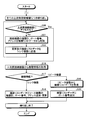
- FIG. 5 is a flowchart illustrating a communication processing procedure performed by the repeater device according to the first embodiment.
- FIG. 6 is a diagram illustrating an example of the MHL topology according to the first embodiment.
- FIG. 7 is a diagram illustrating an example of device list data according to the first embodiment.
- FIG. 8 is a diagram illustrating an example of device list data according to the first embodiment.
- FIG. 1 is a configuration diagram of a communication system according to the first embodiment.
- FIG. 2 is a block diagram illustrating a functional configuration of the repeater device according to the first embodiment.
- FIG. 3 is a diagram illustrating
- FIG. 9 is a diagram illustrating an example of device list data according to the first embodiment.
- FIG. 10 is a sequence diagram illustrating a communication processing procedure performed by the sink device and the repeater device according to the first embodiment.
- FIG. 11 is a diagram illustrating an example of a source device selection screen according to the first embodiment.
- FIG. 12 is a diagram illustrating an example in which a source device connected to a repeater device is disconnected.
- FIG. 13 is a flowchart illustrating a communication processing procedure performed by the repeater device according to the second embodiment.
- FIG. 14 is a sequence diagram illustrating a communication processing procedure between the repeater device and the sink device according to the second embodiment.
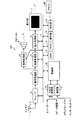
- the communication system of this embodiment has a configuration in which a plurality of portable devices 200a to 200n, a digital television 100, and a repeater device 400 are connected by an MHL cable 300.
- Video transmission via the repeater device 400 between the plurality of mobile devices 200a to 200n and the digital television 100 is realized in conformity with the MHL standard. More specifically, in the present embodiment, a plurality of portable devices 200a to 200n serve as source devices, and the digital television 100 serves as a sink device, and video data is transferred from the plurality of portable devices 200a to 200n via the repeater device 400. At 300, the data is transmitted to the digital television 100 using the protocol of the MHL standard.
- each of the plurality of portable devices 200a to 200n functions as a receiving device, and the digital television 100 functions as a transmitting device.
- the repeater device 400 functions as a relay device.
- the digital television 100 transmits an RCP command, which is a remote command, to the plurality of portable devices 200 via the repeater device 400, and the portable device 200 receives and executes the RCP command.
- the plurality of mobile devices 200a to 200n are collectively referred to as a plurality of mobile devices 200.
- a digital television 100 equipped with a digital broadcast receiving tuner will be described as an example of a communication device (transmission device).
- the present invention is not limited to the digital television 100, and may be a device such as a hard disk recorder or a set top box that includes a tuner that receives broadcast waves, processes video, and outputs it to an externally connected display device.
- a monitor that does not include a tuner and that receives video and audio from an external tuner may be used.
- the portable device 200 is exemplified as a receiving device, the present invention is not limited to this, and a device other than the portable device 200 may be used as the receiving device.
- the portable device 200 is the source device and the digital television 100 is the sink device, but this is also an example, and the present invention is not limited to this combination.
- the repeater device 400 of this embodiment corresponds to, for example, an amplifier, but is not limited to this.
- the repeater device 400 according to the present embodiment includes a communication unit 401, a determination unit 402, an address determination unit 403, a device list management unit 404, an input switching unit 407, and device list data 405. Management information 406 is mainly provided.
- each of a plurality of source devices (such as the portable terminal 200 in this embodiment) is connected to the port 408.
- a plurality of source devices (portable devices 200) side is referred to as an upstream side (upstream side), and a sink device (digital television 100) side is referred to as a downstream side (downstream side).
- 1 and 2 show a configuration in which the mobile device 200, that is, the source device is connected to the upstream side, but other repeater devices may be connected to the upstream side.
- 1 and 2 show a configuration in which the digital television 100, that is, a sink device is connected to the downstream side, but other repeater devices may be connected to the downstream side. Therefore, hereinafter, devices connected to the upstream side of the repeater device 400 are referred to as upstream-side connected devices including the mobile device 200, other source devices, and other repeater devices.
- Devices connected to the downstream side may be referred to as downstream-side connected devices including the digital TV 100 and other repeater devices.
- the management information 406 includes an address indicating the position of the repeater device 400 on the MHL topology and model information. As the model information, “repeater device” is set. Management information is stored in the capability register. However, the present invention is not limited to this, and the management information may be stored in a storage medium such as a memory.
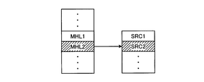
- the model information is stored in each capability register of a source device such as the portable terminal 200 and a sink device such as the digital TV 100 with settings corresponding to each device.
- the model information of the source device such as the portable terminal 200 is set to “source device”, and the model information of the sink device such as the digital TV 100 is set to “sink device”.
- the communication unit 401 requests model information from a plurality of connected devices on the upstream side and a plurality of connected devices on the downstream side, and receives model information stored in the capability register of each connected device as a response.
- the communication unit 401 receives device list data described later from the connected device, that is, another repeater device. Receive.
- the communication unit 401 receives various RCP commands from the digital television 100 which is a sink device.
- the communication unit 401 transmits its device list data to the digital television 100.
- the communication unit 401 sends the RCP command from the port 408 of the port number to the source device (mobile phone) connected to the port. Terminal 200).
- the communication unit 401 functions as a first transmission unit and a first reception unit.
- the determination unit 402 determines whether the device information received from the downstream-side connected device by the communication unit 401 is “sink device” or “repeater device”. Further, the determination unit 402 determines whether the device information received from the upstream-side connected device by the communication unit 401 is a “source device” or a “repeater device”.
- the address determination unit 403 determines an address that is a position in its own MHL topology based on the device information received from the downstream-side connected device by the communication unit 401 and the device information received from the upstream-side connected device. .
- the address of each device is first determined by the sink device in the network of the sink device, repeater device, and source device, and then that address is used.
- the address is not first determined on the sink device side. Therefore, in this embodiment, the repeater device acquires the model information of the connected device and determines its own address based on the model information. The address is determined.
- the device list management unit 404 generates, updates, and manages the device list data 405.
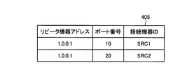
- the device list data 405 is data indicating a list of connected devices on the upstream side of the repeater device 400. As shown in FIG. 3, the device list data 405 is registered in association with the address of the repeater device 400, the port number of the port to which the connected device is connected, and the connected device ID for identifying the connected device. The Here, the device list data 405 can search for a record registered using a port number as a key.
- the device list data 405 is stored in a storage medium such as a hard disk drive (HDD) or a memory.
- HDD hard disk drive
- the function list management unit 404 transmits the model information to the device list data 405. That is, the port number of the port connected to the mobile terminal 200, the connected device ID of the mobile terminal 200, and the address of the repeater device 400 are added in association with each other. If already registered, it is updated when there is a change.
- the function list management unit 404 determines that the model information acquired from the upstream-side connected device by the determining unit 402 is “repeater device”, and the communication unit 401 determines another repeater that is the connected device.
- the device list data in the other repeater device is received from the device, the port number of the port to which the other repeater device is connected and its own address are added in association with the received device list information.
- the input switching unit 407 activates the port number specified by the input switching command.
- the digital television 100 of this embodiment includes an antenna 2, a tuner 3 for receiving digital broadcasting, a signal processing unit 4, a video processing unit 5, a display processing unit 6, and a display unit. 7, audio processing unit 8, speaker 9, control unit 10, communication line 11, RAM 12 (Random Access Memory), ROM 13 (Read Only Memory), operation unit 14, light receiving unit 15, input An output control unit 16 and a communication unit 17 are mainly provided.
- the antenna 2 receives digital broadcasts such as BS, CS, and terrestrial waves.
- the tuner 3 selects a viewing channel designated by the user.
- the signal processing unit 4 extracts and processes the signal demodulated by the tuner 3 and the signal input from the input / output control unit 16 as various digital signals.
- the signal processing unit 4 separates the input signal into a video signal and an audio signal, and outputs the video signal to the video processing unit 5 and the audio signal to the audio processing unit 8.
- the video processing unit 5 performs processing for adjusting the video signal input from the signal processing unit 4 to the correct screen size, processing for removing noise included in the video signal, and the like as image quality processing for improving the image quality of the video.
- the display processing unit 6 performs processing for displaying the video signal output from the video processing unit 5 on the display unit 7. Further, the display processing unit 6 further superimposes OSD (On-Screen Display) display such as character information on the video signal output from the video processing unit 5.
- OSD On-Screen Display
- the display unit 7 displays the video signal on the screen. Then, the user views the television image by viewing the screen of the display unit 7.
- the audio processing unit 8 performs acoustic processing and amplifies the audio signal.
- the speaker 9 outputs an audio signal as audio. The user listens to the television sound by listening to the sound from the speaker 9.
- the control unit 10 controls each unit of the digital television 100.
- the control unit 10 is a processing unit capable of sequence processing.
- the control unit 10 outputs a control signal to each unit of the digital television 100 by developing the program stored in the ROM 13 in the RAM 12 and sequentially executing the program. Central control of movement.
- the communication line 11 connects the tuner 3, the signal processing unit 4, the video processing unit 5, the display processing unit 6, the audio processing unit 8, and the control unit 10 to each other, and the control unit 10, the tuner 3, and the signal processing unit 4. Data is exchanged among the video processing unit 5, the display processing unit 6, and the audio processing unit 8.
- the communication line 11 may be IIC-BUS or the like.
- the RAM 12 and ROM 13 store various data, and these data are exchanged with the control unit 10.
- the operation unit 14 is a switch that receives a user operation instruction.
- the light receiving unit 15 receives a signal transmitted from the remote controller 40 that has received a user operation instruction.
- the user can operate the digital television 100 and each device connected to the digital television 100 by operating various buttons and keys of the remote controller 40.
- the communication unit 17 has a function of communicating with a server connected via a network such as the Internet, requests information from the server, and receives information transmitted from the server.
- the input / output control unit 16 is connected to the repeater device 400 and transmits / receives data to / from the repeater device 400.
- the input / output control unit 16 functions as a second transmission unit and a second reception unit.
- the input / output control unit 16 transmits an RCP command to the repeater device 400.
- the input / output control unit 16 receives device list data managed by the repeater device 400 from the repeater device 400 as a response.
- the input / output control unit 16 includes the port number corresponding to the device ID of the portable device 200 or other sink device desired to be accessed by the user and the address of the repeater device 400 in the device list data. Then, various RCP commands are transmitted to the repeater device 400.
- the communication unit 401 acquires model information from the connected device on the downstream side (downstream side) (step S11). Then, the determination unit 402 determines the content of the model information of the downstream side connected device acquired in step S11 (step S12).
- step S12 sink device
- the address determination unit 403 recognizes that the sink device is the downstream end of the MHL topology, and the repeater device 400 It is determined that the position in the MHL topology is the position immediately before the downstream end, and an address indicating the position upstream of the downstream end is determined (step S13).
- the address determination unit 403 sets “1.0.0 as an address indicating a position upstream from the downstream end. .1 ".
- the address determination method is not limited to this.
- step S12 when it is determined in step S12 that the model information is “repeater device” (step S12: repeater device), the communication unit 401 reads from the capability register of the other repeater device that is the connected device. The address of another repeater device is acquired (step S14). Then, the address determination unit 403 determines the address of its own repeater device 400 from the addresses of other repeater devices (step S15).
- the address determination unit 403 determines an address indicating one upstream position from the acquired position of another repeater device. For example, in the example in which the address of another repeater device is “1.0.0.1”, the address determination unit 403 uses “1.0.0.1” as an address indicating a position one upstream side from the downstream end. 0.2 ". However, the address determination method is not limited to this.
- steps S16 to S20 is repeatedly executed for all the connected devices connected to the upstream side (upstream side) of the repeater device 400.
- step S16 the communication unit 401 acquires model information from the connected device on the upstream side (upstream side) (step S16). Then, the determination unit 402 determines the content of the model information of the upstream side connected device acquired in step S16 (step S17).
- the device list management unit 404 recognizes that the source device is the upstream terminal of the MHL topology, and repeater device 400.
- the position in the MHL topology is determined to be a position immediately before the downstream end, and the port number of the port 408 to which the connection device (portable device 200) as the source device is connected to the device list data 405,
- the device ID of the source device and the address of the repeater device 400 are associated with each other, and a new record is added or an existing record with the same port number is updated (step S18). If the device list data 405 itself does not exist, the device list management unit 404 generates the device list data and then performs the registration.
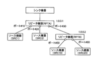
- FIG. 6 is a diagram illustrating an example of the MHL topology according to the first embodiment.
- a repeater device RPTA
- the source device SRC 1 is connected to the port of port number 10 of the repeater device (RPTA)
- the source device SRC2
- a repeater device RPTB
- the source device SRC10 is connected to the port of port number 50 of the repeater device (RPTB)
- the source device SRC20 is connected to the port of port number 60, respectively.
- the address of the repeater device (RPTA) is determined to be “1.0.0.1” and the address of the repeater device (RPTB) is determined to be “1.0.0.2”.
- the device list management unit 404 As a result of executing steps S17 and S18 in the repeater device (RPTA), the device list management unit 404 generates device list data shown in FIG. In the device list data 405 shown in FIG. 7, the source device (SRC1) is associated with the port number 10 and the source device (SRC2) is associated with the port number 20, together with the address of the repeater device (RPTA).
- step S ⁇ b> 17 repeater device
- the communication unit 401 receives the connection device, that is, another repeater device from the relevant device.
- Device list data stored in another repeater device is acquired (step S19).
- the device list management unit 404 adds the port number of the port connected to the other repeater device and the address of its own repeater device 400 in association with the device list data acquired in step S19 (step S20). .
- the device list management unit 404 will manage this device list data as its own device list data 405.
- the device list management unit 404 acquires the device list data of the other repeater devices acquired in step S19 and added or updated in step S20, and After own device list data 405 is merged, it is managed as own device list data 405.
- the repeater device (RPTB) is connected to the port of port number 30 of the repeater device (RPTA). It is assumed that the repeater device (RPTB) holds the device list data shown in FIG. As shown in FIG. 8, in the device list data of the repeater device (RPTB), the source device (SRC10) is associated with the port number 50 and the source device (SRC20) is associated with the port number 50 together with the address of the repeater device (RPTB). It has been.
- the communication unit 401 of the repeater device (RPTA) acquires the device list data illustrated in FIG. 8 from the repeater device (RPTB), and the device The list management unit 404 associates the device list data with the port number 30 of the port to which the repeater device (RPTB) is connected and the address “1.0.0.1” of its own repeater device (RPTA). to add. Then, the device list management unit 404 merges the device list data with the device list data shown in FIG. 7 already held in the repeater device (RPTA), and as a result, generates the device list data shown in FIG. To do.
- the input / output control unit 16 transmits a device list request command to the repeater device 400 (step S30).
- the communication unit 401 receives the device list request command, it transmits device list data 405 to the sink device as a response (step S31).
- the input / output control unit 16 receives the device list data 405, and the display processing unit 6 causes the user to select a desired source device to be accessed from the list of source devices registered in the device list data 405.
- a source device selection screen is displayed on the display unit 7. As shown in FIG. 11, a list of device IDs of source devices registered in the device list data 405 is displayed on the source device selection screen.
- the input / output control unit 16 of the digital television 100 receives the selection via the light receiving unit 15 (step S33). Then, the input / output control unit 16 transmits, to the repeater device 400, an input switching command specifying the port number corresponding to the device ID of the selected source device and the address of the repeater device in the device list data 405 (step S34). .
- the input switching unit 407 activates the port of the port number specified by the input switching command (step S35).
- the input / output control unit 16 of the digital television 100 transmits a desired RCP command to the repeater device 400 (step S36).
- the communication unit 401 when the communication unit 401 receives this RCP command, the received RCP command is transferred from the port activated in step S35 to the source device (mobile device 200) connected to the port ( Step S37). As described above, the digital television 100 can transmit the RCP command to a desired source device.
- the repeater device 400 acquires model information from each of the downstream-side connected device and all the upstream-side connected devices, determines its own address based on the model information, Device list data 405 that is a list of one or more connected devices on the downstream side is generated, and the device list data is transmitted to the digital television 100 that is a sink device. Then, the repeater device 400 activates the port having the port number designated by the sink device and transfers the RCP command received from the sink device from the activated port to the source device. For this reason, in the present embodiment, since the sink device can grasp and access all the source devices connected to the repeater device 400, the sink device can transmit one-to-many RCP commands from the source device. It becomes possible, and a plurality of source devices can be controlled smoothly.
- the repeater device determines its own address based on the model information of the connected device and includes this address.
- Device list data 405 is generated and transmitted to the sink device. For this reason, according to the present embodiment, on the sink device side, it is possible to easily grasp the repeater device and a plurality of source devices connected to the repeater device.
- the configurations of the repeater device 400 and the digital television 100 of the present embodiment are the same as those of the first embodiment.
- the device list data 405 of the present embodiment is the same as that of the first embodiment.
- the repeat device 400 detects and notifies the disconnection in the process of communication processing in which its own address is determined and the device list data 405 is registered.
- FIG. 13 is a flowchart illustrating a communication processing procedure performed by the repeater device according to the second embodiment. Since the processing up to step S50 is performed in the same manner as the processing from step S11 to S15 in the communication processing of the first embodiment, it is omitted in FIG.
- step S50 the communication unit 401 accesses the connected device on the upstream side (upstream side) and determines whether or not access is possible (step S50). If the access can be made (step S50: Yes), the process proceeds to step S16, and thereafter, the same processing as in the first embodiment is performed.
- step S50 when the communication unit 401 cannot access the connected device in step S50 (step S50: No), the device list management unit 404 displays the port number and repeater of the port to which the connected device that could not be connected is connected. A record including the address of the device 400 and the device ID of the connected device is deleted from the device list data 405 and updated (step S51).
- the communication unit 401 transmits the updated device list data 405 to the digital television 100 that is a sink device (step S52). If the device list data 405 has not yet been generated, the communication unit 401 displays the port number of the port connected to the connection device that could not be connected, the address of the repeater device 400, and the device ID of the connection device. It transmits to the digital television 100.
- the repeater device 400 may be configured to detect disconnection of the source device.
- FIG. 14 is a sequence diagram illustrating a communication processing procedure between the repeater device and the sink device according to the second embodiment.
- the processing from step S30 to S36 is the same as in the first embodiment.
- the communication unit 401 of the repeater device 400 receives the RPC command transmitted in step S36 and transmits the RCP command to the source device from the port having the port number specified by the RCP command (step S37), but the source device can be accessed. If not, the repeater device 400 determines that the source device is disconnected.
- the device list management unit 404 deletes the record including the port number of the port to which the source device that could not be connected, the address of the repeater device 400, and the device ID of the connected device is deleted from the device list data 405 and updated. (Step S61). Then, the communication unit 401 transmits the updated device list data 405 to the digital television 100 that is a sink device (step S62).
- the detection and the notification that the source device is disconnected are performed.
- the device can grasp the source device that is disconnected and cannot be accessed, the port number to which the source device is connected, and the address of the repeater device 400.
- the repeater device 400 deletes, from the device list data 405, a record including the port number of the port to which the source device that could not be connected, the address of the repeater device 400, and the device ID of the connected device.
- the updated device list data 405 is transmitted to the sink device. Regardless of the presence of the device list data 405, the port number of the port to which the connected device that could not be connected is connected, the address of the repeater device 400,
- the communication unit 401 may be configured to transmit the device ID of the connected device to the digital television 100.
- the present invention is not limited to the above-described embodiment as it is, and can be embodied by modifying the constituent elements without departing from the scope of the invention in the implementation stage.
- various inventions can be formed by appropriately combining a plurality of constituent elements disclosed in the embodiment. For example, some components may be deleted from all the components shown in the embodiment. Furthermore, the constituent elements over different embodiments may be appropriately combined.
Landscapes
- Engineering & Computer Science (AREA)
- Multimedia (AREA)
- Signal Processing (AREA)
- General Engineering & Computer Science (AREA)
- Two-Way Televisions, Distribution Of Moving Picture Or The Like (AREA)
Abstract
La présente invention, selon un mode de réalisation, concerne un système de communication comprenant : un appareil d'émission et un appareil relais connecté entre l'appareil d'émission et chacun de plusieurs appareils de réception. L'appareil relais comprend une première unité de réception, une unité de gestion de liste de dispositifs et une première unité d'émission. La première unité de réception reçoit, des plusieurs appareils de réception, leurs éléments d'informations respectifs de modèle. L'unité de gestion de liste de dispositifs génère, pour chacun de plusieurs éléments d'informations d'identification de port permettant d'identifier les ports respectifs auxquels sont connectés les appareils respectifs parmi les plusieurs appareils de réception, un élément d'information respectif de liste de dispositifs obtenu par association d'un élément d'information respectif d'identification de dispositif permettant d'identifier l'appareil respectif parmi les appareils de réception avec un élément d'information de position associé à la position de l'appareil relais. La première unité d'émission transmet les éléments d'informations de liste de dispositifs à l'appareil d'émission. L'appareil d'émission transmet, à l'appareil relais, une instruction qui désigne l'élément d'information d'identification de port correspondant, parmi les éléments d'informations de liste de dispositifs, à l'élément d'information d'identification de dispositif de l'appareil, parmi les appareils de réception, qui doit faire l'objet d'un accès et qui désigne également l'élément d'information de position de l'appareil relais.
Priority Applications (2)
| Application Number | Priority Date | Filing Date | Title |
|---|---|---|---|
| JP2013541108A JPWO2014207931A1 (ja) | 2013-06-28 | 2013-06-28 | 通信システム、方法および中継装置 |
| PCT/JP2013/067923 WO2014207931A1 (fr) | 2013-06-28 | 2013-06-28 | Système et procédé de communication |
Applications Claiming Priority (1)
| Application Number | Priority Date | Filing Date | Title |
|---|---|---|---|
| PCT/JP2013/067923 WO2014207931A1 (fr) | 2013-06-28 | 2013-06-28 | Système et procédé de communication |
Publications (1)
| Publication Number | Publication Date |
|---|---|
| WO2014207931A1 true WO2014207931A1 (fr) | 2014-12-31 |
Family
ID=52141322
Family Applications (1)
| Application Number | Title | Priority Date | Filing Date |
|---|---|---|---|
| PCT/JP2013/067923 Ceased WO2014207931A1 (fr) | 2013-06-28 | 2013-06-28 | Système et procédé de communication |
Country Status (2)
| Country | Link |
|---|---|
| JP (1) | JPWO2014207931A1 (fr) |
| WO (1) | WO2014207931A1 (fr) |
Citations (3)
| Publication number | Priority date | Publication date | Assignee | Title |
|---|---|---|---|---|
| JP2012138933A (ja) * | 2012-02-21 | 2012-07-19 | Toshiba Corp | 通信システム |
| JP2012204999A (ja) * | 2011-03-24 | 2012-10-22 | Panasonic Corp | 中継システム、中継装置および中継方法 |
| JP2013106117A (ja) * | 2011-11-11 | 2013-05-30 | Onkyo Corp | 中継装置、及びそのプログラム |
-
2013
- 2013-06-28 WO PCT/JP2013/067923 patent/WO2014207931A1/fr not_active Ceased
- 2013-06-28 JP JP2013541108A patent/JPWO2014207931A1/ja active Pending
Patent Citations (3)
| Publication number | Priority date | Publication date | Assignee | Title |
|---|---|---|---|---|
| JP2012204999A (ja) * | 2011-03-24 | 2012-10-22 | Panasonic Corp | 中継システム、中継装置および中継方法 |
| JP2013106117A (ja) * | 2011-11-11 | 2013-05-30 | Onkyo Corp | 中継装置、及びそのプログラム |
| JP2012138933A (ja) * | 2012-02-21 | 2012-07-19 | Toshiba Corp | 通信システム |
Also Published As
| Publication number | Publication date |
|---|---|
| JPWO2014207931A1 (ja) | 2017-02-23 |
Similar Documents
| Publication | Publication Date | Title |
|---|---|---|
| US8395706B2 (en) | Information processing system, display device, output device, information processing device, identification information acquisition method and identification information supply method | |
| EP3005649B1 (fr) | Systèmes, procédés et supports pour présenter un contenu multimédia | |
| US8711285B2 (en) | Output device, source apparatus, television set, system, output method, program, and recording medium | |
| KR102266194B1 (ko) | 데이터를 송수신하기 위한 멀티미디어 장치들간 출력 장치 공유 방법 및 시스템 | |
| EP3096531A1 (fr) | Procédé, appareil et système de partage d'un seul écran | |
| US9357215B2 (en) | Audio output distribution | |
| US9749373B2 (en) | System and method for improved content streaming | |
| WO2015139547A1 (fr) | Procédé, dispositif et système d'établissement de scénario d'application | |
| WO2018096849A1 (fr) | Dispositif de traitement d'informations, procédé de traitement d'informations et programme | |
| JP2013143581A (ja) | 電子機器、端末、プログラムおよび機器操作制御方法 | |
| JP2009200788A (ja) | 受信装置 | |
| KR101339835B1 (ko) | 이동 단말의 실시간 화면 재생기, 그 시스템 및 화면 재생 방법 | |
| CN103002226B (zh) | 一种播放设备切换方法及装置 | |
| US20140258464A1 (en) | System and method for electronic device control | |
| JP2014175736A (ja) | 中継装置および中継方法 | |
| KR20140029049A (ko) | 디스플레이 장치 및 이를 이용한 입력 신호 처리 방법 | |
| KR20120038116A (ko) | 전자기기, 제어장치 및 그 제어방법 | |
| JP6271169B2 (ja) | 番組関連プログラム | |
| WO2014207931A1 (fr) | Système et procédé de communication | |
| US20150019626A1 (en) | Server device, client machine, and content playback program | |
| JP2015103237A (ja) | 言語情報処理システム | |
| JP5752550B2 (ja) | サービス提供システム、端末装置、および、制御プログラム | |
| CN105913626A (zh) | 一种实现从源端显示屏到目的端显示屏的镜像功能的设备 | |
| JP6172761B2 (ja) | 情報通知装置、情報通知方法及び情報通知プログラム | |
| CN105451089A (zh) | 多媒体处理装置与多媒体通信系统 |
Legal Events
| Date | Code | Title | Description |
|---|---|---|---|
| ENP | Entry into the national phase |
Ref document number: 2013541108 Country of ref document: JP Kind code of ref document: A |
|
| 121 | Ep: the epo has been informed by wipo that ep was designated in this application |
Ref document number: 13888203 Country of ref document: EP Kind code of ref document: A1 |
|
| NENP | Non-entry into the national phase |
Ref country code: DE |
|
| 122 | Ep: pct application non-entry in european phase |
Ref document number: 13888203 Country of ref document: EP Kind code of ref document: A1 |