WO2015012182A1 - Dispositif de commande et véhicule assisté par une énergie électrique - Google Patents
Dispositif de commande et véhicule assisté par une énergie électrique Download PDFInfo
- Publication number
- WO2015012182A1 WO2015012182A1 PCT/JP2014/068984 JP2014068984W WO2015012182A1 WO 2015012182 A1 WO2015012182 A1 WO 2015012182A1 JP 2014068984 W JP2014068984 W JP 2014068984W WO 2015012182 A1 WO2015012182 A1 WO 2015012182A1
- Authority
- WO
- WIPO (PCT)
- Prior art keywords
- pedal
- speed
- unit
- motor
- control device
- Prior art date
- Legal status (The legal status is an assumption and is not a legal conclusion. Google has not performed a legal analysis and makes no representation as to the accuracy of the status listed.)
- Ceased
Links
Images

Classifications
-
- B—PERFORMING OPERATIONS; TRANSPORTING
- B62—LAND VEHICLES FOR TRAVELLING OTHERWISE THAN ON RAILS
- B62M—RIDER PROPULSION OF WHEELED VEHICLES OR SLEDGES; POWERED PROPULSION OF SLEDGES OR SINGLE-TRACK CYCLES; TRANSMISSIONS SPECIALLY ADAPTED FOR SUCH VEHICLES
- B62M6/00—Rider propulsion of wheeled vehicles with additional source of power, e.g. combustion engine or electric motor
- B62M6/40—Rider propelled cycles with auxiliary electric motor
- B62M6/45—Control or actuating devices therefor
Definitions
- the present invention relates to a control technique in an electric assist vehicle.
- Control of an electric motor such as an electric assist bicycle is performed based on a signal from a torque sensor, a vehicle speed sensor, a motor current sensor, or the like, according to the purpose.
- the drive control is performed from various viewpoints such as safety, legal compliance, assist feeling, startability, and the like, but it is assumed that the sensor always outputs a correct value in order to perform appropriate drive control.
- the sensors may output an offset value other than zero even when there is no input. Since this offset value is caused by component variations, aging deterioration, and temperature change, calibration is performed at an appropriate timing. *
- an electric motor such as an electric assist bicycle is required to extend the travel distance as much as possible by one charge. For this reason, in the case of a minute input torque, it is effective to perform control without motor driving. However, if the criterion for the minute input torque is not set appropriately, the motor drive cannot be switched on and off properly. In addition, once the motor has been driven, there is a conventional technique that turns off the motor drive when a small amount of input torque has elapsed for a certain period of time, but the motor drive is different from the driver's drive intention. Will be turned off.
- the objective of this invention is providing the technique for enabling it to grasp
- the control device determines whether or not (A) the motor-driven wheel speed and the pedal rotation conversion speed obtained from the pedal rotation satisfy a predetermined condition indicating that the vehicle is coasting. And an instruction unit that enables execution of processing according to the state of coasting when it is determined that the motor-driven wheel speed and the pedal rotation conversion speed satisfy the above conditions. And have. *
- the above-described conditions are (a) the first condition that the pedal rotation conversion speed is slower than the motor driving wheel speed, and (b) the difference between the motor driving wheel speed and the pedal rotation conversion speed is the first threshold value.
- the third threshold value may be set according to the first threshold value or the second threshold value. For example, when the second threshold value is small, a setting may be made such that the third threshold value is large.
- the first threshold value or the second threshold value may be set according to the motor rotation speed.
- the problem of sensor value accuracy is taken into account.
- the process described above may be a process of calibrating the offset value of the pedal input torque. Further, the above-described process is a process of setting the difference to 0 when the difference between the pedal input torque and the offset value of the pedal input torque is a positive value in a state where the pedal rotation is detected. Or it may be a process which stops a motor drive. In performing such processing, if there is a state of inertia running, the processing can be appropriately performed. *
- the program is stored in a computer-readable storage medium or storage device such as a flexible disk, an optical disk such as a CD-ROM, a magneto-optical disk, a semiconductor memory (for example, ROM), or a hard disk.
- a storage device such as a RAM (Random Access Memory).
- FIG. 1 is a view showing an appearance of a motor-equipped bicycle.
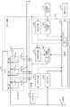
- FIG. 2 is a functional block diagram of the motor drive controller.
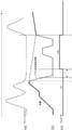
- FIG. 3 is a diagram showing an outline of the embodiment.
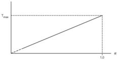
- FIG. 4 is a schematic diagram showing the relationship between the coefficient ⁇ and the grace period T.
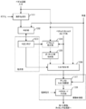
- FIG. 5 is a functional block diagram of the calculation unit.
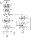
- FIG. 6 is a diagram illustrating a processing flow of the determination unit.
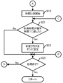
- FIG. 7 is a diagram illustrating a processing flow of the determination unit.
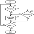
- FIG. 8 is a diagram illustrating a processing flow of the offset calibration unit.
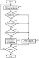
- FIG. 9 is a diagram illustrating a processing flow of the torque calibration unit.
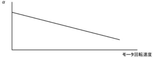
- FIG. 10 is a diagram showing the relationship between the coefficient ⁇ and the motor rotation speed.
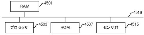
- FIG. 11 is a functional block diagram when implemented by a microprocessor.
- FIG. 1 is an external view showing an example of a motor-equipped bicycle that is an electrically assisted vehicle according to the present embodiment.
- This motorized bicycle 1 is equipped with a motor drive device.
- the motor drive device includes a secondary battery 101, a motor drive controller 102, a torque sensor 103, a pedal rotation sensor 104, a motor 105, and an operation panel 106. *
- the secondary battery 101 is, for example, a lithium ion secondary battery having a maximum supply voltage (voltage at full charge) of 24 V, but may be another type of battery, such as a lithium ion polymer secondary battery, a nickel hydride storage battery, or the like. good. *
- the torque sensor 103 is provided on a wheel attached to the crankshaft, detects the pedaling force of the pedal by the driver, and outputs the detection result to the motor drive controller 102.
- the pedal rotation sensor 104 is provided on a wheel attached to the crankshaft, and outputs a signal corresponding to the rotation to the motor drive controller 102.
- the motor 105 is, for example, a well-known three-phase DC brushless motor, and is mounted on the front wheel of the motorized bicycle 1, for example.
- the motor 105 rotates the front wheel, and the rotor is connected to the front wheel so that the rotor rotates in accordance with the rotation of the front wheel.
- the motor 105 includes a rotation sensor such as a Hall element, and outputs rotor rotation information (that is, a Hall signal) to the motor drive controller 102.
- a rotation sensor such as a Hall element
- the operation panel 106 receives, for example, an instruction input regarding the presence / absence of assist from the user, and outputs the instruction input to the motor drive controller 102.
- the operation panel 106 outputs a signal representing a transmission gear ratio (also referred to as a gear ratio) to the motor drive controller 102.
- a transmission gear ratio also referred to as a gear ratio
- the motor drive controller 102 includes a controller 1020 and an FET (Field Effect Transistor) bridge 1030.
- the FET bridge 1030 includes a high side FET (S uh ) and a low side FET (S ul ) that perform switching for the U phase of the motor 105, and a high side FET (S vh ) that performs switching for the V phase of the motor 105, and It includes a low-side FET (S vl ), a high-side FET (S wh ) and a low-side FET (S wl ) that perform switching for the W phase of the motor 105.
- This FET bridge 1030 constitutes a part of a complementary switching amplifier.
- the controller 1020 includes a calculation unit 1021, a pedal rotation input unit 1022, a vehicle speed input unit 1024, a variable delay circuit 1025, a motor drive timing generation unit 1026, a torque input unit 1027, and an AD input unit 1029.
- the calculation unit 1021 is input from the operation panel 106 (for example, gear ratio, on / off, etc.), input from the vehicle speed input unit 1024, input from the pedal rotation input unit 1022, input from the torque input unit 1027, AD input unit The operation described below is performed using the input from 1029. After that, output is made to the motor drive timing generation unit 1026 and the variable delay circuit 1025.
- the calculation unit 1021 includes a memory 10211, and the memory 10211 stores various data used for calculation, data being processed, and the like. Further, the calculation unit 1021 may be realized by executing a program by a processor. In this case, the program may be recorded in the memory 10211.
- the vehicle speed input unit 1024 calculates the current vehicle speed (also referred to as motor drive wheel speed) from the hall signal output by the motor 105 and outputs the calculated vehicle speed to the calculation unit 1021.
- the pedal rotation input unit 1022 digitizes a signal representing the pedal rotation phase angle and the like from the pedal rotation sensor 104 and outputs the digitized signal to the calculation unit 1021.
- the torque input unit 1027 digitizes a signal corresponding to the pedaling force from the torque sensor 103 and outputs the digitized signal to the calculation unit 1021.
- An AD (Analog-Digital) input unit 1029 digitizes the output voltage from the secondary battery 101 and outputs the digitized voltage to the arithmetic unit 1021. Further, the memory 10211 may be provided separately from the calculation unit 1021. *
- the calculation unit 1021 outputs an advance value to the variable delay circuit 1025 as a calculation result.
- the variable delay circuit 1025 adjusts the phase of the Hall signal based on the advance value received from the calculation unit 1021 and outputs the adjusted signal to the motor drive timing generation unit 1026.
- the calculation unit 1021 outputs, for example, a PWM (Pulse Width Modulation) code corresponding to the PWM duty ratio to the motor drive timing generation unit 1026 as a calculation result.
- the motor drive timing generation unit 1026 generates and outputs a switching signal for each FET included in the FET bridge 1030 based on the adjusted Hall signal from the variable delay circuit 1025 and the PWM code from the calculation unit 1021.
- the pedal input torque is removed when the pedal input torque is detected despite the fact that the pedal input torque must be zero due to the calibration of the offset value of the pedal input torque or noise.
- the timing of inertia running is used as the timing for stopping the motor drive.
- the torque sensor 103 should not originally detect the pedal input torque. Therefore, such a state is suitable for calibrating the offset value of the pedal input torque.
- the fact that the pedal input torque is detected during coasting is not caused by the driver's intentional input, but is caused by noise or other problems. It is preferable that the input torque is canceled or the motor drive corresponding to the pedal input torque is not performed.
- the vehicle speed gradually increases as shown in (b) in the first half part where the pedal input torque substantially continues.
- time t1 the vehicle speed and the pedal rotation conversion speed increase in a form that approximately matches, but when the pedal input torque is not input, the vehicle speed gradually decreases, but the pedal rotation is suppressed. Therefore, the pedal rotation conversion speed decreases rapidly.
- time t2 a relationship of pedal rotation conversion speed ⁇ vehicle speed ⁇ ⁇ (a coefficient of 1 or less, where approximately 0.5) is established. If this inequality is modified, the pedal rotation conversion speed / vehicle speed ⁇ . *
- ⁇ and the delay time T are set as margins for reliably detecting that the vehicle is coasting in consideration of sensor errors and gear ratio errors. If ⁇ is reduced, the grace period T may be shortened. On the other hand, if ⁇ is increased, it is preferable to increase the grace period T. Therefore, as an example, a relationship between ⁇ and a delay time T as shown in FIG. 4 is assumed. In FIG. 4, the horizontal axis represents ⁇ , and the vertical axis represents the grace time T. Thus, the grace time T is set shorter as ⁇ approaches zero, and when ⁇ becomes 1, the grace time T becomes the predetermined maximum value Tmax. If ⁇ is sufficiently small, the grace period T may be set to zero. In addition, when an accurate gear ratio can be acquired, when the measured value of the sensor has a certain level of reliability, the condition of pedal rotation conversion speed ⁇ vehicle speed may be used. *
- FIG. 5 shows a functional block diagram of the calculation unit 1021 that performs such inertia running determination processing, pedal input torque offset value calibration processing, erroneous detection pedal input torque cancellation processing, and the like.
- the calculation unit 1021 includes a conversion processing unit 1201, a determination unit 1202, a determination flag 1203, an offset calibration unit 1204, an offset value storage unit 1205, a torque calibration unit 1206, an assist torque calculation unit 1207, and a PWM code generation. Part 1208.
- the determination flag 1203 functions as an instruction unit, and the assist torque calculation unit 1207 and the PWM code generation unit 1208 operate as a motor drive control unit. *
- the conversion processing unit 1201 calculates the pedal rotation speed from the pedal rotation input from the pedal rotation input unit 1022 and calculates the pedal rotation conversion speed by multiplying the pedal rotation speed by the gear ratio.
- the determination unit 1202 determines whether or not the vehicle speed and the pedal rotation conversion speed satisfy a predetermined condition indicating that the vehicle is coasting, and if it is determined that the vehicle is coasting, the determination flag 1203 is turned on. Set. On the other hand, when it is determined that the vehicle is in the inertia running state, the determination unit 1202 sets the determination flag 1203 to OFF.
- the determination flag 1203 is an example of implementation, and the instruction unit may be configured by adopting another circuit configuration that instructs the determination result of the determination unit 1202 to the offset calibration unit 1204 or the torque calibration unit 1206. good. *
- the offset calibration unit 1204 executes processing for calibrating the offset value of the pedal input torque based on the determination flag 1203 and the pedal rotation input, and stores the offset value after calibration in the offset value storage unit 1205.
- the torque calibration unit 1206 performs calibration of pedal input torque, removal processing of erroneously detected pedal input torque, and the like using the offset value stored in the offset value storage unit 1205 based on the determination flag 1203 and the pedal rotation input. .
- the torque calibration unit 1206 may stop the motor drive if the condition is satisfied.
- the assist torque calculation unit 1207 performs a predetermined calculation based on the pedal input torque (which may be zero) from the torque calibration unit 1206 and the vehicle speed from the vehicle speed input unit 1024. Subsequently, a duty code related to the PWM duty ratio is output to the PWM code generation unit 1208.
- the calculation of the assist torque calculation unit 1207 is a calculation described in detail in, for example, the pamphlet of International Publication No. 2012/086458. Briefly, the pedal input torque is converted into a first duty code corresponding to the duty ratio according to a predetermined rule. The vehicle speed is converted into a second duty code corresponding to the duty ratio according to a predetermined rule. By adding the first and second duty codes, a duty code to be output to the PWM code generation unit 1208 is calculated. *
- the assist torque calculation unit 1207 outputs an instruction to stop the motor drive to the PWM code generation unit 1208 in response to a stop instruction from the torque calibration unit 1206.
- the PWM code generation unit 1208 receives an instruction to stop the motor drive from the assist torque calculation unit 1207
- the PWM code generation unit 1208 outputs a signal for stopping the motor to the motor drive timing generation unit 1026 and the like.
- the assist torque calculation unit 1207 may directly output an instruction to stop the motor.
- the conversion processing unit 1201 calculates the pedal rotation speed from the pedal rotation input from the pedal rotation input unit 1022, and further multiplies the pedal rotation speed by, for example, the gear ratio input from the operation panel 106 or the like.
- the speed is calculated (FIG. 6: step S1).
- the determination unit 1202 calculates the reference speed by multiplying the vehicle speed from the vehicle speed input unit 1024 by a coefficient ⁇ , for example (step S3).
- the reference speed may be calculated in the form of vehicle speed - ⁇ instead of vehicle speed ⁇ ⁇ . Since the condition of pedal rotation conversion speed ⁇ vehicle speed ⁇ is satisfied, it is modified such that ⁇ ⁇ vehicle speed ⁇ pedal rotation conversion speed. *
- the determination unit 1202 determines whether the determination flag 1203 is turned on (step S5). Initially, it is assumed that the determination flag 1203 and the grace time flag which is an internal flag are set to off. *
- step S7 determines whether or not the grace time flag is on (step S9). If the grace time flag is already turned on, the processing shifts to the processing in FIG. *
- the determination unit 1202 sets the grace time flag on (step S11). Then, the processing shifts to the processing in FIG. *
- step S5 Yes route
- the determination unit 1202 determines whether the pedal rotation conversion speed is equal to or higher than the vehicle speed (step S13). If this condition is not satisfied, the processing shifts to the processing in FIG. On the other hand, when this condition is satisfied (time t4 in FIG. 3), the determination unit 1202 sets the determination flag 1203 to off (step S15), and further sets the grace period flag to off (step S17). . Then, the processing shifts to the processing in FIG. *
- the determination unit 1202 starts time measurement (step S ⁇ b> 19). Then, the determination unit 1202 determines whether the measurement time has reached a grace period T (corresponding to a threshold value) (step S21). If the measurement time has not reached the grace time T, the process proceeds to step S25. On the other hand, when the measurement time reaches the grace time T, the determination unit 1202 sets the determination flag 1203 to ON (step S23). *
- the determination unit 1202 determines whether or not a process end is instructed from the operation panel 106 or the like (step S25). If the end of the process is not instructed, the process returns to step S1 in FIG. On the other hand, when the end of the process is instructed, the process ends. *
- the determination flag 1203 is set to be on during inertial running, and the determination flag 1203 is set to be off when the vehicle is out of inertial running.
- the offset calibration unit 1204 determines whether the pedal is rotating from the pedal rotation input from the pedal rotation input unit 1022 (FIG. 8: step S31). If the pedal is not rotating, the process proceeds to step S35. *
- the offset calibration unit 1204 determines whether the determination flag 1203 is on (step S33). If the determination flag 1203 is on, the offset calibration unit 1204 executes an offset calibration process, and stores the offset value after calibration in the offset value storage unit 1205 (step S35). As described above, there are various methods for the offset calibration process, and any method may be used, and therefore, detailed description thereof is omitted here. On the other hand, if the determination flag 1203 is off, the process proceeds to step S37. *
- the offset calibration unit 1204 determines whether the process end is instructed (step S37). If the end of the process is not instructed, the process returns to step S31. On the other hand, when the end of the process is instructed, the process ends. *
- the offset calibration process is performed when the pedal rotation is not detected and when the determination flag 1203 is set to ON. That is, even during traveling, the offset calibration process can be performed at a timing when the pedal input torque is essentially zero.
- the torque calibration unit 1206 calculates the pedal input torque after calibration by subtracting the offset value stored in the offset value storage unit 1205 from the pedal input torque (sensor value) (step S41). *
- the torque calibration unit 1206 determines whether or not the post-calibration pedal input torque is a positive value (step S43). If the pedal input torque after calibration is less than or equal to zero, the torque calibration unit 1206 clears the pedal input torque to zero and outputs it to the assist torque calculation unit 1207 or drives the motor with respect to the assist torque calculation unit 1203 and the like. An instruction is output so as to stop (step S51). When the pedal input torque is cleared to zero and output to the assist torque calculation unit 1207, the assist torque calculation unit 1207 performs a predetermined calculation based on the vehicle speed, for example, assuming that the pedal input torque is zero. The duty code related to the duty ratio is output to the PWM code generation unit 1208.
- the PWM code generation unit 1208 generates a PWM code by multiplying the duty code by the battery voltage / reference voltage (for example, 24 V) from the AD input unit 1029 and outputs the PWM code to the motor drive timing generation unit 1026. In this way, the motor drive is controlled. Then, the process proceeds to step S53. *
- the torque calibration unit 1206 determines whether or not the pedal is rotating from the pedal rotation input (step S45). If the pedal is not rotating, the pedal input torque after calibration is not appropriate, and the process proceeds to step S51. *
- step S47 determines whether or not the determination flag 1203 is off. If the determination flag 1203 is on, the vehicle is coasting and the process proceeds to step S51. *
- the assist torque calculation unit 1207 performs a predetermined calculation based on the pedal input torque and the vehicle speed after calibration from the torque calibration unit 1206, and outputs a duty code related to the PWM duty ratio to the PWM code generation unit 1208. Output. Further, the PWM code generation unit 1208 generates a PWM code by multiplying the duty code by the battery voltage / reference voltage (for example, 24 V) from the AD input unit 1029 and outputs the PWM code to the motor drive timing generation unit 1026. In this way, motor drive is controlled (step S49). *
- the torque calibration unit 1206 determines whether an instruction to end the process is given (step S53). If the end of the process is not instructed, the process returns to step S41. On the other hand, when the end of the process is instructed, the process ends. *
- the present invention is not limited to this.
- the motor rotation speed is low, the data input from the sensor also varies widely, and the margin should be increased. If the motor rotation speed is high, the data input from the sensor becomes stable and accurate. May be set according to the motor rotation speed. In the example of FIG. 10, ⁇ is set larger as the motor rotation speed is slower, and ⁇ is set smaller as the motor rotation speed is faster. *
- motor drive controller 102 may be realized by a dedicated circuit, or the function as described above may be realized by a microprocessor executing a program.
- a RAM (Random Access Memory) 4501, a processor 4503, a ROM (Read Only Memory) 4507, and a sensor group 4515 are connected by a bus 4519.
- a program for executing the processing in this embodiment and an operating system (OS: Operating System) when present are stored in the ROM 4507, and when executed by the processor 4503, the ROM 4507 to the RAM 4501. Is read out.
- OS Operating System
- the ROM 4507 records threshold values and other parameters, and such parameters are also read.
- the processor 4503 controls the sensor group 4515 described above to acquire a measurement value. Further, data in the middle of processing is stored in the RAM 4501.
- the processor 4503 may include a ROM 4507, and may further include a RAM 4501.
- a control program for performing the above-described processing may be stored and distributed on a computer-readable removable disk and written to the ROM 4507 by a ROM writer.
- Such a computer apparatus has various functions as described above by organically cooperating hardware such as the processor 4503, RAM 4501, and ROM 4507 described above and a program (or OS in some cases). Realize.
- Conversion processing unit 1202 Determination unit 1203 Determination flag 1204 Offset calibration unit 1205 Offset value storage unit 1206 Torque calibration unit 1207 Assist torque calculation unit 1208 PWM code generation unit
Landscapes
- Engineering & Computer Science (AREA)
- Chemical & Material Sciences (AREA)
- Combustion & Propulsion (AREA)
- Transportation (AREA)
- Mechanical Engineering (AREA)
- Electric Propulsion And Braking For Vehicles (AREA)
Abstract
L'invention vise à permettre une estimation correcte d'une temporisation selon laquelle un processus associé à l'entraînement d'un moteur d'une bicyclette assistée par une énergie électrique peut être exécuté. A cet effet, l'invention porte sur un dispositif de commande, lequel dispositif a : (A) une unité de détermination qui détermine si oui ou non une vitesse de roue entraînée par un moteur et une vitesse équivalente de pédalage, qui est calculée à partir d'une rotation de pédales, satisfont à une condition prédéterminée indiquant que la bicyclette est dans un état de marche sur l'erre ; et (B) une unité d'instruction, qui, quand il est déterminé que la vitesse de roue entraînée par un moteur et la vitesse équivalente de pédalage satisfont à la condition, permet un processus approprié pour l'exécution de l'état de marche sur l'erre.
Applications Claiming Priority (2)
| Application Number | Priority Date | Filing Date | Title |
|---|---|---|---|
| JP2013151248A JP6198498B2 (ja) | 2013-07-22 | 2013-07-22 | 制御装置及び電動アシスト車 |
| JP2013-151248 | 2013-07-22 |
Publications (1)
| Publication Number | Publication Date |
|---|---|
| WO2015012182A1 true WO2015012182A1 (fr) | 2015-01-29 |
Family
ID=52393224
Family Applications (1)
| Application Number | Title | Priority Date | Filing Date |
|---|---|---|---|
| PCT/JP2014/068984 Ceased WO2015012182A1 (fr) | 2013-07-22 | 2014-07-17 | Dispositif de commande et véhicule assisté par une énergie électrique |
Country Status (2)
| Country | Link |
|---|---|
| JP (1) | JP6198498B2 (fr) |
| WO (1) | WO2015012182A1 (fr) |
Families Citing this family (3)
| Publication number | Priority date | Publication date | Assignee | Title |
|---|---|---|---|---|
| JP7142265B2 (ja) * | 2018-09-10 | 2022-09-27 | パナソニックIpマネジメント株式会社 | 電動自転車及び電動自転車の制御方法 |
| JP2025069558A (ja) * | 2023-10-18 | 2025-05-01 | ミネベアミツミ株式会社 | 制御装置、電動アシスト自転車およびアシスト制御方法 |
| JP2025111337A (ja) * | 2024-01-17 | 2025-07-30 | ミネベアミツミ株式会社 | 電動アシスト自転車 |
Citations (3)
| Publication number | Priority date | Publication date | Assignee | Title |
|---|---|---|---|---|
| JPH08230752A (ja) * | 1995-02-28 | 1996-09-10 | Sanyo Electric Co Ltd | 電動自転車 |
| JPH1059264A (ja) * | 1996-08-27 | 1998-03-03 | Mitsubishi Heavy Ind Ltd | 補助電動モータ付乗物及びその踏力検出値補正方法 |
| WO2012105198A1 (fr) * | 2011-01-31 | 2012-08-09 | 三洋電機株式会社 | Vélo électrique |
Family Cites Families (1)
| Publication number | Priority date | Publication date | Assignee | Title |
|---|---|---|---|---|
| JP3736157B2 (ja) * | 1998-12-04 | 2006-01-18 | スズキ株式会社 | 電動補助自転車 |
-
2013
- 2013-07-22 JP JP2013151248A patent/JP6198498B2/ja active Active
-
2014
- 2014-07-17 WO PCT/JP2014/068984 patent/WO2015012182A1/fr not_active Ceased
Patent Citations (3)
| Publication number | Priority date | Publication date | Assignee | Title |
|---|---|---|---|---|
| JPH08230752A (ja) * | 1995-02-28 | 1996-09-10 | Sanyo Electric Co Ltd | 電動自転車 |
| JPH1059264A (ja) * | 1996-08-27 | 1998-03-03 | Mitsubishi Heavy Ind Ltd | 補助電動モータ付乗物及びその踏力検出値補正方法 |
| WO2012105198A1 (fr) * | 2011-01-31 | 2012-08-09 | 三洋電機株式会社 | Vélo électrique |
Also Published As
| Publication number | Publication date |
|---|---|
| JP2015020642A (ja) | 2015-02-02 |
| JP6198498B2 (ja) | 2017-09-20 |
Similar Documents
| Publication | Publication Date | Title |
|---|---|---|
| US20160202710A1 (en) | Motor driving control apparatus and electrically assisted vehicle | |
| TWI531506B (zh) | Motor drive control device | |
| US9906174B2 (en) | Power steering device and control device for power steering device | |
| JP5965517B2 (ja) | モータ制御装置及び制御装置 | |
| US9136780B2 (en) | Controller for driving a motor and electric power-assisted vehicle | |
| US10099558B2 (en) | Motor driving apparatus | |
| JP6411714B2 (ja) | モータ駆動制御装置及び電動アシスト車 | |
| EP3459782B1 (fr) | Appareil de commande d'entraînement de moteur et véhicule à assistance par moteur | |
| JP6198498B2 (ja) | 制御装置及び電動アシスト車 | |
| JP5785527B2 (ja) | モータ駆動制御装置及び電動アシスト車 | |
| JP2002127922A (ja) | 電動パワーステアリング装置 | |
| JP6381321B2 (ja) | 制御装置及び電動アシスト車 | |
| JP2012046049A (ja) | 操舵装置 | |
| JP2009131069A (ja) | モータ制御装置 | |
| TWI646014B (zh) | Control device and electric auxiliary vehicle | |
| JP7234055B2 (ja) | 電流方向判定装置 | |
| JP2001128482A (ja) | 直流無整流子モータの異常検出方法および装置 | |
| JP2001128479A (ja) | 直流無整流子モータの駆動制御方法および装置 | |
| JP4270151B2 (ja) | モータ制御装置及びこの装置を搭載する車両の制御装置 | |
| TWI619638B (zh) | Motor drive control device and electric auxiliary vehicle | |
| JP2762370B2 (ja) | 電気式動力舵取装置の制御方法 | |
| JP3376978B2 (ja) | 車両の電動パワーステアリング装置 | |
| TW202517520A (zh) | 控制裝置、電動輔助自行車及輔助控制方法 | |
| JP2008254632A5 (fr) | ||
| JP2001119803A (ja) | 小型電動車両のモータ駆動制御方法および装置 |
Legal Events
| Date | Code | Title | Description |
|---|---|---|---|
| 121 | Ep: the epo has been informed by wipo that ep was designated in this application |
Ref document number: 14830067 Country of ref document: EP Kind code of ref document: A1 |
|
| NENP | Non-entry into the national phase |
Ref country code: DE |
|
| 122 | Ep: pct application non-entry in european phase |
Ref document number: 14830067 Country of ref document: EP Kind code of ref document: A1 |