WO2015052814A1 - 靴底 - Google Patents
靴底 Download PDFInfo
- Publication number
- WO2015052814A1 WO2015052814A1 PCT/JP2013/077631 JP2013077631W WO2015052814A1 WO 2015052814 A1 WO2015052814 A1 WO 2015052814A1 JP 2013077631 W JP2013077631 W JP 2013077631W WO 2015052814 A1 WO2015052814 A1 WO 2015052814A1
- Authority
- WO
- WIPO (PCT)
- Prior art keywords
- cleats
- midsole
- outsole
- base
- shoe sole
- Prior art date
- Legal status (The legal status is an assumption and is not a legal conclusion. Google has not performed a legal analysis and makes no representation as to the accuracy of the status listed.)
- Ceased
Links
Images


Classifications
-
- A—HUMAN NECESSITIES
- A43—FOOTWEAR
- A43B—CHARACTERISTIC FEATURES OF FOOTWEAR; PARTS OF FOOTWEAR
- A43B13/00—Soles; Sole-and-heel integral units
- A43B13/14—Soles; Sole-and-heel integral units characterised by the constructive form
- A43B13/22—Soles made slip-preventing or wear-resisting, e.g. by impregnation or spreading a wear-resisting layer
- A43B13/223—Profiled soles
-
- A—HUMAN NECESSITIES
- A43—FOOTWEAR
- A43B—CHARACTERISTIC FEATURES OF FOOTWEAR; PARTS OF FOOTWEAR
- A43B13/00—Soles; Sole-and-heel integral units
- A43B13/02—Soles; Sole-and-heel integral units characterised by the material
- A43B13/04—Plastics, rubber or vulcanised fibre
-
- A—HUMAN NECESSITIES
- A43—FOOTWEAR
- A43B—CHARACTERISTIC FEATURES OF FOOTWEAR; PARTS OF FOOTWEAR
- A43B13/00—Soles; Sole-and-heel integral units
- A43B13/02—Soles; Sole-and-heel integral units characterised by the material
- A43B13/12—Soles with several layers of different materials
-
- A—HUMAN NECESSITIES
- A43—FOOTWEAR
- A43B—CHARACTERISTIC FEATURES OF FOOTWEAR; PARTS OF FOOTWEAR
- A43B13/00—Soles; Sole-and-heel integral units
- A43B13/02—Soles; Sole-and-heel integral units characterised by the material
- A43B13/12—Soles with several layers of different materials
- A43B13/125—Soles with several layers of different materials characterised by the midsole or middle layer
-
- A—HUMAN NECESSITIES
- A43—FOOTWEAR
- A43B—CHARACTERISTIC FEATURES OF FOOTWEAR; PARTS OF FOOTWEAR
- A43B13/00—Soles; Sole-and-heel integral units
- A43B13/14—Soles; Sole-and-heel integral units characterised by the constructive form
- A43B13/141—Soles; Sole-and-heel integral units characterised by the constructive form with a part of the sole being flexible, e.g. permitting articulation or torsion
-
- A—HUMAN NECESSITIES
- A43—FOOTWEAR
- A43B—CHARACTERISTIC FEATURES OF FOOTWEAR; PARTS OF FOOTWEAR
- A43B13/00—Soles; Sole-and-heel integral units
- A43B13/14—Soles; Sole-and-heel integral units characterised by the constructive form
- A43B13/18—Resilient soles
- A43B13/181—Resiliency achieved by the structure of the sole
-
- A—HUMAN NECESSITIES
- A43—FOOTWEAR
- A43B—CHARACTERISTIC FEATURES OF FOOTWEAR; PARTS OF FOOTWEAR
- A43B13/00—Soles; Sole-and-heel integral units
- A43B13/14—Soles; Sole-and-heel integral units characterised by the constructive form
- A43B13/18—Resilient soles
- A43B13/187—Resiliency achieved by the features of the material, e.g. foam, non liquid materials
-
- A—HUMAN NECESSITIES
- A43—FOOTWEAR
- A43B—CHARACTERISTIC FEATURES OF FOOTWEAR; PARTS OF FOOTWEAR
- A43B13/00—Soles; Sole-and-heel integral units
- A43B13/14—Soles; Sole-and-heel integral units characterised by the constructive form
- A43B13/22—Soles made slip-preventing or wear-resisting, e.g. by impregnation or spreading a wear-resisting layer
- A43B13/24—Soles made slip-preventing or wear-resisting, e.g. by impregnation or spreading a wear-resisting layer by use of insertions
- A43B13/26—Soles made slip-preventing or wear-resisting, e.g. by impregnation or spreading a wear-resisting layer by use of insertions projecting beyond the sole surface
-
- A—HUMAN NECESSITIES
- A43—FOOTWEAR
- A43B—CHARACTERISTIC FEATURES OF FOOTWEAR; PARTS OF FOOTWEAR
- A43B5/00—Footwear for sporting purposes
- A43B5/02—Football boots or shoes, i.e. for soccer, football or rugby
-
- A—HUMAN NECESSITIES
- A43—FOOTWEAR
- A43B—CHARACTERISTIC FEATURES OF FOOTWEAR; PARTS OF FOOTWEAR
- A43B5/00—Footwear for sporting purposes
- A43B5/06—Running shoes; Track shoes
-
- A—HUMAN NECESSITIES
- A43—FOOTWEAR
- A43C—FASTENINGS OR ATTACHMENTS OF FOOTWEAR; LACES IN GENERAL
- A43C15/00—Non-skid devices or attachments
- A43C15/16—Studs or cleats for football or like boots
-
- A—HUMAN NECESSITIES
- A43—FOOTWEAR
- A43C—FASTENINGS OR ATTACHMENTS OF FOOTWEAR; LACES IN GENERAL
- A43C15/00—Non-skid devices or attachments
- A43C15/16—Studs or cleats for football or like boots
- A43C15/168—Studs or cleats for football or like boots with resilient means, e.g. shock absorbing means
Definitions
- the present invention relates to an improvement in the laminated structure of the midsole and the outsole.
- the soles are required to have characteristics such as lightness, durability, grip performance, cushioning performance and flexibility, and these characteristics may conflict with each other, but each of them must have a certain level of characteristics. Yes.
- the design of the contact surface of the shoe sole and consideration for the environment are also desired.
- JP07-265103A discloses a shoe sole in which the interface between a midsole and an outsole is formed in a corrugated shape in a cross section.
- the rubber outsole is formed with a uniform thickness. Thus, durability problems due to outsole wear are likely to occur.
- JP 2005-185303A discloses a stud having a thick bottom and a thin top.
- this prior art stud is not a rubber but a resin spike material, and has a hardness (D hardness) smaller than that of the base. Therefore, the grip property of the stud cannot be improved by the setting of the wall thickness, but rather is lowered. will do. That is, FIG. The 6 hard base has a thin bottom and a thick top, so if the stud is solid, it will be more flexible and will have better grip.
- the shoe sole of the present invention includes a rubber outsole 1 having a grounding surface 10 and an upper surface 11; A midsole 2 mainly composed of a foam having a top surface 21 and a bottom surface 20 and having the bottom surface 20 attached to the top surface 11 of the outsole 1 and having a thermoplastic resin component;
- the outsole 1 is Base 1B, A plurality of first cleats 1C that protrude from the base 1B toward the lower Z to form the ground contact surface 10 and are arranged in a plurality of vertical and horizontal directions, A concave surface 1F recessed toward the lower Z on the upper surface 11 of each first cleat 1C,
- the lower surface 20 of the midsole 2 has a convex surface 2F formed by the surface of a convex portion 2P projecting from the base 2B of the midsole 2 downward Z.
- the foam of the midsole 2 includes a thermoplastic resin component and any other suitable component.
- thermoplastic resin component include thermoplastic elastomers and thermoplastic resins.
- each distance 1D is larger than the thickness of the plate-like base 1B.
- any one or more of the maximum value, the minimum value, or the average value of the distance 1D is the base 1B. Greater than the maximum or average thickness.
- plate shape or flat plate shape means that the base 1B does not form a protruding cleat.
- the “grounding surface 10” refers to a surface that contacts the ground by placing the sole on a flat road surface. Therefore, when there is a recess in the center of one cleat, the recess does not form the grounding surface 10.
- the plurality of first cleats 1C have an outer peripheral surface 1R between the grounding surface 10 and the base 1B.
- the wall thickness of the outsole 1 on the outer peripheral surface 1R is formed so as to be thinner toward the upper side and thicker toward the lower side.
- the lower part of the first cleat 1C is more likely to come into contact with a hard foreign object or road surface than the upper part.
- the first cleat 1C is disposed on the inner edge 1M and / or the outer edge 1L of the shoe sole, and the side surface of the convex portion 2P is exposed at the inner edge 1M and / or the outer edge 1L.
- the convex part 2P of the midsole 2 is exposed at the inner edge 1M and / or the outer edge 1L, and the inner edge 1M and / or the outer edge 1L where the convex part 2P of the midsole 2 is exposed are exposed. It will be easier to exhibit the deformation compared to a shoe sole that is not.
- the interface between the upper surface 11 of the outsole 1 and the lower surface 20 of the midsole 2 appears as a wave-shaped curve at the outer edge 1L
- the plurality of first cleats 1C have an outer peripheral surface 1R between the grounding surface 10 and the base 1B.
- the wall thickness of the outsole 1 on the outer peripheral surface 1R is formed so as to be thinner toward the upper side and thicker toward the lower side.
- the first through hole H ⁇ b> 1 formed in the outsole 1 is useful for reducing the weight of the outsole 1.
- the midsole 2 and the outsole 1 are bonded or welded to each other and are integrated with each other, the thickness is increased and the bending rigidity, that is, the bending rigidity EIZ is remarkably increased.
- This bending rigidity EI Z is proportional to the Young's modulus of the material. Therefore, first cleat 2C of the midsole 2, as well as, contribute to a reduction of the first through-hole H1 is the flexural rigidity EI Z formed in the outsole 1, it would improve the flexibility of the shoe sole.
- the surface of the midsole 2 has a color and a beautiful texture different from those of the outsole 1, and the cleat 2C of the midsole 2 and the outsole 1 have different color contrast to each other. It will help to diversify the design.
- the base 1B of the outsole 1 defines a plurality of through holes H2 in the central region 5A of the rear foot 5R,
- the midsole 2 has a plurality of other second cleats 20C made of the foam projecting downward Z through the second through holes H2.
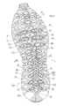
- the outsole 1 in FIG. 2 has a plate-like base 1B and a number of first cleats 1C.
- the plurality of first cleats 1C project from the base 1B toward the lower Z to form the ground contact surface 10, and are arranged in a plurality of rows vertically and horizontally.
- the upper surface 11 of each of the first cleats 1C (most cleats) has a concave surface 1F that is recessed toward the lower side Z.
- the midsole 2 is thicker on the convex surface 2F than the base 2B around the convex portion 2P.
- the lower surface 20 of the generally flat base 2B of the midsole 2 is bonded or welded to the upper surface 11 of the generally flat base 1B of the outsole 1.
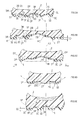
- a line L1 in FIG. 3 and FIGS. 5A to 5E indicates a reference line.
- the plurality of first cleats 1C in FIG. 5B have an outer peripheral surface 1R between the grounding surface 10 and the base 1B.
- the thickness of the outsole 1 on the outer peripheral surface 1R becomes thinner toward the upper side and thicker toward the lower side. Is formed.
- a part of the first cleat 1C for example, the outer peripheral surface 1R of the first cleat 1C in FIG. 5A extends obliquely downward from the base 1B toward the grounding surface 10 and is joined to the peripheral edge of the convex surface 2F. It has an edge 1E, and the thickness Tr of the upper edge 1E is slightly smaller than the thickness Tb of the base 1B.
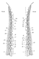
- some of the first cleats 1C are intermittently disposed on the inner edge 1M and the outer edge 1L of the shoe sole, and the side surface of the convex portion 2P is the inner edge 1M. And exposed at the outer edge 1L. 4A and 4B, a halftone dot is attached to the side surface of the midsole 2.
- a part of the first cleat 1C is intermittently arranged on the inner edge 1M of the shoe sole, and the side surface of the convex portion 2P is exposed at the inner edge 1M. Therefore, the interface between the upper surface 11 of the outsole 1 and the lower surface 20 of the midsole 2 is such that a part of the convex surface 2F appears over the length (more than half) of the inner edge 1M, and a wave shape is formed at the inner edge 1M. It appears as a continuous curve.
- the interface between the upper surface 11 of the outsole 1 and the lower surface 20 of the midsole 2 is such that a part of the convex surface 2F appears over the length (more than half) of the outer edge 1L, and a wave shape is formed at the outer edge 1L. It appears as a continuous curve.
- the inner and outer edges 1M and 1L are flexible due to being formed in a wave shape, and as shown by the arrows in FIG. 5D, the inner and outer centers of the midsole 2 are likely to sink downward. right.
- the plurality of first cleats 1C of the side edges 1M and 1L have an outer peripheral surface 1R between the grounding surface 10 and the base 1B, and FIGS. 5B, 5C, and 5E.
- the thickness of the outsole 1 on the outer peripheral surface 1R is formed so as to be thinner toward the upper side and thicker toward the lower side.
- the first through hole H ⁇ b> 1 is formed in a base portion 1 ⁇ / b> B surrounded by three or four of the first cleats 1 ⁇ / b> C of the outsole 1.
- the first cleat 2C of the midsole 2 protrudes downward Z through the first through hole H1.
- the outsole 1 is provided with a second cleat that does not have a normal concave surface 1F, for example, different from the cleat 1C, and three or four or more of the second cleat or the first cleat C1 are provided.
- the first through hole H1 and the first cleat 2C of the midsole 2 may be provided in the base 1B surrounded by the cleats.
- the base 1 ⁇ / b> B of the outsole 1 is formed in a lattice shape in the central region 5 ⁇ / b> A of the rear foot 5 ⁇ / b> R, and several (three) or more through holes H ⁇ b> 2 are formed. ing. These second through holes H2 are provided adjacent to each other in the central region 5A of the rear foot portion 5R of the base 1B of the outsole 1. Each second cleat 20C of the midsole 2 protrudes downward Z through each second through hole H2 for each through hole H2.
- the hard first cleat 1C of the outsole 1 is disposed around the group of the second cleats 20C, that is, the front, rear, inner side M, and outer side.
- the top 2T of the first and second cleats 2C and 20C made of the foam of FIG. 1 and FIG. 5D is the same as that of the first cleat 1C of the outsole 1. It is further away from the road surface than the ground plane 10. Therefore, it will be difficult to ground on a flat road surface, and will be grounded on a hard road surface with many stones.
- the strengthening device 29 may not be provided.
- a groove may be provided around the outsole cleat.
- the midsole and / or the outsole may be formed of a plurality of members. Accordingly, such changes and modifications are to be construed as within the scope of the invention as defined by the claims.
- the present invention can be used for the soles of walk shoes, rain shoes, and everyday shoes in addition to exercise shoes for trail running, mountain climbing, cross country use and the like.
Landscapes
- Chemical & Material Sciences (AREA)
- Engineering & Computer Science (AREA)
- Materials Engineering (AREA)
- Health & Medical Sciences (AREA)
- General Health & Medical Sciences (AREA)
- Physical Education & Sports Medicine (AREA)
- Footwear And Its Accessory, Manufacturing Method And Apparatuses (AREA)
Abstract
Description
つまり、同先行技術のFIG.6の高硬度のベースは下部が薄肉で、かつ、上部が厚肉になっており、そのため、スタッドが無垢である場合の方が柔軟さが増し、グリップ性は高くなるだろう。
上面21および下面20を有し前記アウトソール1の前記上面11に前記下面20が付着され熱可塑性の樹脂成分を有する発泡体を主体とするミッドソール2とを備え、
前記アウトソール1は、
ベース1Bと、
前記ベース1Bから下方Zに向かって突出して前記接地面10を形成し、縦横にそれぞれ複数配置された複数の第1クリート1Cと、
前記各第1クリート1Cの上面11において下方Zに向かって窪んだ凹面1Fとを有し、
前記ミッドソール2の前記下面20は前記ミッドソール2のベース2Bから下方Zに向かって突出する凸部2Pの表面で形成された凸面2Fを有し、
前記凹面1Fと凸面2Fとは互いに接し、かつ付着され、
前記各第1クリート1Cにおける前記接地面10から前記凸面2Fのトップ2Tまでの距離1Dが、前記ベース1Bの厚さよりも大きい。
なお、厚さは、部材の表面に対する法線方向に測定すべきである。
(1)各第1クリート1Cの周囲の各ベース1Bと当該第1クリート1Cとの関係において、前記距離1Dが前記ベース1Bの厚さよりも大きい。
(2)各第1クリート1Cの周囲の各ベース1Bと当該第1クリート1Cとの関係において、前記距離1Dが前記ベース1Bの厚さの平均値よりも大きい。
(3)各第1クリート1Cの周囲の各ベース1Bと当該第1クリート1Cとの関係において、当該クリート1Cの周囲のベース1Bに溝などの窪みが形成されている場合において、前記距離1Dが前記ベース1Bの厚さの最大値よりも大きい。
(4)各第1クリート1Cの周囲の各ベース1Bと当該第1クリート1Cとの関係において、前記距離1Dが前記ベース1Bの厚さの最小値よりも大きい。
(5)隣り合う第1クリート1Cの間の板状ないし平板状のベース1Bと当該複数の第1クリート1Cとの関係において、前記各距離1Dが前記板状のベース1Bの厚さよりも大きい。
(6)隣り合う第1クリート1Cの間の板状ないし平板状のベース1Bと当該複数の第1クリート1Cとの関係において、前記各距離1Dの平均値が前記ベース1Bの厚さの平均値よりも大きい。
(7)隣り合う第1クリート1Cの間の板状ないし平板状のベース1Bと当該複数の第1クリート1Cとの関係において、当該クリート1Cの周囲のベース1Bに溝などの窪みが形成されている場合において前記距離1Dの最小値が前記ベース1Bの厚さの最大値よりも大きい。
(8)隣り合う第1クリート1Cの間に凸部を有するベース1Bと当該第1クリート1Cとの関係において、前記距離1Dの最大値、最小値または平均値のいずれか1以上が前記ベース1Bの厚さの最大値または平均値よりも大きい。
なお、板状ないし平板状とは、ベース1Bが突出したクリートを形成していないことを意味する。また、「接地面10」とはソールを平らな路面に配置して接地する面をいい、したがって、1つのクリートの中央に凹所がある場合、当該凹所は前記接地面10を形成しない。
前記外周面1Rにおけるアウトソール1の肉厚が、上方に向かうに従い薄く、かつ、下方に向かうに従い厚く形成されている。
前記上縁部1Eの肉厚が前記ベース1Bの肉厚よりも小さい。
前記アウトソール1の上面11とミッドソール2の下面20との界面が前記内側縁1M又は外側縁1Lにおいて波形状の曲線となって表れている。
前記アウトソール1の上面11とミッドソール2の下面20との界面が前記内側縁1Mにおいて波形状の曲線となって表れ、
前記第1クリート1Cが前記靴底の外側縁1Lに断続的に複数個配置され、前記凸部2Pの側面が前記外側縁1Lにおいて露出しており、
前記アウトソール1の上面11とミッドソール2の下面20との界面が前記外側縁1Lにおいて波形状の曲線となって表れており、
これらの複数の第1クリート1Cは、前記接地面10と前記ベース1Bとの間に外周面1Rを有し、
前記外周面1Rにおけるアウトソール1の肉厚が、上方に向かうに従い薄く、かつ、下方に向かうに従い厚く形成されている。
本実施例の場合、前記内側縁1M及び外側縁1Lの双方においてクリート1Cが断続的に複数個配置されている。そのため、走行中に内側縁1M及び外側縁1Lが足の長軸に沿った位置よりも上方に変位し、したがって、足の長軸に沿ってミッドソール2の上面21が沈むだろう。その結果、走行の安定性が向上するかもしれない。
前記ミッドソール2は前記第1貫通孔H1を通して下方Zに突出する前記発泡体からなる別の第1クリート2Cを有する。
ここで、ミッドソール2とアウトソール1とは互いに接着ないし溶着されて、互いに一体となっていることで、厚さが増加して曲げに対する剛性、つまり、曲げ剛性EIZが著しく増加する。この曲げ剛性EIZは素材のヤング率に比例する。したがって、ミッドソール2の第1クリート2C、並びに、アウトソール1に形成された第1貫通孔H1は曲げ剛性EIZの低下に寄与し、靴底の屈曲性が向上するだろう。
前記ミッドソール2は前記第2貫通孔H2を通して下方Zに突出する前記発泡体からなる別の第2クリート20Cを複数有する。
特に、複数の第2貫通孔H2およびクリート20Cが後足部5Rの中央領域5Aに設けられており、後足部5Rにグリップ性能を付えつつ、後足部5Rの踵に適度なクッションを与えるだろう。
前記ミッドソール2は前記第1貫通孔H1を通して下方Zに突出する前記発泡体からなる別の第1クリート2Cを複数有し、
前記アウトソール1のベース1Bは後足部5Rの中央領域において複数の第2貫通孔H2を定義し、
前記ミッドソール2は前記各第2貫通孔H2を通して下方Zに突出する前記発泡体からなる別の第2クリート20Cを複数有し、
前記ミッドソール2の第1および第2クリート2C,20Cの数の合計が6~40個に設定されている。
また、6~40個のミッドソール2の第1および第2クリート2C,20Cは靴底の新たなデザインを提供するだろう。
かかるデザイン性やトレールランニングにおける滑り防止の観点からミッドソール2の第1および第2クリート2C,20Cの数は8~35個が好ましく、10~30個程度が最も好ましいだろう。
一般に、ミッドソール2はアウトソール1に比べ柔軟であり、硬度がアウトソール1よりも遙に小さい。しかし、両者の硬度の測定方法は互いに異なり、そのため、両者の硬度の関係に代えてヤング率の概念を用いた。
本実施例は例えばトレールランニング用の靴の靴底である。
図2に示すように、靴底はゴム製の1枚のアウトソール1と樹脂製の1枚のミッドソール2とを備える。なお、靴底の上には足の甲を包むアッパー(図示せず)が設けられる。
なお、図1~図3においてはミッドソール2の第1および第2クリート2C,20Cには、網点が付されている。
なお、図3および、図5A-図5EのラインL1は基準線を示す。
なお、後足部5Rの中央領域5Aとは、後足部5Rの前後端および内外側縁1M,1Lを除く後足部5Rの領域を意味する。
たとえば、強化装置29は設けられなくてもよい。また、アウトソールのクリートの周りに溝を設けてもよい。また、ミッドソール及び/又はアウトソールはそれぞれ複数枚の部材で形成されていてもよい。
したがって、そのような変更および修正は、請求の範囲から定まる本発明の範囲のものと解釈される。
2:ミッドソール 2B:ベース 2C:第1クリート 20C:第2クリート 2F:凸面 2P:凸部 2T:トップ 20:下面 21:上面 29:強化装置
5R:後足部 5A:中央領域
H1:第1貫通孔 H2:第2貫通孔
L:外側 L1:基準ライン M:内側
Z:下方
Claims (12)
- 靴底であって、
接地面10と上面11とを有するゴム製のアウトソール1と、
上面21および下面20を有し前記アウトソール1の前記上面11に前記下面20が付着され熱可塑性の樹脂成分を有する発泡体を主体とするミッドソール2とを備え、
前記アウトソール1は、
ベース1Bと、
前記ベース1Bから下方Zに向かって突出して前記接地面10を形成し、縦横にそれぞれ複数配置された複数の第1クリート1Cと、
前記各第1クリート1Cの上面11において下方Zに向かって窪んだ凹面1Fとを有し、
前記ミッドソール2の前記下面20は前記ミッドソール2のベース2Bから下方Zに向かって突出する凸部2Pの表面で形成された凸面2Fを有し、
前記凹面1Fと凸面2Fとは互いに接し、かつ付着され、
前記各第1クリート1Cにおける前記接地面10から前記凸面2Fのトップ2Tまでの距離1Dが、前記ベース1Bの厚さよりも大きい。 - 請求項1の靴底において、
前記ミッドソール2は前記凸面2Fにおいて、前記凸部2Pの周囲の前記ベース2Bよりも厚い。 - 請求項1もしくは2の靴底において、
前記複数の第1クリート1Cは、前記接地面10と前記ベース1Bとの間に外周面1Rを有し、
前記外周面1Rにおけるアウトソール1の肉厚が、上方に向かうに従い薄く、かつ、下方に向かうに従い厚く形成されている。 - 請求項1,2もしくは3の靴底において、
前記第1クリート1Cは前記ベース1Bから前記接地面10に向かって斜めに延び、かつ、前記凸面2Fの周縁に接合された上縁部1Eを有し、
前記上縁部1Eの肉厚が前記ベース1Bの肉厚よりも小さい。 - 請求項1~4のいずれか1項の靴底において、
前記第1クリート1Cが前記靴底の内側縁1M及び/又は外側縁1Lに配置され、前記凸部2Pの側面が前記内側縁1M及び/又は外側縁1Lにおいて露出している。 - 請求項1~4のいずれか1項の靴底において、
前記第1クリート1Cが前記靴底の内側縁1M又は外側縁1Lに断続的に複数個配置され、前記凸部2Pの側面が前記内側縁1M又は外側縁1Lにおいて露出しており、
前記アウトソール1の上面11とミッドソール2の下面20との界面が前記内側縁1M又は外側縁1Lにおいて波形状の曲線となって表れている。 - 請求項1~4のいずれか1項の靴底において、
前記第1クリート1Cが前記靴底の内側縁1Mに断続的に複数個配置され、前記凸部2Pの側面が前記内側縁1Mにおいて露出しており、
前記アウトソール1の上面11とミッドソール2の下面20との界面が前記内側縁1Mにおいて波形状の曲線となって表れ、
前記第1クリート1Cが前記靴底の外側縁1Lに断続的に複数個配置され、前記凸部2Pの側面が前記外側縁1Lにおいて露出しており、
前記アウトソール1の上面11とミッドソール2の下面20との界面が前記外側縁1Lにおいて波形状の曲線となって表れており、
これらの複数の第1クリート1Cは、前記接地面10と前記ベース1Bとの間に外周面1Rを有し、
前記外周面1Rにおけるアウトソール1の肉厚が、上方に向かうに従い薄く、かつ、下方に向かうに従い厚く形成されている。 - 請求項1~7のいずれか1項の靴底において、
前記アウトソール1は3個以上の前記第1クリート1C又は前記第1クリート1Cとは別の複数の第2クリートを有し、これらの第1及び/又は第2クリートのうち3個以上の前記クリートに囲まれた部位において第1貫通孔H1を定義し、
前記ミッドソール2は前記第1貫通孔H1を通して下方Zに突出する前記発泡体からなる別の第1クリート2Cを有する。 - 請求項1~8のいずれか1項の靴底において、
前記アウトソール1のベース1Bは後足部5Rの中央領域5Aにおいて複数の貫通孔H2を定義し、
前記ミッドソール2は前記第2貫通孔H2を通して下方Zに突出する前記発泡体からなる別の第2クリート20Cを複数有する。 - 請求項1~7のいずれか1項の靴底において、
前記アウトソール1は3個以上の前記第1クリート1C又は前記第1クリート1Cとは別の複数の第2クリートを有し、これらの第1及び/又は第2クリートのうち3個以上の前記クリートに囲まれた部位において第1貫通孔H1を定義し、
前記ミッドソール2は前記第1貫通孔H1を通して下方Zに突出する前記発泡体からなる別の第1クリート2Cを複数有し、
前記アウトソール1のベース1Bは後足部5Rの中央領域5Aにおいて複数の第2貫通孔H2を定義し、
前記ミッドソール2は前記各第2貫通孔H2を通して下方Zに突出する前記発泡体からなる別の第2クリート20Cを複数有し、
前記ミッドソール2の第1および第2クリート2C,20Cの数の合計が6~40個に設定されている。 - 請求項8もしくは9の靴底において、
靴底が無負荷の状態において、
前記発泡体からなる第1及び第2クリート2C,20Cのトップ2Tは前記アウトソール1の第1及び第2クリート1C,10Cの接地面10よりも路面から離間している。 - 請求項1~11のいずれか1項の靴底において、
前記アウトソール1のヤング率は前記ミッドソール2のヤング率よりも大きい。
Priority Applications (4)
| Application Number | Priority Date | Filing Date | Title |
|---|---|---|---|
| JP2015541383A JP6055554B2 (ja) | 2013-10-10 | 2013-10-10 | 靴底 |
| US15/027,679 US9867427B2 (en) | 2013-10-10 | 2013-10-10 | Shoe sole |
| EP13895346.8A EP3056104B1 (en) | 2013-10-10 | 2013-10-10 | Shoe sole |
| PCT/JP2013/077631 WO2015052814A1 (ja) | 2013-10-10 | 2013-10-10 | 靴底 |
Applications Claiming Priority (1)
| Application Number | Priority Date | Filing Date | Title |
|---|---|---|---|
| PCT/JP2013/077631 WO2015052814A1 (ja) | 2013-10-10 | 2013-10-10 | 靴底 |
Publications (1)
| Publication Number | Publication Date |
|---|---|
| WO2015052814A1 true WO2015052814A1 (ja) | 2015-04-16 |
Family
ID=52812661
Family Applications (1)
| Application Number | Title | Priority Date | Filing Date |
|---|---|---|---|
| PCT/JP2013/077631 Ceased WO2015052814A1 (ja) | 2013-10-10 | 2013-10-10 | 靴底 |
Country Status (4)
| Country | Link |
|---|---|
| US (1) | US9867427B2 (ja) |
| EP (1) | EP3056104B1 (ja) |
| JP (1) | JP6055554B2 (ja) |
| WO (1) | WO2015052814A1 (ja) |
Cited By (1)
| Publication number | Priority date | Publication date | Assignee | Title |
|---|---|---|---|---|
| JPWO2019073609A1 (ja) * | 2017-10-13 | 2020-07-16 | 株式会社アシックス | 靴底及びシューズ |
Families Citing this family (70)
| Publication number | Priority date | Publication date | Assignee | Title |
|---|---|---|---|---|
| AU2013388295B2 (en) | 2013-05-01 | 2018-07-05 | Asics Corporation | Member for shoe sole |
| EP3056103B1 (en) * | 2013-10-10 | 2019-12-25 | ASICS Corporation | Shoe sole |
| USD744212S1 (en) * | 2013-12-13 | 2015-12-01 | Reebok International Limited | Shoe |
| USD749310S1 (en) | 2013-12-13 | 2016-02-16 | Reebok International Limited | Shoe |
| US9687044B2 (en) * | 2014-07-24 | 2017-06-27 | Nike, Inc. | Footwear with sole structure incorporating lobed fluid-filled chamber with protruding end wall portions |
| DE102015208763A1 (de) * | 2015-05-12 | 2016-11-17 | Adidas Ag | Anpassbares Schuhoberteil und anpassbare Sohle |
| US11206890B2 (en) * | 2015-11-20 | 2021-12-28 | Nike, Inc. | Ground-engaging structures for articles of footwear |
| USD779174S1 (en) * | 2015-12-22 | 2017-02-21 | Nike, Inc. | Shoe midsole |
| US20170224053A1 (en) * | 2016-02-05 | 2017-08-10 | Ecco Sko A/S | Outer sole for spikeless footwear |
| USD814156S1 (en) | 2016-03-09 | 2018-04-03 | Under Armour, Inc. | Shoe sole |
| USD804157S1 (en) * | 2016-05-15 | 2017-12-05 | Nike, Inc. | Shoe midsole |
| USD824147S1 (en) * | 2016-05-16 | 2018-07-31 | Nike, Inc. | Shoe |
| USD794299S1 (en) * | 2016-06-30 | 2017-08-15 | Nike, Inc. | Shoe outsole |
| USD862051S1 (en) * | 2016-07-18 | 2019-10-08 | Adidas Ag | Sole |
| USD814758S1 (en) * | 2016-08-15 | 2018-04-10 | Ecco Sko A/S | Sole |
| USD808625S1 (en) * | 2016-08-15 | 2018-01-30 | Nike, Inc. | Shoe outsole |
| USD862052S1 (en) * | 2016-09-08 | 2019-10-08 | Decathlon | Footwear with surface pattern |
| USD821717S1 (en) * | 2016-09-12 | 2018-07-03 | Under Armour, Inc. | Sole structure |
| USD811063S1 (en) * | 2016-11-12 | 2018-02-27 | Nike, Inc. | Shoe outsole |
| USD808140S1 (en) * | 2016-11-14 | 2018-01-23 | Nike, Inc. | Shoe outsole |
| US11019884B2 (en) * | 2016-11-23 | 2021-06-01 | Nike, Inc. | Sole structure having a midsole component with movable traction members |
| USD801014S1 (en) * | 2016-12-05 | 2017-10-31 | Converse Inc. | Shoe midsole |
| IT201600130908A1 (it) * | 2016-12-23 | 2018-06-23 | Alberto Del Biondi S P A | Calzatura con intersuola |
| US11752413B2 (en) * | 2016-12-31 | 2023-09-12 | Under Armour, Inc. | Article of footwear with multiple durometer outsole and directional cleat pattern |
| USD848131S1 (en) | 2017-02-01 | 2019-05-14 | Fuerst Group, Inc. | Outsole for a footwear article |
| USD821719S1 (en) * | 2017-02-13 | 2018-07-03 | Nike, Inc. | Shoe outsole |
| USD829424S1 (en) * | 2017-03-06 | 2018-10-02 | Nike, Inc. | Shoe outsole |
| USD831318S1 (en) * | 2017-03-31 | 2018-10-23 | Christian Louboutin | Shoe sole |
| USD826527S1 (en) * | 2017-04-05 | 2018-08-28 | Nike, Inc. | Shoe outsole |
| USD824152S1 (en) * | 2017-04-14 | 2018-07-31 | Nike, Inc. | Shoe outsole |
| USD823584S1 (en) * | 2017-04-14 | 2018-07-24 | Nike, Inc. | Shoe outsole |
| USD832563S1 (en) * | 2017-04-14 | 2018-11-06 | Nike, Inc. | Shoe outsole |
| USD852483S1 (en) * | 2017-04-28 | 2019-07-02 | Vans, Inc. | Shoe outsole |
| US10952496B2 (en) | 2017-05-09 | 2021-03-23 | Under Armour, Inc. | Article of footwear with interlocking midsole member |
| USD826528S1 (en) * | 2017-05-15 | 2018-08-28 | Nike, Inc. | Shoe outsole |
| USD836312S1 (en) * | 2017-05-15 | 2018-12-25 | Under Armour, Inc. | Article of footwear |
| USD816965S1 (en) * | 2017-10-11 | 2018-05-08 | Skechers U.S.A., Inc. Ii | Shoe outsole bottom |
| USD818254S1 (en) * | 2017-10-12 | 2018-05-22 | Skechers U.S.A., Inc. Ii | Shoe outsole bottom |
| USD841964S1 (en) * | 2017-11-10 | 2019-03-05 | Reebok International Limited | Sole |
| USD822351S1 (en) * | 2017-12-19 | 2018-07-10 | Nike, Inc. | Shoe |
| USD863743S1 (en) | 2018-01-09 | 2019-10-22 | Adidas Ag | Shoe |
| USD889788S1 (en) * | 2018-02-23 | 2020-07-14 | Sumitomo Rubber Industries, Ltd. | Shoe midsole |
| USD901154S1 (en) * | 2018-05-04 | 2020-11-10 | J & B Yang Corporation | Slip resistant outsole |
| USD872983S1 (en) | 2018-06-20 | 2020-01-21 | Christian Louboutin | Sole for footwear |
| USD879438S1 (en) | 2018-08-09 | 2020-03-31 | Reebok International Limited | Shoe |
| USD879437S1 (en) | 2018-08-09 | 2020-03-31 | Reebok International Limited | Shoe |
| USD889099S1 (en) * | 2018-11-09 | 2020-07-07 | J. Choo Limited | Sole for footwear |
| USD879427S1 (en) * | 2018-11-09 | 2020-03-31 | J. Choo Limited | Sole for footwear |
| US12171300B2 (en) * | 2019-03-28 | 2024-12-24 | Nike, Inc. | Sole structure of an article of footwear |
| CN210611192U (zh) * | 2019-04-03 | 2020-05-26 | 霍尼韦尔国际公司 | 具有阻力元件的鞋类外底 |
| USD929722S1 (en) * | 2019-05-15 | 2021-09-07 | Fly Kytin Corp. | Sole for footwear |
| USD900443S1 (en) * | 2019-05-17 | 2020-11-03 | Nike, Inc. | Shoe |
| USD912376S1 (en) * | 2019-07-18 | 2021-03-09 | You Rao | Footwear sole |
| USD917138S1 (en) * | 2019-08-27 | 2021-04-27 | Deckers Outdoor Corporation | Footwear midsole |
| USD934539S1 (en) * | 2020-03-10 | 2021-11-02 | Paloïse Sas | Sole for footwear |
| CN121621634A (zh) * | 2020-07-13 | 2026-03-10 | 耐克创新有限合伙公司 | 具有用于向前动量的鞋底夹层突起和弧形轮廓的鞋底结构 |
| USD968766S1 (en) * | 2020-12-08 | 2022-11-08 | J. Choo Limited | Footwear |
| USD977797S1 (en) * | 2020-12-09 | 2023-02-14 | Converse Inc. | Shoe |
| USD978509S1 (en) * | 2020-12-09 | 2023-02-21 | Converse Inc. | Shoe |
| USD950912S1 (en) * | 2020-12-29 | 2022-05-10 | J. Choo Limited | Sole for footwear |
| JP7699652B2 (ja) * | 2021-04-20 | 2025-06-27 | 株式会社アシックス | 靴底および靴 |
| USD1103598S1 (en) * | 2021-05-25 | 2025-12-02 | Jiawei Lin | Running shoe |
| USD996002S1 (en) * | 2021-07-22 | 2023-08-22 | Valentino S.P.A. | Shoe |
| JP1745872S (ja) | 2021-08-05 | 2023-06-08 | 靴底 | |
| USD1010996S1 (en) * | 2021-08-19 | 2024-01-16 | Converse Inc. | Shoe |
| USD980601S1 (en) * | 2021-11-05 | 2023-03-14 | Chenliang Zhong | Shoe sole |
| USD981096S1 (en) * | 2021-11-22 | 2023-03-21 | Guohai Wang | Sole |
| USD1116391S1 (en) * | 2022-01-20 | 2026-03-10 | Zackary Zenon Contreras | Snakeskin patterned sole for sandals and other shoes |
| USD994290S1 (en) * | 2022-08-03 | 2023-08-08 | Hui Jiang | Outsole |
| USD1111374S1 (en) * | 2023-05-23 | 2026-02-10 | Louis Vuitton Malletier | Sole for footwear |
Citations (9)
| Publication number | Priority date | Publication date | Assignee | Title |
|---|---|---|---|---|
| JPS5690105U (ja) * | 1980-11-27 | 1981-07-18 | ||
| JPH0438701U (ja) | 1990-07-30 | 1992-04-02 | ||
| JPH0565201U (ja) | 1992-02-17 | 1993-08-31 | 月星化成株式会社 | 射出成形長靴 |
| JPH07265103A (ja) | 1993-12-28 | 1995-10-17 | Midori Anzen Co Ltd | 靴底及びその製造方法 |
| JPH11137305A (ja) * | 1997-11-11 | 1999-05-25 | Bridgestone Sports Co Ltd | スポーツシューズ |
| JP2005185303A (ja) | 2003-12-24 | 2005-07-14 | Asics Corp | スパイクシューズのソールおよびその製造方法 |
| JP3120866U (ja) * | 2006-02-06 | 2006-04-20 | 株式会社シモン | 耐滑性および耐経時変化性に優れた靴表底構造 |
| JP2007312856A (ja) * | 2006-05-23 | 2007-12-06 | Asics Corp | スタッド、及びスパイクシューズ |
| WO2010038266A1 (ja) | 2008-09-30 | 2010-04-08 | 株式会社アシックス | 走行効率の良い運動靴の靴底 |
Family Cites Families (69)
| Publication number | Priority date | Publication date | Assignee | Title |
|---|---|---|---|---|
| FR2374863A1 (fr) * | 1976-07-29 | 1978-07-21 | Adidas Chaussures | Semelle pour chaussures de sport et de loisir |
| JPS5690105A (en) | 1979-12-24 | 1981-07-22 | Kayaba Ind Co Ltd | Controlling valve for farm working machinery of agricultural tractor |
| US4481727A (en) * | 1980-05-06 | 1984-11-13 | Pensa, Inc. | Shoe sole construction |
| FR2632497A1 (fr) * | 1988-03-22 | 1989-12-15 | Beneteau Charles Marie | Semelle de chaussures pour la pratique des sports et activites analogues |
| JPH0438701A (ja) | 1990-06-01 | 1992-02-07 | Toshiba Corp | 磁気記録再生装置 |
| US5155927A (en) | 1991-02-20 | 1992-10-20 | Asics Corporation | Shoe comprising liquid cushioning element |
| JP3350863B2 (ja) | 1991-04-26 | 2002-11-25 | ダウ・ケミカル日本株式会社 | 水田除草用粒剤組成物 |
| US5367791A (en) * | 1993-02-04 | 1994-11-29 | Asahi, Inc. | Shoe sole |
| US5718063A (en) | 1995-07-17 | 1998-02-17 | Asics Corporation | Midsole cushioning system |
| JP3258628B2 (ja) | 1998-09-08 | 2002-02-18 | 株式会社アシックス | 運動靴 |
| JP3238132B2 (ja) | 1998-10-02 | 2001-12-10 | 美津濃株式会社 | スポーツ用シューズのミッドソール構造 |
| US6438870B2 (en) | 1998-11-05 | 2002-08-27 | Asics Corporation | Shoe sole with shock absorber structure |
| JP3396637B2 (ja) | 1998-11-05 | 2003-04-14 | 株式会社アシックス | 靴底におけるシャンクの支持構造 |
| US6467197B1 (en) | 1999-05-31 | 2002-10-22 | Asics Corp. | Shoe with arch reinforcement |
| JP2001046113A (ja) * | 1999-08-11 | 2001-02-20 | Descente Ltd | スパイクシューズのソール |
| JP4076704B2 (ja) * | 2000-05-09 | 2008-04-16 | 美津濃株式会社 | スポーツ用シューズのソール構造 |
| JP3979765B2 (ja) | 2000-05-15 | 2007-09-19 | 株式会社アシックス | 靴底の緩衝装置 |
| JP3921453B2 (ja) | 2003-04-04 | 2007-05-30 | 株式会社アシックス | 足の傾角測定方法、靴または靴用中敷選択方法、靴または靴用中敷製造方法、および、足の傾角測定装置 |
| USD495860S1 (en) | 2003-07-18 | 2004-09-14 | Asics Corp | Shoe outsole |
| USD496148S1 (en) | 2003-07-18 | 2004-09-21 | Asics Corporation | Pair of shoe outsoles |
| USD522229S1 (en) | 2003-07-18 | 2006-06-06 | Asics Corp. | Pair of shoe midsoles |
| USD501713S1 (en) | 2003-07-18 | 2005-02-15 | As/Cs Corporation | Shoe midsole |
| USD501987S1 (en) | 2003-08-20 | 2005-02-22 | Asics Corporation | Shoe midsole |
| USD495859S1 (en) | 2003-08-20 | 2004-09-14 | Asics Corporation | Pair of shoe outsoles |
| JP3822631B2 (ja) | 2003-10-17 | 2006-09-20 | 株式会社アシックス | 強化構造を備えた靴底 |
| US7322131B2 (en) | 2003-11-27 | 2008-01-29 | Asics Corp. | Shoe with slip preventive member |
| USD512819S1 (en) | 2004-05-27 | 2005-12-20 | Asics Corporation | Pair of shoe outsoles |
| USD512828S1 (en) | 2004-05-27 | 2005-12-20 | Asics Corporation | Pair of shoe midsoles |
| USD512827S1 (en) | 2004-05-27 | 2005-12-20 | Asics Corporation | Pair of shoe midsoles |
| USD512208S1 (en) | 2004-05-27 | 2005-12-06 | Asics Corporation | Pair of shoe outsoles |
| USD520732S1 (en) | 2004-05-27 | 2006-05-16 | Asics Corporation | Pair of shoe midsoles |
| USD512818S1 (en) | 2004-05-27 | 2005-12-20 | Asics Corp. | Pair of shoe outsoles |
| WO2006038357A1 (ja) | 2004-09-30 | 2006-04-13 | Asics Corporation | 靴底の緩衝装置 |
| CN100425175C (zh) | 2004-09-30 | 2008-10-15 | 株式会社爱世克私 | 鞋底的后足部的缓冲装置 |
| USD513115S1 (en) | 2004-11-15 | 2005-12-27 | Asics Corporation | Pair of shoe midsoles |
| USD509351S1 (en) | 2004-11-15 | 2005-09-13 | Asics Corporation | Shoe midsole |
| USD514286S1 (en) | 2004-11-15 | 2006-02-07 | Asics Corporation | Pair of shoe outsoles |
| USD575946S1 (en) | 2005-03-29 | 2008-09-02 | Asics Corporation | Pair of heels for shoe outsoles |
| USD553846S1 (en) | 2005-04-26 | 2007-10-30 | Asics Corporation | Shoe outsole and midsole |
| KR101229688B1 (ko) | 2005-05-10 | 2013-02-05 | 갸부시끼가이샤아식스 | 구두창용 부재 |
| DE112005003570B4 (de) | 2005-05-13 | 2017-11-09 | Asics Corp. | Stoßabsorptionsvorrichtung für Schuhsohle |
| KR100683242B1 (ko) * | 2005-06-03 | 2007-02-15 | 주식회사 트렉스타 | 신발 밑창 |
| USD542522S1 (en) | 2005-10-11 | 2007-05-15 | Asics Corporation | Shoe midsole |
| WO2007046277A1 (ja) | 2005-10-20 | 2007-04-26 | Asics Corporation | 強化構造を備えた靴底 |
| JP4886774B2 (ja) | 2006-04-21 | 2012-02-29 | 株式会社アシックス | 強化構造を備えた靴底および緩衝構造を備えた靴底 |
| USD552833S1 (en) | 2006-05-05 | 2007-10-16 | Asics Corp. | Shoe |
| USD561434S1 (en) | 2006-08-01 | 2008-02-12 | Asics Corp. | Pair of shoe outsoles |
| USD561442S1 (en) | 2006-08-01 | 2008-02-12 | Asics Corp. | Pair of shoe outsoles |
| US9089185B2 (en) | 2006-10-20 | 2015-07-28 | Asics Corporation | Structure of front foot portion of shoe sole |
| USD582658S1 (en) | 2007-04-06 | 2008-12-16 | Asics Corporation | Shoe |
| USD575486S1 (en) | 2007-05-11 | 2008-08-26 | Asics Corporation | Pair of shoe outsoles |
| US7941941B2 (en) * | 2007-07-13 | 2011-05-17 | Nike, Inc. | Article of footwear incorporating foam-filled elements and methods for manufacturing the foam-filled elements |
| USD571090S1 (en) | 2007-07-17 | 2008-06-17 | Asics Corporation | Pair of shoe outsoles |
| US8220185B2 (en) * | 2009-01-29 | 2012-07-17 | Nike, Inc. | Article of footwear with suspended stud assembly |
| US8171655B2 (en) * | 2009-03-18 | 2012-05-08 | Wolverine World Wide, Inc. | Sole construction and related method of manufacture |
| USD650566S1 (en) | 2010-05-07 | 2011-12-20 | Asics Corporation | Shoe |
| US9210967B2 (en) * | 2010-08-13 | 2015-12-15 | Nike, Inc. | Sole structure with traction elements |
| EP2687116A4 (en) | 2011-03-18 | 2015-05-06 | Asics Corp | REINFORCEMENT OF A FIBER-REINFORCED SPIKESOLE |
| US8931187B2 (en) | 2011-08-25 | 2015-01-13 | Tbl Licensing Llc | Wave technology |
| EP2805637B1 (en) | 2012-01-18 | 2019-09-18 | ASICS Corporation | Foam sole, and shoes |
| EP2815668B1 (en) | 2012-02-17 | 2019-02-06 | ASICS Corporation | Shoe and manufacturing method therefor |
| US20150135558A1 (en) | 2012-05-10 | 2015-05-21 | Asics Corporation | Shoe Sole Having Diagonal Groove |
| JP5465814B1 (ja) | 2012-05-10 | 2014-04-09 | 株式会社アシックス | アウトソールおよびミッドソールを備えた靴底 |
| AU2012381265B2 (en) | 2012-05-31 | 2015-02-12 | Asics Corporation | Molded foam article, foamed sole, and shoe |
| JP5350566B1 (ja) | 2012-10-29 | 2013-11-27 | 株式会社アシックス | ウィンドラスメカニズムに着目した靴底 |
| EP2949457A4 (en) | 2013-01-24 | 2016-11-16 | Asics Corp | SHOES AND METHOD FOR THE MANUFACTURE THEREOF |
| WO2014141467A1 (ja) | 2013-03-15 | 2014-09-18 | 株式会社アシックス | 積層構造を持つミッドソール |
| USD734928S1 (en) | 2013-03-28 | 2015-07-28 | Asics Corporation | Footwear sole |
| USD734927S1 (en) | 2013-03-28 | 2015-07-28 | Asics Corporation | Footwear sole |
-
2013
- 2013-10-10 WO PCT/JP2013/077631 patent/WO2015052814A1/ja not_active Ceased
- 2013-10-10 EP EP13895346.8A patent/EP3056104B1/en active Active
- 2013-10-10 US US15/027,679 patent/US9867427B2/en active Active
- 2013-10-10 JP JP2015541383A patent/JP6055554B2/ja not_active Expired - Fee Related
Patent Citations (10)
| Publication number | Priority date | Publication date | Assignee | Title |
|---|---|---|---|---|
| JPS5690105U (ja) * | 1980-11-27 | 1981-07-18 | ||
| JPH0438701U (ja) | 1990-07-30 | 1992-04-02 | ||
| JPH0565201U (ja) | 1992-02-17 | 1993-08-31 | 月星化成株式会社 | 射出成形長靴 |
| JPH07265103A (ja) | 1993-12-28 | 1995-10-17 | Midori Anzen Co Ltd | 靴底及びその製造方法 |
| JPH11137305A (ja) * | 1997-11-11 | 1999-05-25 | Bridgestone Sports Co Ltd | スポーツシューズ |
| JP2005185303A (ja) | 2003-12-24 | 2005-07-14 | Asics Corp | スパイクシューズのソールおよびその製造方法 |
| JP3120866U (ja) * | 2006-02-06 | 2006-04-20 | 株式会社シモン | 耐滑性および耐経時変化性に優れた靴表底構造 |
| JP2007312856A (ja) * | 2006-05-23 | 2007-12-06 | Asics Corp | スタッド、及びスパイクシューズ |
| WO2010038266A1 (ja) | 2008-09-30 | 2010-04-08 | 株式会社アシックス | 走行効率の良い運動靴の靴底 |
| US20110185590A1 (en) | 2008-09-30 | 2011-08-04 | Asics Corporation | Shoe sole of athletic shoe with high running efficiency |
Cited By (1)
| Publication number | Priority date | Publication date | Assignee | Title |
|---|---|---|---|---|
| JPWO2019073609A1 (ja) * | 2017-10-13 | 2020-07-16 | 株式会社アシックス | 靴底及びシューズ |
Also Published As
| Publication number | Publication date |
|---|---|
| US9867427B2 (en) | 2018-01-16 |
| JP6055554B2 (ja) | 2016-12-27 |
| US20160255911A1 (en) | 2016-09-08 |
| EP3056104B1 (en) | 2020-04-15 |
| EP3056104A1 (en) | 2016-08-17 |
| EP3056104A4 (en) | 2017-06-28 |
| JPWO2015052814A1 (ja) | 2017-03-09 |
Similar Documents
| Publication | Publication Date | Title |
|---|---|---|
| JP6055554B2 (ja) | 靴底 | |
| JP5972476B2 (ja) | 靴底 | |
| CN103313622B (zh) | 具有细长振动吸收后跟系统的鞋类物件 | |
| JP5844952B1 (ja) | グリップ性能を改良した靴底 | |
| JP6310427B2 (ja) | シューズのソール構造 | |
| US7997013B2 (en) | Footwear with a shank system | |
| US6647646B2 (en) | Shoe with arch reinforcement | |
| US20130019505A1 (en) | Footwear with improved sole assembly | |
| JP6722709B2 (ja) | ソール構造およびシューズ | |
| JPWO2018155103A1 (ja) | ソール構造およびそれを用いたシューズ | |
| JP2017023229A (ja) | 野球用スパイクシューズのソール構造 | |
| JP2000083705A (ja) | 靴底構造 | |
| JP2004242692A (ja) | スポーツシューズのソール組立体 | |
| JP2017006293A (ja) | フットウエア用ソール構造体 | |
| JP3114395U (ja) | 耐滑性を有する靴表底構造 | |
| KR100927194B1 (ko) | 신발 | |
| JP5687451B2 (ja) | シューズ | |
| JP4374235B2 (ja) | シューズのソール構造 | |
| JP2002000305A (ja) | 釣靴用の靴底 | |
| JP2000333707A (ja) | 靴底構造 | |
| CN215124868U (zh) | 减震助力支撑鞋底及运动鞋 | |
| JP2013135702A (ja) | 靴底構造 | |
| JP3102375U (ja) | 靴底構造 | |
| JP2004181029A (ja) | シューズのアウトソール構造 | |
| JP2018121836A (ja) | 靴底構造 |
Legal Events
| Date | Code | Title | Description |
|---|---|---|---|
| 121 | Ep: the epo has been informed by wipo that ep was designated in this application |
Ref document number: 13895346 Country of ref document: EP Kind code of ref document: A1 |
|
| ENP | Entry into the national phase |
Ref document number: 2015541383 Country of ref document: JP Kind code of ref document: A |
|
| REEP | Request for entry into the european phase |
Ref document number: 2013895346 Country of ref document: EP |
|
| WWE | Wipo information: entry into national phase |
Ref document number: 2013895346 Country of ref document: EP |
|
| WWE | Wipo information: entry into national phase |
Ref document number: 15027679 Country of ref document: US |
|
| NENP | Non-entry into the national phase |
Ref country code: DE |