WO2015097992A1 - 冷却システムおよび電子機器 - Google Patents
冷却システムおよび電子機器 Download PDFInfo
- Publication number
- WO2015097992A1 WO2015097992A1 PCT/JP2014/006021 JP2014006021W WO2015097992A1 WO 2015097992 A1 WO2015097992 A1 WO 2015097992A1 JP 2014006021 W JP2014006021 W JP 2014006021W WO 2015097992 A1 WO2015097992 A1 WO 2015097992A1
- Authority
- WO
- WIPO (PCT)
- Prior art keywords
- refrigerant
- cooling system
- pipe
- flexible
- port
- Prior art date
- Legal status (The legal status is an assumption and is not a legal conclusion. Google has not performed a legal analysis and makes no representation as to the accuracy of the status listed.)
- Ceased
Links
Images


Classifications
-
- F—MECHANICAL ENGINEERING; LIGHTING; HEATING; WEAPONS; BLASTING
- F28—HEAT EXCHANGE IN GENERAL
- F28D—HEAT-EXCHANGE APPARATUS, NOT PROVIDED FOR IN ANOTHER SUBCLASS, IN WHICH THE HEAT-EXCHANGE MEDIA DO NOT COME INTO DIRECT CONTACT
- F28D15/00—Heat-exchange apparatus with the intermediate heat-transfer medium in closed tubes passing into or through the conduit walls ; Heat-exchange apparatus employing intermediate heat-transfer medium or bodies
- F28D15/02—Heat-exchange apparatus with the intermediate heat-transfer medium in closed tubes passing into or through the conduit walls ; Heat-exchange apparatus employing intermediate heat-transfer medium or bodies in which the medium condenses and evaporates, e.g. heat pipes
- F28D15/0266—Heat-exchange apparatus with the intermediate heat-transfer medium in closed tubes passing into or through the conduit walls ; Heat-exchange apparatus employing intermediate heat-transfer medium or bodies in which the medium condenses and evaporates, e.g. heat pipes with separate evaporating and condensing chambers connected by at least one conduit; Loop-type heat pipes; with multiple or common evaporating or condensing chambers
-
- F—MECHANICAL ENGINEERING; LIGHTING; HEATING; WEAPONS; BLASTING
- F28—HEAT EXCHANGE IN GENERAL
- F28D—HEAT-EXCHANGE APPARATUS, NOT PROVIDED FOR IN ANOTHER SUBCLASS, IN WHICH THE HEAT-EXCHANGE MEDIA DO NOT COME INTO DIRECT CONTACT
- F28D15/00—Heat-exchange apparatus with the intermediate heat-transfer medium in closed tubes passing into or through the conduit walls ; Heat-exchange apparatus employing intermediate heat-transfer medium or bodies
- F28D15/02—Heat-exchange apparatus with the intermediate heat-transfer medium in closed tubes passing into or through the conduit walls ; Heat-exchange apparatus employing intermediate heat-transfer medium or bodies in which the medium condenses and evaporates, e.g. heat pipes
- F28D15/0208—Heat-exchange apparatus with the intermediate heat-transfer medium in closed tubes passing into or through the conduit walls ; Heat-exchange apparatus employing intermediate heat-transfer medium or bodies in which the medium condenses and evaporates, e.g. heat pipes using moving tubes
-
- F—MECHANICAL ENGINEERING; LIGHTING; HEATING; WEAPONS; BLASTING
- F28—HEAT EXCHANGE IN GENERAL
- F28D—HEAT-EXCHANGE APPARATUS, NOT PROVIDED FOR IN ANOTHER SUBCLASS, IN WHICH THE HEAT-EXCHANGE MEDIA DO NOT COME INTO DIRECT CONTACT
- F28D15/00—Heat-exchange apparatus with the intermediate heat-transfer medium in closed tubes passing into or through the conduit walls ; Heat-exchange apparatus employing intermediate heat-transfer medium or bodies
- F28D15/02—Heat-exchange apparatus with the intermediate heat-transfer medium in closed tubes passing into or through the conduit walls ; Heat-exchange apparatus employing intermediate heat-transfer medium or bodies in which the medium condenses and evaporates, e.g. heat pipes
- F28D15/0241—Heat-exchange apparatus with the intermediate heat-transfer medium in closed tubes passing into or through the conduit walls ; Heat-exchange apparatus employing intermediate heat-transfer medium or bodies in which the medium condenses and evaporates, e.g. heat pipes the tubes being flexible
-
- F—MECHANICAL ENGINEERING; LIGHTING; HEATING; WEAPONS; BLASTING
- F28—HEAT EXCHANGE IN GENERAL
- F28D—HEAT-EXCHANGE APPARATUS, NOT PROVIDED FOR IN ANOTHER SUBCLASS, IN WHICH THE HEAT-EXCHANGE MEDIA DO NOT COME INTO DIRECT CONTACT
- F28D15/00—Heat-exchange apparatus with the intermediate heat-transfer medium in closed tubes passing into or through the conduit walls ; Heat-exchange apparatus employing intermediate heat-transfer medium or bodies
- F28D15/02—Heat-exchange apparatus with the intermediate heat-transfer medium in closed tubes passing into or through the conduit walls ; Heat-exchange apparatus employing intermediate heat-transfer medium or bodies in which the medium condenses and evaporates, e.g. heat pipes
- F28D15/06—Control arrangements therefor
-
- G—PHYSICS
- G06—COMPUTING OR CALCULATING; COUNTING
- G06F—ELECTRIC DIGITAL DATA PROCESSING
- G06F1/00—Details not covered by groups G06F3/00 - G06F13/00 and G06F21/00
- G06F1/16—Constructional details or arrangements
- G06F1/20—Cooling means
-
- H—ELECTRICITY
- H05—ELECTRIC TECHNIQUES NOT OTHERWISE PROVIDED FOR
- H05K—PRINTED CIRCUITS; CASINGS OR CONSTRUCTIONAL DETAILS OF ELECTRIC APPARATUS; MANUFACTURE OF ASSEMBLAGES OF ELECTRICAL COMPONENTS
- H05K7/00—Constructional details common to different types of electric apparatus
- H05K7/20—Modifications to facilitate cooling, ventilating, or heating
- H05K7/2029—Modifications to facilitate cooling, ventilating, or heating using a liquid coolant with phase change in electronic enclosures
- H05K7/20318—Condensers
-
- H—ELECTRICITY
- H05—ELECTRIC TECHNIQUES NOT OTHERWISE PROVIDED FOR
- H05K—PRINTED CIRCUITS; CASINGS OR CONSTRUCTIONAL DETAILS OF ELECTRIC APPARATUS; MANUFACTURE OF ASSEMBLAGES OF ELECTRICAL COMPONENTS
- H05K7/00—Constructional details common to different types of electric apparatus
- H05K7/20—Modifications to facilitate cooling, ventilating, or heating
- H05K7/20709—Modifications to facilitate cooling, ventilating, or heating for server racks or cabinets; for data centers, e.g. 19-inch computer racks
- H05K7/208—Liquid cooling with phase change
- H05K7/20818—Liquid cooling with phase change within cabinets for removing heat from server blades
-
- F—MECHANICAL ENGINEERING; LIGHTING; HEATING; WEAPONS; BLASTING
- F28—HEAT EXCHANGE IN GENERAL
- F28D—HEAT-EXCHANGE APPARATUS, NOT PROVIDED FOR IN ANOTHER SUBCLASS, IN WHICH THE HEAT-EXCHANGE MEDIA DO NOT COME INTO DIRECT CONTACT
- F28D15/00—Heat-exchange apparatus with the intermediate heat-transfer medium in closed tubes passing into or through the conduit walls ; Heat-exchange apparatus employing intermediate heat-transfer medium or bodies
- F28D15/02—Heat-exchange apparatus with the intermediate heat-transfer medium in closed tubes passing into or through the conduit walls ; Heat-exchange apparatus employing intermediate heat-transfer medium or bodies in which the medium condenses and evaporates, e.g. heat pipes
- F28D2015/0216—Heat-exchange apparatus with the intermediate heat-transfer medium in closed tubes passing into or through the conduit walls ; Heat-exchange apparatus employing intermediate heat-transfer medium or bodies in which the medium condenses and evaporates, e.g. heat pipes having particular orientation, e.g. slanted, or being orientation-independent
-
- F—MECHANICAL ENGINEERING; LIGHTING; HEATING; WEAPONS; BLASTING
- F28—HEAT EXCHANGE IN GENERAL
- F28F—DETAILS OF HEAT-EXCHANGE AND HEAT-TRANSFER APPARATUS, OF GENERAL APPLICATION
- F28F2265/00—Safety or protection arrangements; Arrangements for preventing malfunction
- F28F2265/12—Safety or protection arrangements; Arrangements for preventing malfunction for preventing overpressure
Definitions
- the present invention relates to a technology for cooling a device that generates heat, and more particularly to a cooling system and an electronic device.
- the cooling system described in Patent Document 1 absorbs the heat discharged from the server by evaporating the refrigerant liquid flowing through the evaporator. And this cooling system discharge
- Patent Document 1 allows the evaporator to move by providing a flexible pipe in a part of the pipe connecting the evaporator and the cooling tower.
- the main object of the present invention is to provide a technique for solving the above-described problems.
- the cooling system according to the present invention that achieves the above object is as follows.
- a heat absorber having a first piping port and absorbing heat released from the device by a refrigerant;
- a radiator having a second piping port at a position higher than the first piping port, and cooling the refrigerant;
- a flexible first flexible pipe having one end connected to the first pipe port and the other end connected to the second pipe port and serving as a flow path for the refrigerant; It has a surface that rises in the vertical direction as it approaches the other end from one end, and the side connected to the second piping port from the side connected to the first piping port And a mounting table on which the first flexible pipe is mounted so as to become higher in the vertical direction as it approaches.
- an electronic device that achieves the above object includes the above cooling system.
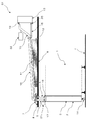
- FIG. 1 is a side view showing the configuration of the cooling system according to the first embodiment of the present invention.
- FIG. 2 is a top view showing the configuration of the cooling system according to the first embodiment of the present invention.
- the cooling system S1 according to the first embodiment of the present invention includes an evaporator 3, refrigerant vapor pipes 5, 15, refrigerant liquid pipes 6, 16, flexible pipes 10, 11, an inclined table 12, and a heat exchanger. 13, a pressure gauge 21, and a pressure regulator 22.
- a server rack 1 capable of storing a rack mount server computer (not shown) is installed on a seismic isolation floor 4.
- the rear door 2 of the server rack 1 is attached to the server rack 1 so as to be openable and closable by a mounting bracket 23 having a rotating shaft 24.
- the back door 2 houses the evaporator 3 and includes wheels 14.
- the cooling system S1 performs cooling using a refrigerant.
- the evaporator 3 absorbs the heat discharged from the server rack 1 by evaporating the refrigerant.
- the refrigerant (refrigerant vapor) that has become vapor by absorbing heat moves to the heat exchanger 13 via the refrigerant vapor pipe 5, the flexible pipe 10, and the refrigerant vapor pipe 15.
- the heat exchanger 13 condenses the refrigerant vapor by cooling the refrigerant vapor.
- the refrigerant (refrigerant liquid) condensed into a liquid moves to the evaporator 3 via the refrigerant liquid pipe 16, the flexible pipe 11 and the refrigerant liquid pipe 6.
- the evaporator 3 absorbs the heat discharged from the server rack 1.
- the refrigerant vapor pipe 5 and the refrigerant liquid pipe 6 are connected at one end to pipe ports 17 and 18 at the top of the evaporator 3, and the other end is fixed to the carriage 7.
- the carriage 7 includes wheels 8 that can move in any direction on a non-seismic isolation ceiling 9.
- the tilting table 12 has an inclined surface that increases on its upper surface as it approaches the other end from one end.
- One end of each of the refrigerant vapor pipe 15 and the refrigerant liquid pipe 16 is connected to pipe ports 19 and 20 of the heat exchanger 13.
- the flexible pipe 10 has one end connected to the refrigerant vapor pipe 5 and the other end connected to the refrigerant vapor pipe 15.
- the flexible pipe 11 has one end connected to the refrigerant liquid pipe 6 and the other end connected to the refrigerant liquid pipe 16.
- the flexible pipes 10 and 11 which are bendable are connected not to connect the refrigerant vapor pipes 5 and 15 and the refrigerant liquid pipes 6 and 16 at the shortest distance but to bend by having an extra length. ing.
- the flexible pipe 10 is placed on the tilt table 12 so as to become higher from the side connected to the refrigerant vapor pipe 5 toward the side connected to the refrigerant vapor pipe 15.
- the flexible pipe 11 is placed on the inclined base 12 so as to increase from the side connected to the refrigerant liquid pipe 6 toward the side connected to the refrigerant liquid pipe 16.
- the heat exchanger 13 is installed at a position where the piping ports 19 and 20 are higher than the piping ports 17 and 18, respectively.
- the flow path of the refrigerant vapor from the evaporator 3 to the heat exchanger 13 through the refrigerant vapor pipe 5, the flexible pipe 10, and the refrigerant vapor pipe 15 is in ascending order in which no reverse gradient exists in the middle. Kept on a gradient.
- the flow path of the refrigerant liquid from the heat exchanger 13 to the evaporator 3 via the refrigerant liquid pipe 16, the flexible pipe 11, and the refrigerant liquid pipe 6 is a downward forward gradient with no reverse gradient in the middle. To be kept.
- the pressure gauge 21 measures the pressure (atmospheric pressure) in the pipe. That is, the pressure gauge 21 measures the pressure of the refrigerant vapor.
- the pressure gauge 21 may be a mechanical type or an electronic type.
- the pressure gauge 21 may have a function of outputting the measured pressure value as an electrical signal.
- the pressure adjuster 22 adjusts the pressure in the piping to be within a specified range.
- the pressure regulator 22 may be a vacuum pump or an on-off valve.
- the defined range may be, for example, the saturated vapor pressure and the vicinity thereof.
- the pressure regulator 22 may automatically adjust the pressure in the pipe based on the pressure value indicated by the pressure gauge 21. For example, when the pressure gauge 21 indicates a value higher than a specified pressure, the pressure regulator 22 may reduce the pressure in the pipe.
- FIG. 3 is a top view showing a state in which the rear door 2 is open.
- the operation when the rear door 2 is opened and closed will be described with reference to FIGS.
- the rear door 2 can be opened and closed by rotating around the rotary shaft 24.
- the positions of the refrigerant vapor pipe 5 and the refrigerant liquid pipe 6 change. This misalignment is absorbed by the flexible pipes 10 and 11 being bent and stretched (ie, bent) due to the extra length and flexibility of the flexible pipes 10 and 11.
- the refrigerant vapor pipe 5 and the refrigerant liquid pipe 6 are fixed to a carriage 7 having wheels 8, even when the refrigerant vapor pipe 5 and the refrigerant liquid pipe 6 are moved according to the opening and closing of the rear door 2, they can be rotated without causing twisting. .
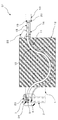
- FIG. 4 is a top view showing the range of movement of the rear door 2 when an earthquake occurs.
- FIG. 4 is a top view showing the range of movement of the rear door 2 when an earthquake occurs.
- the seismic isolation floor 4 mitigates the impact of seismic vibrations by the relative movement that occurs in response to the earthquake vibration.
- a movable range 30 shown in FIG. 4 indicates a movable range of the base isolation floor 4 with respect to the ceiling 9 when an earthquake occurs.
- the carriage 7 to which the refrigerant vapor pipe 5 and the refrigerant liquid pipe 6 are fixed can move smoothly on the ceiling 9 by the action of the wheels 8.
- the flexible pipes 10 and 11 are bent and stretched by the surplus length and flexibility of the flexible pipes 10 and 11, so that the displacement of the seismic isolation floor 4 and the ceiling 9 is absorbed.
- the cooling system S1 can prevent a decrease in cooling efficiency. This is because the flow paths of the refrigerant are kept in a forward gradient by placing the flexible pipes 10 and 11 on the inclined base 12. That is, the absence of a reverse gradient in the refrigerant flow path prevents the refrigerant from staying moving.
- the cooling system S1 allows the back door 2 to be opened and closed while maintaining the connection by the piping between the evaporator 3 and the heat exchanger 13. This is because the flexible pipes 10 and 11 can be bent and stretched by the surplus length and flexibility of the flexible pipes 10 and 11 to absorb the displacement of the pipes when the rear door 2 is opened and closed while maintaining the connection of the pipes. is there.
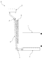
- FIG. 5 is a side view showing the configuration of the cooling system according to the second embodiment of the present invention.
- the cooling system S2 according to the second embodiment of the present invention includes an inclined plate 42 and support columns 40 and 41 instead of the inclined table 12 shown in FIG.
- the inclined plate 42 is suspended from the ceiling 9 by the columns 40 and 41 in an inclined state so as to become higher as it approaches the other end from one end.
- the overlapping description is abbreviate
- the configuration of the cooling system S2 shown in FIG. 5 is effective when the length of the refrigerant vapor pipe 5 and the refrigerant liquid pipe 6 is short and the possibility of pipe twisting due to movement is small.
- FIG. 6 is a side view showing the configuration of the cooling system according to the third embodiment of the present invention.
- a cooling system S3 according to the third embodiment of the present invention includes an evaporator 3, a flexible pipe 10, an inclined table 12, and a heat exchanger 13.
- the evaporator 3 is sometimes called a heat absorber.
- the flexible pipe 10 is sometimes referred to as a first flexible pipe.
- the tilting table 12 is sometimes called a mounting table.
- the heat exchanger 13 may be called a heat radiator.
- the evaporator 3 absorbs heat released from the server rack 1 by the refrigerant.
- the server rack 1 may be other equipment.
- the evaporator 3 is provided with a piping port 17.
- the piping port 17 may be referred to as a first piping port.
- the heat exchanger 13 cools the refrigerant.
- the heat exchanger 13 includes a piping port 19.
- the piping port 19 is located higher than the piping port 17.
- the piping port 19 may be referred to as a second piping port.
- the flexible piping 10 is connected to the piping port 17 and the piping port 19.
- the flexible pipe 10 is bendable and serves as a refrigerant flow path.
- the inclined base 12 has a surface that increases from one end to the other end. On this surface, the flexible pipe 10 is placed so as to increase from the side connected to the pipe port 17 toward the side connected to the pipe port 19.
- the cooling system S3 can prevent a decrease in cooling efficiency. This is because the flow path of the refrigerant is maintained at a forward gradient by placing the flexible pipe 10 on the inclined base 12. That is, the absence of a reverse gradient in the refrigerant flow path prevents the refrigerant from staying moving.
- the heat exchanger 13 in the first to third embodiments may be an air cooling type or a water cooling type cooling tower.
- a heat exchanger that cools the refrigerant used in the cooling systems S1 to S3 with another refrigerant may be used.
- the server rack 1 in the first to third embodiments may be another electronic device.
- the first to third embodiments describe examples in which the two slopes of the flexible pipes 10 and 11 are forward slopes, the present invention is not limited to this.
- the flexible pipe 10 connected to the cooling steam pipes 5 and 15 may have a forward slope
- the flexible pipe 11 connected to the coolant pipes 6 and 16 may be horizontal.
- the flexible pipes 10 and 11 of the first to third embodiments may be one.
- the flexible pipe has a pipe diameter that allows the liquid that becomes the refrigerant to be separated from the vapor in the pipe by gravity
- the flexible pipe has one end of the refrigerant liquid and the vapor, and the other end that separates the liquid and the vapor that becomes the refrigerant. Will be provided.
- the inclined plate 42 is suspended from the ceiling 9 by the columns 40 and 41, but may be suspended from other things. That is, the inclined plate 42 may be hung from another surface, member, or structure located above.
- the present invention has been described above using the above-described embodiment as an exemplary example. However, the present invention is not limited to the above-described embodiment. That is, the present invention can apply various modes that can be understood by those skilled in the art within the scope of the present invention. This application claims the priority on the basis of Japanese application Japanese Patent Application No. 2013-267091 for which it applied on December 25, 2013, and takes in those the indications of all here.
- the present invention can be used for a cooling device using a boiling cooling system in which heat is transported and released by a refrigerant vaporization and condensation cycle.
Landscapes
- Engineering & Computer Science (AREA)
- Physics & Mathematics (AREA)
- General Engineering & Computer Science (AREA)
- Thermal Sciences (AREA)
- Life Sciences & Earth Sciences (AREA)
- Sustainable Development (AREA)
- Mechanical Engineering (AREA)
- Microelectronics & Electronic Packaging (AREA)
- Theoretical Computer Science (AREA)
- Computer Hardware Design (AREA)
- General Physics & Mathematics (AREA)
- Human Computer Interaction (AREA)
- Cooling Or The Like Of Electrical Apparatus (AREA)
Abstract
[課題] 冷媒を用いる冷却システムの冷却効率の低下を防止する。[解決手段] 冷却システム(S3)は、配管口(17)を有し、サーバラック(1)から放出される熱を冷媒により吸熱する蒸発器(3)と、配管口(17)よりも高い位置に配管口(19)を有し、冷媒を冷却する熱交換器(13)と、配管口(17)と配管口(19)に接続され、冷媒の流路となる屈曲自在なフレキシブル配管(10)と、一方の端部から他方の端部に近づくに従って高くなる面を有し、当該面には、配管口(17)に接続された側から配管口(19)に接続された側に近づくに従って高くなるようにフレキシブル配管(10)が載置される載置台(12)とを備える。
Description
本発明は、熱を発生する機器を冷却する技術に関し、特に冷却システムおよび電子機器に関する。
サーバなどの熱を発生する機器の運用においては、機器を効率的に冷却することが求められる。
特許文献1記載の冷却システムは、サーバから排出される熱を、蒸発器を流れる冷媒液が蒸発することにより吸熱する。そして、係る冷却システムは、加熱された冷媒蒸気を、蒸発器より高所に設置された冷却塔において凝縮することにより、吸熱した熱を放出する。
特許文献1記載の冷却システムは、蒸発器と冷却塔を接続する配管の一部にフレキシブル配管を備えることにより、蒸発器が移動することを可能にする。
上述した特許文献1記載の冷却システムにおいては、冷却塔を蒸発器よりも高所に配置することにより、気体あるいは液体となっている冷媒が冷却塔と蒸発器の間を効率的に移動することを可能にする。しかしながら、冷媒の流路となる配管に逆勾配の部分が存在する場合、逆勾配の部分において冷媒の移動が滞るために、冷却効率が低下するという問題がある。例えば、特許文献1の図5に示されるフレキシブル配管のように、フレキシブル配管の一部がループ状になっている場合がこれに該当する。
本発明は、上述した課題を解決するための技術を提供することを主たる目的とする。
上記目的を達成する本発明に係る冷却システムは、
第1の配管口を有し、機器から放出される熱を冷媒により吸熱する吸熱器と、
前記第1の配管口よりも高い位置に第2の配管口を有し、前記冷媒を冷却する放熱器と、
一端が前記第1の配管口に接続され、他端が前記第2の配管口に接続され、前記冷媒の流路となる、屈曲自在な第1のフレキシブル配管と、
一方の端部から他方の端部に近づくに従って鉛直方向に高くなる面を有し、当該面には、前記第1の配管口に接続された側から前記第2の配管口に接続された側に近づくに従って鉛直方向に高くなるように前記第1のフレキシブル配管が載置される載置台とを備える。
第1の配管口を有し、機器から放出される熱を冷媒により吸熱する吸熱器と、
前記第1の配管口よりも高い位置に第2の配管口を有し、前記冷媒を冷却する放熱器と、
一端が前記第1の配管口に接続され、他端が前記第2の配管口に接続され、前記冷媒の流路となる、屈曲自在な第1のフレキシブル配管と、
一方の端部から他方の端部に近づくに従って鉛直方向に高くなる面を有し、当該面には、前記第1の配管口に接続された側から前記第2の配管口に接続された側に近づくに従って鉛直方向に高くなるように前記第1のフレキシブル配管が載置される載置台とを備える。
また、上記目的を達成する本発明に係る電子機器は、上述の冷却システムを備える。
本発明によれば、冷媒を用いる冷却システムの冷却効率の低下を防止することができる。
次に、本発明の実施の形態について図面を参照して詳細に説明する。
[第1の実施形態]
図1は、本発明の第1の実施形態に係る冷却システムの構成を表す側面図である。また、図2は、本発明の第1の実施形態に係る冷却システムの構成を表す上面図である。本発明の第1の実施形態に係る冷却システムS1は、蒸発器3と、冷媒蒸気配管5,15と、冷媒液配管6,16と、フレキシブル配管10,11と、傾斜台12と、熱交換機13と、圧力計21と、圧力調整器22とを備える。
図1は、本発明の第1の実施形態に係る冷却システムの構成を表す側面図である。また、図2は、本発明の第1の実施形態に係る冷却システムの構成を表す上面図である。本発明の第1の実施形態に係る冷却システムS1は、蒸発器3と、冷媒蒸気配管5,15と、冷媒液配管6,16と、フレキシブル配管10,11と、傾斜台12と、熱交換機13と、圧力計21と、圧力調整器22とを備える。
例えばラックマウント型サーバコンピュータ(不図示)を収納可能なサーバラック1は、免震床4の上に設置されている。サーバラック1の背面扉2は、回転軸24を有する取付金具23によって、サーバラック1に開閉自在に取り付けられている。また、背面扉2は、蒸発器3を収納しており、車輪14を備えている。
冷却システムS1は、冷媒を用いて冷却を行う。蒸発器3は、冷媒を蒸発させることにより、サーバラック1が排出する熱を吸熱する。吸熱することにより蒸気となった冷媒(冷媒蒸気)は、冷媒蒸気配管5、フレキシブル配管10および冷媒蒸気配管15を経由して熱交換器13に移動する。熱交換器13は、冷媒蒸気を冷却することにより、冷媒蒸気を凝縮する。凝縮して液体となった冷媒(冷媒液)は、冷媒液配管16、フレキシブル配管11および冷媒液配管6を経由して蒸発器3に移動する。そして、再び、蒸発器3はサーバラック1が排出する熱を吸熱する。
冷媒蒸気配管5および冷媒液配管6は、それらの一端が蒸発器3の上部にある配管口17,18に接続され、他方の一端の付近が台車7に固定されている。台車7は、非免震の天井9の上をあらゆる方向に移動可能な車輪8を備えている。
天井9の上には傾斜台12が設置されている。傾斜台12は、その上面に、一方の端部から他方の端部に近づくに従って高くなる傾斜面を備えている。
冷媒蒸気配管15および冷媒液配管16は、それらの一端が、熱交換器13が有する配管口19,20に接続されている。
フレキシブル配管10は、その一端が冷媒蒸気配管5に接続され、他方の一端が冷媒蒸気配管15に接続されている。また、フレキシブル配管11は、その一端が冷媒液配管6に接続され、他方の一端が冷媒液配管16に接続されている。ここで、屈曲自在であるフレキシブル配管10,11は、冷媒蒸気配管5,15と冷媒液配管6,16を最短距離で接続するのではなく、余長を持つことによりたわみが生じるように接続している。
フレキシブル配管10は、冷媒蒸気配管5に接続された側から冷媒蒸気配管15に接続された側に近づくに従って高くなるように傾斜台12の上に載置されている。同様に、フレキシブル配管11は、冷媒液配管6に接続された側から冷媒液配管16に接続された側に近づくに従って高くなるように傾斜台12の上に載置されている。
熱交換器13は、配管口19,20が、それぞれ配管口17,18よりも高くなるような位置に設置されている。
以上の構成により、蒸発器3から、冷媒蒸気配管5、フレキシブル配管10および冷媒蒸気配管15を介して、熱交換器13に至る冷媒蒸気の流路が、途中に逆勾配が存在しない上りの順勾配に保たれる。また同様に、熱交換器13から、冷媒液配管16、フレキシブル配管11および冷媒液配管6を介して、蒸発器3に至る冷媒液の流路が、途中に逆勾配が存在しない下りの順勾配に保たれる。
圧力計21は、配管内の圧力(気圧)を計測する。すなわち、圧力計21は、冷媒蒸気の圧力を計測する。圧力計21は、機械式でもよいし、電子式でもよい。圧力計21は、計測した圧力の値を電気信号として出力する機能を有していてもよい。
圧力調整器22は、配管内の圧力が規定された範囲になるように調整する。圧力調整器22は、真空ポンプでもよいし、開閉弁でもよい。規定された範囲とは、例えば、飽和蒸気圧およびその近傍であってもよい。配管内の圧力が飽和蒸気圧およびその近傍に保たれることにより、冷却システムS1の冷却効率が低下することが防止される。
圧力調整器22は、圧力計21が示す圧力の値に基づいて配管内の圧力を自動的に調節してもよい。例えば、圧力計21が規定の圧力より高い値を示していた場合、圧力調整器22は、配管内の圧力を低下させてもよい。
図3は、背面扉2が開いている状態を示す上面図である。以下、図2,3を参照して、背面扉2開閉時の動作について説明する。
背面扉2は、回転軸24を中心に回転することにより、開閉可能である。背面扉2の開閉に従い、冷媒蒸気配管5および冷媒液配管6の位置が変動する。この位置のずれは、フレキシブル配管10,11が、自身が有する余長および柔軟性によって曲げ伸ばしする(即ち、屈曲する)ことにより、吸収される。このことにより、蒸発器3と熱交換器13の間の配管による接続を維持したまま、背面扉2を開閉することが可能である。
冷媒蒸気配管5および冷媒液配管6は、車輪8を備える台車7に固定されているため、背面扉2の開閉に従って移動した際にも、捻れを生じる事なしに回転移動することが可能である。
フレキシブル配管10,11は、傾斜台12の上に載置されているため、背面扉2の開閉に従って移動した際にも、順勾配を保つことが可能である。
図4は、地震発生時における背面扉2の移動範囲を示す上面図である。以下、図4を参照して、地震発生時の動作について説明する。
免震床4は、地震の震動に応じて生じる相対的な動作によって、地震振動の衝撃を緩和する。このことにより、地震発生時においては、免震床4と非免震の天井9との間で、免震床4の移動に伴う位置のずれが発生する。図4に示す可動範囲30は、地震発生時における、天井9に対する免震床4の可動範囲を示す。地震発生時においては、冷媒蒸気配管5と冷媒液配管6が固定されている台車7は、車輪8の働きにより、天井9上をなめらかに移動することができる。このとき、フレキシブル配管10,11が、自身が有する余長および柔軟性によって曲げ伸ばしすることにより、免震床4と天井9との位置のずれが吸収される。このことにより、地震発生時においても、蒸発器3と熱交換器13の間の配管による接続を維持することが可能である。
冷媒蒸気配管5および冷媒液配管6は、車輪8を備える台車7に固定されているため、地震発生時においても、捻れの発生を防止することが可能である。
フレキシブル配管10,11は、傾斜台12の上に載置されているため、地震の震動に伴って移動した際にも、一定の順勾配を保つことが可能である。
以上のように、本発明の第1の実施形態に係る冷却システムS1は、冷却効率の低下を防止することができる。なぜならば、フレキシブル配管10,11が傾斜台12に載置されることにより、冷媒の流路が順勾配に保たれるからである。すなわち、冷媒の流路に逆勾配が存在しないことにより、冷媒の移動の滞留が防止されるからである。
また、本発明の第1の実施形態に係る冷却システムS1は、蒸発器3と熱交換器13の間の配管による接続を維持したまま、背面扉2を開閉することを可能にする。なぜならば、フレキシブル配管10,11が、自身が有する余長および柔軟性によって曲げ伸ばし可能であることにより、配管の接続を維持したまま、背面扉2開閉時における配管の位置ずれを吸収するからである。
また、同様の理由により、本発明の第1の実施形態に係る冷却システムS1は、免震床4と天井9の位置ずれを吸収することにより、地震発生時においても蒸発器3と熱交換器13の間の配管による接続を維持することができる。
[第2の実施形態]
次に、本発明の第2の実施の形態を説明する。以下の説明では、第1の実施形態と同様な構成については同一の参照番号を付与することにより、重複する説明を省略する。
次に、本発明の第2の実施の形態を説明する。以下の説明では、第1の実施形態と同様な構成については同一の参照番号を付与することにより、重複する説明を省略する。
図5は、本発明の第2の実施形態に係る冷却システムの構成を表す側面図である。本発明の第2の実施形態に係る冷却システムS2は、図1に示す傾斜台12の代わりに、傾斜板42と支柱40,41とを備える。傾斜板42は、支柱40,41によって、一方の端部から他方の端部に近づくに従って高くなるように傾斜した状態で天井9から吊り下げられている。第1の実施形態と同様の他の構成については、同一の参照番号を付与することにより、重複する説明を省略する。
図5に示す冷却システムS2の構成は、冷媒蒸気配管5と冷媒液配管6の長さが短いために、移動に伴う配管捻れの可能性が少ない場合に有効である。
本発明の第2の実施形態に係る冷却システムS2においても、第1の実施形態に係るシステムS1と同様の効果を奏することができる。
[第3の実施形態]
次に、本発明の第3の実施の形態を説明する。
次に、本発明の第3の実施の形態を説明する。
図6は、本発明の第3の実施形態に係る冷却システムの構成を表す側面図である。本発明の第3の実施形態に係る冷却システムS3は、蒸発器3と、フレキシブル配管10と、傾斜台12と、熱交換機13とを備える。
蒸発器3は、吸熱器と呼ばれることもある。フレキシブル配管10は、第1のフレキシブル配管と呼ばれることもある。傾斜台12は、載置台と呼ばれることもある。熱交換機13は、放熱器と呼ばれることもある。
蒸発器3は、サーバラック1から放出される熱を冷媒により吸熱する。サーバラック1は、他の機器でもよい。
蒸発器3は、配管口17を備えている。配管口17は、第1の配管口と呼ばれることもある。
熱交換器13は、冷媒を冷却する。熱交換器13は、配管口19を備えている。配管口19は、配管口17よりも高い位置にある。配管口19は、第2の配管口と呼ばれることもある。
フレキシブル配管10は、配管口17と配管口19に接続されている。フレキシブル配管10は、屈曲自在であり、冷媒の流路となる。
傾斜台12は、一方の端部から他方の端部に近づくに従って高くなる面を有している。この面には、配管口17に接続された側から配管口19に接続された側に近づくに従って高くなるようにフレキシブル配管10が載置される。
以上のように、本発明の第3の実施形態に係る冷却システムS3は、冷却効率の低下を防止することができる。なぜならば、フレキシブル配管10が傾斜台12に載置されることにより、冷媒の流路が順勾配に保たれるからである。すなわち、冷媒の流路に逆勾配が存在しないことにより、冷媒の移動の滞留が防止されるからである。
第1~第3の実施形態における熱交換器13は、空冷式や水冷式の冷却塔でもよい。あるいは、冷却システムS1~S3で使用する冷媒を、他の冷媒により冷却する熱交換器でもよい。
第1~第3の実施形態におけるサーバラック1は、他の電子機器でもよい。なお、第1~第3の実施形態は、フレキシブル配管10,11の2本の傾斜が順勾配となる例を記載しているが、これに限られるものではない。例えば、冷却蒸気配管5,15に接続されるフレキシブル配管10が順勾配で、冷却液配管6,16に接続されるフレキシブル配管11は、水平であってもよい。また、第1~第3の実施形態のフレキシブル配管10、11の2本を1本にしてもよい。その場合、フレキシブル配管は、冷媒となる液体が重力により管内で蒸気と分離できる管径を有し、フレキシブル配管の一端に冷媒液体と蒸気の合流部、他端に冷媒となる液体と蒸気の分離部を設けることになる。
第2の実施形態において、傾斜板42は、支柱40,41によって天井9から吊り下げられていたが、他のものから吊り下げられてもよい。すなわち、傾斜板42は、上方に位置する、他の面や、部材や、構造物から吊り下げられてもよい。
以上、上述した実施形態を模範的な例として本発明を説明した。しかしながら、本発明は、上述した実施形態には限定されない。即ち、本発明は、本発明のスコープ内において、当業者が理解し得る様々な態様を適用することができる。
この出願は、2013年12月25日に出願された日本出願特願2013-267091を基礎とする優先権を主張し、その開示の全てをここに取り込む。
以上、上述した実施形態を模範的な例として本発明を説明した。しかしながら、本発明は、上述した実施形態には限定されない。即ち、本発明は、本発明のスコープ内において、当業者が理解し得る様々な態様を適用することができる。
この出願は、2013年12月25日に出願された日本出願特願2013-267091を基礎とする優先権を主張し、その開示の全てをここに取り込む。
本発明は、冷媒の気化と凝縮のサイクルによって熱の輸送および放熱を行う沸騰冷却方式を用いた冷却装置に使用することができる。
S1,S2,S3 冷却システム
1 サーバラック
2 背面扉
3 蒸発器
4 免震床
5,15 冷媒蒸気配管
6,16 冷媒液配管
7 台車
8,14 車輪
9 天井
10,11 フレキシブル配管
12 傾斜台
13 熱交換器
17,18,19,20 配管口
21 圧力計
22 圧力調整器
23 取付金具
24 回転軸
30 可動範囲
40,41 支柱
42 傾斜板
1 サーバラック
2 背面扉
3 蒸発器
4 免震床
5,15 冷媒蒸気配管
6,16 冷媒液配管
7 台車
8,14 車輪
9 天井
10,11 フレキシブル配管
12 傾斜台
13 熱交換器
17,18,19,20 配管口
21 圧力計
22 圧力調整器
23 取付金具
24 回転軸
30 可動範囲
40,41 支柱
42 傾斜板
Claims (8)
- 第1の配管口を有し、機器から放出される熱を冷媒により吸熱する吸熱器と、
前記第1の配管口よりも高い位置に第2の配管口を有し、前記冷媒を冷却する放熱器と、
一端が前記第1の配管口に接続され、他端が前記第2の配管口に接続され、前記冷媒の流路となる、屈曲自在な第1のフレキシブル配管と、
一方の端部から他方の端部に近づくに従って鉛直方向に高くなる面を有し、当該面には、前記第1の配管口に接続された側から前記第2の配管口に接続された側に近づくに従って鉛直方向に高くなるように前記第1のフレキシブル配管が載置される載置台と、
を備える冷却システム。 - 前記吸熱器は、第3の配管口をさらに有し、前記冷媒が蒸発することにより前記機器から放出される熱を吸熱し、
前記放熱器は、前記第3の配管口よりも高い位置に第4の配管口をさらに有し、蒸発した前記冷媒を冷却することにより凝縮し、
一端が前記第3の配管口に接続され、他端が前記第4の配管口に接続され、前記冷媒の流路となる、屈曲自在な第2のフレキシブル配管をさらに備え、
前記載置台の前記面には、前記第3の配管口に接続された側から前記第4の配管口に接続された側に近づくに従って鉛直方向に高くなるように前記第2のフレキシブル配管が載置され、
前記第1のフレキシブル配管は、前記吸熱器にて蒸発した前記冷媒が前記放熱器に移動する流路であり、
前記第2のフレキシブル配管は、前記放熱器にて凝縮した前記冷媒が前記吸熱器に移動する流路である
請求項1に記載の冷却システム。 - 前記第1および第2のフレキシブル配管は、前記載置台に載置された状態においてたわみを有し、前記吸熱器の移動に応じて屈曲自在である請求項1または2に記載の冷却システム。
- 前記第1および第2のフレキシブル配管の一端が固定され、前記吸熱器の移動に応じて移動可能である台車をさらに備える請求項1乃至3のいずれかに記載の冷却システム。
- 前記載置台は、前記吸熱器上方に位置する面に配置される請求項1乃至4のいずれかに記載の冷却システム。
- 前記載置台は、前記吸熱器上方から釣支される請求項1乃至4のいずれかに記載の冷却システム。
- 蒸発した前記冷媒の圧力を計測する圧力計と、計測した圧力に基づいて前記圧力を規定状態に調節する圧力調整器とをさらに備えた請求項2乃至6のいずれかに記載の冷却システム。
- 請求項1乃至8のいずれかに記載の冷却システムを備えた電子機器。
Priority Applications (2)
| Application Number | Priority Date | Filing Date | Title |
|---|---|---|---|
| US15/105,950 US10408545B2 (en) | 2013-12-25 | 2014-12-02 | Cooling system and electronic equipment |
| EP14873921.2A EP3089571B1 (en) | 2013-12-25 | 2014-12-02 | Cooling system and electronic apparatus |
Applications Claiming Priority (2)
| Application Number | Priority Date | Filing Date | Title |
|---|---|---|---|
| JP2013267091A JP5986064B2 (ja) | 2013-12-25 | 2013-12-25 | 冷却システムおよび電子機器 |
| JP2013-267091 | 2013-12-25 |
Publications (1)
| Publication Number | Publication Date |
|---|---|
| WO2015097992A1 true WO2015097992A1 (ja) | 2015-07-02 |
Family
ID=53477904
Family Applications (1)
| Application Number | Title | Priority Date | Filing Date |
|---|---|---|---|
| PCT/JP2014/006021 Ceased WO2015097992A1 (ja) | 2013-12-25 | 2014-12-02 | 冷却システムおよび電子機器 |
Country Status (5)
| Country | Link |
|---|---|
| US (1) | US10408545B2 (ja) |
| EP (1) | EP3089571B1 (ja) |
| JP (1) | JP5986064B2 (ja) |
| TW (1) | TWI639378B (ja) |
| WO (1) | WO2015097992A1 (ja) |
Families Citing this family (63)
| Publication number | Priority date | Publication date | Assignee | Title |
|---|---|---|---|---|
| JP6720584B2 (ja) * | 2016-03-07 | 2020-07-08 | 富士通株式会社 | 嵌合ユニット及び電子機器 |
| JP6628327B2 (ja) * | 2017-10-20 | 2020-01-08 | Necプラットフォームズ株式会社 | サーバ |
| WO2020102090A1 (en) * | 2018-11-16 | 2020-05-22 | TMGCore, LLC | Liquid immersion cooling platform |
| US11467605B2 (en) | 2019-04-10 | 2022-10-11 | Deere & Company | Zonal machine control |
| US11957072B2 (en) | 2020-02-06 | 2024-04-16 | Deere & Company | Pre-emergence weed detection and mitigation system |
| US11079725B2 (en) | 2019-04-10 | 2021-08-03 | Deere & Company | Machine control using real-time model |
| US11589509B2 (en) | 2018-10-26 | 2023-02-28 | Deere & Company | Predictive machine characteristic map generation and control system |
| US11672203B2 (en) | 2018-10-26 | 2023-06-13 | Deere & Company | Predictive map generation and control |
| US11240961B2 (en) | 2018-10-26 | 2022-02-08 | Deere & Company | Controlling a harvesting machine based on a geo-spatial representation indicating where the harvesting machine is likely to reach capacity |
| US11653588B2 (en) | 2018-10-26 | 2023-05-23 | Deere & Company | Yield map generation and control system |
| US12069978B2 (en) | 2018-10-26 | 2024-08-27 | Deere & Company | Predictive environmental characteristic map generation and control system |
| US11178818B2 (en) | 2018-10-26 | 2021-11-23 | Deere & Company | Harvesting machine control system with fill level processing based on yield data |
| US11641800B2 (en) | 2020-02-06 | 2023-05-09 | Deere & Company | Agricultural harvesting machine with pre-emergence weed detection and mitigation system |
| US12408308B2 (en) | 2018-11-16 | 2025-09-02 | Modine LLC | Hydrofire rods for liquid immersion cooling platform |
| US11234366B2 (en) | 2019-04-10 | 2022-02-01 | Deere & Company | Image selection for machine control |
| US12225846B2 (en) | 2020-02-06 | 2025-02-18 | Deere & Company | Machine control using a predictive map |
| US12035648B2 (en) | 2020-02-06 | 2024-07-16 | Deere & Company | Predictive weed map generation and control system |
| US12329148B2 (en) | 2020-02-06 | 2025-06-17 | Deere & Company | Predictive weed map and material application machine control |
| US11477940B2 (en) | 2020-03-26 | 2022-10-25 | Deere & Company | Mobile work machine control based on zone parameter modification |
| US12178158B2 (en) | 2020-10-09 | 2024-12-31 | Deere & Company | Predictive map generation and control system for an agricultural work machine |
| US11849671B2 (en) | 2020-10-09 | 2023-12-26 | Deere & Company | Crop state map generation and control system |
| US11650587B2 (en) | 2020-10-09 | 2023-05-16 | Deere & Company | Predictive power map generation and control system |
| US11844311B2 (en) | 2020-10-09 | 2023-12-19 | Deere & Company | Machine control using a predictive map |
| US11927459B2 (en) | 2020-10-09 | 2024-03-12 | Deere & Company | Machine control using a predictive map |
| US11895948B2 (en) | 2020-10-09 | 2024-02-13 | Deere & Company | Predictive map generation and control based on soil properties |
| US11635765B2 (en) | 2020-10-09 | 2023-04-25 | Deere & Company | Crop state map generation and control system |
| US12013245B2 (en) | 2020-10-09 | 2024-06-18 | Deere & Company | Predictive map generation and control system |
| US11871697B2 (en) | 2020-10-09 | 2024-01-16 | Deere & Company | Crop moisture map generation and control system |
| US11946747B2 (en) | 2020-10-09 | 2024-04-02 | Deere & Company | Crop constituent map generation and control system |
| US11825768B2 (en) | 2020-10-09 | 2023-11-28 | Deere & Company | Machine control using a predictive map |
| US11983009B2 (en) | 2020-10-09 | 2024-05-14 | Deere & Company | Map generation and control system |
| US11474523B2 (en) | 2020-10-09 | 2022-10-18 | Deere & Company | Machine control using a predictive speed map |
| US12419220B2 (en) | 2020-10-09 | 2025-09-23 | Deere & Company | Predictive map generation and control system |
| US12069986B2 (en) | 2020-10-09 | 2024-08-27 | Deere & Company | Map generation and control system |
| US11864483B2 (en) | 2020-10-09 | 2024-01-09 | Deere & Company | Predictive map generation and control system |
| US11675354B2 (en) | 2020-10-09 | 2023-06-13 | Deere & Company | Machine control using a predictive map |
| US11845449B2 (en) | 2020-10-09 | 2023-12-19 | Deere & Company | Map generation and control system |
| US11849672B2 (en) | 2020-10-09 | 2023-12-26 | Deere & Company | Machine control using a predictive map |
| US11874669B2 (en) | 2020-10-09 | 2024-01-16 | Deere & Company | Map generation and control system |
| US11592822B2 (en) | 2020-10-09 | 2023-02-28 | Deere & Company | Machine control using a predictive map |
| US11727680B2 (en) | 2020-10-09 | 2023-08-15 | Deere & Company | Predictive map generation based on seeding characteristics and control |
| US12386354B2 (en) | 2020-10-09 | 2025-08-12 | Deere & Company | Predictive power map generation and control system |
| US11711995B2 (en) | 2020-10-09 | 2023-08-01 | Deere & Company | Machine control using a predictive map |
| US11889788B2 (en) | 2020-10-09 | 2024-02-06 | Deere & Company | Predictive biomass map generation and control |
| US12550802B2 (en) | 2020-10-08 | 2026-02-17 | Deere & Company | Predictive machine characteristic map generation and control system |
| US12422847B2 (en) | 2020-10-09 | 2025-09-23 | Deere & Company | Predictive agricultural model and map generation |
| US11889787B2 (en) | 2020-10-09 | 2024-02-06 | Deere & Company | Predictive speed map generation and control system |
| US12250905B2 (en) | 2020-10-09 | 2025-03-18 | Deere & Company | Machine control using a predictive map |
| US12127500B2 (en) | 2021-01-27 | 2024-10-29 | Deere & Company | Machine control using a map with regime zones |
| US12229886B2 (en) | 2021-10-01 | 2025-02-18 | Deere & Company | Historical crop state model, predictive crop state map generation and control system |
| US12310286B2 (en) | 2021-12-14 | 2025-05-27 | Deere & Company | Crop constituent sensing |
| US12302791B2 (en) | 2021-12-20 | 2025-05-20 | Deere & Company | Crop constituents, predictive mapping, and agricultural harvester control |
| US12245549B2 (en) | 2022-01-11 | 2025-03-11 | Deere & Company | Predictive response map generation and control system |
| US12520759B2 (en) | 2022-01-26 | 2026-01-13 | Deere & Company | Systems and methods for predicting material dynamics |
| US12082531B2 (en) | 2022-01-26 | 2024-09-10 | Deere & Company | Systems and methods for predicting material dynamics |
| CN217509346U (zh) * | 2022-03-16 | 2022-09-27 | 广运机械工程股份有限公司 | 热交换系统 |
| US12295288B2 (en) | 2022-04-05 | 2025-05-13 | Deere &Company | Predictive machine setting map generation and control system |
| US12058951B2 (en) | 2022-04-08 | 2024-08-13 | Deere & Company | Predictive nutrient map and control |
| US12582035B2 (en) | 2022-04-08 | 2026-03-24 | Deere & Company | Systems and methods for predictive power requirements and control |
| US12298767B2 (en) | 2022-04-08 | 2025-05-13 | Deere & Company | Predictive material consumption map and control |
| US12358493B2 (en) | 2022-04-08 | 2025-07-15 | Deere & Company | Systems and methods for predictive power requirements and control |
| US12284934B2 (en) | 2022-04-08 | 2025-04-29 | Deere & Company | Systems and methods for predictive tractive characteristics and control |
| CN115426862A (zh) * | 2022-10-18 | 2022-12-02 | 上海新近纪智能科技有限公司 | 基于重力热管的服务器散热系统 |
Citations (8)
| Publication number | Priority date | Publication date | Assignee | Title |
|---|---|---|---|---|
| JPH02225892A (ja) * | 1989-02-27 | 1990-09-07 | Hitachi Plant Eng & Constr Co Ltd | 可撓管サポート装置 |
| JPH09256612A (ja) * | 1996-03-19 | 1997-09-30 | Meidensha Corp | 免震建屋用フレキシブル管のサポート構造 |
| JPH1136425A (ja) * | 1997-07-18 | 1999-02-09 | Toyo Tire & Rubber Co Ltd | 排水配管における変位吸収用可撓性ホースの支持装置 |
| JP2002134664A (ja) * | 2000-10-20 | 2002-05-10 | Hitachi Ltd | 半導体冷却装置及びその制御方法 |
| JP2004270751A (ja) * | 2003-03-06 | 2004-09-30 | Fujita Corp | 免震構造物用配管構造 |
| JP2009123212A (ja) * | 2007-11-14 | 2009-06-04 | Internatl Business Mach Corp <Ibm> | エア/液体熱交換器を用いて電子機器ラックの冷却を促進する装置、及びこれを含む電子機器システム及びデータ・センタ |
| JP2011165707A (ja) | 2010-02-04 | 2011-08-25 | Hitachi Plant Technologies Ltd | 電子機器の冷却システム |
| JP2011247573A (ja) * | 2010-04-26 | 2011-12-08 | Gac Corp | 冷房システム |
Family Cites Families (30)
| Publication number | Priority date | Publication date | Assignee | Title |
|---|---|---|---|---|
| US5123479A (en) * | 1991-07-11 | 1992-06-23 | Conserve Resources, Inc. | Rotary heat exchanger of improved effectiveness |
| FR2725265B1 (fr) * | 1994-09-30 | 1996-12-13 | Grandi Rene Vincent | Dispositif de regulation et de transfert de fluides frigorifiques ou caloriques pour conteneurs de transport |
| JPH08338567A (ja) * | 1995-06-12 | 1996-12-24 | Sumitomo Kinzoku Plantec Kk | ガス配管の埋設工法 |
| JP3382798B2 (ja) * | 1996-11-13 | 2003-03-04 | 株式会社アカギ | 複数配管用サドル |
| JPH10288281A (ja) * | 1997-04-14 | 1998-10-27 | Ishikawajima Harima Heavy Ind Co Ltd | 配管支持装置 |
| US6257324B1 (en) * | 1998-06-30 | 2001-07-10 | Denso Corporation | Cooling apparatus boiling and condensing refrigerant |
| JP2002206880A (ja) * | 2001-01-10 | 2002-07-26 | Denso Corp | 沸騰冷却装置 |
| JP4657481B2 (ja) * | 2001-03-29 | 2011-03-23 | 株式会社ケーブイケー | 配管支持具 |
| JP2003125509A (ja) * | 2001-10-10 | 2003-04-25 | Kansai Electric Power Co Inc:The | 管 枕 |
| JP2004172021A (ja) * | 2002-11-21 | 2004-06-17 | Sumitomo Wiring Syst Ltd | プロテクタへのワイヤハーネス挿通方法および装置 |
| US6840311B2 (en) * | 2003-02-25 | 2005-01-11 | Delphi Technologies, Inc. | Compact thermosiphon for dissipating heat generated by electronic components |
| JP4277312B2 (ja) * | 2003-11-25 | 2009-06-10 | ツインバード工業株式会社 | サーモサイフォン |
| CN100491888C (zh) * | 2005-06-17 | 2009-05-27 | 富准精密工业(深圳)有限公司 | 环路式热交换装置 |
| JP2009134531A (ja) * | 2007-11-30 | 2009-06-18 | Sanyo Electric Co Ltd | 電子機器冷却システム |
| US7660116B2 (en) * | 2008-04-21 | 2010-02-09 | International Business Machines Corporation | Rack with integrated rear-door heat exchanger |
| US20090260384A1 (en) * | 2008-04-21 | 2009-10-22 | International Business Machines Corporation | Coolant Distribution System For A Rack Having A Rear-Door Heat Exchanger |
| FR2931961B1 (fr) * | 2008-06-02 | 2010-06-11 | Bull Sas | Dispositif de refroidissement d'une baie informatique et installation informatique comportant un tel dispositif |
| US20100059201A1 (en) | 2008-09-11 | 2010-03-11 | Sun Microsystems, Inc. | Liquid cooled rack with compliant heat exchanger support structure |
| JP5468315B2 (ja) * | 2009-06-23 | 2014-04-09 | 東亜建設工業株式会社 | 削孔位置計測方法およびシステム |
| JP5621225B2 (ja) | 2009-08-17 | 2014-11-12 | パナソニック株式会社 | 沸騰冷却装置 |
| US8077462B2 (en) * | 2009-09-02 | 2011-12-13 | International Business Machines Corporation | Stress relieved hose routing to liquid-cooled electronics rack door |
| JP5929754B2 (ja) * | 2010-03-30 | 2016-06-08 | 日本電気株式会社 | 電子機器排気の冷却装置 |
| JP5387523B2 (ja) * | 2010-07-01 | 2014-01-15 | 株式会社デンソー | 冷却装置 |
| US20140345829A1 (en) | 2011-05-27 | 2014-11-27 | Aavid Thermalloy, Llc | Thermal Transfer Device with Reduced Vertical Profile |
| JP2013088031A (ja) * | 2011-10-18 | 2013-05-13 | Hitachi Plant Technologies Ltd | 冷却システムとその制御方法 |
| JP6237761B2 (ja) * | 2013-02-26 | 2017-11-29 | 日本電気株式会社 | 電子機器冷却システム及び電子機器冷却システムの製造方法 |
| US10182517B2 (en) * | 2013-11-20 | 2019-01-15 | Nec Corporation | Electronic apparatus enclosure device and electronic apparatus cooling system |
| CN104567175B (zh) * | 2014-12-15 | 2016-11-23 | 青岛海尔股份有限公司 | 半导体制冷冰箱 |
| JP6034465B1 (ja) * | 2015-10-15 | 2016-11-30 | Necプラットフォームズ株式会社 | 冷却装置及び冷却システム |
| DE102017110102A1 (de) * | 2017-05-10 | 2018-11-15 | Friedhelm Meyer | Kältegerät mit Temperaturerfassungsmittel |
-
2013
- 2013-12-25 JP JP2013267091A patent/JP5986064B2/ja active Active
-
2014
- 2014-12-02 WO PCT/JP2014/006021 patent/WO2015097992A1/ja not_active Ceased
- 2014-12-02 US US15/105,950 patent/US10408545B2/en active Active
- 2014-12-02 EP EP14873921.2A patent/EP3089571B1/en active Active
- 2014-12-18 TW TW103144217A patent/TWI639378B/zh active
Patent Citations (8)
| Publication number | Priority date | Publication date | Assignee | Title |
|---|---|---|---|---|
| JPH02225892A (ja) * | 1989-02-27 | 1990-09-07 | Hitachi Plant Eng & Constr Co Ltd | 可撓管サポート装置 |
| JPH09256612A (ja) * | 1996-03-19 | 1997-09-30 | Meidensha Corp | 免震建屋用フレキシブル管のサポート構造 |
| JPH1136425A (ja) * | 1997-07-18 | 1999-02-09 | Toyo Tire & Rubber Co Ltd | 排水配管における変位吸収用可撓性ホースの支持装置 |
| JP2002134664A (ja) * | 2000-10-20 | 2002-05-10 | Hitachi Ltd | 半導体冷却装置及びその制御方法 |
| JP2004270751A (ja) * | 2003-03-06 | 2004-09-30 | Fujita Corp | 免震構造物用配管構造 |
| JP2009123212A (ja) * | 2007-11-14 | 2009-06-04 | Internatl Business Mach Corp <Ibm> | エア/液体熱交換器を用いて電子機器ラックの冷却を促進する装置、及びこれを含む電子機器システム及びデータ・センタ |
| JP2011165707A (ja) | 2010-02-04 | 2011-08-25 | Hitachi Plant Technologies Ltd | 電子機器の冷却システム |
| JP2011247573A (ja) * | 2010-04-26 | 2011-12-08 | Gac Corp | 冷房システム |
Non-Patent Citations (1)
| Title |
|---|
| See also references of EP3089571A4 |
Also Published As
| Publication number | Publication date |
|---|---|
| JP5986064B2 (ja) | 2016-09-06 |
| EP3089571A4 (en) | 2017-07-26 |
| TW201538065A (zh) | 2015-10-01 |
| TWI639378B (zh) | 2018-10-21 |
| EP3089571A1 (en) | 2016-11-02 |
| US10408545B2 (en) | 2019-09-10 |
| US20160313069A1 (en) | 2016-10-27 |
| EP3089571B1 (en) | 2019-01-30 |
| JP2015125995A (ja) | 2015-07-06 |
Similar Documents
| Publication | Publication Date | Title |
|---|---|---|
| JP5986064B2 (ja) | 冷却システムおよび電子機器 | |
| JP5644767B2 (ja) | 電子機器装置の熱輸送構造 | |
| JP6137167B2 (ja) | 冷却装置および冷却システム | |
| US20100315781A1 (en) | Anti-gravity thermosyphon heat exchanger and a power module | |
| JP6079343B2 (ja) | 冷却装置 | |
| WO2011145618A1 (ja) | 沸騰冷却器 | |
| JP2019074301A5 (ja) | ||
| CN102149267A (zh) | 电子设备的冷却系统 | |
| CN107532859A (zh) | 冷却装置 | |
| JP2018503044A (ja) | 光学テーブル | |
| JP2011142298A (ja) | 沸騰冷却装置 | |
| WO2011064972A1 (ja) | 発熱体収納箱冷却装置 | |
| JP6309928B2 (ja) | 冷却システムおよび電子機器 | |
| JP6424734B2 (ja) | 二相冷却装置 | |
| WO2013172004A1 (ja) | 冷却装置の接続構造、冷却装置、および冷却装置の接続方法 | |
| EP4384770A1 (en) | Method and apparatus for thermosiphon device | |
| JPWO2017169969A1 (ja) | 冷却装置 | |
| JP2009236341A (ja) | チラーユニット | |
| US9974208B2 (en) | Pool boiling system | |
| TW202121962A (zh) | 電腦系統及複合式散熱系統 | |
| KR20190001810A (ko) | 루프형 열사이펀 및 이를 포함하는 우주환경 모사 장치 | |
| JP5238042B2 (ja) | 流体搬送装置 | |
| US20260044192A1 (en) | Cooling systems for computer system components and methods of operating the same | |
| JP2005243666A (ja) | 電力機器 | |
| TW202607288A (zh) | 兩相冷卻系統 |
Legal Events
| Date | Code | Title | Description |
|---|---|---|---|
| 121 | Ep: the epo has been informed by wipo that ep was designated in this application |
Ref document number: 14873921 Country of ref document: EP Kind code of ref document: A1 |
|
| WWE | Wipo information: entry into national phase |
Ref document number: 15105950 Country of ref document: US |
|
| NENP | Non-entry into the national phase |
Ref country code: DE |
|
| REEP | Request for entry into the european phase |
Ref document number: 2014873921 Country of ref document: EP |
|
| WWE | Wipo information: entry into national phase |
Ref document number: 2014873921 Country of ref document: EP |