WO2015107937A1 - Rattrapeur de jeu hydraulique - Google Patents
Rattrapeur de jeu hydraulique Download PDFInfo
- Publication number
- WO2015107937A1 WO2015107937A1 PCT/JP2015/050144 JP2015050144W WO2015107937A1 WO 2015107937 A1 WO2015107937 A1 WO 2015107937A1 JP 2015050144 W JP2015050144 W JP 2015050144W WO 2015107937 A1 WO2015107937 A1 WO 2015107937A1
- Authority
- WO
- WIPO (PCT)
- Prior art keywords
- cap
- plunger
- lash adjuster
- oil
- side hole
- Prior art date
- Legal status (The legal status is an assumption and is not a legal conclusion. Google has not performed a legal analysis and makes no representation as to the accuracy of the status listed.)
- Ceased
Links
Images


Classifications
-
- F—MECHANICAL ENGINEERING; LIGHTING; HEATING; WEAPONS; BLASTING
- F01—MACHINES OR ENGINES IN GENERAL; ENGINE PLANTS IN GENERAL; STEAM ENGINES
- F01L—CYCLICALLY OPERATING VALVES FOR MACHINES OR ENGINES
- F01L1/00—Valve-gear or valve arrangements, e.g. lift-valve gear
- F01L1/20—Adjusting or compensating clearance
- F01L1/22—Adjusting or compensating clearance automatically, e.g. mechanically
- F01L1/24—Adjusting or compensating clearance automatically, e.g. mechanically by fluid means, e.g. hydraulically
-
- F—MECHANICAL ENGINEERING; LIGHTING; HEATING; WEAPONS; BLASTING
- F01—MACHINES OR ENGINES IN GENERAL; ENGINE PLANTS IN GENERAL; STEAM ENGINES
- F01L—CYCLICALLY OPERATING VALVES FOR MACHINES OR ENGINES
- F01L1/00—Valve-gear or valve arrangements, e.g. lift-valve gear
- F01L1/20—Adjusting or compensating clearance
- F01L1/22—Adjusting or compensating clearance automatically, e.g. mechanically
- F01L1/24—Adjusting or compensating clearance automatically, e.g. mechanically by fluid means, e.g. hydraulically
- F01L1/245—Hydraulic tappets
-
- F—MECHANICAL ENGINEERING; LIGHTING; HEATING; WEAPONS; BLASTING
- F01—MACHINES OR ENGINES IN GENERAL; ENGINE PLANTS IN GENERAL; STEAM ENGINES
- F01L—CYCLICALLY OPERATING VALVES FOR MACHINES OR ENGINES
- F01L1/00—Valve-gear or valve arrangements, e.g. lift-valve gear
- F01L1/20—Adjusting or compensating clearance
- F01L1/22—Adjusting or compensating clearance automatically, e.g. mechanically
- F01L1/24—Adjusting or compensating clearance automatically, e.g. mechanically by fluid means, e.g. hydraulically
- F01L1/2405—Adjusting or compensating clearance automatically, e.g. mechanically by fluid means, e.g. hydraulically by means of a hydraulic adjusting device located between the cylinder head and rocker arm
-
- F—MECHANICAL ENGINEERING; LIGHTING; HEATING; WEAPONS; BLASTING
- F01—MACHINES OR ENGINES IN GENERAL; ENGINE PLANTS IN GENERAL; STEAM ENGINES
- F01L—CYCLICALLY OPERATING VALVES FOR MACHINES OR ENGINES
- F01L1/00—Valve-gear or valve arrangements, e.g. lift-valve gear
- F01L1/12—Transmitting gear between valve drive and valve
- F01L1/18—Rocking arms or levers
- F01L1/185—Overhead end-pivot rocking arms
-
- F—MECHANICAL ENGINEERING; LIGHTING; HEATING; WEAPONS; BLASTING
- F01—MACHINES OR ENGINES IN GENERAL; ENGINE PLANTS IN GENERAL; STEAM ENGINES
- F01L—CYCLICALLY OPERATING VALVES FOR MACHINES OR ENGINES
- F01L1/00—Valve-gear or valve arrangements, e.g. lift-valve gear
- F01L1/20—Adjusting or compensating clearance
- F01L1/22—Adjusting or compensating clearance automatically, e.g. mechanically
- F01L1/24—Adjusting or compensating clearance automatically, e.g. mechanically by fluid means, e.g. hydraulically
- F01L2001/2444—Details relating to the hydraulic feeding circuit, e.g. lifter oil manifold assembly [LOMA]
Definitions
- the present invention relates to a lash adjuster used for an internal combustion engine.
- Patent Documents 1 and 2 disclose a method in which a cylindrical sleeve is fitted into a plunger cap to separate oil air entering the high-pressure chamber.
- the invention described in claim 1 includes a bottomed cylindrical body 21 that is inserted into a fixing hole provided in the internal combustion engine, and a bottomed cylindrical plunger that is slidably fitted into a cylindrical portion 21 a of the body 21. 22, a plunger cap 27 that is in contact with the upper surface of the plunger 22 and is slidably fitted into the body 21, and a cylindrical sleeve 30 that is tightly fitted in the plunger cap 27. Oil is guided to the inside of the plunger 22 through a body side hole 21c provided in the side surface of the body, a cap side hole 27c provided in the side surface of the plunger cap 27 and communicating with the body side hole 21c.
- the bottom 21b of the body 21 and the plunger bottom 22b of the plunger 22 are provided.
- the lash adjuster for forming the high-pressure chamber 42 therebetween two or more cap side holes 27c are provided, and all of these cap side holes 27c are within a plane perpendicular to the axis of the body 21.
- the hydraulic lash adjuster is characterized by being arranged.
- the invention according to claim 2 is the hydraulic lash adjuster according to claim 1, wherein the cap side holes 27c are an even number.
- the oil in the portion of the outer periphery of the large-diameter portion 27a of the plunger cap 27 that is inserted into the body 21 and slides in the axial direction is located above the cap side hole 27c. 3.
- the adjustment groove is provided in a portion of the large-diameter portion 27a of the plunger cap 27 located above the cap side hole 27c. This is a hydraulic lash adjuster.
- the invention according to claim 5 is the hydraulic lash adjuster according to claim 4, wherein the adjustment groove is not parallel to the axial direction of the plunger cap 27.
- the oil passage resistance between the inside of the plunger cap 27 and the oil gallery 40 is reduced.
- low-density oil containing air is actively passed, and this oil is less likely to stay in the plunger cap 27 and is less likely to be supplied to the reserve chamber 41 in the sleeve 30.
- the edge processing of the cap side holes 27c can be performed in one step. Side management can be facilitated and processing costs can be reduced.
- cap side holes 27c are an even number, processing of two holes is performed once from the side of the plunger cap 27. Can be done. This can further reduce the processing cost.
- the outer periphery of the large-diameter portion 27a of the plunger cap 27 that is inserted into the body 21 and slides in the axial direction.
- the oil containing low density oil contains the body 21 and the plunger. This oil is less likely to pass through between the caps 27 and be supplied to the reserve chamber 41 in the sleeve 30.
- an adjustment groove is provided in a portion of the large-diameter portion 27a of the plunger cap 27 located above the cap side hole 27c.
- the adjustment groove is non-parallel to the axial direction of the plunger cap 27, so that the passage resistance is also determined by the length of the groove. Adjustment can be made, and passage resistance can be easily changed.
- FIG. 2 is a plan sectional view of the lash adjuster of FIG. 1. It is a front view of the plunger cap which comprises the lash adjuster concerning 2nd embodiment of this invention. It is a front view of the plunger cap which comprises the lash adjuster concerning 3rd embodiment of this invention. It is front sectional drawing of the valve mechanism which uses the conventional lash adjuster.
- FIG. 5 is a front sectional view of a valve mechanism using a conventional lash adjuster.
- a valve body 14 is disposed in an air supply passage 12 formed in the cylinder head 10 constituting the internal combustion engine.
- the valve body 14 is biased by the return spring 15 in the direction in which the air supply passage 12 is closed, and the upper end portion of the valve body 14 is in contact with a rocker arm 17 that swings as the cam 16 rotates.
- the lash adjuster 20 is provided adjacent to the valve body 10 and is inserted and fixed in a fixing hole provided in the cylinder head 10 and opened upward.
- the lash adjuster 20 is used as a method of correcting the valve gap due to the influence of wear and thermal expansion of the valve mechanism.
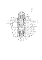
- FIG. 1 is a front (axial direction) cross-sectional view of a lash adjuster 20 according to the first embodiment of the present invention
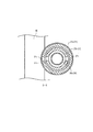
- FIG. 2 is a plan cross-sectional view of the lash adjuster 20 of FIG.
- the lash adjuster includes a bottomed cylindrical body 21, a bottomed cylindrical plunger 22, a plunger cap 27 in contact with the upper surface of the plunger 22, and a cylindrical sleeve 30 tightly fitted in the plunger cap 27. It consists of.
- the lash adjuster 20 inserts and fixes the body 21 into a fixing hole provided in the cylinder head 10 of the internal combustion engine.
- the body 21 includes a cylindrical portion 21a and a bottom portion 21b, and a plunger 22 and a plunger cap 27 are slidably inserted into the cylindrical portion 21a from below.
- a body side hole 21 c for introducing oil from the oil gallery 40 is provided in the cylindrical portion 21 a of the body 21.
- the body side hole 21c is perpendicular to the axis of the body 21 and passes through the cylinder portion 21a.
- the body side hole 21c is formed on the inner peripheral surface side of the cylinder portion 21a from the diameter of the body side hole 21c in the circumferential direction. A large groove is processed so that oil can flow in and out smoothly.
- the plunger 22 inserted into the lower portion of the body 21 is composed of a cylindrical portion 22a and a bottom portion 22b integrated therewith.
- the check valve mechanism provided on the bottom portion 22b allows the inside of the lash adjuster 20 to be stored in the reserve chamber. 41 and a high-pressure chamber 42.
- the check valve mechanism includes an upper and lower communication hole 22c provided substantially at the center of the bottom 22b of the plunger 22, a check ball 24 that is in contact with the upper and lower communication hole 22c below the upper and lower communication hole 22c, and holds the check ball 24.
- a spring 25 that is disposed in the ball cage 26 and biases the check ball 24 upward.
- the ball cage 26 is configured to be supported by a plunger spring 23 that urges the plunger 22 upward.
- the plunger cap 27 is slidably inserted into the body 21 like the plunger 22.
- the plunger cap 27 includes a large-diameter portion 27a that is a sliding portion with the body 21 and an upper small-diameter portion 27b.
- the upper portion of the small-diameter portion 27b has a hemispherical shape, and contacts the rocker arm 17 at this hemispherical portion. .
- An oil passage hole in the vertical direction is provided at the upper end of the small diameter portion 27b, and the oil in the lash adjuster 20 overflows to lubricate the valve mechanism.
- the lower surface of the plunger cap 27 is in contact with the upper surface of the plunger 22 and slides up and down in a substantially integrated state with the plunger 22.
- the plunger cap 27 is provided with two cap side holes 27c.
- the cap side hole 27c is provided at a position communicating with the body side hole 21c, guides oil from the oil gallery 40 provided in the cylinder head 10 into the plunger 22, and is easy to move and has a low density including air. Guide the oil to the oil gallery 40.
- the two body side holes 21 c and 21 c are arranged in one plane perpendicular to the axis of the body 21. When two or more cap side holes 27c are provided, they are arranged in the same manner. It should be noted that the arrangement in “in one vertical plane” includes the case where it is the axis of the cap side hole 27c and the case where it is a part of the cap side hole 27c.
- the cap side hole 27c of the plunger cap 27 is perpendicular to the axis of the body 21 and passes through the large diameter portion 27a of the plunger cap 27.
- This cap is provided circumferentially on the outer peripheral surface side of the large diameter portion 27a.
- a groove having a width larger than the diameter of the side hole 27c is processed so that oil can be smoothly flowed in from the body side hole 21c and oil can be flowed out from the cap side hole 27c.
- the outer diameter of the large-diameter portion 27a of the plunger cap 27 that slides with the body 21 is different between the upper and lower sides of the cap side hole 27c.
- the portion located on the upper side of the groove including the cap side hole 27c has a smaller diameter than the portion located on the lower side thereof, and the oil passage resistance between the body 21 and the large diameter portion 27a. Is configured to be small.
- a cap retainer 31 is provided at the upper open end of the body 21 to hold the plunger cap 27 so that the plunger 22 and the plunger cap 27 do not fall off the body 21 when the lash adjuster 20 is assembled.
- a cylindrical sleeve 30 is tightly fitted to the inner periphery of the large diameter portion 27a of the plunger cap 27.
- the sleeve 30 is configured by opening both ends of a cylinder and arranging three types of cylindrical portions with different diameters in the axial direction.
- the plunger cap 27 is tightly fitted to the large-diameter portion 30a having the largest diameter.
- the first small-diameter portion 30c having a smaller diameter than the large-diameter portion 30a and further to the upper portion of the large-diameter portion 30a.
- the sleeve 30 is integrally formed by providing a second small diameter portion 30d having a smaller diameter than the first small diameter portion 30c and providing a tapered portion 30b therebetween.
- the gap between the inside of the small diameter portion 27 b of the plunger cap 27 and the first small diameter portion 30 c of the sleeve 30 is configured to be small.
- the oil passage resistance between the small-diameter portion 27b and the first small-diameter portion 30c increases, and the oil often passes through the body side hole 21c and the cap side hole 27c.
- Low-density oil containing air is less likely to be stored in the reserve chamber 41.
- the edge processing of the cap side holes 21c can be performed in one step. Side management can be facilitated and processing costs can be reduced.
- cap side holes 27c are an even number, two holes can be processed at a time from the side of the plunger cap 27. This can further reduce the processing cost.
- the oil passage resistance of the outer periphery of the large-diameter portion 27a of the plunger cap 27 which is inserted into the body 21 and slides in the axial direction is positioned downward from the cap side hole 27c.
- FIG. 3 is a front view of the plunger cap 27 constituting the lash adjuster 20 according to the second embodiment of the present invention
- FIG. 4 is a front view of the plunger cap 27 constituting the lash adjuster 20 according to the third embodiment. Show.
- an oil passage parallel adjusting groove 28 is provided in a portion of the outer periphery of the large-diameter portion 27a of the plunger cap 27 located on the cap side hole 27c.
- 3A shows the parallel adjustment groove 28a that communicates with the top and bottom
- FIG. 3B shows the case where the parallel adjustment groove 28b is provided but does not communicate with the top and bottom.
- the passage resistance is adjusted by the groove width and groove depth. And the passage resistance can be easily changed.
- a non-parallel adjustment groove 29 for oil passage is provided on the outer periphery of the large-diameter portion 27a of the plunger cap 27 on the cap side hole 27c.
- the non-parallel adjustment groove 29 is configured to be inclined 45 degrees or more (75 degrees in the present embodiment) from the axis of the plunger cap 27 so that the length of the groove can be increased.
- the passage resistance can be adjusted by the length of the groove, and the passage resistance can be easily changed.
Landscapes
- Engineering & Computer Science (AREA)
- Mechanical Engineering (AREA)
- General Engineering & Computer Science (AREA)
- Valve-Gear Or Valve Arrangements (AREA)
Abstract
Priority Applications (6)
| Application Number | Priority Date | Filing Date | Title |
|---|---|---|---|
| CA2935313A CA2935313C (fr) | 2014-01-20 | 2015-01-06 | Rattrapeur de jeu hydraulique |
| KR1020167020465A KR101672266B1 (ko) | 2014-01-20 | 2015-01-06 | 유압식 래시 어저스터 |
| CN201580005103.XA CN106414919B (zh) | 2014-01-20 | 2015-01-06 | 油压式间隙调节器 |
| US15/111,072 US9803518B2 (en) | 2014-01-20 | 2015-01-06 | Hydraulic lash adjuster |
| EP15736942.2A EP3098402B1 (fr) | 2014-01-20 | 2015-01-06 | Rattrapeur de jeu hydraulique |
| JP2015557790A JP5948511B2 (ja) | 2014-01-20 | 2015-01-06 | 油圧式ラッシュアジャスタ |
Applications Claiming Priority (2)
| Application Number | Priority Date | Filing Date | Title |
|---|---|---|---|
| JP2014007795 | 2014-01-20 | ||
| JP2014-007795 | 2014-01-20 |
Publications (1)
| Publication Number | Publication Date |
|---|---|
| WO2015107937A1 true WO2015107937A1 (fr) | 2015-07-23 |
Family
ID=53542827
Family Applications (1)
| Application Number | Title | Priority Date | Filing Date |
|---|---|---|---|
| PCT/JP2015/050144 Ceased WO2015107937A1 (fr) | 2014-01-20 | 2015-01-06 | Rattrapeur de jeu hydraulique |
Country Status (7)
| Country | Link |
|---|---|
| US (1) | US9803518B2 (fr) |
| EP (1) | EP3098402B1 (fr) |
| JP (1) | JP5948511B2 (fr) |
| KR (1) | KR101672266B1 (fr) |
| CN (1) | CN106414919B (fr) |
| CA (1) | CA2935313C (fr) |
| WO (1) | WO2015107937A1 (fr) |
Cited By (2)
| Publication number | Priority date | Publication date | Assignee | Title |
|---|---|---|---|---|
| WO2018150847A1 (fr) * | 2017-02-17 | 2018-08-23 | 株式会社オティックス | Poussoir |
| JP2024083666A (ja) * | 2022-12-12 | 2024-06-24 | 株式会社オティックス | ラッシュアジャスタ |
Families Citing this family (2)
| Publication number | Priority date | Publication date | Assignee | Title |
|---|---|---|---|---|
| CN108266242B (zh) * | 2016-12-30 | 2022-02-22 | 舍弗勒技术股份两合公司 | 用于气门机构的气门间隙自动补偿器 |
| JP7099260B2 (ja) * | 2018-11-06 | 2022-07-12 | トヨタ自動車株式会社 | 内燃機関の動弁システム |
Citations (8)
| Publication number | Priority date | Publication date | Assignee | Title |
|---|---|---|---|---|
| JPS63170509A (ja) | 1987-10-23 | 1988-07-14 | Nippon Seiko Kk | 油圧式ラッシュアジャスタ |
| JPH01114903U (fr) * | 1988-01-27 | 1989-08-02 | ||
| JPH0335208U (fr) * | 1989-08-09 | 1991-04-05 | ||
| JPH04125605U (ja) * | 1991-05-01 | 1992-11-16 | 三菱自動車工業株式会社 | 内燃機関用気体排除部材付きラツシユアジヤスタ |
| DE19805511A1 (de) * | 1998-02-11 | 1999-08-12 | Bayerische Motoren Werke Ag | Hydraulisches Ventilspiel-Ausgleichselement für einen Ventiltrieb einer Brennkraftmaschine |
| US6959677B2 (en) | 2004-02-12 | 2005-11-01 | Ina-Schaeffler Kg | Hydraulic support element |
| JP2008232125A (ja) * | 2007-03-23 | 2008-10-02 | Otics Corp | ラッシュアジャスタ装置 |
| JP2010261357A (ja) * | 2009-05-07 | 2010-11-18 | Otics Corp | ピボット部材及びロッカアームへの潤滑油供給構造 |
Family Cites Families (2)
| Publication number | Priority date | Publication date | Assignee | Title |
|---|---|---|---|---|
| US7845327B2 (en) * | 2007-08-19 | 2010-12-07 | Ford Global Technologies, Llc | Hydraulic lash adjuster with damping device |
| DE102008025036A1 (de) * | 2008-05-24 | 2009-11-26 | Schaeffler Kg | Hydraulisches Abstützelement |
-
2015
- 2015-01-06 US US15/111,072 patent/US9803518B2/en not_active Expired - Fee Related
- 2015-01-06 WO PCT/JP2015/050144 patent/WO2015107937A1/fr not_active Ceased
- 2015-01-06 CA CA2935313A patent/CA2935313C/fr active Active
- 2015-01-06 EP EP15736942.2A patent/EP3098402B1/fr active Active
- 2015-01-06 CN CN201580005103.XA patent/CN106414919B/zh not_active Expired - Fee Related
- 2015-01-06 KR KR1020167020465A patent/KR101672266B1/ko not_active Expired - Fee Related
- 2015-01-06 JP JP2015557790A patent/JP5948511B2/ja not_active Expired - Fee Related
Patent Citations (8)
| Publication number | Priority date | Publication date | Assignee | Title |
|---|---|---|---|---|
| JPS63170509A (ja) | 1987-10-23 | 1988-07-14 | Nippon Seiko Kk | 油圧式ラッシュアジャスタ |
| JPH01114903U (fr) * | 1988-01-27 | 1989-08-02 | ||
| JPH0335208U (fr) * | 1989-08-09 | 1991-04-05 | ||
| JPH04125605U (ja) * | 1991-05-01 | 1992-11-16 | 三菱自動車工業株式会社 | 内燃機関用気体排除部材付きラツシユアジヤスタ |
| DE19805511A1 (de) * | 1998-02-11 | 1999-08-12 | Bayerische Motoren Werke Ag | Hydraulisches Ventilspiel-Ausgleichselement für einen Ventiltrieb einer Brennkraftmaschine |
| US6959677B2 (en) | 2004-02-12 | 2005-11-01 | Ina-Schaeffler Kg | Hydraulic support element |
| JP2008232125A (ja) * | 2007-03-23 | 2008-10-02 | Otics Corp | ラッシュアジャスタ装置 |
| JP2010261357A (ja) * | 2009-05-07 | 2010-11-18 | Otics Corp | ピボット部材及びロッカアームへの潤滑油供給構造 |
Cited By (5)
| Publication number | Priority date | Publication date | Assignee | Title |
|---|---|---|---|---|
| WO2018150847A1 (fr) * | 2017-02-17 | 2018-08-23 | 株式会社オティックス | Poussoir |
| JPWO2018150847A1 (ja) * | 2017-02-17 | 2019-08-08 | 株式会社オティックス | タペット |
| US10794236B2 (en) | 2017-02-17 | 2020-10-06 | Otics Corporation | Tappet |
| JP2024083666A (ja) * | 2022-12-12 | 2024-06-24 | 株式会社オティックス | ラッシュアジャスタ |
| JP7850439B2 (ja) | 2022-12-12 | 2026-04-23 | 株式会社オティックス | ラッシュアジャスタ |
Also Published As
| Publication number | Publication date |
|---|---|
| CA2935313A1 (fr) | 2015-07-23 |
| EP3098402B1 (fr) | 2020-03-04 |
| EP3098402A4 (fr) | 2017-08-23 |
| CN106414919A (zh) | 2017-02-15 |
| CN106414919B (zh) | 2018-01-19 |
| EP3098402A1 (fr) | 2016-11-30 |
| KR20160097370A (ko) | 2016-08-17 |
| US20160376936A1 (en) | 2016-12-29 |
| JPWO2015107937A1 (ja) | 2017-03-23 |
| KR101672266B1 (ko) | 2016-11-03 |
| JP5948511B2 (ja) | 2016-07-06 |
| CA2935313C (fr) | 2017-01-24 |
| US9803518B2 (en) | 2017-10-31 |
Similar Documents
| Publication | Publication Date | Title |
|---|---|---|
| EP2441928B1 (fr) | Dispositif de réglage de jeu hydraulique pour moteur à combustion interne | |
| JP5948511B2 (ja) | 油圧式ラッシュアジャスタ | |
| JP5961444B2 (ja) | ロッカアームの潤滑構造 | |
| EP2767683B1 (fr) | Régulateur hydraulique de jeu | |
| US9080469B2 (en) | Lash adjuster | |
| US9206711B2 (en) | Lash adjuster | |
| CN101939511A (zh) | 间隙调节器 | |
| JP6296048B2 (ja) | 内燃機関の動弁装置 | |
| US10202876B2 (en) | Lash adjuster | |
| JP2014009644A (ja) | ラッシュアジャスタ | |
| JP6091802B2 (ja) | ラッシュアジャスタ | |
| JP6691409B2 (ja) | ピボット装置 | |
| JP6217337B2 (ja) | エンジンのバルブ構造 | |
| US7556006B2 (en) | Valve mechanism of engine | |
| JP5538275B2 (ja) | 頭上弁エンジンの動弁装置 | |
| JP6246066B2 (ja) | ラッシュアジャスタ | |
| JP6053395B2 (ja) | ラッシュアジャスタ | |
| JP6279955B2 (ja) | ラッシュアジャスタ | |
| JP2013227944A (ja) | ラッシュアジャスタ | |
| JP2006283562A (ja) | 内燃機関用バルブ回転装置 |
Legal Events
| Date | Code | Title | Description |
|---|---|---|---|
| 121 | Ep: the epo has been informed by wipo that ep was designated in this application |
Ref document number: 15736942 Country of ref document: EP Kind code of ref document: A1 |
|
| DPE1 | Request for preliminary examination filed after expiration of 19th month from priority date (pct application filed from 20040101) | ||
| ENP | Entry into the national phase |
Ref document number: 2015557790 Country of ref document: JP Kind code of ref document: A |
|
| ENP | Entry into the national phase |
Ref document number: 2935313 Country of ref document: CA |
|
| WWE | Wipo information: entry into national phase |
Ref document number: 15111072 Country of ref document: US |
|
| REEP | Request for entry into the european phase |
Ref document number: 2015736942 Country of ref document: EP |
|
| WWE | Wipo information: entry into national phase |
Ref document number: 2015736942 Country of ref document: EP |
|
| NENP | Non-entry into the national phase |
Ref country code: DE |
|
| ENP | Entry into the national phase |
Ref document number: 20167020465 Country of ref document: KR Kind code of ref document: A |