WO2015145909A1 - Pneu - Google Patents
Pneu Download PDFInfo
- Publication number
- WO2015145909A1 WO2015145909A1 PCT/JP2014/084411 JP2014084411W WO2015145909A1 WO 2015145909 A1 WO2015145909 A1 WO 2015145909A1 JP 2014084411 W JP2014084411 W JP 2014084411W WO 2015145909 A1 WO2015145909 A1 WO 2015145909A1
- Authority
- WO
- WIPO (PCT)
- Prior art keywords
- tire
- profile line
- width direction
- land portion
- center
- Prior art date
- Legal status (The legal status is an assumption and is not a legal conclusion. Google has not performed a legal analysis and makes no representation as to the accuracy of the status listed.)
- Ceased
Links
Images


Classifications
-
- B—PERFORMING OPERATIONS; TRANSPORTING
- B60—VEHICLES IN GENERAL
- B60C—VEHICLE TYRES; TYRE INFLATION; TYRE CHANGING; CONNECTING VALVES TO INFLATABLE ELASTIC BODIES IN GENERAL; DEVICES OR ARRANGEMENTS RELATED TO TYRES
- B60C11/00—Tyre tread bands; Tread patterns; Anti-skid inserts
- B60C11/03—Tread patterns
- B60C11/0327—Tread patterns characterised by special properties of the tread pattern
- B60C11/0332—Tread patterns characterised by special properties of the tread pattern by the footprint-ground contacting area of the tyre tread
-
- B—PERFORMING OPERATIONS; TRANSPORTING
- B60—VEHICLES IN GENERAL
- B60C—VEHICLE TYRES; TYRE INFLATION; TYRE CHANGING; CONNECTING VALVES TO INFLATABLE ELASTIC BODIES IN GENERAL; DEVICES OR ARRANGEMENTS RELATED TO TYRES
- B60C11/00—Tyre tread bands; Tread patterns; Anti-skid inserts
- B60C11/0083—Tyre tread bands; Tread patterns; Anti-skid inserts characterised by the curvature of the tyre tread
-
- B—PERFORMING OPERATIONS; TRANSPORTING
- B60—VEHICLES IN GENERAL
- B60C—VEHICLE TYRES; TYRE INFLATION; TYRE CHANGING; CONNECTING VALVES TO INFLATABLE ELASTIC BODIES IN GENERAL; DEVICES OR ARRANGEMENTS RELATED TO TYRES
- B60C11/00—Tyre tread bands; Tread patterns; Anti-skid inserts
- B60C11/03—Tread patterns
- B60C11/0302—Tread patterns directional pattern, i.e. with main rolling direction
-
- B—PERFORMING OPERATIONS; TRANSPORTING
- B60—VEHICLES IN GENERAL
- B60C—VEHICLE TYRES; TYRE INFLATION; TYRE CHANGING; CONNECTING VALVES TO INFLATABLE ELASTIC BODIES IN GENERAL; DEVICES OR ARRANGEMENTS RELATED TO TYRES
- B60C11/00—Tyre tread bands; Tread patterns; Anti-skid inserts
- B60C11/03—Tread patterns
- B60C11/13—Tread patterns characterised by the groove cross-section, e.g. for buttressing or preventing stone-trapping
- B60C11/1376—Three dimensional block surfaces departing from the enveloping tread contour
-
- B—PERFORMING OPERATIONS; TRANSPORTING
- B60—VEHICLES IN GENERAL
- B60C—VEHICLE TYRES; TYRE INFLATION; TYRE CHANGING; CONNECTING VALVES TO INFLATABLE ELASTIC BODIES IN GENERAL; DEVICES OR ARRANGEMENTS RELATED TO TYRES
- B60C11/00—Tyre tread bands; Tread patterns; Anti-skid inserts
- B60C11/03—Tread patterns
- B60C2011/0337—Tread patterns characterised by particular design features of the pattern
- B60C2011/0339—Grooves
- B60C2011/0341—Circumferential grooves
-
- B—PERFORMING OPERATIONS; TRANSPORTING
- B60—VEHICLES IN GENERAL
- B60Y—INDEXING SCHEME RELATING TO ASPECTS CROSS-CUTTING VEHICLE TECHNOLOGY
- B60Y2200/00—Type of vehicle
Definitions
- the present invention relates to a pneumatic tire in which steering stability performance and uneven wear resistance performance are improved in a well-balanced manner.
- the grounding property is improved by making the land portion into a curved shape that protrudes outward in the tire radial direction.
- the curve shape determination method disclosed in Patent Document 1 is a method of using one type of tread profile line in the entire tire width direction of the tread surface.
- the present invention has been made in view of the above circumstances, and an object of the present invention is to provide a pneumatic tire in which steering stability performance and uneven wear resistance performance are improved in a well-balanced manner.
- the pneumatic tire according to the present invention includes a center main groove extending in the tire circumferential direction on each side in the tire width direction across the tire equator plane, and extending in the tire circumferential direction outside the center main groove in the tire width direction.
- One shoulder main groove is provided, and five types of land portions extending in the tire circumferential direction are defined by the four main grooves.
- a curve including all the two end points in the tire width direction of the two center main grooves in the tire meridian cross-sectional view is taken as a reference profile line. In this case, the profile line of the center land portion defined by the two center main grooves protrudes outward in the tire radial direction from the reference profile line.
- Two profile lines that exist on each side in the tire width direction across the tire equatorial plane and include the outermost point in the tire width direction of the center main groove and both end points in the tire width direction of the shoulder main groove The profile lines of the sub-center land portion and the shoulder land portion that are sequentially formed on the outer side in the tire width direction from the center main groove protrude outward in the tire radial direction from the reference profile line.
- the profile line of the land portion formed in the tread portion is improved.
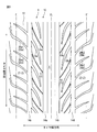
- FIG. 1 is a plan view showing a tread surface of a pneumatic tire according to an embodiment of the present invention.
- FIG. 2 is a tire meridional section showing a tread portion of the pneumatic tire shown in FIG. 1.
- FIG. 3 is a plan view showing the shape of the ground contact surface of the pneumatic tire, (a) shows a conventional pneumatic tire, and (b) shows the pneumatic tire of the present embodiment.
- FIG. 4 is an enlarged view of a circled portion B in FIG.
- FIG. 5 is a tire meridian cross-sectional view showing a modification of the example shown in FIG.
- the tire radial direction means a direction orthogonal to the rotational axis of the pneumatic tire
- the tire radial inner side is the side toward the rotational axis in the tire radial direction
- the tire radial outer side is in the tire radial direction.
- the tire circumferential direction refers to a circumferential direction with the rotation axis as a central axis.
- the tire width direction means a direction parallel to the rotation axis
- the inner side in the tire width direction is the side toward the tire equator plane (tire equator line) in the tire width direction
- the outer side in the tire width direction is in the tire width direction.
- the tire equator plane is a plane that is orthogonal to the rotational axis of the pneumatic tire and passes through the center of the tire width of the pneumatic tire.
- FIG. 1 is a plan view showing a tread surface of a pneumatic tire according to an embodiment of the present invention.
- symbol CL of FIG. 1 shows a tire equator surface
- symbols E and E 'each show the grounding end line of a pneumatic tire.
- the tread pattern shown in FIG. 1 is a symmetrical pattern between both sides of the tire equatorial plane CL in the tire width direction.
- the tread portion 10 of the pneumatic tire 1 is made of a rubber material (tread rubber), exposed at the outermost side in the tire radial direction of the pneumatic tire 1, and the surface thereof is the contour of the pneumatic tire 1.
- the surface of the tread portion 10 is formed as a tread surface 12 that becomes a surface that comes into contact with the road surface when a vehicle (not shown) on which the pneumatic tire 1 is mounted travels.
- the tread surface 12 is provided with four circumferential grooves 14a, 14b, 14c, 14d extending in the tire circumferential direction at predetermined intervals in the tire width direction.
- the circumferential grooves 14a and 14c are provided on one side in the tire width direction
- the circumferential grooves 14b and 14d are provided on the other side in the tire width direction.
- the circumferential grooves 14a and 14b may be referred to as a center main groove
- the circumferential grooves 14c and 14d may be referred to as a shoulder main groove.
- the circumferential grooves 14a to 14d are not limited to grooves extending linearly in the tire circumferential direction as shown in FIG. 1, but have an amplitude in the tire width direction, and are wavy or zigzag-shaped. And a groove extending in the tire circumferential direction.
- the tread surface 12 has a first inclined groove that communicates the center main groove 14a (14b) with the tire equatorial plane CL and the shoulder main groove 14c (14d) far from the tire equatorial plane CL.
- 16a (16b) is provided at a constant pitch in the tire circumferential direction.
- the tread surface 12 has a second inclined groove 18a (18b) extending inward in the tire width direction from the shoulder main groove 14c (14d) and terminating in the land portion in the tire circumferential direction.
- a second inclined groove 18a (18b) extending inward in the tire width direction from the shoulder main groove 14c (14d) and terminating in the land portion in the tire circumferential direction.
- a third inclined groove extending from the shoulder main groove 14c (14d) to the outer side in the tire width direction beyond the grounding end line E (E ').
- 20a (20b) are provided at a constant pitch in the tire circumferential direction.
- the third inclined groove 20a (20b) includes, in particular, two types of grooves 20a1 and 20a2 (20b1 and 20b2) having different shapes on the outer side in the tire width direction than the grounding dotted line E (E ′). Grooves are provided alternately in the tire circumferential direction.
- the plurality of grooves 14a, 14b, 14c, 14d, 16a, 16b, 18a, 18b, 20a, and 20b are used to provide five types of land portions (center land portion X, sub-center land portion Y1). Y2 and shoulder land portions Z1, Z2) are defined.
- the center land portion X is a so-called rib, and the sub-center land portions Y1 and Y2 and the shoulder land portions Z1 and Z2 are blocks.
- FIG. 2 is a tire meridional sectional view showing a tread portion of the pneumatic tire shown in FIG.
- the same reference numerals in FIG. 2 as those in FIG. 1 denote the same members as those in FIG.
- both end points in the tire width direction of the center main grooves 14a and 14b are A1, A2, A3, and A4, respectively, and both end points in the tire width direction of the shoulder main grooves 14c and 14d are A5 and A6, respectively. , A7 and A8.
- the reference profile line PL0 may be an arc, an elliptical arc, or any other curve.
- the profile line PL1 of the center land portion X defined by the two center main grooves 14a and 14b is more than the reference profile line PL0. It protrudes outward in the tire radial direction.
- a curve including tire width direction end points A5 and A6 (A7, A8) is defined as a profile line PL2 (PL3).
- This profile line PL2 (PL3) is a common profile for the sub-center land portion Y1 (Y2) and the shoulder land portion Z1 (Z2) that are partitioned in order in the tire width direction outer side than the center main groove 14a (14b). Line.
- the profile line PL2 protrudes outward in the tire radial direction from the reference profile line PL0.
- the profile line PL1 and the profile lines PL2 and PL3 are projected outward in the tire radial direction from the reference profile line PL0, and the following operational effects are obtained.
- FIG. 3 is a plan view showing a contact surface shape of the pneumatic tire.
- the figure (a) shows the conventional pneumatic tire
- (b) shows the pneumatic tire of this Embodiment shown in FIG.1 and FIG.2.
- the example shown to (a) shows the tread pattern shown in FIG. 1, all of profile line PL1, PL2, PL3 shown in FIG. 2 corresponds to the reference profile line PL0.
- the profile lines PL1, PL2, and PL3 shown in FIG. 2 all coincide with the reference profile line PL0.
- FIG. 3A due to the low contact pressure at the center position in the tire width direction of the land portion, both ends in the tire circumferential direction near the center position are directed toward the inside of the land portion.
- the outer peripheral line of the contact surface becomes uneven (see particularly the dotted line in FIG. 3A). Due to the uneven shape of the outer peripheral line, a portion where the ground contact length is shortened near the center position in the tire width direction of each land portion may occur, which may deteriorate the ground contact property and, consequently, the steering stability performance.
- profile lines PL1, PL2, and PL3 shown in FIG. 2 are all projected in the tire radial direction with respect to the reference profile line PL0.
- the contact pressure near the center position in the tire width direction of the land portion can be made substantially equal to the contact pressure at both outer positions in the tire width direction.
- it can suppress that the tire circumferential direction both ends near the said center position deform
- each land portion X, Y1, Y2, Z1, Z2 has one tire circumferential end boundary (both on the stepping side and the kicking side). It will be located on a smooth curve. Therefore, the contact length in the tire width direction in each of the land portions X, Y1, Y2, Z1, and Z2 can be made substantially uniform, and as a result, the contact property can be improved (Operation 1).
- one profile line PL2 (L3) is set across the sub-center land portion Y1 (Y2) and the shoulder land portion Z1 (Z2). That is, it is significant that the outer contour of the sub-center land portion Y1 (Y2) and the outer contour of the shoulder land portion Z1 (Z2) are located on the same curve.
- the ground contact property in the tire width direction can be improved (Operation 1), and the ground property between the land portions in the shoulder region can be improved.
- the amount of change in the tire width direction can be smoothed (Operation 2). Therefore, according to the pneumatic tire of the present embodiment, the above actions 1 and 2 combine to provide not only excellent steering stability performance (including both straight running performance and turning performance) but also excellent uneven wear resistance performance. Can be realized.
- the pneumatic tire which concerns on this Embodiment shown above has the same meridional cross-sectional shape as the conventional pneumatic tire.
- the meridional cross-sectional shape of the pneumatic tire refers to a cross-sectional shape of the pneumatic tire that appears on a plane perpendicular to the tire equatorial plane.
- the pneumatic tire according to the present embodiment has a bead portion, a sidewall portion, a shoulder portion, and a tread portion from the inner side in the tire radial direction toward the outer side in a tire meridian cross-sectional view.
- the pneumatic tire includes, for example, a carcass layer extending from a tread portion to bead portions on both sides and wound around a pair of bead cores in a tire meridional section, and a tire radial outside of the carcass layer.
- the belt layer and the belt reinforcing layer are sequentially formed.
- the pneumatic tire of the present embodiment is subjected to normal manufacturing processes, that is, a tire material mixing process, a tire material processing process, a green tire molding process, a vulcanization process, and an inspection process after vulcanization. It is obtained through the process.
- a tire material mixing process for example, the groove formed in the tread portion shown in FIGS. 1 and 2 and the convex portion corresponding to the land portion. And a recessed part is formed and vulcanization
- the shape of the reference profile line PL0 is determined.
- the curvature radius is determined.
- the radius of curvature it is important to set various values depending on the tire size. In the present embodiment, the radius of curvature is set to be 5 to 20 times the tire cross-sectional height.
- an arc PL0 having a radius of curvature R0 including points A1 and A3 inside the tire width direction of the two center main grooves 14a and 14b and having a center position on the tire equatorial plane CL is determined.
- a curvature radius R1 (0.3 ⁇ R1 / R0 ⁇ 0%) Including the points A1 and A3 on the inner side in the tire width direction of the two center main grooves 14a and 14b and smaller than the curvature radius R0 of the arc PL0. Determine the arc PL1 having 4).
- a circular arc PL2 (PL3) having (R3) /R0 ⁇ 0.95) is determined.
- the arc PL2 (PL3) extends from the point A2 (A4) to the outside in the tire width direction beyond the contact end line E (E ′), and intersects the arc PL0 at the point P (P ′).
- the arc PL1 and the arc PL2 (PL3) intersect on the circumferential groove 14a (14b) close to the tire equator plane CL. Further, the points P (P ′) are respectively positioned on the outer side in the tire width direction from the contact end line E (E ′) by a dimension of 3% to 5% of the tire contact width.
- the reference profile line PL0 itself can be made sufficiently convex in the tire radial direction by setting the radius of curvature to 20 times or less of the tire cross-section height.
- the curvature radii of the profile lines PL1, PL2, and PL3 protruding outward in the tire radial direction from the reference profile line PL0 can be made sufficiently small to sufficiently improve the ground contact property of each land portion.
- the tire main-direction end points A1 to A4 of the center main grooves 14a and 14b are formed on the reference profile line PL0 shown in FIG. Determine.
- the profile line PL1 of the center land portion X shown in FIG. 2 is defined, and these profile lines PL2 (PL3) extending across the sub-center land portion Y1 (Y2) and the shoulder land portion Z1 (Z2) are defined. Determine.
- the maximum protrusion amount of the profile line PL1 of the center land portion X shown in FIG. 2 to the outer side in the tire radial direction with respect to the reference profile line PL0 is 0.2 mm or more and 0.5 mm or less (additional configuration) 1) is preferred.
- FIG. 4 is an enlarged view of a circled portion B in FIG.
- the maximum protrusion amount S1 of the profile line PL1 of the center land portion X to the outer side in the tire radial direction with respect to the reference profile line PL0 is from the reference profile line PL0 to the profile line PL1.
- the maximum dimension in the tire radial direction shall be said.
- the contact pressure in the vicinity of the center position in the tire width direction of the center land portion X can be made closer to the contact pressure in both outer positions in the tire width direction. .
- the grip force with the road surface can be increased, and in particular, the steering performance when the vehicle is traveling straight can be improved, so that the straight traveling performance (steering stability performance) can be further enhanced.
- the protrusion amount in the tire radial direction in the vicinity of the center position in the tire width direction can be suppressed for the center land portion X.
- the uneven wear resistance can be further improved without excessively increasing the wear amount in the vicinity of the center position with respect to the wear amount at other positions.
- the said effect can be show
- FIG. 5 is a tire meridian cross-sectional view showing a modification of the example shown in FIG. That is, the example shown in FIG. 5 is an example of a tread pattern that is similar to the tread pattern shown in FIG. 1, but has an asymmetric pattern between both sides of the tire equatorial plane CL in the tire width direction. In other words, the example shown in FIG. 5 is an example in which the vehicle mounting direction is designated. In FIG.
- reference numeral 10 ′ denotes a tread portion
- reference numeral 12 ′ denotes a tread surface
- reference numerals 14 a ′, 14 b ′, 14 c ′, and 14 d ′ denote circumferential grooves
- Z1 ′, Z2 ′ indicate land portions.
- reference symbol PL0 ′ indicates a reference profile line
- reference symbols PL1 ′, PL2 ′, and Pl3 ′ indicate profile lines.
- reference numeral S2 denotes the maximum dimension in the tire radial direction from the reference profile line PL0 ′ to the profile line PL2 ′ (PL3 ′).
- the profile lines PL2 ′ (the sub-center land portion Y1 ′ (Y2 ′) and the shoulder land portion Z1 ′ (Z2 ′) PL3 ′) has a maximum protrusion amount S2 (S3) to the outer side in the tire radial direction with respect to the reference profile line PL0 ′ of 0.6 mm to 2.0 mm, and the maximum protrusion amount S2 (S3) is mounted on the vehicle.
- the inner profile line PL2 ′ is preferably larger than the vehicle-mounted outer profile line PL3 ′ (additional form 2).
- the sub-center land portion Y1 ′ (Y2 ′) and the shoulder land portion Z1 ′ (Z2 ′) are grounded in the vicinity of the center position in the tire width direction.
- the pressure can be made closer to the contact pressure at both outer positions in the tire width direction.
- the grip force with the road surface can be increased, and in particular, the steering performance when the vehicle is traveling straight can be improved, so that the straight traveling performance (steering stability performance) can be further enhanced.
- the maximum protrusion amount S2 (S3) is 2.0 mm or less, the sub-center land portion Y1 ′ (Y2 ′) and the shoulder land portion Z1 ′ (Z2 ′) at the center position in the tire width direction.
- the amount of protrusion in the tire radial direction can be suppressed.
- the uneven wear resistance can be further improved without excessively increasing the wear amount in the vicinity of the center position with respect to the wear amount at other positions.
- the said effect can be show
- the maximum protrusion amount S2 (S3) is made larger in the profile line PL2 ′ on the vehicle mounting inner side than on the profile line PL3 ′ on the vehicle mounting outer side. That is, in the present embodiment, the tire radial direction dimensions of the land portions (sub-center land portion Y1 ′ (Y2 ′) and shoulder land portion Z1 ′ (Z2 ′)) on the outer side of the vehicle where the amount of wear is large when turning are determined. It is enlarged for each corresponding land part on the inner side of the installation. Accordingly, the uneven wear resistance performance can be further enhanced without excessively changing the wear amount of the land portion on the outer side and the inner side of the vehicle from the time when the tire is new to the end of its life.
- Example group 1 shown below is an example group for pneumatic tires in which the vehicle mounting direction is not specified.
- the pneumatic tires of Examples 1 to 5 having a tire size of 235 / 40ZR18 (95Y), the tread pattern shown in FIG. 1, and the tread surface profile lines PL1, PL2, and PL3 shown in FIG. 2 were produced.
- the various conditions of the profile lines on the tread surfaces of the pneumatic tires of Examples 1 to 5 are as shown in Table 1 below.
- the tire size is 235 / 40ZR18 (95Y)
- the tread surface profile lines PL1, PL2, and PL3 shown in FIG. 2 are the same as the pneumatic tire of the first embodiment, except that the tire profile size coincides with the reference profile line PL0.
- a pneumatic tire of Conventional Example 1 having a structure was produced.
- test tires of Examples 1 to 5 and Conventional Example 1 manufactured as described above were assembled on a 18 ⁇ 8.5J rim at 230 kPa and mounted on a sedan type vehicle with a displacement of 2000 cc. (Straight running performance), steering stability performance 2 (turning performance) and uneven wear resistance performance were evaluated.
- Steping stability 1 (straight running performance)
- index evaluation was performed using Conventional Example 1 as a reference (100). This evaluation shows that the steering stability performance 1 (straight running performance) is higher as the index is larger.
- pneumatic tires of Examples 1 to 5 belonging to the technical scope of the present invention are applied to pneumatic tires in which the vehicle mounting direction is not specified.
- the steering stability performances 1 and 2 and the uneven wear resistance are superior to those of the pneumatic tire of Conventional Example 1 that do not belong to the technical scope of the present invention.
- Example group 2 is an example group for pneumatic tires in which the vehicle mounting direction is specified.
- Examples 6 to 10 having a tire size of 235 / 40ZR18 (95Y), a tread pattern similar to the tread pattern shown in FIG. 1, and profile lines PL1 ′, PL2 ′, and PL34 ′ on the tread surface shown in FIG. A pneumatic tire was prepared.
- various conditions of the profile lines on the tread surfaces of the pneumatic tires of Examples 6 to 10 are as shown in Table 2 below.
- the tire size is 235 / 40ZR18 (95Y), and the tread surface profile lines PL1 ′, PL2 ′, and PL3 ′ shown in FIG.
- a pneumatic tire of Conventional Example 2 having the same structure as the entering tire was produced.
- Example 6 to 10 and Conventional Example 2 manufactured as described above were assembled on a rim of 18 ⁇ 8.5 J at 230 kPa and mounted on a sedan type vehicle with a displacement of 2000 cc.
- Steering stability performance 1 (Straight running performance), steering stability performance 2 (turning performance) and uneven wear resistance performance were evaluated. These evaluations were performed according to the evaluation method employed in Example Group 1. These evaluation results are also shown in Table 2.
Landscapes
- Engineering & Computer Science (AREA)
- Mechanical Engineering (AREA)
- Tires In General (AREA)
Abstract
Priority Applications (4)
| Application Number | Priority Date | Filing Date | Title |
|---|---|---|---|
| EP14887326.8A EP3124289B1 (fr) | 2014-03-27 | 2014-12-25 | Pneu |
| US15/129,806 US10857836B2 (en) | 2014-03-27 | 2014-12-25 | Pneumatic tire |
| AU2014388517A AU2014388517B2 (en) | 2014-03-27 | 2014-12-25 | Pneumatic tire |
| CN201480077330.9A CN106103135B (zh) | 2014-03-27 | 2014-12-25 | 充气轮胎 |
Applications Claiming Priority (2)
| Application Number | Priority Date | Filing Date | Title |
|---|---|---|---|
| JP2014066692A JP5812140B2 (ja) | 2014-03-27 | 2014-03-27 | 空気入りタイヤ |
| JP2014-066692 | 2014-03-27 |
Publications (1)
| Publication Number | Publication Date |
|---|---|
| WO2015145909A1 true WO2015145909A1 (fr) | 2015-10-01 |
Family
ID=54194475
Family Applications (1)
| Application Number | Title | Priority Date | Filing Date |
|---|---|---|---|
| PCT/JP2014/084411 Ceased WO2015145909A1 (fr) | 2014-03-27 | 2014-12-25 | Pneu |
Country Status (6)
| Country | Link |
|---|---|
| US (1) | US10857836B2 (fr) |
| EP (1) | EP3124289B1 (fr) |
| JP (1) | JP5812140B2 (fr) |
| CN (1) | CN106103135B (fr) |
| AU (1) | AU2014388517B2 (fr) |
| WO (1) | WO2015145909A1 (fr) |
Cited By (4)
| Publication number | Priority date | Publication date | Assignee | Title |
|---|---|---|---|---|
| WO2016148123A1 (fr) * | 2015-03-17 | 2016-09-22 | 横浜ゴム株式会社 | Pneumatique |
| JP2017081423A (ja) * | 2015-10-28 | 2017-05-18 | 株式会社ブリヂストン | 空気入りタイヤ |
| US10647161B2 (en) | 2015-07-31 | 2020-05-12 | The Yokohama Rubber Co., Ltd. | Pneumatic tire |
| DE112016003477B4 (de) | 2015-07-31 | 2022-12-22 | The Yokohama Rubber Co., Ltd. | Luftreifen |
Families Citing this family (7)
| Publication number | Priority date | Publication date | Assignee | Title |
|---|---|---|---|---|
| JP2872287B2 (ja) | 1989-08-16 | 1999-03-17 | セントラル硝子株式会社 | 合わせガラスの接着方法並びにその装置 |
| JP6599218B2 (ja) * | 2015-11-18 | 2019-10-30 | Toyo Tire株式会社 | 空気入りタイヤ |
| JP6897444B2 (ja) * | 2017-09-15 | 2021-06-30 | 住友ゴム工業株式会社 | タイヤ |
| US11148472B2 (en) * | 2018-04-06 | 2021-10-19 | Sumitomo Rubber Industries, Ltd. | Tyre |
| JP7124494B2 (ja) * | 2018-07-03 | 2022-08-24 | 横浜ゴム株式会社 | 空気入りタイヤおよび空気入りタイヤの製造方法 |
| JP7136645B2 (ja) * | 2018-09-21 | 2022-09-13 | Toyo Tire株式会社 | 空気入りタイヤ |
| US12151512B2 (en) | 2019-07-01 | 2024-11-26 | The Yokohama Rubber Co., Ltd. | Pneumatic tire |
Citations (4)
| Publication number | Priority date | Publication date | Assignee | Title |
|---|---|---|---|---|
| JPS6334204A (ja) * | 1986-07-18 | 1988-02-13 | ユニロ−ヤル・エングレベルト・ライフエン・ゲゼルシヤフト・ミト・ベシユレンクテル・ハフツング | 車両用タイヤ |
| JPH07164823A (ja) * | 1993-12-17 | 1995-06-27 | Toyo Tire & Rubber Co Ltd | 重荷重用空気入りタイヤ |
| JP2003118317A (ja) * | 2001-10-15 | 2003-04-23 | Yokohama Rubber Co Ltd:The | 空気入りタイヤ |
| JP2014118123A (ja) * | 2012-12-19 | 2014-06-30 | Sumitomo Rubber Ind Ltd | 空気入りタイヤ |
Family Cites Families (13)
| Publication number | Priority date | Publication date | Assignee | Title |
|---|---|---|---|---|
| JPH04103406A (ja) * | 1990-08-24 | 1992-04-06 | Toyo Tire & Rubber Co Ltd | 重荷重用空気入りラジアルタイヤ |
| US5647925A (en) * | 1993-12-17 | 1997-07-15 | Toyo Tire & Rubber Co., Ltd. | Pneumatic tire for heavy-loaded vehicles, with resistance to river wear |
| JPH07172107A (ja) * | 1993-12-20 | 1995-07-11 | Yokohama Rubber Co Ltd:The | 空気入りラジアルタイヤ |
| JPH09136511A (ja) * | 1995-11-16 | 1997-05-27 | Sumitomo Rubber Ind Ltd | 乗用車用ラジアルタイヤ |
| JP4340344B2 (ja) * | 1998-11-04 | 2009-10-07 | 株式会社ブリヂストン | 空気入りタイヤ |
| JP2002029216A (ja) * | 2000-07-19 | 2002-01-29 | Bridgestone Corp | 空気入りタイヤおよびそれの装着方法 |
| JP4233784B2 (ja) * | 2001-12-06 | 2009-03-04 | 株式会社ブリヂストン | 空気入りタイヤ及びその装着方法 |
| JP4408236B2 (ja) * | 2004-03-22 | 2010-02-03 | 株式会社ブリヂストン | 空気入りタイヤ |
| DE102007059290A1 (de) * | 2007-12-08 | 2009-06-10 | Continental Aktiengesellschaft | Fahrzeugluftreifen |
| US20110079334A1 (en) * | 2009-10-02 | 2011-04-07 | Andreas Bott | Tire tread having improved contact pressure distribution |
| JP5739681B2 (ja) * | 2011-01-28 | 2015-06-24 | 株式会社ブリヂストン | 空気入りタイヤ |
| JP5790876B2 (ja) * | 2013-02-25 | 2015-10-07 | 横浜ゴム株式会社 | 空気入りタイヤ |
| JP6186147B2 (ja) * | 2013-03-22 | 2017-08-23 | 東洋ゴム工業株式会社 | 空気入りタイヤ |
-
2014
- 2014-03-27 JP JP2014066692A patent/JP5812140B2/ja active Active
- 2014-12-25 WO PCT/JP2014/084411 patent/WO2015145909A1/fr not_active Ceased
- 2014-12-25 AU AU2014388517A patent/AU2014388517B2/en active Active
- 2014-12-25 CN CN201480077330.9A patent/CN106103135B/zh active Active
- 2014-12-25 EP EP14887326.8A patent/EP3124289B1/fr active Active
- 2014-12-25 US US15/129,806 patent/US10857836B2/en active Active
Patent Citations (4)
| Publication number | Priority date | Publication date | Assignee | Title |
|---|---|---|---|---|
| JPS6334204A (ja) * | 1986-07-18 | 1988-02-13 | ユニロ−ヤル・エングレベルト・ライフエン・ゲゼルシヤフト・ミト・ベシユレンクテル・ハフツング | 車両用タイヤ |
| JPH07164823A (ja) * | 1993-12-17 | 1995-06-27 | Toyo Tire & Rubber Co Ltd | 重荷重用空気入りタイヤ |
| JP2003118317A (ja) * | 2001-10-15 | 2003-04-23 | Yokohama Rubber Co Ltd:The | 空気入りタイヤ |
| JP2014118123A (ja) * | 2012-12-19 | 2014-06-30 | Sumitomo Rubber Ind Ltd | 空気入りタイヤ |
Cited By (7)
| Publication number | Priority date | Publication date | Assignee | Title |
|---|---|---|---|---|
| WO2016148123A1 (fr) * | 2015-03-17 | 2016-09-22 | 横浜ゴム株式会社 | Pneumatique |
| US10759231B2 (en) | 2015-03-17 | 2020-09-01 | The Yokohama Rubber Co., Ltd. | Pneumatic tire |
| US10647161B2 (en) | 2015-07-31 | 2020-05-12 | The Yokohama Rubber Co., Ltd. | Pneumatic tire |
| DE112016003483B4 (de) | 2015-07-31 | 2022-08-18 | The Yokohama Rubber Co., Ltd. | Luftreifen |
| DE112016003477B4 (de) | 2015-07-31 | 2022-12-22 | The Yokohama Rubber Co., Ltd. | Luftreifen |
| DE112016003477B9 (de) | 2015-07-31 | 2023-03-23 | The Yokohama Rubber Co., Ltd. | Luftreifen |
| JP2017081423A (ja) * | 2015-10-28 | 2017-05-18 | 株式会社ブリヂストン | 空気入りタイヤ |
Also Published As
| Publication number | Publication date |
|---|---|
| AU2014388517B2 (en) | 2017-09-07 |
| EP3124289A1 (fr) | 2017-02-01 |
| EP3124289B1 (fr) | 2019-06-05 |
| JP2015189292A (ja) | 2015-11-02 |
| US10857836B2 (en) | 2020-12-08 |
| AU2014388517A1 (en) | 2016-10-20 |
| EP3124289A4 (fr) | 2017-11-29 |
| US20170174009A1 (en) | 2017-06-22 |
| JP5812140B2 (ja) | 2015-11-11 |
| CN106103135A (zh) | 2016-11-09 |
| CN106103135B (zh) | 2019-04-23 |
Similar Documents
| Publication | Publication Date | Title |
|---|---|---|
| JP5812140B2 (ja) | 空気入りタイヤ | |
| JP5835413B1 (ja) | 空気入りタイヤ | |
| JP6292067B2 (ja) | 空気入りタイヤ | |
| CN104903121B (zh) | 充气轮胎 | |
| JP2015134581A (ja) | 空気入りタイヤ | |
| WO2017022309A1 (fr) | Pneumatique | |
| WO2020009049A1 (fr) | Bandage pneumatique | |
| JP2008307950A (ja) | 空気入りタイヤ | |
| WO2020009077A1 (fr) | Pneumatique | |
| JP6658789B2 (ja) | 空気入りタイヤ | |
| JP6348008B2 (ja) | 空気入りタイヤ | |
| JP2015120428A (ja) | 空気入りタイヤ | |
| JP6260247B2 (ja) | 空気入りタイヤ | |
| JP7381833B2 (ja) | 空気入りタイヤ | |
| WO2020045223A1 (fr) | Pneumatique | |
| JP2016107914A (ja) | 空気入りタイヤ | |
| JP2015033985A (ja) | 空気入りタイヤ | |
| JP2019073248A (ja) | 空気入りタイヤ | |
| JP2016055814A (ja) | 空気入りタイヤ | |
| WO2023153022A1 (fr) | Pneumatique |
Legal Events
| Date | Code | Title | Description |
|---|---|---|---|
| 121 | Ep: the epo has been informed by wipo that ep was designated in this application |
Ref document number: 14887326 Country of ref document: EP Kind code of ref document: A1 |
|
| NENP | Non-entry into the national phase |
Ref country code: DE |
|
| WWE | Wipo information: entry into national phase |
Ref document number: 15129806 Country of ref document: US |
|
| ENP | Entry into the national phase |
Ref document number: 2014388517 Country of ref document: AU Date of ref document: 20141225 Kind code of ref document: A |
|
| REEP | Request for entry into the european phase |
Ref document number: 2014887326 Country of ref document: EP |
|
| WWE | Wipo information: entry into national phase |
Ref document number: 2014887326 Country of ref document: EP |