WO2015147064A1 - Composant à noyau magnétique, élément magnétique, et procédé de fabrication de composant à noyau magnétique - Google Patents
Composant à noyau magnétique, élément magnétique, et procédé de fabrication de composant à noyau magnétique Download PDFInfo
- Publication number
- WO2015147064A1 WO2015147064A1 PCT/JP2015/059145 JP2015059145W WO2015147064A1 WO 2015147064 A1 WO2015147064 A1 WO 2015147064A1 JP 2015059145 W JP2015059145 W JP 2015059145W WO 2015147064 A1 WO2015147064 A1 WO 2015147064A1
- Authority
- WO
- WIPO (PCT)
- Prior art keywords
- magnetic
- powder
- amorphous metal
- magnetic core
- core component
- Prior art date
- Legal status (The legal status is an assumption and is not a legal conclusion. Google has not performed a legal analysis and makes no representation as to the accuracy of the status listed.)
- Ceased
Links
Images

Classifications
-
- C—CHEMISTRY; METALLURGY
- C22—METALLURGY; FERROUS OR NON-FERROUS ALLOYS; TREATMENT OF ALLOYS OR NON-FERROUS METALS
- C22C—ALLOYS
- C22C38/00—Ferrous alloys, e.g. steel alloys
-
- B—PERFORMING OPERATIONS; TRANSPORTING
- B22—CASTING; POWDER METALLURGY
- B22F—WORKING METALLIC POWDER; MANUFACTURE OF ARTICLES FROM METALLIC POWDER; MAKING METALLIC POWDER; APPARATUS OR DEVICES SPECIALLY ADAPTED FOR METALLIC POWDER
- B22F1/00—Metallic powder; Treatment of metallic powder, e.g. to facilitate working or to improve properties
- B22F1/08—Metallic powder characterised by particles having an amorphous microstructure
-
- B—PERFORMING OPERATIONS; TRANSPORTING
- B22—CASTING; POWDER METALLURGY
- B22F—WORKING METALLIC POWDER; MANUFACTURE OF ARTICLES FROM METALLIC POWDER; MAKING METALLIC POWDER; APPARATUS OR DEVICES SPECIALLY ADAPTED FOR METALLIC POWDER
- B22F1/00—Metallic powder; Treatment of metallic powder, e.g. to facilitate working or to improve properties
- B22F1/16—Metallic particles coated with a non-metal
-
- B—PERFORMING OPERATIONS; TRANSPORTING
- B22—CASTING; POWDER METALLURGY
- B22F—WORKING METALLIC POWDER; MANUFACTURE OF ARTICLES FROM METALLIC POWDER; MAKING METALLIC POWDER; APPARATUS OR DEVICES SPECIALLY ADAPTED FOR METALLIC POWDER
- B22F3/00—Manufacture of workpieces or articles from metallic powder characterised by the manner of compacting or sintering; Apparatus specially adapted therefor ; Presses and furnaces
- B22F3/006—Amorphous articles
-
- C—CHEMISTRY; METALLURGY
- C22—METALLURGY; FERROUS OR NON-FERROUS ALLOYS; TREATMENT OF ALLOYS OR NON-FERROUS METALS
- C22C—ALLOYS
- C22C33/00—Making ferrous alloys
-
- C—CHEMISTRY; METALLURGY
- C22—METALLURGY; FERROUS OR NON-FERROUS ALLOYS; TREATMENT OF ALLOYS OR NON-FERROUS METALS
- C22C—ALLOYS
- C22C33/00—Making ferrous alloys
- C22C33/02—Making ferrous alloys by powder metallurgy
-
- C—CHEMISTRY; METALLURGY
- C22—METALLURGY; FERROUS OR NON-FERROUS ALLOYS; TREATMENT OF ALLOYS OR NON-FERROUS METALS
- C22C—ALLOYS
- C22C45/00—Amorphous alloys
- C22C45/02—Amorphous alloys with iron as the major constituent
-
- H—ELECTRICITY
- H01—ELECTRIC ELEMENTS
- H01F—MAGNETS; INDUCTANCES; TRANSFORMERS; SELECTION OF MATERIALS FOR THEIR MAGNETIC PROPERTIES
- H01F1/00—Magnets or magnetic bodies characterised by the magnetic materials therefor; Selection of materials for their magnetic properties
- H01F1/01—Magnets or magnetic bodies characterised by the magnetic materials therefor; Selection of materials for their magnetic properties of inorganic materials
- H01F1/03—Magnets or magnetic bodies characterised by the magnetic materials therefor; Selection of materials for their magnetic properties of inorganic materials characterised by their coercivity
- H01F1/12—Magnets or magnetic bodies characterised by the magnetic materials therefor; Selection of materials for their magnetic properties of inorganic materials characterised by their coercivity of soft-magnetic materials
- H01F1/14—Magnets or magnetic bodies characterised by the magnetic materials therefor; Selection of materials for their magnetic properties of inorganic materials characterised by their coercivity of soft-magnetic materials metals or alloys
- H01F1/20—Magnets or magnetic bodies characterised by the magnetic materials therefor; Selection of materials for their magnetic properties of inorganic materials characterised by their coercivity of soft-magnetic materials metals or alloys in the form of particles, e.g. powder
- H01F1/22—Magnets or magnetic bodies characterised by the magnetic materials therefor; Selection of materials for their magnetic properties of inorganic materials characterised by their coercivity of soft-magnetic materials metals or alloys in the form of particles, e.g. powder pressed, sintered, or bound together
- H01F1/24—Magnets or magnetic bodies characterised by the magnetic materials therefor; Selection of materials for their magnetic properties of inorganic materials characterised by their coercivity of soft-magnetic materials metals or alloys in the form of particles, e.g. powder pressed, sintered, or bound together the particles being insulated
-
- H—ELECTRICITY
- H01—ELECTRIC ELEMENTS
- H01F—MAGNETS; INDUCTANCES; TRANSFORMERS; SELECTION OF MATERIALS FOR THEIR MAGNETIC PROPERTIES
- H01F27/00—Details of transformers or inductances, in general
- H01F27/24—Magnetic cores
- H01F27/255—Magnetic cores made from particles
-
- H—ELECTRICITY
- H01—ELECTRIC ELEMENTS
- H01F—MAGNETS; INDUCTANCES; TRANSFORMERS; SELECTION OF MATERIALS FOR THEIR MAGNETIC PROPERTIES
- H01F27/00—Details of transformers or inductances, in general
- H01F27/28—Coils; Windings; Conductive connections
- H01F27/2823—Wires
-
- H—ELECTRICITY
- H01—ELECTRIC ELEMENTS
- H01F—MAGNETS; INDUCTANCES; TRANSFORMERS; SELECTION OF MATERIALS FOR THEIR MAGNETIC PROPERTIES
- H01F3/00—Cores, Yokes, or armatures
- H01F3/08—Cores, Yokes, or armatures made from powder
-
- H—ELECTRICITY
- H01—ELECTRIC ELEMENTS
- H01F—MAGNETS; INDUCTANCES; TRANSFORMERS; SELECTION OF MATERIALS FOR THEIR MAGNETIC PROPERTIES
- H01F41/00—Apparatus or processes specially adapted for manufacturing or assembling magnets, inductances or transformers; Apparatus or processes specially adapted for manufacturing materials characterised by their magnetic properties
- H01F41/02—Apparatus or processes specially adapted for manufacturing or assembling magnets, inductances or transformers; Apparatus or processes specially adapted for manufacturing materials characterised by their magnetic properties for manufacturing cores, coils, or magnets
- H01F41/0206—Manufacturing of magnetic cores by mechanical means
- H01F41/0246—Manufacturing of magnetic circuits by moulding or by pressing powder
-
- B—PERFORMING OPERATIONS; TRANSPORTING
- B22—CASTING; POWDER METALLURGY
- B22F—WORKING METALLIC POWDER; MANUFACTURE OF ARTICLES FROM METALLIC POWDER; MAKING METALLIC POWDER; APPARATUS OR DEVICES SPECIALLY ADAPTED FOR METALLIC POWDER
- B22F2998/00—Supplementary information concerning processes or compositions relating to powder metallurgy
- B22F2998/10—Processes characterised by the sequence of their steps
-
- B—PERFORMING OPERATIONS; TRANSPORTING
- B22—CASTING; POWDER METALLURGY
- B22F—WORKING METALLIC POWDER; MANUFACTURE OF ARTICLES FROM METALLIC POWDER; MAKING METALLIC POWDER; APPARATUS OR DEVICES SPECIALLY ADAPTED FOR METALLIC POWDER
- B22F2999/00—Aspects linked to processes or compositions used in powder metallurgy
-
- C—CHEMISTRY; METALLURGY
- C22—METALLURGY; FERROUS OR NON-FERROUS ALLOYS; TREATMENT OF ALLOYS OR NON-FERROUS METALS
- C22C—ALLOYS
- C22C2202/00—Physical properties
- C22C2202/02—Magnetic
-
- H—ELECTRICITY
- H01—ELECTRIC ELEMENTS
- H01F—MAGNETS; INDUCTANCES; TRANSFORMERS; SELECTION OF MATERIALS FOR THEIR MAGNETIC PROPERTIES
- H01F1/00—Magnets or magnetic bodies characterised by the magnetic materials therefor; Selection of materials for their magnetic properties
- H01F1/01—Magnets or magnetic bodies characterised by the magnetic materials therefor; Selection of materials for their magnetic properties of inorganic materials
- H01F1/03—Magnets or magnetic bodies characterised by the magnetic materials therefor; Selection of materials for their magnetic properties of inorganic materials characterised by their coercivity
- H01F1/12—Magnets or magnetic bodies characterised by the magnetic materials therefor; Selection of materials for their magnetic properties of inorganic materials characterised by their coercivity of soft-magnetic materials
- H01F1/14—Magnets or magnetic bodies characterised by the magnetic materials therefor; Selection of materials for their magnetic properties of inorganic materials characterised by their coercivity of soft-magnetic materials metals or alloys
- H01F1/147—Alloys characterised by their composition
- H01F1/153—Amorphous metallic alloys, e.g. glassy metals
- H01F1/15383—Applying coatings thereon
Definitions
- the present invention relates to a magnetic core component and a magnetic element of an electric device or an electronic device such as an inductor, a transformer, an antenna (bar antenna), a choke coil, a filter, and a sensor, and a method for manufacturing the magnetic core component.
- the present applicant included in a resin composition used for injection molding.
- the magnetic powder to be coated is covered with an insulating material, and either a compacted magnetic body or a compacted magnet molded body is insert-molded into the resin composition, and the compacted magnetic body or compacted magnet molded body is subjected to an injection molding temperature.
- Patent Document 1 A patent has been obtained on a method for producing a core part having a predetermined magnetic property containing a binder having a lower melting point by injection molding.
- an amorphous metal magnetic ribbon wound around a tube-shaped ferrite core having a flange at both ends and not exceeding the height of the flange on the tube portion of the ferrite core A noise filter electromagnetic device is known in which a composite magnetic core is formed and a toroidal coil is wound around the composite magnetic core (Patent Document 2).
- the composite magnetic core of the noise filter electromagnetic device described in Patent Document 2 has a problem that it is difficult to form a cylindrical ferrite core with a flange having a flange at both ends.
- a composite magnetic core in which an amorphous metal magnetic ribbon is wound around the ferrite magnetic core, and the coil wound around the composite magnetic core is always in contact with the amorphous metal magnetic ribbon without being in contact with the amorphous metal magnetic ribbon. Therefore, the composite magnetic core is restricted to a specific shape such as a donut shape capable of being toroidal.
- the amorphous metal magnetic ribbon is prone to breakage and winding becomes difficult. There is a problem that the magnetic properties are deteriorated due to the stress of.
- a composite powder in which at least a part of the surface of the soft magnetic powder is coated with an inorganic insulating material and a resin material is fused to the inorganic insulating material, electrical insulation between the soft magnetic material powders is achieved.
- a method for producing a soft magnetic composite powder having the following configuration has been known by paying attention to the fact that the moldability can be improved. That is, the surface of the soft magnetic powder is coated with an inorganic insulating layer made of an inorganic insulating material, and a resin material is fused to the surface of the inorganic insulating layer so as to partially cover the surface of the soft magnetic powder.
- a soft magnetic composite powder comprising 0.3 to 6% by weight of the inorganic insulating material, 3 to 8% by weight of the resin material, and the balance of the soft magnetic powder is known (Patent Document 3). .
- a high permeability magnetic pressure using a mixed powder of an amorphous soft magnetic powder having a relatively large average particle diameter and a fine amorphous soft magnetic fine powder having an average primary particle diameter of about 1 ⁇ m or less In order to obtain a powder magnetic core, a powder magnetic core formed by compression molding a mixture of a mixed powder obtained by mixing an amorphous soft magnetic powder with an amorphous soft magnetic powder and a binder, The crystalline soft magnetic powder is mainly composed of an amorphous phase and is composed of particles having an average particle size of 8 ⁇ m or more. The amorphous soft magnetic fine powder is mainly composed of an amorphous phase and has an average primary particle size of 0.
- a powder magnetic core comprising spherical particles of 1 ⁇ m or more and 1.5 ⁇ m or less and having a mixing ratio of the amorphous soft magnetic fine powder to the amorphous soft magnetic powder of 2% by weight to 40% by weight is known. (Patent Document 4).
- a dust core formed by compression-molding an amorphous powder treated with an insulating coating has an excellent low loss equivalent to a ferrite core and a high saturation magnetic flux density.
- the magnetic permeability is lowered by applying an insulating coating to the amorphous powder surface.
- the amorphous powder magnetic core shows a higher relative permeability as the powder density is higher.
- the present invention has been made to cope with such a problem. Even a magnetic core component containing 90% by mass or more of amorphous metal powder does not cause defects such as cracks in a molded body, and sufficient mechanical strength can be obtained.
- An object of the present invention is to provide a magnetic core component, a magnetic element, and a method for manufacturing the magnetic core component.
- Another object of the present invention is to provide a magnetic core component (amorphous dust core) capable of obtaining high density and high magnetic permeability and a method for producing the same.
- the magnetic core component of the present invention is a magnetic core component obtained by thermosetting molding of a magnetic powder and a thermosetting binder resin, wherein the magnetic powder is coated with an amorphous metal powder alone and an insulating material.
- the magnetic powder is contained in an amount of 90% by mass to 99% by mass with respect to the total amount of the magnetic powder and the thermosetting binder resin.
- the thermosetting binder resin is an epoxy resin that is cured by a latent curing agent.
- any one of the compacted magnetic body and the compacted magnet molded body is insert-molded into a composite magnetic powder of the magnetic powder and the thermosetting binder resin.
- the magnetic element of the present invention is a magnetic element that includes the magnetic core component of the present invention and a coil wound around the magnetic core component, and is incorporated in an electronic device circuit.
- the method for producing a magnetic core component according to the present invention includes a mixing step in which the magnetic powder and the thermosetting binder resin are dry-mixed at a temperature equal to or higher than the softening temperature of the binder resin and lower than the thermosetting start temperature; A pulverization step of pulverizing the agglomerated cake produced by the mixing step at room temperature to obtain a composite magnetic powder, a compression molding step of using the composite magnetic powder as a compression molding using a mold, and initiation of thermosetting of the binder resin It includes a curing step of thermally curing the compression molded body at a temperature equal to or higher than the temperature.
- the compression molding step is a step in which any one of a compacted magnetic body and a compacted magnet molded body is inserted into the composite magnetic powder and compression molded.
- the amorphous metal powder coated with the insulating material is secondary particles composed of at least two kinds of amorphous metal powders having different average particle diameters and particle size distributions.
- the secondary particles are average particles.
- An amorphous metal powder having a large diameter is used as a center particle, and an amorphous metal powder having an average particle diameter smaller than the center particle is adhered to the surface of the center particle.
- the particle size distribution of the amorphous metal powder that becomes the center particle and the particle size distribution of the amorphous metal powder that adheres to the surface of the center particle are as follows: The overlapping portion of both is at least 10% or less.
- the magnetic core component (amorphous dust core) of the present invention is an amorphous dust core formed by compression molding an amorphous metal powder whose surface is covered with an insulating layer, and the amorphous metal powder has different average particle diameters and Secondary particles composed of at least two types of amorphous metal powders having a particle size distribution. The secondary particles are centered on an amorphous metal powder having a large average particle diameter, and the amorphous metal powder having an average particle diameter smaller than the central particle. Is attached to the surface of the central particle. Further, the amorphous powder magnetic core has a density of 5.6 or more and a relative permeability of 60 or more.
- the particle size distribution of the amorphous metal powder serving as the center particle and the particle size distribution of the amorphous metal powder adhering to the surface of the center particle are the abundance ratio on the vertical axis and the particle diameter on the horizontal axis.
- the overlapping portion of both is at least 10% or less.
- the insulating layer of the amorphous metal powder is characterized by comprising an inorganic insulating layer made of at least an inorganic insulating material.
- the method for producing an amorphous powder magnetic core includes the following steps (1) to (3).
- a step of producing an amorphous metal powder in which the inorganic insulating layer is formed on the surface of at least two types of amorphous metal powders having different average particle sizes and particle size distributions (2)
- a compression molding step for compression molding the secondary particles for compression molding the secondary particles.
- the magnetic core component of the present invention is obtained by thermosetting molding of an amorphous metal powder with a thermosetting binder resin, and the magnetic powder is contained in an amount of 90% by mass to 99% by mass. It can be made substantially equivalent to the sintered body. Moreover, since a high inductance value can be imparted even at a large current or a high frequency of several thousand kHz or more, the magnetic core component or the magnetic element can be reduced in size.
- the method for producing a magnetic core component of the present invention includes a compression molding process that uses a mold to form a compression molded body. Therefore, it is possible to use a mold that is cheaper and has a longer durable life than injection molding.
- the magnetic core component (amorphous dust core) of the present invention compresses and molds secondary particles obtained by granulating at least two types of amorphous metal powders having different particle diameters into a predetermined structure, the density and ratio of the amorphous dust core Magnetic permeability can be improved.
- the density can be 5.6 or more, and the relative permeability can be 60 or more.
- a molding pressure of about 15 t / cm 2 during compression molding Is required.
- the molding pressure during thermosetting is reduced to about 2 t / cm 2 even though the magnetic properties of the magnetic core part are substantially the same as the amorphous metal powder alone. I was able to.
- the magnetic powder such as amorphous metal was 90% by mass or more, sufficient mechanical strength was obtained without causing defects such as cracks. The present invention is based on such knowledge.
- the magnetic powder forming the magnetic core component is an amorphous metal powder to which a ferromagnetic element such as iron, cobalt, nickel, or gadolinium is added.
- a ferromagnetic element such as iron, cobalt, nickel, or gadolinium is added.
- the amorphous metal powder include iron alloy series, cobalt alloy series, nickel alloy series, and mixed alloy series amorphous metal powder.
- the magnetic powder may be an amorphous metal powder alone or an amorphous metal powder coated with an insulating material (insulating layer).
- insulating material metal oxides such as Al 2 O 3 , Y 2 O 3 , MgO, and ZrO 2 , glass, or a mixture thereof can be used.
- a powder coating method such as mechanofusion, a wet thin film manufacturing method such as electroless plating or a sol-gel method, or a dry thin film manufacturing method such as sputtering can be used.
- the magnetic powder preferably has a particle diameter of 300 ⁇ m or less as a raw material used as a raw material, more preferably a mixed magnetic powder having a plurality of particle diameters containing many fine particles.
- thermosetting binder resin that forms the magnetic core component examples include an epoxy resin, a phenol resin, a urea resin, and an unsaturated polyester resin. Among these, it is preferable to use an epoxy resin.
- the binding resin is used for insulation and for binding.
- the epoxy resin that can be used in the present invention is a resin that can be used as an adhesive epoxy resin and preferably has a softening temperature of 100 to 120 ° C.
- an epoxy resin that is solid at room temperature becomes a paste at 50 to 60 ° C., becomes fluid at 130 to 140 ° C., and starts a curing reaction when further heated can be used.
- This curing reaction starts even at around 120 ° C., but the temperature at which the curing reaction is completed within a practical curing time, for example within 2 hours, is preferably 170 to 190 ° C. In this temperature range, the curing time is 45 to 80 minutes.
- Examples of the resin component of the epoxy resin include bisphenol A type epoxy resin, bisphenol F type epoxy resin, bisphenol S type epoxy resin, hydrogenated bisphenol A type epoxy resin, hydrogenated bisphenol F type epoxy resin, stilbene type epoxy resin, and triazine skeleton.
- epoxy resin fluorene skeleton-containing epoxy resin, alicyclic epoxy resin, novolac-type epoxy resin, acrylic epoxy resin, glycidylamine-type epoxy resin, triphenolphenolmethane-type epoxy resin, alkyl-modified triphenolmethane-type epoxy resin, biphenyl-type
- examples thereof include an epoxy resin, a dicyclopentadiene skeleton-containing epoxy resin, a naphthalene skeleton-containing epoxy resin, and an arylalkylene type epoxy resin.
- the curing agent component of the epoxy resin is a latent epoxy curing agent.
- the softening temperature can be set to 100 to 120 ° C, and the curing temperature can be set to 170 to 190 ° C. Formation of an insulating coating on iron powder and subsequent compression Molding and thermosetting can be performed.
- the latent epoxy curing agent include dicyandiamide, boron trifluoride-amine complex, and organic acid hydrazide. Of these, dicyandiamide that meets the above-mentioned curing conditions is preferred.
- hardening accelerators such as tertiary amine, an imidazole, and an aromatic amine, can be included with a latent epoxy hardening
- the epoxy resin containing the latent curing agent that can be used in the present invention has curing conditions of 160 ° C. for 2 hours, 170 ° C. for 80 minutes, 180 ° C. for 55 minutes, 190 ° C. for 45 minutes, and 200 ° C. for 30 minutes. Thus, a latent curing agent is blended.
- the blending ratio of the magnetic substance powder and the epoxy resin is 90% to 99% by mass of the magnetic powder and 1% to 10% by mass of the epoxy resin with respect to the total amount. If the epoxy resin is less than 1% by mass, it is difficult to form an insulating film, and if it exceeds 10% by mass, the magnetic properties are deteriorated and a resin-rich coarse aggregate is generated.
- the magnetic core component can be manufactured by thermosetting a mixture of the magnetic powder and the epoxy resin.
- the compacted magnetic body or compacted magnet molded body is placed in a mold, and insert molding is performed using a mixture of the magnetic powder and the epoxy resin.
- a magnetic core component having a magnet molded body and having an outer peripheral portion as an amorphous metal magnetic body can be manufactured.
- the green compact magnetic body is a magnetic body formed by blending a magnetic resin with a binder resin as necessary.
- Magnetic powders include pure iron-based soft magnetic materials such as metal powder and iron nitride powder, Fe-Si-Al alloy (Sendust) powder, Super Sendust powder, Ni-Fe alloy (Permalloy) powder, Co-Fe alloy powder, Examples thereof include pure iron-based soft magnetic materials, iron-based alloy-based soft magnetic materials such as Fe—Si—B-based alloy powder, ferrite-based materials, amorphous materials, and fine crystal materials.
- the amorphous material may be the same as or different from the amorphous metal magnetic material.
- the insulating material on the surface of the magnetic powder can be the same as that used for the amorphous metal powder.
- a binder resin may be added as a binder component to the green compacted magnetic material as necessary.
- binder resins used include polyolefins such as polyethylene and polypropylene, polyvinyl alcohol, polyethylene oxide, polyphenylene sulfide (PPS), liquid crystal polymers, polyether ether ketone (PEEK), polyimide, polyether imide, polyacetal, and polyether sal.
- thermoplastic resins such as phon, polysulfone, polycarbonate, polyethylene terephthalate, polybutylene terephthalate, polyphenylene oxide, polyphthalamide, polyamide, and mixtures thereof.
- the thermosetting resin mentioned above can be used.
- the compacted magnet molded body is a molded body in which the packing density of the magnetic powder is improved.
- a hard magnetic material powder is used as opposed to a soft magnetic material powder used in the compacted magnetic body.
- the hard magnetic material powder include ferrite magnet powder, rare earth magnet powder such as Fe—Nd—B and Sm—Co, and Al—Ni—Co alnico magnet powder.
- the binder resin the resins used in the above-mentioned compacted magnetic material can be used.
- the insulating material on the surface of the hard magnetic material powder can be the same as that used for the amorphous metal powder. Further, the compacted magnet molded body can be used after being magnetized.
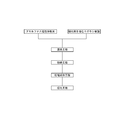
- FIG. 1 is a manufacturing process diagram.
- the amorphous metal powder, which is the magnetic material, and an epoxy resin in which the latent curing agent is already blended are prepared.
- the amorphous metal powder is previously adjusted by a classifier to particles that pass through an 80-mesh sieve and do not pass through a 325-mesh sieve.
- the amorphous metal powder and the epoxy resin are dry-mixed at a temperature not lower than the softening temperature of the epoxy resin and lower than the thermosetting start temperature.
- the amorphous metal powder and the epoxy resin are sufficiently mixed at room temperature using a blender or the like.
- the mixed mixture is put into a mixer such as a kneader and heated and mixed at the softening temperature (100 to 120 ° C.) of the epoxy resin.
- a mixer such as a kneader
- the softening temperature 100 to 120 ° C.
- an insulating film of epoxy resin is formed on the surface of the amorphous metal powder.
- the epoxy resin is uncured.
- the contents heated and mixed using a mixer such as a kneader are agglomerated cakes.
- the pulverization step is a step of obtaining a composite magnetic powder having an epoxy resin insulating film formed on the surface thereof by pulverizing and sieving the agglomerated cake at room temperature.
- the pulverization is preferably performed by a Henschel mixer, and the sieving is preferably performed with a particle size of 60 mesh.
- the mold used in the compression molding process may be a mold that can be cold-molded or warm-molded.
- cold molding refers to compression molding without applying temperature
- warm molding refers to compression molding for several minutes at a temperature of about the softening temperature (100 to 120 ° C.) of the epoxy resin.
- the density of the resin molding is improved by using warm molding.
- the magnetic core part has any one of a compacted magnetic body and a compacted magnet molded body (hereinafter referred to as a compacted magnetic body), in the compression molding process, the compact is contained in the mold. Holding the molded magnetic body or the like, the composite magnetic powder is disposed around the compacted magnetic body or the like and compression molded.
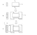
- FIG. 2 is a process diagram when insert-molding a compacted magnetic body or the like, and the left side of FIG. 2 represents an AA cross-sectional view on the right side of FIG.
- a compacted magnetic body 3 or the like is prepared (FIG. 2A).
- the compacted magnetic body 3 or the like is placed inside, and the composite magnetic powder 1a is placed around it and compressed in a mold (not shown) (FIG. 2B).
- the composite magnetic powder 1a is introduced so as to cover the whole of the compacted magnetic body 3 etc. and compressed in the mold (FIG. 2 (c)).
- the abutting surface 1b of the composite magnetic powder 1a is integrated in the compression molding process and the subsequent curing process.
- the molded product taken out from the mold is heated and cured at a temperature of 170 to 190 ° C. for 45 to 80 minutes. This is because if it is less than 170 ° C., it takes a long time to cure, and if it exceeds 190 ° C., deterioration starts.
- Heat curing is preferably performed in a nitrogen atmosphere. After the heat curing, the magnetic core component 1 is obtained by performing cutting, barrel processing, rust prevention treatment, and the like as necessary.
- the magnetic element of the present invention has an inductor function by winding a winding around the magnetic core component to form a coil.
- This magnetic element is incorporated in an electronic device circuit.
- a copper enameled wire can be used as the winding, and the types thereof are urethane wire (UEW), formal wire (PVF), polyester wire (PEW), polyesterimide wire (EIW), polyamideimide wire (AIW), A polyimide wire (PIW), a double coated wire combining these, a self-bonding wire, a litz wire, or the like can be used.
- a round wire or a square wire can be used as the cross-sectional shape of the copper enamel wire.
- As a coil winding method helical winding or toroidal winding can be adopted. In the case of an ultra-small magnetic core component, a cylindrical core, a square-shaped core, or a plate-shaped core other than the donut core used for the core of the toroidal coil can be used.
- the magnetic core component and / or magnetic element of the present invention as described above is a core component of a soft magnetic material used for power circuits, filter circuits, switching circuits, etc.
- a core component such as an inductor, a transformer, an antenna, a choke coil, a filter, or a magnetic element.
- it can be used as a magnetic core and a magnetic element for surface mounting components.
- Example 1 1940 g of amorphous metal magnetic powder (Fe—Si—B based amorphous metal) having a particle diameter of 150 ⁇ m or less and a median diameter D 50 of 50 ⁇ m and 60 g of epoxy resin powder containing dicyandiamide as a curing agent are mixed at room temperature for 10 minutes. did. This mixture was put into a kneader and heated and kneaded at 110 ° C. for 12 minutes. The blending ratio of the amorphous metal magnetic powder is 97% by mass. The cake agglomerated from the kneader was taken out and cooled, and then pulverized with a pulverizer to obtain a powder passing through a 60 mesh sieve.
- amorphous metal magnetic powder Fe—Si—B based amorphous metal
- a magnetic property measurement sample is shown in FIG.
- the sample for measuring magnetic characteristics is obtained by winding a 0.80 mm ⁇ polyester insulated copper enameled wire 2 around a flat cylindrical magnetic core component 30 for 30 to 35 turns so that an inductance value becomes 10 ⁇ H, thereby forming an inductor as a magnetic element. .
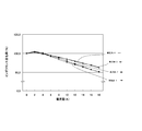
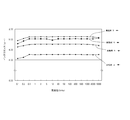
- the frequency dependence of the relative permeability was measured, and the inductance value when a direct current was superimposed on the coil was measured using an LCR meter at a measurement frequency of 1 KHz.
- Example 2 When the magnetic core part is compression molded using the amorphous metal magnetic powder and the epoxy resin powder obtained from the epoxy resin powder used in Example 1, the molding conditions are a temperature of 110 ° C. and a time of 5 minutes.
- a flat cylindrical magnetic core component having an inner diameter of 20 mm, an outer diameter of 30 mm, and a height of 5 mm was manufactured by thermosetting at 180 ° C. for 1 hour in the air atmosphere.
- the density of this magnetic core component was 5.17 g / cm 3 .
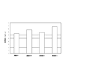
- Magnetic properties and mechanical properties of the obtained magnetic core parts were measured in the same manner as in Example 1. The results are shown in FIGS.
- Example 3 As an amorphous metal magnetic powder, 1940 g of an amorphous metal magnetic powder having a particle size distribution of 300 ⁇ m or less to which fine powder was added and 60 g of an epoxy resin powder containing dicyandiamide as a curing agent were mixed at room temperature for 10 minutes in a blender. . This mixture was put into a kneader and heated and kneaded at 110 ° C. for 12 minutes. The cake agglomerated from the kneader was taken out and cooled, and then pulverized by a pulverizer to obtain a powder passing through a 28 mesh sieve.
- Example 4 When the magnetic core part was compression molded using the powder passed through the 28-mesh sieve obtained from the amorphous metal magnetic powder and the epoxy resin powder used in Example 3, the molding conditions were a temperature of 110 ° C. and a time of 5 minutes.
- a flat cylindrical magnetic core component having an inner diameter of 20 mm, an outer diameter of 30 mm, and a height of 5 mm was manufactured by thermosetting under the conditions in the air atmosphere at 180 ° C. for 1 hour as in Example 3.
- the density of this magnetic core component was 5.33 g / cm 3 .
- Magnetic properties and mechanical properties of the obtained magnetic core parts were measured in the same manner as in Example 1. The results are shown in FIGS.
- Example 5 1960 g of amorphous metal magnetic powder (Fe—Si—B based amorphous metal) having a particle diameter of 150 ⁇ m or less and a median diameter D 50 of 50 ⁇ m and 40 g of epoxy resin powder containing dicyandiamide as a curing agent are mixed at room temperature for 10 minutes. did. This mixture was put into a kneader and heated and kneaded at 110 ° C. for 12 minutes. The blending ratio of the amorphous metal magnetic powder is 98% by mass. The cake agglomerated from the kneader was taken out and cooled, and then pulverized with a pulverizer to obtain a powder passing through a 60 mesh sieve.
- amorphous metal magnetic powder Fe—Si—B based amorphous metal
- compression molding was performed using a mold at a temperature of 110 ° C. for 5 minutes at a molding pressure of 2 t / cm 2 .
- the compression-molded product was taken out of the mold and thermally cured at 180 ° C. for 1 hour in an air atmosphere to produce a flat cylindrical magnetic core component having an inner diameter of 20 mm, an outer diameter of 30 mm, and a height of 5 mm. This magnetic core component could be used without breakage.
- amorphous metal magnetic powder Fe—Si—B based amorphous metal
- compression molding was performed using a mold at a temperature of 110 ° C. for 5 minutes at a molding pressure of 2 t / cm 2 .
- the compression-molded product was taken out of the mold and thermally cured at 180 ° C. for 1 hour in an air atmosphere to produce a flat cylindrical magnetic core component having an inner diameter of 20 mm, an outer diameter of 30 mm, and a height of 5 mm. This magnetic core component could be used without breakage.
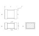
- Example 7 An example of a magnetic core component in which a ferrite core is insert-molded is shown in FIG. FIG. 7A is a plan view, FIG. 7B is a front view, and FIG. 7C is a cross-sectional view along the line AA.
- a ferrite core (not shown) is insert-molded inside.
- the powder passed through the 28 mesh screen obtained from the amorphous metal magnetic powder and the epoxy resin powder used in Example 3 was put into a mold, and then the ferrite core was placed so that the upper part was exposed, and the temperature was 110 ° C. And compression molding at a molding pressure of 2 t / cm 2 for 5 minutes.
- Example 3 Thereafter, the powder used in Example 3 was put into a mold so as to cover the entire ferrite core, and compression molded under conditions of a temperature of 110 ° C., a time of 5 minutes, and a molding pressure of 2 t / cm 2 . Heat-cured at 180 ° C. for 1 hour in air atmosphere, ferrite core is insert-molded, long diameter (t 1 ) 4.6 mm, short diameter (t 2 ) 3.06 mm, height (t 3 ) 2.36 mm magnetic core component 1 for chip inductor was manufactured.
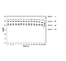
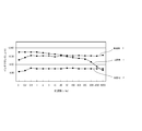
- a chip inductor was manufactured by winding 27 turns of 0.80 mm ⁇ polyester insulated copper enamel wire around the obtained magnetic core component 1 for chip inductor. The frequency dependence of the inductance was measured using this inductor. The results are shown in FIG.
- Comparative Example 1 A chip inductor having a magnetic core component having the same shape as in Example 7 was manufactured as a single ferrite product. The frequency dependency of inductance was measured under the same conditions as in Example 7. The results are shown in FIG.
- Comparative Example 2 A chip inductor having the same shape and material as in Example 7 was manufactured by injection molding. Injection molding was performed using 100 parts by mass of the amorphous metal powder used in Example 1 and 14 parts by mass of polyphenylene sulfide mixed therein. The frequency dependency of inductance was measured under the same conditions as in Example 7. The results are shown in FIG.
- Example 8 A chip inductor having the same shape as in Example 7 was manufactured using the same material and method as in Example 1 except that the ferrite core was not insert-molded. The frequency dependency of inductance was measured under the same conditions as in Example 7. The results are shown in FIG.
- Example 9 A magnetic core component for chip inductor in which a ferrite core was insert-molded by the same material and method as in Example 8 was manufactured again except that the chip inductor had the same shape as that of Example 7. The frequency dependency of inductance was measured under the same conditions as in Example 7. The results are shown in FIG.
- Example 10 A chip inductor having the same shape and material as in Example 7 was manufactured again. The frequency dependency of inductance was measured under the same conditions as in Example 7. The results are shown in FIG.
- the magnetic core component (amorphous powder magnetic core) of the present invention capable of obtaining high density and high magnetic permeability will be described.
- a mixed powder of amorphous metal powders having different particle sizes is used for the purpose of close packing, it is difficult to convey while maintaining the particle size distribution during the flow of the powder, and the gold from the hopper There was a problem that the particle size distribution changed greatly before being put into the mold.
- at least two types of amorphous metal powders having different average particle sizes and particle size distributions are granulated into secondary particles, and the secondary particles are compression-molded so that the particle size distribution does not change.
- An amorphous dust core having an amorphous powder core density of 5.6 or more and a relative magnetic permeability of 60 or more was obtained.
- the magnetic core component described below is based on such knowledge. This knowledge is also effective at the time of compression molding of amorphous metal powder in a magnetic core component containing the thermosetting binder resin.
- the amorphous metal powder that can be used in the present invention is a soft magnetic material, and as described above, an iron alloy type, a cobalt alloy type, a nickel alloy type, or a mixed alloy type amorphous metal powder thereof can be used.
- the oxide that forms the insulating coating on the particle surface of the amorphous metal powder includes an insulating metal or semi-metal oxide such as Al 2 O 3 , Y 2 O 3 , MgO, and ZrO 2 , glass, These mixtures are mentioned. Of these, glass materials are preferred. Among glass materials, low melting point glass is preferable. This is because it has a low softening temperature and can be fused to the soft magnetic amorphous alloy to coat its surface.
- the low melting point glass is not particularly limited as long as it does not react with the amorphous metal powder and softens at a temperature lower than the crystallization start temperature of the amorphous metal, preferably about 550 ° C. or less.
- Examples include known low melting points such as lead glass such as PbO—B 2 O 3 glass, P 2 O 5 glass, ZnO—BaO glass, and ZnO—B 2 O 3 —SiO 2 glass. Glass can be used.
- a lead-free glass, P 2 O 5 based glass providing a low softening point is preferred.
- P 2 O 5 is 60 to 80% by mass
- Al 2 O 3 is 10% by mass or less
- ZnO is 10 to 20% by mass
- Li 2 O is 10% by mass or less
- Na 2 O is 10% by mass.
- the following composition can be used.
- amorphous metal powder is coated with an inorganic insulating material to form an inorganic insulating layer.
- powder coating methods such as mechanofusion, and wet thin film manufacturing methods such as electroless plating and sol-gel methods.
- a dry thin film manufacturing method such as sputtering can be used.
- the powder coating method can be performed using, for example, a powder coating apparatus described in JP-A-2001-73062.
- the amorphous metal powder and the low-melting glass powder are subjected to a strong compressive frictional force, and the surface of the amorphous metal powder has a low melting point due to the fusion of the amorphous metal powder and the low-melting glass powder and the welding of the glass powders.
- An amorphous metal powder coated with an inorganic insulating layer made of glass can be obtained.
- the composition of the insulated amorphous metal powder is preferably 0.3 to 6% by weight of the inorganic insulating material, and more preferably 0.4 to 3% by weight of the inorganic insulating material so that the balance is amorphous metal powder. More preferably, the inorganic insulating material is 0.4 to 1% by weight so that the balance is amorphous metal powder, and the balance is amorphous metal powder. If necessary, 0.1 to 0.5% by weight of a stearate lubricant such as zinc stearate or calcium stearate may be added. Moreover, warm molding, metal mold
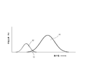
- FIG. 10 shows the distribution of the two types of insulated amorphous metal powders.
- FIG. 10 is a particle size distribution diagram of insulated amorphous metal powders each having a normal distribution. The average particle diameter is represented by a peak. As shown in FIG. 10, it is preferable to prepare insulated amorphous metal powders 11 and 12 having distinctly different peaks in a particle size distribution diagram where the abundance ratio is on the vertical axis and the particle diameter is on the horizontal axis.
- two kinds of large and small insulated amorphous metal powders 11 and 12 having an overlapping portion 13 of at least 10% or less are prepared.
- 10% is an area in a range where the distribution overlaps with respect to the area of the entire peak clearly including the overlapping part. is there.
- the preferred average particle size of the amorphous metal powder 11 having a large average particle size in the present invention is 40 ⁇ m to 100 ⁇ m, and the preferred average particle size of the amorphous metal powder 2 having a small average particle size is 1 ⁇ m to 10 ⁇ m.
- the blending ratio of the amorphous metal powder 1 and the amorphous metal powder 12 is preferably 18 to 55 parts by mass of the amorphous metal powder 2 when the amorphous metal powder 1 is 100 parts by mass.
- the two kinds of powders are mixed and granulated to obtain secondary particles.
- the granulation is carried out by using a self-supporting granulation method such as rolling fluid granulation, a forced granulation method such as spray drying, or the like, preferably using a rolling fluid granulation method.
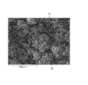
- the state of the secondary particles after granulation is shown in FIG. Secondary particles are obtained in which amorphous metal powder 12 having a small particle diameter is attached around amorphous metal powder 11 having a large average particle diameter.
- a binder may be attached if necessary.
- the binder it is preferable to use polyvinyl alcohol, polyvinyl butyral, hydroxypropylcellulose, or hydroxypropylmethylcellulose. The above-mentioned components may be modified.
- the secondary particles are filled into a predetermined mold and compression molded.
- the secondary particle powder can be filled in a mold, press-molded at a predetermined pressure, and the molded green compact is fired to burn the resin and obtain a fired body.
- the firing temperature needs to be lower than the crystallization start temperature of the amorphous metal powder.
- the obtained amorphous dust core has an density of 5.6 or more and an amorphous dust core having a relative permeability at 1 kHz of 60 or more, preferably 65 or more, more preferably 70 or more.
- Example 11 (Fe 0.97 Cr 0.03 ) 76 (Si 0.5 B 0.2 ) 22 C 2 amorphous metal powder and low melting point glass powder (P 2 O 5 is 60 to 80 mass%, Al 2 O 3 is 10 mass% or less, ZnO is 10 ⁇ 20% by mass, Li 2 O is 10% by mass or less, Na 2 O is 10% by mass or less, and the particle size is 40 ⁇ m or less).
- Zinc stearate was used as a lubricant.
- the Fe—Cr—Si—B—C amorphous metal alloy powder was prepared by adjusting the average particle size to 40 ⁇ m to 100 ⁇ m with a sieve.
- Fe—Cr—Si—B—C amorphous metal alloy powders with different particle sizes were prepared and the average particle size was adjusted to 1 ⁇ m to 10 ⁇ m.
- the secondary particles were granulated by rolling fluid granulation method by blending 18 parts by mass of the amorphous metal alloy powder having a small particle diameter with 100 parts by mass of the prepared amorphous metal alloy powder having a large particle diameter.
- the composite powder was obtained by adding 0.6 parts by mass of zinc stearate to 100 parts by mass of the secondary particle powder and mixing at a temperature of 112 ° C. using a ball mill.
- the composite powder After the composite powder is filled in the mold, it is press-molded at a predetermined pressure to obtain a green compact, and then the green compact is baked at 480 ° C. for 15 minutes in the air atmosphere to burn out the resin. 10 mm in diameter, 5 mm in inner diameter, and 5 mm in thickness).
- the density of the obtained amorphous powder magnetic core was calculated from the size and weight by geometric measurement. Further, the magnetic permeability was measured as the magnetic permeability at 1 kHz according to JIS C2561. The results are shown in Table 1.
- Example 12 Example 11 except that 25 parts by mass of the amorphous metal alloy powder with a small particle size was blended with 100 parts by mass of the amorphous metal alloy powder with a large particle size, and the secondary particles were granulated by the tumbling flow granulation method. In the same manner, an amorphous powder magnetic core was obtained. The density and magnetic permeability were measured in the same manner as in Example 11. The results are shown in Table 1.
- Example 13 Example 11 except that 45 parts by mass of the amorphous metal alloy powder having a small particle diameter was blended with 100 parts by mass of the amorphous metal alloy powder having a large particle diameter, and the secondary particles were granulated by a rolling fluid granulation method. In the same manner, an amorphous powder magnetic core was obtained. The density and magnetic permeability were measured in the same manner as in Example 11. The results are shown in Table 1.
- Example 14 Example 11 except that 55 parts by mass of the amorphous metal alloy powder having a small particle diameter was blended with 100 parts by mass of the amorphous metal alloy powder having a large particle diameter, and the secondary particles were granulated by the rolling fluid granulation method. In the same manner, an amorphous powder magnetic core was obtained. The density and magnetic permeability were measured in the same manner as in Example 11. The results are shown in Table 1.
- Comparative Example 3 An amorphous powder magnetic core was obtained in the same manner as in Example 11 using only the amorphous metal alloy powder adjusted to a particle size of 50 ⁇ m. The density and magnetic permeability were measured in the same manner as in Example 11. The results are shown in Table 1.
- the magnetic core component of the present invention can be used for electronic devices that will be reduced in size and weight in the future because the magnetic core component can be reduced in size by using amorphous metal powder. Moreover, since the magnetic core component (amorphous dust core) of the present invention can increase the density and the magnetic permeability, it can be used for various electric and electronic devices in the future.
Landscapes
- Engineering & Computer Science (AREA)
- Chemical & Material Sciences (AREA)
- Power Engineering (AREA)
- Mechanical Engineering (AREA)
- Materials Engineering (AREA)
- Metallurgy (AREA)
- Organic Chemistry (AREA)
- Manufacturing & Machinery (AREA)
- Crystallography & Structural Chemistry (AREA)
- Dispersion Chemistry (AREA)
- Soft Magnetic Materials (AREA)
- Powder Metallurgy (AREA)
Abstract
La présente invention porte sur un composant à noyau magnétique dans lequel : aucun défaut tel que des fissures n'apparaît, même si celui-ci contient au moins 90 % en masse de poudre métallique amorphe ; et une résistance mécanique suffisante peut être obtenue. Le composant à noyau magnétique comprend au moins une poudre magnétique, choisie parmi une poudre métallique amorphe simple et une poudre métallique amorphe revêtue d'un matériau isolant, et un liant résineux thermodurcissable qui ont été durcis à la chaleur et moulés ; et est caractérisé par le fait qu'il contient de 90 % à 99 % en masse de poudre magnétique, par rapport au contenu total de poudre magnétique et de liant résineux thermodurcissable.
Priority Applications (3)
| Application Number | Priority Date | Filing Date | Title |
|---|---|---|---|
| EP15768981.1A EP3131100A4 (fr) | 2014-03-25 | 2015-03-25 | Composant à noyau magnétique, élément magnétique, et procédé de fabrication de composant à noyau magnétique |
| CN201580015772.5A CN106165028A (zh) | 2014-03-25 | 2015-03-25 | 磁性芯部件和磁性元件、以及磁性芯部件的制造方法 |
| US15/129,320 US20170098499A1 (en) | 2014-03-25 | 2015-03-25 | Magnetic core part, magnetic element, and method for producing magnetic core part |
Applications Claiming Priority (4)
| Application Number | Priority Date | Filing Date | Title |
|---|---|---|---|
| JP2014062230A JP2015185758A (ja) | 2014-03-25 | 2014-03-25 | アモルファス圧粉磁心とその製造方法 |
| JP2014062781A JP2015185776A (ja) | 2014-03-25 | 2014-03-25 | 磁性コア部品および磁性素子、ならびに磁性コア部品の製造方法 |
| JP2014-062230 | 2014-03-25 | ||
| JP2014-062781 | 2014-03-25 |
Publications (1)
| Publication Number | Publication Date |
|---|---|
| WO2015147064A1 true WO2015147064A1 (fr) | 2015-10-01 |
Family
ID=54195575
Family Applications (1)
| Application Number | Title | Priority Date | Filing Date |
|---|---|---|---|
| PCT/JP2015/059145 Ceased WO2015147064A1 (fr) | 2014-03-25 | 2015-03-25 | Composant à noyau magnétique, élément magnétique, et procédé de fabrication de composant à noyau magnétique |
Country Status (4)
| Country | Link |
|---|---|
| US (1) | US20170098499A1 (fr) |
| EP (1) | EP3131100A4 (fr) |
| CN (1) | CN106165028A (fr) |
| WO (1) | WO2015147064A1 (fr) |
Cited By (2)
| Publication number | Priority date | Publication date | Assignee | Title |
|---|---|---|---|---|
| JP2019504492A (ja) * | 2015-12-17 | 2019-02-14 | コミッサリア ア レネルジー アトミーク エ オ ゼネルジ ザルタナテイヴ | 低磁気損失を示すインダクタコア |
| CN116099983A (zh) * | 2021-11-10 | 2023-05-12 | 重庆大学 | 一种磁力结合的3d打印方法 |
Families Citing this family (15)
| Publication number | Priority date | Publication date | Assignee | Title |
|---|---|---|---|---|
| JP6580817B2 (ja) | 2014-09-18 | 2019-09-25 | Ntn株式会社 | 磁性コアの製造方法 |
| JP7059593B2 (ja) * | 2017-01-12 | 2022-04-26 | Tdk株式会社 | 軟磁性材料、コア及びインダクタ |
| CN106903319A (zh) * | 2017-02-20 | 2017-06-30 | 歌尔股份有限公司 | 一种多层球形材料及其制备方法 |
| CN107452494B (zh) * | 2017-07-28 | 2018-11-27 | 天津大学 | 实现多磁导率连续变化环形磁芯电感的装置及方法 |
| CN107749340A (zh) * | 2017-10-17 | 2018-03-02 | 深圳顺络电子股份有限公司 | 一种高可靠性大电流模压电感及制造方法 |
| JP6867966B2 (ja) * | 2018-03-09 | 2021-05-12 | Tdk株式会社 | 軟磁性合金粉末、圧粉磁心および磁性部品 |
| JP6858158B2 (ja) * | 2018-06-13 | 2021-04-14 | 株式会社タムラ製作所 | コア、リアクトル、コアの製造方法及びリアクトルの製造方法 |
| WO2020246246A1 (fr) | 2019-06-04 | 2020-12-10 | 昭和電工マテリアルズ株式会社 | Composé, article moulé et produit durci |
| JP7307603B2 (ja) * | 2019-06-20 | 2023-07-12 | 株式会社タムラ製作所 | 圧粉磁心及び圧粉磁心の製造方法 |
| JP7298568B2 (ja) * | 2020-08-25 | 2023-06-27 | 株式会社村田製作所 | 磁性粉の製造方法および圧粉成形体の製造方法 |
| CN112309701B (zh) * | 2020-09-28 | 2022-05-06 | 海宁市海铖电子有限公司 | 一种磁芯成型模具 |
| WO2022077150A1 (fr) * | 2020-10-12 | 2022-04-21 | 昆山磁通新材料科技有限公司 | Matériau composite magnétique et son procédé de préparation, et inductance et son procédé de fabrication |
| WO2022118470A1 (fr) * | 2020-12-04 | 2022-06-09 | 昭和電工マテリアルズ株式会社 | Pâte |
| US20220331859A1 (en) * | 2021-04-14 | 2022-10-20 | Cyntec Co., Ltd. | Mixture for forming a multilayer inductor and the fabrication method thereof |
| CN114974872A (zh) * | 2022-06-21 | 2022-08-30 | 苏州锦鳞电子科技有限公司 | 模压电感及其制作方法 |
Citations (6)
| Publication number | Priority date | Publication date | Assignee | Title |
|---|---|---|---|---|
| JPH04254305A (ja) * | 1991-02-06 | 1992-09-09 | Matsushita Electric Ind Co Ltd | 複合軟磁性体の製造方法 |
| WO2005015581A1 (fr) * | 2003-08-06 | 2005-02-17 | Nippon Kagaku Yakin Co., Ltd. | Poudre composite faiblement magnetique et procede de production associe, et procede de production d'un produit compact faiblement magnetique |
| WO2006022262A1 (fr) * | 2004-08-23 | 2006-03-02 | Nippon Kagaku Yakin Co., Ltd. | Procédé de fabrication d'un composant de noyau magnétique |
| JP2012044156A (ja) * | 2010-07-23 | 2012-03-01 | Toyota Central R&D Labs Inc | 圧粉磁心の製造方法および磁心用粉末の製造方法 |
| JP2012077363A (ja) * | 2010-10-05 | 2012-04-19 | Sumitomo Electric Ind Ltd | 冶金用粉末の製造方法および圧粉磁心の製造方法 |
| JP2013213247A (ja) * | 2012-03-30 | 2013-10-17 | Seiko Epson Corp | 軟磁性粉末、圧粉磁心および磁性素子 |
Family Cites Families (10)
| Publication number | Priority date | Publication date | Assignee | Title |
|---|---|---|---|---|
| TW428183B (en) * | 1997-04-18 | 2001-04-01 | Matsushita Electric Industrial Co Ltd | Magnetic core and method of manufacturing the same |
| TW200419600A (en) * | 2002-12-06 | 2004-10-01 | Toko Inc | Complex magnetic material, and core and magnetic element using the complex magnetic material |
| JP2007134591A (ja) * | 2005-11-11 | 2007-05-31 | Nec Tokin Corp | 複合磁性材料とそれを用いた圧粉磁芯および磁性素子 |
| JPWO2010084812A1 (ja) * | 2009-01-22 | 2012-07-19 | 住友電気工業株式会社 | 冶金用粉末の製造方法、圧粉磁心の製造方法、圧粉磁心およびコイル部品 |
| JP5605550B2 (ja) * | 2010-06-16 | 2014-10-15 | 住友電気工業株式会社 | リアクトル及びその製造方法 |
| CN102737802A (zh) * | 2012-07-02 | 2012-10-17 | 浙江嘉康电子股份有限公司 | 线圈磁粉一体成型式电感及其制作方法 |
| JP6159512B2 (ja) * | 2012-07-04 | 2017-07-05 | 太陽誘電株式会社 | インダクタ |
| JP6062676B2 (ja) * | 2012-07-25 | 2017-01-18 | Ntn株式会社 | 複合磁性コアおよび磁性素子 |
| JP5516828B1 (ja) * | 2012-07-25 | 2014-06-11 | 東レ株式会社 | プリプレグおよび炭素繊維強化複合材料 |
| KR101470513B1 (ko) * | 2013-07-17 | 2014-12-08 | 주식회사 아모그린텍 | 대전류 직류중첩특성 및 코어손실 특성이 우수한 연자성 코어 및 그의 제조방법 |
-
2015
- 2015-03-25 CN CN201580015772.5A patent/CN106165028A/zh active Pending
- 2015-03-25 US US15/129,320 patent/US20170098499A1/en not_active Abandoned
- 2015-03-25 EP EP15768981.1A patent/EP3131100A4/fr not_active Withdrawn
- 2015-03-25 WO PCT/JP2015/059145 patent/WO2015147064A1/fr not_active Ceased
Patent Citations (6)
| Publication number | Priority date | Publication date | Assignee | Title |
|---|---|---|---|---|
| JPH04254305A (ja) * | 1991-02-06 | 1992-09-09 | Matsushita Electric Ind Co Ltd | 複合軟磁性体の製造方法 |
| WO2005015581A1 (fr) * | 2003-08-06 | 2005-02-17 | Nippon Kagaku Yakin Co., Ltd. | Poudre composite faiblement magnetique et procede de production associe, et procede de production d'un produit compact faiblement magnetique |
| WO2006022262A1 (fr) * | 2004-08-23 | 2006-03-02 | Nippon Kagaku Yakin Co., Ltd. | Procédé de fabrication d'un composant de noyau magnétique |
| JP2012044156A (ja) * | 2010-07-23 | 2012-03-01 | Toyota Central R&D Labs Inc | 圧粉磁心の製造方法および磁心用粉末の製造方法 |
| JP2012077363A (ja) * | 2010-10-05 | 2012-04-19 | Sumitomo Electric Ind Ltd | 冶金用粉末の製造方法および圧粉磁心の製造方法 |
| JP2013213247A (ja) * | 2012-03-30 | 2013-10-17 | Seiko Epson Corp | 軟磁性粉末、圧粉磁心および磁性素子 |
Non-Patent Citations (1)
| Title |
|---|
| See also references of EP3131100A4 * |
Cited By (3)
| Publication number | Priority date | Publication date | Assignee | Title |
|---|---|---|---|---|
| JP2019504492A (ja) * | 2015-12-17 | 2019-02-14 | コミッサリア ア レネルジー アトミーク エ オ ゼネルジ ザルタナテイヴ | 低磁気損失を示すインダクタコア |
| US11309109B2 (en) | 2015-12-17 | 2022-04-19 | Commissariat A L'energie Atomique Et Aux Energies Alternatives | Inductive core exhibiting low magnetic losses |
| CN116099983A (zh) * | 2021-11-10 | 2023-05-12 | 重庆大学 | 一种磁力结合的3d打印方法 |
Also Published As
| Publication number | Publication date |
|---|---|
| CN106165028A (zh) | 2016-11-23 |
| EP3131100A4 (fr) | 2018-04-18 |
| US20170098499A1 (en) | 2017-04-06 |
| EP3131100A1 (fr) | 2017-02-15 |
Similar Documents
| Publication | Publication Date | Title |
|---|---|---|
| WO2015147064A1 (fr) | Composant à noyau magnétique, élément magnétique, et procédé de fabrication de composant à noyau magnétique | |
| US10204725B2 (en) | Composite magnetic core and magnetic element | |
| JP2020095988A (ja) | 圧粉磁心 | |
| JP2017135342A (ja) | アモルファス磁性コアおよび磁性素子、ならびに磁性コアの製造方法 | |
| JP7128439B2 (ja) | 圧粉磁芯およびインダクタ素子 | |
| CN111724964B (zh) | 磁性体芯及线圈部件 | |
| JP4358743B2 (ja) | ボンド磁石の製造方法及びボンド磁石を備えた磁気デバイスの製造方法 | |
| WO2014091589A1 (fr) | Dispositif magnétique, élément pour appliquer une polarisation magnétique ainsi que procédé de fabrication d'un élément pour appliquer une polarisation magnétique | |
| JP2015185758A (ja) | アモルファス圧粉磁心とその製造方法 | |
| JPWO2020145047A1 (ja) | 圧粉磁心の製造方法、圧粉磁心、コイル部品および造粒粉 | |
| JP6314020B2 (ja) | ナノ結晶軟磁性合金粉末を用いた圧粉磁芯とその製造方法 | |
| JP2015185776A (ja) | 磁性コア部品および磁性素子、ならびに磁性コア部品の製造方法 | |
| JP2020174127A (ja) | インダクタ素子 | |
| TWI751616B (zh) | 用於製作感應組件的方法及感應組件 | |
| US11569014B2 (en) | Dust core and inductor element | |
| JP2019029676A (ja) | アモルファス磁性コアおよび磁性素子 | |
| US10923258B2 (en) | Dust core and inductor element | |
| JP2017135341A (ja) | アモルファス磁性コアおよび磁性素子、ならびに磁性コアの製造方法 | |
| JPH11260617A (ja) | 圧粉磁芯、その製造方法、および巻線部品 | |
| JP2019029675A (ja) | アモルファス磁性コアおよび磁性素子 | |
| JP2008235497A (ja) | 圧粉磁芯及びそれを用いたインダクタ | |
| JP2026043865A (ja) | 磁性体材料、圧粉磁心及びコイル製品並びに磁性体材料の製造方法 | |
| JP2018101686A (ja) | 軟磁性合金粉末 |
Legal Events
| Date | Code | Title | Description |
|---|---|---|---|
| 121 | Ep: the epo has been informed by wipo that ep was designated in this application |
Ref document number: 15768981 Country of ref document: EP Kind code of ref document: A1 |
|
| NENP | Non-entry into the national phase |
Ref country code: DE |
|
| WWE | Wipo information: entry into national phase |
Ref document number: 15129320 Country of ref document: US |
|
| REEP | Request for entry into the european phase |
Ref document number: 2015768981 Country of ref document: EP |
|
| WWE | Wipo information: entry into national phase |
Ref document number: 2015768981 Country of ref document: EP |