WO2015151575A1 - 自動二輪車のタンデムグリップ・ユニット - Google Patents
自動二輪車のタンデムグリップ・ユニット Download PDFInfo
- Publication number
- WO2015151575A1 WO2015151575A1 PCT/JP2015/053053 JP2015053053W WO2015151575A1 WO 2015151575 A1 WO2015151575 A1 WO 2015151575A1 JP 2015053053 W JP2015053053 W JP 2015053053W WO 2015151575 A1 WO2015151575 A1 WO 2015151575A1
- Authority
- WO
- WIPO (PCT)
- Prior art keywords
- supported
- tandem
- grip unit
- case
- tandem grip
- Prior art date
- Legal status (The legal status is an assumption and is not a legal conclusion. Google has not performed a legal analysis and makes no representation as to the accuracy of the status listed.)
- Ceased
Links
Images


Classifications
-
- B—PERFORMING OPERATIONS; TRANSPORTING
- B62—LAND VEHICLES FOR TRAVELLING OTHERWISE THAN ON RAILS
- B62J—CYCLE SADDLES OR SEATS; AUXILIARY DEVICES OR ACCESSORIES SPECIALLY ADAPTED TO CYCLES AND NOT OTHERWISE PROVIDED FOR, e.g. ARTICLE CARRIERS OR CYCLE PROTECTORS
- B62J7/00—Luggage carriers
- B62J7/02—Luggage carriers characterised by the arrangement thereof on cycles
- B62J7/04—Luggage carriers characterised by the arrangement thereof on cycles arranged above or behind the rear wheel
-
- B—PERFORMING OPERATIONS; TRANSPORTING
- B62—LAND VEHICLES FOR TRAVELLING OTHERWISE THAN ON RAILS
- B62J—CYCLE SADDLES OR SEATS; AUXILIARY DEVICES OR ACCESSORIES SPECIALLY ADAPTED TO CYCLES AND NOT OTHERWISE PROVIDED FOR, e.g. ARTICLE CARRIERS OR CYCLE PROTECTORS
- B62J25/00—Foot-rests; Knee grips; Passenger hand-grips
- B62J25/08—Passengers hand-grips
-
- B—PERFORMING OPERATIONS; TRANSPORTING
- B62—LAND VEHICLES FOR TRAVELLING OTHERWISE THAN ON RAILS
- B62J—CYCLE SADDLES OR SEATS; AUXILIARY DEVICES OR ACCESSORIES SPECIALLY ADAPTED TO CYCLES AND NOT OTHERWISE PROVIDED FOR, e.g. ARTICLE CARRIERS OR CYCLE PROTECTORS
- B62J9/00—Containers specially adapted for cycles, e.g. panniers or saddle bags
- B62J9/20—Containers specially adapted for cycles, e.g. panniers or saddle bags attached to the cycle as accessories
- B62J9/23—Containers specially adapted for cycles, e.g. panniers or saddle bags attached to the cycle as accessories above or alongside the rear wheel
-
- B—PERFORMING OPERATIONS; TRANSPORTING
- B62—LAND VEHICLES FOR TRAVELLING OTHERWISE THAN ON RAILS
- B62J—CYCLE SADDLES OR SEATS; AUXILIARY DEVICES OR ACCESSORIES SPECIALLY ADAPTED TO CYCLES AND NOT OTHERWISE PROVIDED FOR, e.g. ARTICLE CARRIERS OR CYCLE PROTECTORS
- B62J9/00—Containers specially adapted for cycles, e.g. panniers or saddle bags
- B62J9/20—Containers specially adapted for cycles, e.g. panniers or saddle bags attached to the cycle as accessories
- B62J9/24—Containers specially adapted for cycles, e.g. panniers or saddle bags attached to the cycle as accessories on specially adapted racks, e.g. for top or side cases
-
- B—PERFORMING OPERATIONS; TRANSPORTING
- B62—LAND VEHICLES FOR TRAVELLING OTHERWISE THAN ON RAILS
- B62J—CYCLE SADDLES OR SEATS; AUXILIARY DEVICES OR ACCESSORIES SPECIALLY ADAPTED TO CYCLES AND NOT OTHERWISE PROVIDED FOR, e.g. ARTICLE CARRIERS OR CYCLE PROTECTORS
- B62J9/00—Containers specially adapted for cycles, e.g. panniers or saddle bags
- B62J9/20—Containers specially adapted for cycles, e.g. panniers or saddle bags attached to the cycle as accessories
- B62J9/27—Containers specially adapted for cycles, e.g. panniers or saddle bags attached to the cycle as accessories characterised by mounting arrangements, e.g. quick release arrangements
Definitions
- the present invention is a passenger mounted on a motorcycle in which an article storage panya is detachably attached to the left and right sides of the rear part of the vehicle body, and a top case for article storage is detachably attached to the upper part of the vehicle body rear part. Relates to a tandem grip unit including a pair of left and right tandem grips.
- Some motorcycles are provided with a pair of left and right tandem grips held by the passenger under the passenger seat at the rear of the motorcycle.
- the tandem grip is generally supported at the rear portion of the vehicle body frame (for example, Patent Document 1).
- An object of the present invention is to provide a tandem grip unit capable of attaching a pannier and a top case without complicating a rear structure of a body frame of a motorcycle.
- the tandem grip unit of the present invention has an article storage panya detachably attached to the left and right sides of the rear part of the vehicle body, and an article storage top case attached to the upper part of the vehicle body rear part.
- a tandem grip unit including a pair of left and right tandem grips held by a passenger in a motorcycle that can be attached, each tandem grip being supported by a vehicle body frame and a grip held by the passenger
- a molded product in which a part, a pannier attaching part to which the pannier is attached, and a case attaching part to which the top case is attached are integrally formed.
- each of the left and right tandem grips includes a supported portion supported by the vehicle body frame, a grip portion gripped by the passenger, a pannier mounting portion to which the panya is mounted, and a case mounting to which the top case is mounted. Since the parts are integrally formed, the panya and the top case can be attached without complicating the rear structure of the vehicle body frame. Further, by forming the supported portion, the grip portion, the pannier attachment portion, and the case attachment portion integrally, the number of parts can be reduced, and the tandem grip unit is increased in size and the rigidity is improved. As a result, the panya and the top case can be stably supported.
- a rope hook for locking the loading rope is integrally formed. According to this configuration, since the rope hook is also integrally formed by molding, the number of parts can be further reduced. In addition, the large tandem grip unit can stably support the loader and the load.
- the case attaching portion is a boss provided at a rear end portion of the tandem grip, and a long case stay that extends in the front-rear direction and supports the top case is detachable from the boss. It is preferable that it is attached. According to this configuration, it is possible to reduce the size of the case mounting portion, and when the top case is not mounted, the appearance of the rear portion of the vehicle body is improved by removing the case stay.
- each tandem grip has a long base portion having a longitudinal direction in the front-rear direction, a long upper portion disposed in the front-rear direction disposed above the base portion, and extends upward from the front-rear end portions of the base portion.
- a pair of connecting portions spaced in the front-rear direction connecting the front and rear end portions of the base portion and the front and rear end portions of the upper portion, and the supported portion is formed on a surface facing the vehicle body inside of the base portion, and the vehicle body of the base portion
- the pannier mounting portion is formed on the surface facing outward, the portion between the connecting portions in the upper portion forms the grip portion, and the case mounting portion is formed in the rear end portion of the upper portion. Is preferred. According to this configuration, a space can be formed between the pair of connecting portions below the grip portion. This space makes it easier for the passenger to grip the grip portion and reduces the weight of the tandem grip unit.
- the supported portion When a supported portion is formed on the base portion, the supported portion includes first and second supported portions provided at a front end portion and a rear end portion of a surface of the base portion facing the vehicle body, and the base portion.
- a third supported part provided in the middle part in the front-rear direction, the first and second supported parts are fixed by bolts from above and below, and the third supported part from the left and right direction It is preferable to be fixed with bolts.
- the tandem grip unit can be applied to many types of motorcycles by setting the mounting direction of the tandem grip unit to the vehicle body frame in the horizontal direction and the vertical direction.
- the vehicle body frame includes a main frame that forms a front half and a rear frame that forms a rear half, and the rear frame A pair of rear frame pieces; a rear end cross member that connects a rear end portion of the pair of rear frames; and an intermediate cross member that connects the pair of rear frames in front of the pair of rear frame pieces;
- a first boss for supporting the first supported portion is provided in front of the cross member, and a second boss for supporting the second supported portion is provided in the vicinity of the rear end cross member in the rear frame.
- a third boss is provided on the outer side of the intermediate cross member in the rear frame to support the third supported portion.
- the second boss is provided in the vicinity of the rear end cross member and the third boss is provided on the outer side of the intermediate cross member, the rigidity of the second and third bosses is improved. Therefore, the support of the second and third supported parts is stabilized.
- a motorcycle according to the present invention includes the tandem grip unit according to the present invention and a tail cover that is detachably attached to a rear end portion of the body frame and covers the body frame from the outside.
- the grip portion and the pannier attachment portion are exposed to the outside from the tail cover, and the other portions are covered with the tail cover from the outside.
- a part of the tandem grip unit for example, the supported portion can be hidden by the tail cover.
- the appearance of the rear part of the vehicle body is improved and the supported part does not become an exposed design part, so that the manufacturing cost of the tandem grip unit can be reduced.
- the tail cover is detachable, it is possible to form a model in which the supported portion is formed as a design part and the tail cover is removed. Thereby, the freedom degree of design improves.
- Another motorcycle according to the present invention includes a tandem grip unit according to the present invention, the pannier attached to each tandem grip, a case stay attached to a pair of case attaching portions, and a pair of case stays. And a support plate attached between the top case and the top case supported by the support plate. Accordingly, the panya and the top case can be attached without complicating the rear structure of the body frame of the motorcycle.
- FIG. 1 is a side view showing a rear portion of a motorcycle including a tandem grip unit according to an embodiment of the present invention. It is a perspective view which shows the state which attached the same tandem grip unit to the vehicle body frame.
- FIG. 3 is a plan view of FIG. 2. It is the top view which attached the tail cover to the top view of FIG. It is the top view which attached the case stay to the top view of FIG. It is the top view which attached the support plate to the top view of FIG.
- Fig. 2 is a perspective view showing a rear portion of the motorcycle.
- FIG. 1 is a side view of a rear portion of a motorcycle including a tandem grip unit according to an embodiment of the present invention.
- the body frame FR of the motorcycle has a main frame 1 constituting the front half part and a rear frame 2 connected to the rear part of the main frame 1 and constituting the rear part of the body frame FR.
- a front wheel is supported on a front end portion of the main frame 1 via a front fork (not shown).
- a swing arm bracket 4 is provided at the lower end of the rear end of the main frame 1, and a swing arm 8 is supported on the swing arm bracket 4 via a pivot shaft 6 at the front end portion so as to be swingable up and down.
- a rear wheel 10 is supported at the rear end of the swing arm 8.
- An engine E is supported at the lower center of the main frame 1, and the rear wheels 10 are driven by the engine E.
- the engine E is, for example, a parallel multi-cylinder four-cycle engine.
- a rider's seat 12 and a passenger's seat 14 are supported on the rear frame 2. Below the rider's seat 14, there is disposed one rear wheel suspension device 16 that is connected between the main frame 1 and the swing arm 8 and that faces substantially in the front-rear direction. Below the rider's seat 12 in the rear frame 2 is a first foot step 18 that is a rider's footrest, and behind that is a step that supports a second footstep 19 that is a rider's footrest. A stay 20 is attached. A pair of left and right foot steps 18, 19 and a step stay 20 are provided.
- a tandem grip unit 24 including a pair of left and right tandem grips 22 held by the passenger is attached to the rear frame 2 below the passenger seat 14.
- Panniers 26 for storing articles are disposed on the left and right sides of the rear part of the vehicle body, and are detachably attached to the rear frame 2 via a tandem grip unit 24.
- a top case 28 for storing articles is disposed at the upper part of the rear end of the vehicle body, and is detachably attached to the rear frame 2 via a tandem grip unit 24.
- the top case 28 is attached to the tandem grip unit 24 via a case stay 70 and a support plate 72 described later.
- a resin tail cover 30 that covers the rear frame 2 from the outside is supported at the rear end of the rear frame 2.
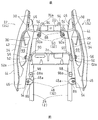
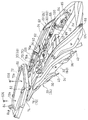
- FIG. 2 is a perspective view of the tandem grip unit 24 attached to the rear frame 2 as seen obliquely from above and FIG. 3 is a plan view thereof.
- a rear end cross member 2b for connecting the rear frame pieces 2a, 2a is joined to the rear end portions of the pair of left and right rear frame pieces 2a, and further, the rear frame pieces 2a, 2a, An intermediate cross member 2c that connects 2a is joined.
- the left and right tandem grips 22, 22 of the tandem grip unit 24 are symmetrical.
- each tandem grip 22 is made of aluminum die cast.
- each tandem grip 22 includes a supported portion 32 supported by the rear frame 2, a grip portion 34 held by a passenger, and a pannier attachment portion 36 to which a pannier 26 (FIG. 1) is attached.
- This is a molded product in which a case attaching portion 38 to which the top case 28 (FIG. 1) is attached and a rope hook 40 for locking the loading rope are integrally formed.
- each tandem grip 22 includes a long base portion 42 having a longitudinal direction in the front-rear direction, a long upper portion 44 disposed above the base portion 42, and upward from the front and rear end portions of the base portion 42.
- a pair of connecting portions 46 extending in the front-rear direction and connecting the front and rear end portions of the base portion 42 and the front and rear end portions of the upper portion 44 are provided. That is, in the tandem grip 22, a space 69 that is long in the front-rear direction penetrating in the left-right direction and surrounded by the base portion 42, the upper portion 44, and the front and rear connection portions 46, 46 is formed.
- the supported portion 32 is formed on the surface of the base portion 42 facing the vehicle body.
- the supported portion 32 is provided at first and second supported portions 48 and 50 provided at the front end portion and the rear end portion of the surface of the base portion 42 facing the vehicle body, and at the intermediate portion in the front-rear direction of the base portion 42.
- a third supported portion 52 is fixed by bolts 54 from the vertical direction
- the third supported portion 52 is fixed by bolts 56 from the left and right directions.
- the first supported portion 48 includes a first mounting piece 48 that protrudes inward from the front end portion of the surface of the base portion 42 facing the inner side of the vehicle body.
- a through hole 48 a facing upward is formed in 48.
- the second supported portion 50 includes a second mounting piece 50 that protrudes inward from the rear end portion of the base 42 facing the vehicle body, and a through-hole 50 a that faces upward is formed in the second mounting piece 50.
- the third supported portion 52 is composed of a boss provided at the intermediate portion in the front-rear direction of the base portion 42, and a bolt insertion hole 52 a facing the left-right direction is formed in the boss 52.
- the third supported portion 52 is provided on the surface of the base portion 42 facing the vehicle body inside and protrudes inward.
- the pannier mounting portion 36 is formed on the surface of the base portion 42 facing the outside of the vehicle body.
- the pannier mounting portion 36 is provided at the front end portion and the rear end portion of the surface of the base portion 42 facing the outside of the vehicle body, and includes a bottomed recess recessed into the vehicle body inside.
- the pannier mounting portion 36 is configured according to the structure of the mounted portion of the panya 26 (FIG. 1), and is not limited to the structure of the present embodiment.
- the portion between the front and rear connecting portions 46, 46 in the upper portion 44 of the tandem grip 22 constitutes the grip portion 34.
- the case attaching portion 38 is formed at the rear end portion of the upper portion 44.
- the case attachment portion 38 is composed of a boss 38 extending from the inner surface of the rear end portion of the upper portion 44 toward the vehicle body inside. In the present embodiment, two case attachment portions 38 are provided side by side in the front-rear direction. Each boss 38 is formed with a screw hole 38a facing the inside of the vehicle body.
- the rope hook 40 includes a protruding body 40 that is provided at the front end portion and the rear end portion of the base portion 42 and protrudes downward from the lower surface of the base portion 42.
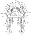
- FIG. 4 is a plan view in which the tail cover 30 is mounted in FIG.
- the tail cover 30 is connected to two branches of a U-shaped cover rear portion 58 that covers the rear end portion of the vehicle body frame FR and opens forward, and a pair of left and right cover sides that extend in the front-rear direction. Parts 60 and 60.
- the tail cover 30 has a crossed hidden line.
- the cover rear portion 58 and the cover side portions 60 and 60 are resin molded products, and are connected by bolts 62 shown in FIG. Specifically, each of the cover side portions 60 and 60 is connected to the cover rear portion 58 at two positions aligned in the front-rear direction.
- the cover rear portion 58 covers the upper part of the rear end portion of the rear frame 2, and the cover side portion 60 covers the outer side of the rear frame 2 and the supported portion 32 of the tandem grip 22. That is, the grip part 34, the pannier attachment part 36, and the rope hook 40 in the tandem grip 22 are exposed to the outside from the tail cover 30.
- the cover rear portion 58 of the tail cover 30 in FIG. 4 has a rear mounting piece 64 protruding forward from the front edge of the base end portion.
- Two rear attachment pieces 64 are provided side by side in the left-right direction, and each rear attachment piece 64 is formed with a bolt insertion hole 64a facing in the up-down direction.
- An intermediate portion mounting piece 66 that protrudes toward the inside of the vehicle body is formed in the front-rear direction intermediate portion of each cover side portion 60, and a bolt insertion hole 66 a that faces in the vertical direction is formed in the intermediate portion mounting piece 66.
- a bolt insertion hole 68 facing in the left-right direction is formed at the front end portion of each cover side portion 60.
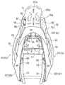
- FIG. 5 shows a state in which the case stay 70 is attached to the plan view of FIG.
- a pair of case stays 70 are provided on the left and right, and both case stays 70, 70 are symmetrical.
- the left and right case stays 70 and 70 are attached to the case attaching portions 38 and 38 of the left and right tandem grips 22, respectively.
- the case stay 70 is a long aluminum member extending in the front-rear direction, and includes a vehicle body mounting portion 76 that constitutes a front half portion and a case support portion 78 that constitutes a rear half portion.
- the vehicle body mounting portion 76 of the case stay 70 is formed with a bolt insertion hole 76a facing in the left-right direction.
- the bolt insertion hole 76a is provided at a position corresponding to the screw hole 38a of the boss (case attachment portion) 38 in FIG. 2, and two bolt insertion holes 76a are provided side by side in the front-rear direction.
- the case support portion 78 of the case stay 70 is formed with a screw hole 78 a that faces in the vertical direction.
- Two screw holes 78a are provided side by side in the front-rear direction.
- a pedestal 74 made of sheet metal is disposed on the upper surface of the case support portion 78 of the case stay 70.
- the pedestal 74 is supported by the left and right case support portions 78 on the left and right sides.
- Bolt insertion holes 81 are formed on the left and right sides of the pedestal 74.
- the bolt insertion holes 81 are formed at positions corresponding to the screw holes 78a of the case support portion 78, and two bolt insertion holes 81 are provided side by side in the front-rear direction.
- the pedestal 74 is connected to the case support portion 78 by a bolt 80 inserted into the bolt insertion hole 81 and screwed into the screw hole 78a.
- a slit 80a extending in the front-rear direction is formed in the middle portion of the base 74 in the left-right direction. Two slits 80a are formed side by side in the front-rear direction.
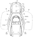
- FIG. 6 which is a plan view shows a state in which the support plate 72 is attached to the pedestal 74 of FIG.
- the support plate 72 is made of resin and is a substantially rectangular plate member in plan view.
- the support plate 72 is disposed on the pedestal 74 and is supported by the case stay 70 via the pedestal 74.
- a through-hole 72 a that faces in the vertical direction is formed in the middle portion of the support plate 72 in the left-right direction.
- the through holes 72a are formed at positions corresponding to the slits 80a of the pedestal 74, and two are provided side by side in the front-rear direction.
- First engagement portions 82, 82 that are engaged with the front portion of the top case 28 (FIG. 1) are formed on the left and right sides of the front portion of the upper surface of the support plate 72.
- a second engaging portion 84 with which the rear portion of the top case 28 (FIG. 1) is engaged is formed in the middle portion in the direction.
- each first engagement portion 82 includes an engagement protrusion that protrudes upward, and the second engagement portion 84 has an engagement hole 84 a that faces obliquely upward to the front.
- the top case 28 of FIG. 1 is engaged with and supported by the support plate 72 via first and second engaging portions 82 and 84 having a known shape.
- tandem grip unit 24 is attached to the rear frame 2.
- a first boss 86 is provided in front of the intermediate cross member 2c in the rear frame 2, and a second boss 88 in the vicinity of the front of the rear end cross member 2b in the rear frame 2.
- the first supported portion 48 of the tandem grip unit 24 is overlapped with the first boss 86
- the second supported portion 50 is overlapped with the second boss 88.
- the bolt 54 shown in FIG. 3 is inserted from above into the through hole 48 a of the first supported portion 48 and tightened into a screw hole (not shown) provided in the first boss 86.
- the bolt 54 is inserted from above into the through hole 50 a of the second supported portion 50 and tightened into a screw hole (not shown) provided in the second boss 88.
- a bolt 56 is inserted into the bolt insertion hole 52 a of the third supported portion (boss) 52 from the outside of the vehicle body (left and right direction), and a screw hole (not shown) of the third boss 90 provided in the rear frame 2. Tighten to.
- the third boss 90 is provided on the outer side of the intermediate cross member 2 c in the rear frame 2. As described above, the tandem grip unit 24 is supported by the rear frame 2.
- the tail cover 30 of FIG. 4 is attached to the rear frame 2. Specifically, the tail cover 30 is inserted from the rear, and the rear attachment piece 64 of the tail cover 30 is overlapped with the attachment piece 94 (FIG. 3) provided on the rear end cross member 2 b of the rear end of the rear frame 2. In this state, the bolt 96 is inserted from above into the bolt insertion hole 64a of the rear mounting piece 64 and screwed into a screw hole 94a (FIG. 3) provided in the mounting piece 94 of the rear frame 2.
- the intermediate attachment piece 66 of the tail cover 30 is overlapped with the attachment protrusion 98 (FIG. 2) provided on the rear frame 2.
- the bolt 100 is inserted from above into the bolt insertion hole 66a of the intermediate mounting piece 66 and tightened into the screw hole 98a (FIG. 2) provided in the mounting projection 98 of the rear frame 2.
- the bolt 104 is inserted into the bolt insertion hole 68 at the front end of the tail cover 30 from the outside of the vehicle body and tightened into a screw hole (not shown) provided in the mounting bracket 102 of the rear frame 2.
- the tail cover 30 is supported by the rear frame 2.
- the case stay 70 and the base 74 shown in FIG. 5 are attached to the boss (case attachment portion) 38 of the tandem grip unit 24.
- the bolt 106 of FIG. 7 is inserted from the inside of the vehicle body into the bolt insertion hole 76a of the case stay 70 and tightened to the screw hole 38a of the boss 38.
- the case stay 70 is attached to the tandem grip unit 24.
- the pedestal 74 is overlaid on the upper surface of the case support portion 78 of the case stay 70 of FIG. 5, and the bolt 80 is inserted from above into the bolt insertion hole 81 of the pedestal 74 and tightened into the screw hole 78 a of the case stay 70. Thereby, the base 74 is attached to the case stay 70.
- the support plate 72 of FIG. Specifically, with the support plate 72 superimposed on the upper surface of the pedestal 74, the bolts 108 shown in FIG. 7 are viewed from above through the through holes 72a of the support plate 72 and the slits 80a of the pedestal 74 (FIG. 5). Insert in order and tighten with a nut (not shown). As a result, the support plate 72 is attached to the case stay 70 via the pedestal 74.
- the panya 26 and the top case 28 of FIG. 1 are attached to the tandem grip unit 24.
- a recess (not shown) formed in the front part of the lower part of the top case 28 is engaged with the first engagement part 82 of the support plate 72 shown in FIG. 7 from the rear.
- a convex portion (not shown) formed at the rear portion of the lower portion of the top case 28 is engaged with the second engagement portion 84 of the support plate 72.
- the top case 28 of FIG. 1 is attached to the support plate 72 and supported by the rear frame 2 via the tandem grip unit 24.
- an engagement protrusion (not shown) provided on the upper portion of the pannier 26 is supported on the recess (panya mounting portion) 36 of the tandem grip unit 24 in FIG.
- the provided engagement recess (not shown) is supported by the step stay 20.
- the panya 26 is supported by the rear frame 2 via the tandem grip unit 24.
- the structure of the engagement protrusion and engagement recess of the panya 26 is known.
- each of the left and right tandem grips 22 shown in FIG. 2 includes a supported portion 32 supported by the rear frame 2, a grip portion 34 held by the passenger, and a pannier mounting portion to which the panya 26 is mounted. 36 and a case attachment portion 38 to which the top case 28 is attached. Therefore, the panya 26 and the top case 28 can be attached without complicating the structure of the rear frame 2. Further, by forming the supported portion 32, the grip portion 34, the pannier attachment portion 36, and the case attachment portion 38 integrally, the number of parts can be reduced and the tandem grip unit 24 can be increased in size and rigidity can be improved. . As a result, the pannier 26 and the top case 28 can be stably supported.
- the rope hook 40 for locking the loading rope is also integrally formed by molding. Therefore, the number of parts can be further reduced, and the large tandem grip unit 24 can stably support the luggage 112 placed on the loader 110 and the passenger seat 14 shown in FIG.
- the supported portion 32 has first and second supported portions 48 and 50 that are fixed by bolts 54 from the vertical direction, and a third supported portion 52 that is fixed by bolts 56 from the left and right directions. Therefore, it can be applied to many types of motorcycles.
- the grip portion 34 and the pannier attachment portion 36 in the tandem grip unit 24 are exposed to the outside from the tail cover 30, and other portions are covered with the tail cover 30 from the outside. Thereby, the supported part 32 of the tandem grip unit 24 can be hidden. As a result, the appearance of the rear portion of the motorcycle is improved and the supported portion 32 does not become a design portion that can be seen from the outside, so that the manufacturing cost of the tandem grip unit 24 can be reduced.
- the present invention is not limited to the above embodiment, and various additions, changes, or deletions are possible without departing from the gist of the present invention.
- the rope hook 40 is integrally formed with the tandem grip unit 24.
- the rope hook 40 may be formed separately and attached to the tandem grip unit 24 or the rear frame 2 by fastening means. Good. Therefore, such a thing is also included in the scope of the present invention.
- Tail cover 32 Supported part 34
- Rope hook 42 Base 44
- First supported part (first attachment piece) 50
- Second supported portion (second mounting piece) 52
- Third supported part (boss) 70
- Case stay 72 Support plate FR Body frame
Landscapes
- Engineering & Computer Science (AREA)
- Mechanical Engineering (AREA)
- Motorcycle And Bicycle Frame (AREA)
- Automatic Cycles, And Cycles In General (AREA)
Abstract
自動二輪車の車体フレームの後部構造を複雑化することなく、パニヤやトップケースを取り付けることができるタンデムグリップ・ユニットを提供する。 タンデムグリップ・ユニット(24)は、左右一対のタンデムグリップ(22)を備えている。各タンデムグリップ(22)は、車体フレーム(FR)に支持される被支持部(32)と、同乗者が把持するグリップ部(34)と、パニヤ(26)が取り付けられるパニヤ取付部(36)と、トップケース(28)が取り付けられるケース取付部(38)とが一体に形成されている型成形品である。
Description
この出願は、2014年3月31日出願の特願2014-071997の優先権を主張するものであり、その全体を参照により本願の一部をなすものとして引用する。
本発明は、車体後部の左右両側に物品収納用のパニヤが着脱可能に取り付けられ、且つ、車体後部の上部に物品収納用のトップケースが着脱可能に取り付けられる自動二輪車に装着されて、同乗者が把持する左右一対のタンデムグリップを含むタンデムグリップ・ユニットに関するものである。
自動二輪車の後部の同乗者シートの下方に、同乗者が把持する左右一対のタンデムグリップを設けたものがある。タンデムグリップは、一般に、車体フレームの後部に支持される(例えば、特許文献1)。
一方、車体後部の左右両側に着脱可能に取り付けられた物品収納用のパニヤや、車体後部の上部に着脱可能に取り付けられた物品収納用のトップケースを備えた自動二輪車では、このようなパニヤやトップケースも車体フレームの後部に支持される。そのため車体フレームの後部の構造が複雑化する。
本発明は、自動二輪車の車体フレームの後部構造を複雑化することなく、パニヤやトップケースを取り付けることができるタンデムグリップ・ユニットを提供することを目的とする。
上記目的を達成するために、本発明のタンデムグリップ・ユニットは、車体後部の左右両側に物品収納用のパニヤが着脱可能に取り付けられ、且つ、車体後部の上部に物品収納用のトップケースが着脱可能に取り付けられる自動二輪車における、同乗者が把持する左右一対のタンデムグリップを含むタンデムグリップ・ユニットであって、各タンデムグリップが、車体フレームに支持される被支持部と、同乗者が把持するグリップ部と、前記パニヤが取り付けられるパニヤ取付部と、前記トップケースが取り付けられるケース取付部とが一体に形成されている型成形品である。
上記構成によれば、左右のタンデムグリップの各々が、車体フレームに支持される被支持部と、同乗者が把持するグリップ部と、パニヤが取り付けられるパニヤ取付部と、トップケースが取り付けられるケース取付部とが一体に形成されているので、車体フレームの後部構造を複雑化することなく、パニヤやトップケースを取り付けることができる。また、被支持部、グリップ部、パニヤ取付部およびケース取付部を一体に形成することで、部品点数を低減できるうえに、タンデムグリップ・ユニットが大形化して剛性が向上する。その結果、パニヤおよびトップケースを安定して支持できる。
本発明において、さらに、荷掛けロープを係止するロープフックが一体に形成されていることが好ましい。この構成によれば、ロープフックも型成形により一体に形成されているので、さらに部品点数を削減できる。また、大形のタンデムグリップ・ユニットにより荷掛け具および荷物を安定して支持できる。
本発明において、前記ケース取付部は、前記タンデムグリップの後端部に設けられたボスからなり、前後方向に延びて前記トップケースを支持する長尺状のケースステーが、前記ボスに着脱自在に取り付けられていることが好ましい。この構成によれば、ケース取付部の小形化が達成できるうえに、トップケースを搭載しない場合、ケースステーを取り外すことで、車体後部の見栄えもよくなる。
本発明において、各タンデムグリップは、前後方向に長手方向を有する長尺形状の基部と、前記基部の上方に配置された前後方向に長い上部と、前記基部の前後端部から上方に延びて前記基部の前後端部と前記上部の前後端部とを連結する前後方向に離間した一対の連結部とを備え、前記基部の車体内側を向く面に前記被支持部が形成され、前記基部の車体外側を向く面に、前記パニヤ取付部が形成され、前記上部における前記各連結部の間の部分が前記グリップ部を形成し、前記上部の後端部に前記ケース取付部が形成されていることが好ましい。この構成によれば、グリップ部の下方で一対の連結部の間に空間を形成することができる。この空間により、同乗者がグリップ部を把持し易くなるとともに、タンデムグリップ・ユニットが軽量化される。
前記基部に被支持部が形成される場合、前記被支持部は、前記基部の車体内側を向く面の前端部および後端部に設けられた第1および第2の被支持部分と、前記基部の前後方向中間部に設けられた第3の被支持部分とを有し、前記第1および第2の被支持部分は上下方向からボルトにより固定され、前記第3の被支持部分は左右方向からボルトにより固定されていることが好ましい。この構成によれば、タンデムグリップ・ユニットの車体フレームへの取付方向を左右方向および上下方向とすることで、多機種の自動二輪車に適用可能となる。
前記被支持部が第1~第3の被支持部分を有する場合、前記車体フレームは、前半部を構成するメインフレームと、後半部を構成するリヤフレームとを有し、前記リヤフレームは、左右一対のリヤフレーム片と、一対の前記リヤフレームの後端部を連結する後端クロスメンバと、その前方で一対の前記リヤフレームを連結する中間クロスメンバとを有し、前記リヤフレームにおける前記中間クロスメンバの前方に、前記第1の被支持部分を支持する第1ボスが設けられ、前記リヤフレームにおける前記後端クロスメンバの近傍に、前記第2の被支持部分を支持する第2ボスが設けられ、前記リヤフレームにおける前記中間クロスメンバの外側方に、前記第3の被支持部分を支持する第3ボスが設けられていることが好ましい。
この構成によれば、第2ボスが後端クロスメンバの近傍に設けられ、且つ、第3ボスが中間クロスメンバの外側方に設けられているから、これら第2および第3ボスの剛性が向上するので、第2および第3の被支持部分の支持が安定する。
本発明に係る自動二輪車は、本発明のタンデムグリップ・ユニットと、前記車体フレームの後端部に着脱自在に取り付けられて、前記車体フレームを外側方から覆うテールカバーとを備え、各タンデムグリップにおける前記グリップ部と前記パニヤ取付部とが、前記テールカバーから外部に露出し、それ以外の部分が前記テールカバーに外側方から覆われている。
この構成によれば、テールカバーにより、タンデムグリップ・ユニットの一部、例えば被支持部を隠すことができる。これにより、車体後部の外観が向上するうえに、被支持部が、露出する意匠部分とならないので、タンデムグリップ・ユニットの製造コストを低減できる。また、テールカバーは着脱自在であるので、被支持部を意匠部品として形成し、テールカバーを取り外すモデルとすることも可能となる。これにより、設計の自由度が向上する。
本発明に係る他の自動二輪車は、本発明のタンデムグリップ・ユニットと、各タンデムグリップに取り付けられた前記パニヤと、一対の前記ケース取付部に取り付けられたケースステーと、一対の前記ケースステーの間に取り付けられた支持プレートと前記支持プレートに支持された前記トップケースとを備えている。これにより、自動二輪車の車体フレームの後部構造を複雑化することなく、パニヤやトップケースを取り付けることができる。
請求の範囲および/または明細書および/または図面に開示された少なくとも2つの構成のどのような組合せも、本発明に含まれる。特に、請求の範囲の各請求項の2つ以上のどのような組合せも、本発明に含まれる。
本発明は、添付の図面を参考にした以下の好適な実施形態の説明からより明瞭に理解されるであろう。しかしながら、実施形態および図面は単なる図示および説明のためのものであり、本発明の範囲を定めるために利用されるべきものではない。本発明の範囲は添付の請求の範囲によって定まる。添付図面において、複数の図面における同一の部品番号は、同一または相当部分を示す。
本発明の一実施形態に係るタンデムグリップ・ユニットを備えた自動二輪車の後部を示す側面図である。
同タンデムグリップ・ユニットを車体フレームに取り付けた状態を示す斜視図である。
図2の平面図である。
図3の平面図にテールカバーを取り付けた平面図である。
図4の平面図にケースステーを取り付けた平面図である。
図5の平面図に支持プレートを取り付けた平面図である。
同自動二輪車の後部を示す斜視図である。
以下、本発明の好ましい実施形態について図面を参照しながら説明する。この明細書中の左右方向は、自動二輪車に乗車したライダーから見た左右を言う。図1は本発明の一実施形態に係るタンデムグリップ・ユニットを備えた自動二輪車の後部の側面図である。この自動二輪車の車体フレームFRは、前半部を構成するメインフレーム1と、メインフレーム1の後部に連結されて車体フレームFRの後半部を構成するリヤフレーム2とを有している。メインフレーム1の前端部に図示しないフロントフォークを介して前輪が支持されている。
メインフレーム1の後端下部には、スイングアームブラケット4が設けられ、このスイングアームブラケット4に、前端部のピポット軸6を介してスイングアーム8が上下揺動自在に支持されている。スイングアーム8の後端部には、後輪10が支持されている。メインフレーム1の中央下部にはエンジンEが支持されており、このエンジンEにより後輪10が駆動される。エンジンEは例えば並列多気筒4サイクルエンジンである。
前記リヤフレーム2にライダー用シート12と同乗者用シート14とが支持されている。ライダー用シート14の下方に、メインフレーム1とスイングアーム8との間に連結されたほぼ前後方向向きの1本の後輪懸架装置16が配置されている。リヤフレーム2におけるライダー用シート12の下方には、ライダーの足乗せである第1フットステップ18が配置され、その後方には、同乗者用の足乗せである第2フットステップ19を支持するステップステー20が取り付けられている。両フットステップ18,19およびステップステー20は左右一対設けられている。
リヤフレーム2における同乗者用シート14の下方には、同乗者が把持する左右一対のタンデムグリップ22を含むタンデムグリップ・ユニット24が取り付けられている。車体後部の左右両側に物品収納用のパニヤ26が配置され、タンデムグリップ・ユニット24を介してリヤフレーム2に着脱可能に取り付けられている。車体後端の上部に物品収納用のトップケース28が配置され、タンデムグリップ・ユニット24を介してリヤフレーム2に着脱可能に取り付けられている。トップケース28は、後述のケースステー70および支持プレート72を介してタンデムグリップ・ユニット24に取り付けられている。さらに、リヤフレーム2の後端部に、リヤフレーム2を外側方から覆う樹脂製のテールカバー30が支持されている。
図2は、リヤフレーム2に取り付けたタンデムグリップ・ユニット24を前方斜め上方から見た斜視図で、図3はその平面図である。リヤフレーム2は、左右一対のリヤフレーム片2aの後端部に、両リヤフレーム片2a,2aを連結する後端クロスメンバ2bが接合され、さらに、その前方部に、両リヤフレーム片2a,2aを連結する中間クロスメンバ2cが接合されている。タンデムグリップ・ユニット24の左右のタンデムグリップ22,22は左右対称形状である。本実施形態では、各タンデムグリップ22は、アルミダイキャスト製である。
図2に示すように、各タンデムグリップ22は、リヤフレーム2に支持される被支持部32と、同乗者が把持するグリップ部34と、パニヤ26(図1)が取り付けられるパニヤ取付部36と、トップケース28(図1)が取り付けられるケース取付部38と、荷掛けロープを係止するロープフック40が一体に形成された型成形品である。
詳細には、各タンデムグリップ22は、前後方向に長手方向を有する長尺形状の基部42と、基部42の上方に配置された前後方向に長い上部44と、基部42の前後端部から上方に延びて基部42の前後端部と上部44の前後端部とを連結する前後方向に離間した一対の連結部46とを有している。つまり、タンデムグリップ22には、基部42、上部44および前後の連結部46,46で囲まれた、左右方向に貫通する前後方向に長い空間69が形成されている。
基部42の車体内側を向く面に前記被支持部32が形成されている。被支持部32は、基部42の車体内側を向く面の前端部および後端部に設けられた第1および第2の被支持部分48,50と、基部42の前後方向中間部に設けられた第3の被支持部分52とを有している。第1および第2の被支持部分48,50は上下方向からボルト54により固定され、第3の被支持部分52は左右方向からボルト56により固定されている。
詳細には、第1の被支持部分48は、図3に示すように、基部42の車体内側を向く面の前端部から車体内側に突出する第1取付片48からなり、この第1取付片48に上方を向く貫通孔48aが形成されている。第2の被支持部分50は、基部42の車体内側を向く面の後端部から車体内側に突出する第2取付片50からなり、この第2取付片50に上方を向く貫通孔50aが形成されている。第3の被支持部分52は、基部42の前後方向中間部に設けたボスからなり、このボス52に左右方向を向いたボルト挿通孔52aが形成されている。第3の被支持部分52は、基部42の車体内側を向く面に設けられて内側へ突出している。
図2に示すように、基部42の車体外側を向く面に、前記パニヤ取付部36が形成されている。パニヤ取付部36は、基部42の車体外側を向く面の前端部および後端部に設けられ、車体内側へ凹入した有底の凹所からなる。パニヤ取付部36は、パニヤ26(図1)の被取付部の構造に合わせて構成されるもので、本実施形態の構造に限定されない。
タンデムグリップ22の上部44における前後の連結部46,46の間の部分が前記グリップ部34を構成している。上部44の後端部に、前記ケース取付部38が形成されている。ケース取付部38は、上部44の後端部の内側面から車体内側に延びるボス38からなり、本実施形態では、前後方向に並んで2つ設けられている。各ボス38に、車体内側を向くねじ孔38aが形成されている。ロープフック40は、基部42の前端部と後端部に設けられ、基部42の下面から下方に突出する突状体40からなる。
図4は、図3に前記テールカバー30を装着した平面図である。テールカバー30は、車体フレームFRの後端部を覆い前方に開いたU字形のカバー後部58と、U字形のカバー後部58の2つの枝部に連結されて前後方向に延びる左右一対のカバー側部60,60とを有している。明瞭化のために、テールカバー30にはクロスした陰線が付されている。カバー後部58と各カバー側部60,60は、樹脂の型成形品であり、図7に示すボルト62により連結されている。詳細には、各カバー側部60,60は、前後方向に並んだ2か所でカバー後部58に連結されている。
カバー後部58はリヤフレーム2の後端部の上方を覆い、カバー側部60はリヤフレーム2およびタンデムグリップ22の被支持部32の外側方を覆っている。つまり、タンデムグリップ22におけるグリップ部34、パニヤ取付部36およびロープフック40が、テールカバー30から外部に露出している。
図4のテールカバー30のカバー後部58は、その基端部の前縁から前方に突出する後部取付片64を有している。後部取付片64は左右方向に並んで2つ設けられ、各後部取付片64に上下方向を向くボルト挿通孔64aが形成されている。各カバー側部60における前後方向中間部に、車体内側に突出する中間部取付片66が形成され、この中間部取付片66に上下方向を向くボルト挿通孔66aが形成されている。さらに、各カバー側部60の前端部に、左右方向を向くボルト挿通孔68が形成されている。
図5は、図4の平面図に前記ケースステー70を取り付けた状態を示す。図5に示すように、ケースステー70は左右一対設けられており、両ケースステー70,70は左右対称形状である。左右のケースステー70,70は、左右のタンデムグリップ22のケース取付部38,38にそれぞれ取り付けられる。ケースステー70は、前後方向に延びるアルミニウム製の長尺状部材であり、前半部を構成する車体取付部76と、後半部を構成するケース支持部78とを有している。
図7に示すように、ケースステー70の車体取付部76は、左右方向を向いたボルト挿通孔76aが形成されている。ボルト挿通孔76aは、図2のボス(ケース取付部)38のねじ孔38aに対応した位置に設けられ、前後方向に並んで2つ設けられている。
図5に示すように、ケースステー70のケース支持部78は、上下方向を向くねじ孔78aが形成されている。ねじ孔78aは、前後方向に並んで2つ設けられている。ケースステー70のケース支持部78の上面に、板金からなる台座74が配置されている。
台座74は、左右両側部で左右のケース支持部78に支持される。台座74における左右両側部にボルト挿通孔81が形成されている。ボルト挿通孔81は、ケース支持部78のねじ孔78aに対応する位置に形成され、前後方向に並んで2つ設けられている。台座74はボルト挿通孔81に挿通されねじ孔78aにねじ込んだボルト80によりケース支持部78に連結されている。台座74における左右方向の中間部には、前後方向に延びるスリット80aが形成されている。スリット80aは、前後方向に並んで2つ形成されている。
平面図である図6は、図5の台座74に前記支持プレート72を取り付けた状態を示す。支持プレート72は、樹脂製で、平面視でほぼ矩形の板状部材である。支持プレート72は、台座74の上に配置され、台座74を介してケースステー70に支持されている。
図6に示すように、支持プレート72の左右方向の中間部に、上下方向を向く貫通孔72aが形成されている。貫通孔72aは、台座74のスリット80aに対応した位置に形成され、前後方向に並んで2つ設けられている。支持プレート72の上面の前部における左右両側部に、トップケース28(図1)の前部が係合される第1係合部82,82が形成され、支持プレート72の上面の後部における左右方向中間部に、トップケース28(図1)の後部が係合される第2係合部84が形成されている。
図7に示すように、各第1係合部82は、上方に突出した係合突起からなり、第2係合部84は前方斜め上方を向いた係合孔84aを有している。公知の形状である第1および第2係合部82,84を介して、図1のトップケース28が支持プレート72に係合して支持される。
つぎに、図1のタンデムグリップ・ユニット24、パニヤ26、トップケース28およびテールカバー30のリヤフレーム2への取付方法を説明する。まず、リヤフレーム2にタンデムグリップ・ユニット24を取り付ける。
具体的には、図2に示すように、リヤフレーム2における中間クロスメンバ2cの前方に第1ボス86が設けられ、且つ、リヤフレーム2における後端クロスメンバ2bの前方近傍に第2ボス88が設けられている。第1ボス86に、タンデムグリップ・ユニット24の第1の被支持部分48を重ね、第2ボス88に第2の被支持部分50を重ねる。この状態で、図3に示すボルト54を上方から第1の被支持部分48の貫通孔48aに挿通し、第1ボス86に設けられたねじ孔(図示せず)に締め付ける。同様に、ボルト54を上方から第2の被支持部分50の貫通孔50aに挿通し、第2ボス88に設けられたねじ孔(図示せず)に締め付ける。
さらに、第3の被支持部(ボス)52のボルト挿通孔52aに、車体外側(左右方向)からボルト56を挿通し、リヤフレーム2に設けた第3ボス90のねじ孔(図示せず)に締め付ける。第3ボス90は、リヤフレーム2における中間クロスメンバ2cの外側方に設けられている。以上により、タンデムグリップ・ユニット24がリヤフレーム2に支持される。
つぎに、図4のテールカバー30をリヤフレーム2に取り付ける。具体的には、テールカバー30を後方から差し込んで、リヤフレーム2の後端の後端クロスメンバ2bに設けられた取付片94(図3)に、テールカバー30の後部取付片64を重ねる。この状態で、ボルト96を上方から後部取付片64のボルト挿通孔64aに挿通し、リヤフレーム2の取付片94に設けられたねじ孔94a(図3)にねじ込む。
つづいて、リヤフレーム2に設けられた取付突起98(図2)に、テールカバー30の中間部取付片66を重ねる。この状態で、ボルト100を上方から中間部取付片66のボルト挿通孔66aに挿通し、リヤフレーム2の取付突起98に設けたねじ孔98a(図2)に締め付ける。さらに、テールカバー30の前端のボルト挿通孔68に、車体外側からボルト104を挿通し、リヤフレーム2の取付ブラケット102に設けたねじ孔(図示せず)に締め付ける。以上により、テールカバー30がリヤフレーム2に支持される。
つぎに、図5のケースステー70および台座74をタンデムグリップ・ユニット24のボス(ケース取付部)38に取り付ける。具体的には、図7のボルト106を車体内側からケースステー70のボルト挿通孔76aに挿通し、ボス38のねじ孔38aに締め付ける。これにより、ケースステー70がタンデムグリップ・ユニット24に取り付けられる。
つづいて、図5のケースステー70のケース支持部78の上面に台座74を重ね、ボルト80を上方から台座74のボルト挿通孔81に挿通し、ケースステー70のねじ孔78aに締め付ける。これにより、台座74がケースステー70に取り付けられる。
つぎに、図6の支持プレート72を台座74に取り付ける。具体的には、台座74の上面に支持プレート72を重ねた状態で、図7に示すボルト108を上方から、図6の支持プレート72の貫通孔72aおよび台座74のスリット80a(図5)の順に挿通し、図示しないナットで締め付ける。これにより、支持プレート72が台座74を介してケースステー70に取り付けられる。
つづいて、図1のパニヤ26およびトップケース28をタンデムグリップ・ユニット24に取り付ける。トップケース28の下部の前部に形成された凹所(図示せず)を、後方から図7に示す支持プレート72の第1係合部82に係合する。この状態で、トップケース28の下部の後部に形成された凸部(図示せず)を支持プレート72の第2係合部84に係合する。これにより、図1のトップケース28が支持プレート72に取り付けられ、タンデムグリップ・ユニット24を介してリヤフレーム2に支持される。
さらに、パニヤ26の上部に設けられた係合突部(図示せず)を、図7のタンデムグリップ・ユニット24の凹所(パニヤ取付部)36に支持した状態で、パニヤ26の前部に設けられた係合凹部(図示せず)をステップステー20に支持する。これにより、パニヤ26がタンデムグリップ・ユニット24を介してリヤフレーム2に支持される。なお、パニヤ26の係合突部および係合凹部の構造は公知である。
上記構成によれば、図2に示す左右のタンデムグリップ22の各々が、リヤフレーム2に支持される被支持部32と、同乗者が把持するグリップ部34と、パニヤ26が取り付けられるパニヤ取付部36と、トップケース28が取り付けられるケース取付部38とが一体に形成されている型成形品である。したがって、リヤフレーム2の構造を複雑化することなく、パニヤ26やトップケース28を取り付けることができる。また、被支持部32、グリップ部34、パニヤ取付部36およびケース取付部38を一体に形成することで、部品点数を低減できるうえに、タンデムグリップ・ユニット24が大形化して剛性が向上する。その結果、パニヤ26およびトップケース28を安定して支持できる。
さらに、荷掛けロープを係止するロープフック40も型成形により一体に形成されている。したがって、さらに部品点数を削減できるうえに、大形のタンデムグリップ・ユニット24により、図1に示す荷掛け具110および同乗者シート14上に載置した荷物112を安定して支持できる。
また、グリップ部34の下方で一対の連結部46,46の間に空間69が形成されているので、同乗者がグリップ部34を把持し易くなるとともに、タンデムグリップ・ユニット24が軽量化される。
さらに、被支持部32が、上下方向からボルト54により固定される第1および第2の被支持部分48,50と、左右方向からボルト56により固定される第3の被支持部分52とを有しているので、多機種の自動二輪車に適用可能となる。
また、タンデムグリップ・ユニット24におけるグリップ部34とパニヤ取付部36とが、テールカバー30から外部に露出し、それ以外の部分がテールカバー30に外側方から覆われている。これにより、タンデムグリップ・ユニット24の被支持部32を隠すことができる。その結果、自動二輪車の後部の外観が向上するうえに、被支持部32が外部から見える意匠部分とならないので、タンデムグリップ・ユニット24の製造コストを低減できる。
本発明は、以上の実施形態に限定されるものでなく、本発明の要旨を逸脱しない範囲内で、種々の追加、変更または削除が可能である。例えば、上記実施形態では、タンデムグリップ・ユニット24にロープフック40が一体形成されているが、ロープフック40を別体で形成し、締結手段によりタンデムグリップ・ユニット24またはリヤフレーム2に取り付けてもよい。したがって、そのようなものも本発明の範囲内に含まれる。
22 タンデムグリップ
24 タンデムグリップ・ユニット
26 パニヤ
28 トップケース
30 テールカバー
32 被支持部
34 グリップ部
36 パニヤ取付部(凹所)
38 ケース取付部(ボス)
40 ロープフック
42 基部
44 上部
46 連結部
48 第1の被支持部分(第1取付片)
50 第2の被支持部分(第2取付片)
52 第3の被支持部分(ボス)
70 ケースステー
72 支持プレート
FR 車体フレーム
24 タンデムグリップ・ユニット
26 パニヤ
28 トップケース
30 テールカバー
32 被支持部
34 グリップ部
36 パニヤ取付部(凹所)
38 ケース取付部(ボス)
40 ロープフック
42 基部
44 上部
46 連結部
48 第1の被支持部分(第1取付片)
50 第2の被支持部分(第2取付片)
52 第3の被支持部分(ボス)
70 ケースステー
72 支持プレート
FR 車体フレーム
Claims (9)
- 車体後部の左右両側に物品収納用のパニヤが着脱可能に取り付けられ、且つ、車体後部の上部に物品収納用のトップケースが着脱可能に取り付けられる自動二輪車における、同乗者が把持する左右一対のタンデムグリップを含むタンデムグリップ・ユニットであって、
各タンデムグリップが、車体フレームに支持される被支持部と、同乗者が把持するグリップ部と、前記パニヤが取り付けられるパニヤ取付部と、前記トップケースが取り付けられるケース取付部とが一体に形成されている型成形品であるタンデムグリップ・ユニット。 - 請求項1に記載のタンデムグリップ・ユニットにおいて、さらに、荷掛けロープを係止するロープフックが一体に形成されているタンデムグリップ・ユニット。
- 請求項1または2に記載のタンデムグリップ・ユニットにおいて、前記ケース取付部は、前記タンデムグリップの後端部に設けられたボスからなり、
前後方向に延びて前記トップケースを支持する長尺状のケースステーが、前記ボスに着脱自在に取り付けられているタンデムグリップ・ユニット。 - 請求項1から3のいずれか一項に記載のタンデムグリップ・ユニットにおいて、各タンデムグリップは、前後方向に長手方向を有する長尺形状の基部と、
前記基部の上方に配置された前後方向に長い上部と、
前記基部の前後端部から上方に延びて前記基部の前後端部と前記上部の前後端部とを連結する前後方向に離間した一対の連結部と、を備え、
前記基部の車体内側を向く面に、前記被支持部が形成され、
前記基部の車体外側を向く面に、前記パニヤ取付部が形成され、
前記上部における前記各連結部の間の部分が前記グリップ部を形成し、
前記上部の後端部に前記ケース取付部が形成されているタンデムグリップ・ユニット。 - 請求項4に記載のタンデムグリップ・ユニットにおいて、前記被支持部は、前記基部の車体内側を向く面の前端部および後端部に設けられた第1および第2の被支持部分と、前記基部の前後方向中間部に設けられた第3の被支持部分とを有し、
前記第1および第2の被支持部分は上下方向からボルトにより固定され、前記第3の被支持部分は左右方向からボルトにより固定されているタンデムグリップ・ユニット。 - 請求項5に記載のタンデムグリップ・ユニットにおいて、前記車体フレームは、前半部を構成するメインフレームと、後半部を構成するリヤフレームとを有し、
前記リヤフレームは、左右一対のリヤフレーム片と、一対の前記リヤフレームの後端部を連結する後端クロスメンバと、その前方で一対の前記リヤフレームを連結する中間クロスメンバとを有し、
前記リヤフレームにおける前記中間クロスメンバの前方に、前記第1の被支持部分を支持する第1ボスが設けられ、
前記リヤフレームにおける前記後端クロスメンバの近傍に、前記第2の被支持部分を支持する第2ボスが設けられ、
前記リヤフレームにおける前記中間クロスメンバの外側方に、前記第3の被支持部分を支持する第3ボスが設けられているタンデムグリップ・ユニット。 - 請求項1から4のいずれか一項に記載のタンデムグリップ・ユニットと、
前記車体フレームの後端部に着脱自在に取り付けられて、前記車体フレームを外側方から覆うテールカバーと、を備え、
各タンデムグリップにおける前記グリップ部と前記パニヤ取付部とが、前記テールカバーから外部に露出し、それ以外の部分が前記テールカバーに外側方から覆われている自動二輪車。 - 請求項1から6のいずれか一項に記載のタンデムグリップ・ユニットと、
各タンデムグリップに取り付けられた前記パニヤと、
一対の前記ケース取付部に取り付けられたケースステーと、
一対の前記ケースステーの間に取り付けられた支持プレートと、
前記支持プレートに支持された前記トップケースと、を備えた自動二輪車。 - 請求項8に記載の自動二輪車において、前記車体フレームの後端部に着脱自在に取り付けられて、前記車体フレームを外側方から覆うテールカバーを備え、
各タンデムグリップにおける前記グリップ部と前記パニヤ取付部とが、前記テールカバーから外部に露出し、それ以外の部分が前記テールカバーに外側方から覆われている自動二輪車。
Priority Applications (2)
| Application Number | Priority Date | Filing Date | Title |
|---|---|---|---|
| EP15772351.1A EP3127794B1 (en) | 2014-03-31 | 2015-02-04 | Tandem grip unit for motorcycle |
| US15/271,445 US10011313B2 (en) | 2014-03-31 | 2016-09-21 | Tandem grip unit for motorcycle |
Applications Claiming Priority (2)
| Application Number | Priority Date | Filing Date | Title |
|---|---|---|---|
| JP2014-071997 | 2014-03-31 | ||
| JP2014071997A JP6266408B2 (ja) | 2014-03-31 | 2014-03-31 | 自動二輪車のタンデムグリップ・ユニット |
Related Child Applications (1)
| Application Number | Title | Priority Date | Filing Date |
|---|---|---|---|
| US15/271,445 Continuation US10011313B2 (en) | 2014-03-31 | 2016-09-21 | Tandem grip unit for motorcycle |
Publications (1)
| Publication Number | Publication Date |
|---|---|
| WO2015151575A1 true WO2015151575A1 (ja) | 2015-10-08 |
Family
ID=54239916
Family Applications (1)
| Application Number | Title | Priority Date | Filing Date |
|---|---|---|---|
| PCT/JP2015/053053 Ceased WO2015151575A1 (ja) | 2014-03-31 | 2015-02-04 | 自動二輪車のタンデムグリップ・ユニット |
Country Status (4)
| Country | Link |
|---|---|
| US (1) | US10011313B2 (ja) |
| EP (1) | EP3127794B1 (ja) |
| JP (1) | JP6266408B2 (ja) |
| WO (1) | WO2015151575A1 (ja) |
Cited By (3)
| Publication number | Priority date | Publication date | Assignee | Title |
|---|---|---|---|---|
| TWI562924B (ja) * | 2015-11-24 | 2016-12-21 | Kwang Yang Motor Co | |
| US11492058B2 (en) * | 2018-11-28 | 2022-11-08 | Honda Motor Co., Ltd. | Grab rail of saddle riding vehicle |
| JP2023045605A (ja) * | 2021-09-22 | 2023-04-03 | スズキ株式会社 | サイドケース取付構造 |
Families Citing this family (8)
| Publication number | Priority date | Publication date | Assignee | Title |
|---|---|---|---|---|
| JP6750097B2 (ja) * | 2017-03-30 | 2020-09-02 | 本田技研工業株式会社 | 鞍乗り型車両の車体フレーム構造 |
| CN107310666A (zh) * | 2017-07-25 | 2017-11-03 | 力帆实业(集团)股份有限公司 | 摩托车后扶手在车架上的侧方位安装结构 |
| WO2019167220A1 (ja) * | 2018-03-01 | 2019-09-06 | 本田技研工業株式会社 | 鞍乗型車両 |
| JP2021054129A (ja) * | 2019-09-27 | 2021-04-08 | ヤマハ発動機株式会社 | 鞍乗型車両 |
| DE102020121719A1 (de) | 2020-08-19 | 2022-02-24 | Bayerische Motoren Werke Aktiengesellschaft | Sitzvorrichtung für ein Neigefahrzeug |
| DE102020122627A1 (de) * | 2020-08-31 | 2022-03-03 | Bayerische Motoren Werke Aktiengesellschaft | Neigefahrzeug mit Trägervorrichtung |
| DE102022115884A1 (de) * | 2022-06-27 | 2023-12-28 | Bayerische Motoren Werke Aktiengesellschaft | Neigefahrzeug und Verfahren zum Betreiben eines Neigefahrzeugs |
| IT202300010788A1 (it) * | 2023-05-29 | 2024-11-29 | Piaggio & C Spa | Portapacchi di un veicolo a sella cavalcabile |
Citations (4)
| Publication number | Priority date | Publication date | Assignee | Title |
|---|---|---|---|---|
| JPH04123988A (ja) * | 1990-09-17 | 1992-04-23 | Yamaha Motor Co Ltd | 自動二輪車のリヤキャリア |
| JP2006103647A (ja) * | 2004-09-30 | 2006-04-20 | Honda Motor Co Ltd | 自動2輪車のシートレール取付構造 |
| JP2013075552A (ja) * | 2011-09-29 | 2013-04-25 | Honda Motor Co Ltd | 鞍乗り型車両 |
| JP2013248980A (ja) * | 2012-05-31 | 2013-12-12 | Honda Motor Co Ltd | 鞍乗型車両 |
Family Cites Families (13)
| Publication number | Priority date | Publication date | Assignee | Title |
|---|---|---|---|---|
| DE3211308C2 (de) * | 1982-03-26 | 1986-08-28 | Krauser Kraftfahrzeugzubehör Vertriebs-GmbH, 8905 Mering | Das Hinterrad eines Motorrads umgreifende Halterungseinrichtung |
| JPS62122790U (ja) | 1986-01-27 | 1987-08-04 | ||
| EP0709281A1 (en) * | 1994-10-31 | 1996-05-01 | Pedro Lucia Monforte | Adjustable bracket for pannier caseholder for motorcycles and similar vehicles |
| DE19841748A1 (de) * | 1998-09-11 | 2000-03-16 | Bayerische Motoren Werke Ag | Motorrad mit Behältnis seitlich eines Soziussitzes |
| JP4037076B2 (ja) * | 2001-09-11 | 2008-01-23 | 本田技研工業株式会社 | 自動二輪車 |
| JP2007091140A (ja) * | 2005-09-30 | 2007-04-12 | Honda Motor Co Ltd | 鞍乗り型車両の収納部構造 |
| US7793747B2 (en) * | 2007-01-22 | 2010-09-14 | Brown Peter L | Touring motorcycle modification kit |
| WO2010111555A2 (en) * | 2009-03-25 | 2010-09-30 | Legends Motorcycles, Inc. | Displaceable utility positioning system for motorcycles |
| JP2012201238A (ja) * | 2011-03-25 | 2012-10-22 | Suzuki Motor Corp | 鞍乗型車輌 |
| JP5677905B2 (ja) * | 2011-07-12 | 2015-02-25 | 本田技研工業株式会社 | 自動二輪車の荷掛け構造 |
| EP2574348A1 (en) * | 2011-09-28 | 2013-04-03 | FP PROGETTI ITALIA S.r.L. Unipersonale | Disinfecting foil for covering handles, head restraint and cushions' drape |
| JP5872447B2 (ja) * | 2012-12-13 | 2016-03-01 | 本田技研工業株式会社 | 鞍乗り型車両の後部構造 |
| US8985416B2 (en) * | 2013-01-10 | 2015-03-24 | Harley-Davidson Motor Company Group, LLC | Mounting interface for a removable motorcycle accessory |
-
2014
- 2014-03-31 JP JP2014071997A patent/JP6266408B2/ja active Active
-
2015
- 2015-02-04 EP EP15772351.1A patent/EP3127794B1/en active Active
- 2015-02-04 WO PCT/JP2015/053053 patent/WO2015151575A1/ja not_active Ceased
-
2016
- 2016-09-21 US US15/271,445 patent/US10011313B2/en active Active
Patent Citations (4)
| Publication number | Priority date | Publication date | Assignee | Title |
|---|---|---|---|---|
| JPH04123988A (ja) * | 1990-09-17 | 1992-04-23 | Yamaha Motor Co Ltd | 自動二輪車のリヤキャリア |
| JP2006103647A (ja) * | 2004-09-30 | 2006-04-20 | Honda Motor Co Ltd | 自動2輪車のシートレール取付構造 |
| JP2013075552A (ja) * | 2011-09-29 | 2013-04-25 | Honda Motor Co Ltd | 鞍乗り型車両 |
| JP2013248980A (ja) * | 2012-05-31 | 2013-12-12 | Honda Motor Co Ltd | 鞍乗型車両 |
Cited By (4)
| Publication number | Priority date | Publication date | Assignee | Title |
|---|---|---|---|---|
| TWI562924B (ja) * | 2015-11-24 | 2016-12-21 | Kwang Yang Motor Co | |
| US11492058B2 (en) * | 2018-11-28 | 2022-11-08 | Honda Motor Co., Ltd. | Grab rail of saddle riding vehicle |
| JP2023045605A (ja) * | 2021-09-22 | 2023-04-03 | スズキ株式会社 | サイドケース取付構造 |
| JP7735753B2 (ja) | 2021-09-22 | 2025-09-09 | スズキ株式会社 | サイドケース取付構造 |
Also Published As
| Publication number | Publication date |
|---|---|
| US10011313B2 (en) | 2018-07-03 |
| EP3127794A4 (en) | 2018-01-10 |
| JP2015193308A (ja) | 2015-11-05 |
| JP6266408B2 (ja) | 2018-01-24 |
| EP3127794B1 (en) | 2021-04-14 |
| EP3127794A1 (en) | 2017-02-08 |
| US20170008585A1 (en) | 2017-01-12 |
Similar Documents
| Publication | Publication Date | Title |
|---|---|---|
| JP6266408B2 (ja) | 自動二輪車のタンデムグリップ・ユニット | |
| JP5131470B2 (ja) | 自動二輪車 | |
| US9434436B1 (en) | Rear structure for saddle-ride type vehicle | |
| JP6708687B2 (ja) | 自動二輪車のシートフレーム | |
| JP5963206B2 (ja) | 鞍乗り型車両のシート支持構造 | |
| JP5835690B2 (ja) | 鞍乗り型車両 | |
| JP4937058B2 (ja) | 自動二輪車 | |
| JP6134589B2 (ja) | 鞍乗り型車両 | |
| JP2010234906A (ja) | 鞍乗り型車両 | |
| JP6395537B2 (ja) | 自動二輪車のパニア取付構造 | |
| JP6363445B2 (ja) | 自動二輪車の後部構造 | |
| JP6484422B2 (ja) | 車両 | |
| CN205168717U (zh) | 鞍骑型车辆的后载物架 | |
| JP5858369B2 (ja) | 鞍乗り型車両 | |
| JP2014240255A (ja) | 鞍乗り型車両 | |
| JP6129693B2 (ja) | 鞍乗り型車両 | |
| JP6133743B2 (ja) | 鞍乗り型車両 | |
| JP2017132435A (ja) | 鞍乗型車両 | |
| US10597103B2 (en) | Saddle-type vehicle | |
| JP2016037116A (ja) | 収納ボックス | |
| JP7018417B2 (ja) | 鞍乗型車両 | |
| JP2002104265A (ja) | スクータ型自動二輪車 | |
| JP6625411B2 (ja) | 鞍乗型車両のリアフレーム構造 | |
| JP6492448B2 (ja) | 自動二輪車の収納ボックスの補強構造 | |
| JP5851296B2 (ja) | 鞍乗り型車両のグラブレール取付構造 |
Legal Events
| Date | Code | Title | Description |
|---|---|---|---|
| 121 | Ep: the epo has been informed by wipo that ep was designated in this application |
Ref document number: 15772351 Country of ref document: EP Kind code of ref document: A1 |
|
| NENP | Non-entry into the national phase |
Ref country code: DE |
|
| REEP | Request for entry into the european phase |
Ref document number: 2015772351 Country of ref document: EP |
|
| WWE | Wipo information: entry into national phase |
Ref document number: 2015772351 Country of ref document: EP |