WO2015159609A1 - 荷重式扉開閉装置 - Google Patents
荷重式扉開閉装置 Download PDFInfo
- Publication number
- WO2015159609A1 WO2015159609A1 PCT/JP2015/056822 JP2015056822W WO2015159609A1 WO 2015159609 A1 WO2015159609 A1 WO 2015159609A1 JP 2015056822 W JP2015056822 W JP 2015056822W WO 2015159609 A1 WO2015159609 A1 WO 2015159609A1
- Authority
- WO
- WIPO (PCT)
- Prior art keywords
- door
- opening
- arm
- door opening
- sliding member
- Prior art date
- Legal status (The legal status is an assumption and is not a legal conclusion. Google has not performed a legal analysis and makes no representation as to the accuracy of the status listed.)
- Ceased
Links
Images



Classifications
-
- E—FIXED CONSTRUCTIONS
- E05—LOCKS; KEYS; WINDOW OR DOOR FITTINGS; SAFES
- E05F—DEVICES FOR MOVING WINGS INTO OPEN OR CLOSED POSITION; CHECKS FOR WINGS; WING FITTINGS NOT OTHERWISE PROVIDED FOR, CONCERNED WITH THE FUNCTIONING OF THE WING
- E05F13/00—Mechanisms operated by the movement or weight of a person or vehicle
- E05F13/04—Mechanisms operated by the movement or weight of a person or vehicle by platforms lowered by the weight of the user
-
- E—FIXED CONSTRUCTIONS
- E05—LOCKS; KEYS; WINDOW OR DOOR FITTINGS; SAFES
- E05D—HINGES OR SUSPENSION DEVICES FOR DOORS, WINDOWS OR WINGS
- E05D15/00—Suspension arrangements for wings
- E05D15/06—Suspension arrangements for wings for wings sliding horizontally more or less in their own plane
-
- E—FIXED CONSTRUCTIONS
- E05—LOCKS; KEYS; WINDOW OR DOOR FITTINGS; SAFES
- E05F—DEVICES FOR MOVING WINGS INTO OPEN OR CLOSED POSITION; CHECKS FOR WINGS; WING FITTINGS NOT OTHERWISE PROVIDED FOR, CONCERNED WITH THE FUNCTIONING OF THE WING
- E05F1/00—Closers or openers for wings, not otherwise provided for in this subclass
- E05F1/02—Closers or openers for wings, not otherwise provided for in this subclass gravity-actuated, e.g. by use of counterweights
- E05F1/025—Closers or openers for wings, not otherwise provided for in this subclass gravity-actuated, e.g. by use of counterweights with rectilinearly-moving counterweights
-
- E—FIXED CONSTRUCTIONS
- E06—DOORS, WINDOWS, SHUTTERS, OR ROLLER BLINDS IN GENERAL; LADDERS
- E06B—FIXED OR MOVABLE CLOSURES FOR OPENINGS IN BUILDINGS, VEHICLES, FENCES OR LIKE ENCLOSURES IN GENERAL, e.g. DOORS, WINDOWS, BLINDS, GATES
- E06B3/00—Window sashes, door leaves, or like elements for closing wall or like openings; Layout of fixed or moving closures, e.g. windows in wall or like openings; Features of rigidly-mounted outer frames relating to the mounting of wing frames
- E06B3/32—Arrangements of wings characterised by the manner of movement; Arrangements of movable wings in openings; Features of wings or frames relating solely to the manner of movement of the wing
- E06B3/34—Arrangements of wings characterised by the manner of movement; Arrangements of movable wings in openings; Features of wings or frames relating solely to the manner of movement of the wing with only one kind of movement
- E06B3/42—Sliding wings; Details of frames with respect to guiding
- E06B3/46—Horizontally-sliding wings
- E06B3/4636—Horizontally-sliding wings for doors
-
- E—FIXED CONSTRUCTIONS
- E05—LOCKS; KEYS; WINDOW OR DOOR FITTINGS; SAFES
- E05D—HINGES OR SUSPENSION DEVICES FOR DOORS, WINDOWS OR WINGS
- E05D15/00—Suspension arrangements for wings
- E05D15/06—Suspension arrangements for wings for wings sliding horizontally more or less in their own plane
- E05D15/0621—Details, e.g. suspension or supporting guides
- E05D15/0626—Details, e.g. suspension or supporting guides for wings suspended at the top
- E05D15/063—Details, e.g. suspension or supporting guides for wings suspended at the top on wheels with fixed axis
-
- E—FIXED CONSTRUCTIONS
- E05—LOCKS; KEYS; WINDOW OR DOOR FITTINGS; SAFES
- E05F—DEVICES FOR MOVING WINGS INTO OPEN OR CLOSED POSITION; CHECKS FOR WINGS; WING FITTINGS NOT OTHERWISE PROVIDED FOR, CONCERNED WITH THE FUNCTIONING OF THE WING
- E05F1/00—Closers or openers for wings, not otherwise provided for in this subclass
- E05F1/08—Closers or openers for wings, not otherwise provided for in this subclass spring-actuated, e.g. for horizontally sliding wings
- E05F1/16—Closers or openers for wings, not otherwise provided for in this subclass spring-actuated, e.g. for horizontally sliding wings for sliding wings
Definitions
- the present invention relates to a load-type door opening and closing device provided with an opening and closing mechanism that opens and closes a door using the weight of a person.
- the present invention relates to an automatic door opening method that opens a sliding door of an entrance by multiplying the weight of a user or the weight of a cart, and an automatic door opening and closing using the method. It belongs to the technical field of doorway door mechanisms that do not have a power source such as electric motors and hydraulic motors and operate only with the stepping force of the user or cart, and in particular, no power source natural energy with stepping force operation that moves the door in the opening direction It relates to doors with automatic opening and closing.
- Such a load-type door opening and closing device includes a sliding support rail that tilts downward in the closing direction of the door to support the door, a door opening rail that tilts downward in the door opening direction and is fixed to the door, and a door opening rail.
- a sliding member that is slidably contacted with the sliding member, and a door opening mechanism that converts a downward treading force applied to the tread plate into an upward component force of the sliding member via a lever.
- Patent Document 1 a transmission mechanism that converts the amount of subsidence of the treads provided on the floor surface at the front and rear positions of the sliding door to a predetermined displacement via a lever is transmitted, and the subsidence due to the weight of the transmission mechanism and the adjustment weight is The weight balance is set so as to keep the tread plate floating through the lever, and the vertical movement of the transmission long material pushes the driving rotating body against the opening rail to lighten the horizontal opening of the sliding door with light load. A method of operating has been proposed.
- the displacement (mainly, the amount of subsidence) of the tread due to the stepping force of the passerby is replaced with a change in fluid pressure such as hydraulic pressure, water pressure, or atmospheric pressure, thereby operating the cylinder / piston mechanism to open and close the sliding door.
- fluid pressure such as hydraulic pressure, water pressure, or atmospheric pressure
- the amount of depression due to depression is transmitted to a guide rail that holds the sliding door hanging down using the crank body or pulley as a transmission means, and the sliding door is opened and closed by tilting this rail in the moving direction.
- a method tilt opening and closing method to make (see Patent Document 4).
- Patent Document 1 In addition to Patent Document 1, the following is proposed as a tilt opening / closing method depending on the weight of the human body.
- the door opens and closes naturally just by passing the weight on the footboard, and a spring is provided at the top of the rack, and a cord is provided under the rack.
- a method has been proposed in which a foot plate is fixed to a rack and a gear is engaged with a rack, a belt is provided on a pulley fixed to this gear and another pulley, a wheel is mounted on a rail, and one piece of the belt is fixed to an attachment portion. (See Patent Document 5).
- the sliding door is supported to be opened and closed, and it is placed on the floor surface at the front and back positions of the sliding door in the closing position, and configured to generate a predetermined amount of subsidence due to human stepping pressure.
- a tread plate a first operating mechanism for converting a vertical movement amount of the tread plate into a predetermined rotation angle, and rotating the first arm according to the rotation angle; and a tip portion of the rotating first arm; It is characterized by comprising: a lever mechanism that expands and outputs the amount of movement of the tip portion; and a pulling wire that links the output side of the lever mechanism and the sliding door so as to pull in the opening direction of the sliding door.
- An automatic opening / closing sliding door device using a depression pressure has been proposed (see Patent Document 6).
- a sliding door configured to be able to open and close the doorway, a floor plate disposed on the floor surface at the front and rear positions of the doorway, and configured to cause a predetermined amount of subsidence due to a person's stepping pressure;
- An oscillating body whose other end oscillates at a predetermined angle in accordance with the sinking movement of the tread, a link mechanism that enlarges and converts the amount of movement of the other end of the oscillating body into a substantially linear momentum, and one end on the door pocket side
- An operating arm that pivotally supports the shaft and has the other end linked to a sliding door, and swings the operating arm by causing the output from the link mechanism to act in the middle of the operating arm.
- Patent Document 8 a method has been proposed in which cylinder pressure oil pushes the rod, opens the opening / closing door via the opening / closing hanger, and closes the opening / closing door with a weight when the hydraulic oil power disappears.
- Patent Document 9 It has been proposed to provide a semi-automatic open door device that automatically opens a sliding door that opens and closes an entrance / exit of a simple greenhouse for agriculture or similar greenhouses and buildings (Patent Document 9). reference).
- a guide rail with a sliding door width is arranged at the top of the opening so that the suspension wheel that is connected to the guide rail can be attached to the door tip side of the upper side of the sliding door and a means for operating the guide rail's door end side up and down to provide a means to move the suspension wheel when the sliding door is fully open.
- Japanese Patent No. 4253034 Japanese Utility Model Publication No. 6-37482 JP-A-7-286476 Japanese Utility Model Publication No. 6-37482 Japanese Patent Application Laid-Open No. 07-208016 Japanese Patent Laid-Open No. 11-324480 JP 2000-274139 A JP 2000-220343 A JP 2010-19041 A JP 2010-37921 A
- the downward opening force applied to the tread is converted into the upward component force of the sliding member via the lever, thereby opening the door.
- the sliding member is pressed upward on the rail, and the sliding member moves along the rising inclination direction of the opening rail, so that the door operates in the opening direction.
- an object of the present invention is to provide a load-type door opening and closing device that can improve the durability by reducing the load of the sliding member and realizes the agile door operation. .
- the object is to provide the following load type door opening and closing device.
- the automatic door opening method and door automatic opening and closing that can be opened and closed without difficulty even in the unlikely event of a malfunction of the tread plate mechanism and connecting parts, just like a normal manual sliding door A device is provided. It is another object of the present invention to provide a load-type door opening method and a door opening / closing device that require no installation work such as wiring, can be installed in a short time, can be easily inspected and are highly feasible.
- the impact force of simultaneous use by multiple users is designed to change the mechanism of the power transmission bracket and the opening rail to the pulling force from the top, the door jumps up due to the impact force, and from the support rail It is necessary to prevent breakage of members such as wheel removal and anti-separation fittings.
- the impact force of simultaneous use by multiple users is designed to change the mechanism of the power transmission bracket and the opening rail to the pulling force from the top, the door jumps up due to the impact force, and from the support rail It is necessary to prevent breakage of members such as wheel removal and anti-separation fittings.
- the present invention provides an automatic door opening method and an automatic door opening / closing device provided with a connecting metal fitting considered to be.
- the present invention has been made by paying attention to the above-mentioned problem, and is a novel and highly feasible automatic use of the stepping force with respect to the automatic opening / closing door with an unpowered natural energy utilization propulsion device that operates in the stepping force that moves in the opening direction.
- An open / close sliding door device is provided.
- a load-type door opening and closing device is a load-type door opening and closing device provided with an opening and closing mechanism that opens and closes a door using the weight of a person.
- a sliding support rail that slidably supports to open and close the door;
- An opening rail provided on the door and inclined upward in the opening direction of the door;
- a tread that is coupled to a sliding member that slides on the door opening rail via a coupling member, and moves the door in the opening direction with a treading force;
- the sliding member is arranged on the upper end side of the door opening rail, and the sliding member is pushed down with respect to the door opening rail by a stepping force applied to the tread plate during the opening operation.
- the door is displaced in the opening direction.
- the treading force acting on the tread plate acts downward so that the sliding member pushes down the door opening rail via the connecting member. Therefore, the load of the door is not applied to the sliding member, and the durability of the sliding member can be improved.
- the weight of the door body does not rebound against the impact force from a plurality of simultaneous users, and each member is subject to impact force from below. Improves durability. Further, the durability of the connecting portion of each mechanism to which the impact force is transmitted is improved, and the failure frequency is reduced.
- the sliding member may be moved downward from the upper end side of the door opening rail, and the operation speed of the door can be improved.
- the load type door opening and closing apparatus of the first invention it is possible to reduce the load of the sliding member and improve the durability, and to realize the agile door operation.
- the load type door opening and closing device of the second invention is the first invention
- the connecting member is A first connecting body that is connected to the tread board and moves in the vertical direction, one end connected to the sliding member and the other end abuts the ground, and the first connecting body is pivoted between the one end and the other end.
- a pantograph with a second connected body A first arm having one end connected to the tread, a second arm having the other end connected to the sliding member, and the first arm and the second arm are independently pivotally supported.
- a gear type comprising an arm and a gear part that moves the second arm in opposite directions; Between a first arm having one end connected to the tread, a second arm having the other end connected to the sliding member, and the first arm and the second arm pivotally supported by a common rotating shaft.
- a cam type provided with a pair of cam mechanisms that operate the first arm and the second arm in opposite directions;
- the connecting member is any one selected from a direct push-down method that is a connecting rod that extends in a vertical direction from the tread plate and has one end connected to the tread plate and a sliding member provided at the other end. It is characterized by that.
- the connecting member is constituted by the pantograph type first connecting body and the second connecting body, so that the other end (grounding point) of the second connecting body is a fulcrum.
- the pedaling force acts to push the sliding member against the door opening rail.
- a load type door opening / closing device that can improve the durability by reducing the load of the sliding member and has an agile door operation performance is specifically realized. be able to.
- the connecting member is a gear type and the first arm and the second arm are moved in the opposite directions by the gear portion, so that the pedaling force applied to one end of the first arm is downward in the other end of the second arm. Acts to push down the sliding member against the door opening rail.
- a load type door opening / closing device that can improve the durability by reducing the load of the sliding member and has an agile door operation performance is specifically realized. be able to.
- the connecting member is a cam type, and the first arm and the second arm are operated in the opposite directions by the pair of cam mechanisms, so that the pedaling force applied to one end of the first arm is reduced at the other end of the second arm. It becomes a component force in the downward direction and acts to push down the sliding member against the door opening rail.
- the connecting member is a cam type
- a load type door opening / closing device that can improve the durability by reducing the load of the sliding member and has an agile door operation performance is specifically realized. be able to.
- the connecting member is directly pushed down, and the tread plate and the sliding member are directly connected by the connecting rod, so that the treading force acts to push down the sliding member against the door opening rail.
- the connecting member when the connecting member is directly pushed down, the load on the door opening / closing device can be specifically realized, which can improve the durability by reducing the load of the sliding member and have the agile door operation performance can do.
- the load type door opening and closing device of the third invention is the first or second invention, The load type door opening and closing device according to claim 1 or 2,
- the load type door opening and closing device of the third aspect of the invention by changing the rising inclination angle of the door opening rail, the component of the acting force acting on the door opening rail in the direction of the door opening rail is changed. be able to.
- the rising inclination angle on the upper end side of the door opening rail by increasing the rising inclination angle on the upper end side of the door opening rail, the component force of the sliding member acting on the door opening rail in the door opening rail direction can be increased.
- the opening operation of can be made agile.
- a load-type door opening and closing device is any one of the first to third inventions, A winding device that biases the door in a closing direction by a winding force of a wire connected to the door is provided.
- the sliding member acts to push up the door opening rail. Therefore, by providing a winding device that biases the door in the closing direction, the operation in the closing direction of the door can be assisted.
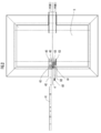
- FIG. 5B is a plan view of the load-type door opening / closing device of FIG. 5A.
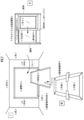
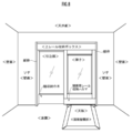
- Explanatory drawing of Example 1 which shows the example of installation of the load-type door opening / closing apparatus of this embodiment.
- Explanatory drawing of Example 2 which shows the other installation example of the load-type door opening / closing apparatus of this embodiment.
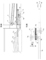
- the load type door opening and closing device is a load type door opening and closing device having an opening and closing mechanism for opening and closing the door 1, and is a sliding support rail that supports the door 1 so as to open and close.
- a door opening rail 3 provided on the door 1
- a sliding member 4 slidably attached to the door opening rail 3
- a tread plate 5 and the sliding member 4 and the tread plate 5 are coupled to each other.
- a connecting member 6 is a connecting member 6.
- FIG. 1A shows a state before the operation (a state where the door 1 is closed), and FIG. 1B shows a state after the operation (a state where the door 1 is opened).
- the door 1 is a single sliding door (single door sliding door), and suspension hooks 11 and 11 are extended at both ends on the upper side, and the suspension hooks 11 and 11 are connected to the sliding support rail 2. Rollers 12 and 12 that are rotatably supported are attached to the shaft.
- the sliding support rail 2 is a rail that is horizontally supported by a sash frame F or a building (not shown), and the door 1 is slidably supported by the sliding support rail 2 via rollers 12 and 12. Is done.
- the suspension hooks 11, 11 are provided with auxiliary rollers 13, 13 in addition to the rollers 12, 12.
- the auxiliary rollers 13, 13 are auxiliary rails provided at both ends of the sliding support rail 2. 14 and 14 function to stabilize the operation speed.
- the sliding support rail 2 is horizontal, and the suspension hook 11 is urged in the closing direction of the door 1 via the wire 16 by a constant load spring 15 (corresponding to the winding device of the present invention).
- the winding force of the wire 16 is energized as a 2 to 10 N capacity with respect to the weight of the door 1 of 20 to 100 kg), but in addition to or in place of this, a slight upward inclination in the opening direction of the door 1 (Slightly downward inclination in the closing direction) may be used.
- the closing operation can be smoothed by assisting the closing operation of the door 1.
- the door opening rail 3 is a rail inclined upward in the opening direction on the lower side of the door 1, and is configured to be slidable in a state in which the sliding member 4 is fitted.
- the rising inclination angle of the door opening rail 3 changes stepwise so that the upper end side of the door opening rail is larger and the lower end side is smaller.
- the ascending inclination angle is set to three stages, the initial stage gradient is 15 to 6 °, the next stage is 6 to 4 °, and the final stage is 4 to 2 °.
- the present invention is not limited to this, and may be two stages or four or more stages. If the upper end side as the initial stage is large and the lower end side as the final stage is small, it is continuous. The angle may be changed.
- the door opening rail 3 is built in the lower side of the door 1, and a cover that covers the outside thereof (a decorative cover that covers the lower end side of the door) is invisible to the user in a normal use state.
- the sliding member 4 is a roller that slides while being fitted to the door opening rail 3, and is pivotally attached to one end of the connecting member 6. The relationship between the sliding member 4 and the connecting member 6 will be described later in detail.
- the tread plate 5 is a flat plate that is partitioned by the door 1 and extends between the inside and the outside. It has become.
- the tread board 5 floats in a state where no person is on the tread board 5 via the return sliding member 40 that abuts the lower surface of the tread board 5 (the lower surface outside the tread board 5 in the figure).
- the return sliding member 40 is pivotally attached to one end and the arm 42 having the weight 41 provided to the other end is pivotally attached to the ground by the shaft portion 43.
- the arm 42 is slid by the weight 41 by the weight 41 when the person is not on the tread 5 due to the lever principle with the shaft portion 43 as a fulcrum.
- the closing operation opposite to the opening operation of the member 4 is performed.
- an urging means for urging the tread plate 5 upward may be provided.
- the connecting member 6 is pivotally attached to the lower surface of the tread plate 5, and the first connecting body 61 that moves in the vertical direction as the tread plate 5 moves up and down, and one end pivotally supports the sliding member 4 and the other end is the tread plate. 5 and the second connecting body 62 in contact with the lower ground GL.
- connection body 61 may be extended in the horizontal direction from the lower surface of a tread, and may be made to operate
- one end of the first connecting body 61 is connected to the tread plate 5 (in this embodiment, pivotally attached), and the second connecting body 62 is pivotally supported at the other end.
- the second connecting body 62 is pivotally attached to the first connecting body 61 at its central portion (a predetermined ratio between one end and the other end that restricts vertical movement)
- a grounding roller 63 is pivotally attached to the other end (the ground GL and the grounding point) of the second connecting body 62 and operates with the grounding roller 63 as a fulcrum.
- the sliding member 4 is connected to the second connecting body 62 through the connecting rod 60.
- the length of the connecting rod 60 can be adjusted according to the connection position with the second connecting body 62, whereby the sliding member 4 is positioned so as to be fitted to the door opening rail 3. Be able to.
- the tread board 5 floats, and correspondingly, the sliding member 4 is the highest in the vertical direction. It is fitted to the door opening rail 3 at the position (the upper end position of the door opening rail 3).
- the door 1 is displaced in the opening direction along the inclination direction of the door opening rail 3 so as to release the component force applied through the sliding member 4.
- the load of the door 1 is not applied to the sliding member 4, the load of the sliding member 4 can be reduced and the durability thereof can be improved.
- the sliding member 4 may be moved downward from the upper end side of the door opening rail 3 along the downward inclination direction of the door opening rail 3.
- the operation speed can be improved.
- the rising inclination angle on the upper end side of the door opening rail 3 is large, the downward force of the sliding member 4 acting on the door opening rail 3 is increased. The opening operation of the door 1 can be started quickly.
- the load on the sliding member 4 can be reduced to improve the durability, and the agile operation of the door 1 can be realized.
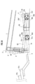
- the structure which used the gear part 70 as the connection member 6 as another load type door opening / closing apparatus of this embodiment is demonstrated.
- symbol is attached
- the connecting member 6 includes a first arm 71 having one end connected to the tread plate 5, a second arm 72 having the sliding member 4 connected to the other end, and the first arm 71 and the second arm 72.
- the gear unit 70 is provided in between and operates in opposite directions to each other.
- the gear unit 70 includes a first gear 70a and a second gear 70b.
- the first gear 70a rotates integrally with the first arm 71 by the first connecting shaft 71a.
- the second gear 70b rotates integrally with the second arm 72 by the second connecting shaft 72a.
- the first gear 70a and the second gear 70b are gears in which the first arm 71 and the second arm 72 are engaged with each other so as to rotate in opposite directions, and the diameter ratio is the operation of the first arm 71.
- the value is more than 1 times (for example, 2 to 3 times).
- the gear unit 70 is built in a space below the tread board 5 and is fixed to a pedestal (not shown).
- the first arm 71 is connected by being brought into contact with the tread plate 5 via a tread plate side roller 50 pivotally attached to one end, and a weight 71c is provided at the other end extended.
- the first arm 71 is pivotally attached to the first connecting shaft 71a at the center position.
- the second arm 72 has one end pivotally attached to the second connecting shaft 72a and the other end to which the sliding member 4 is connected.
- the mechanism in which the sliding member 4 is connected is based on the connecting rod 60 as in the above-described embodiment.
- the load type door opening and closing device configured as described above, when a person gets on the tread board 5 from a state where no person is on the tread board 5, the treading force generated on the tread board 5 passes through the tread board side roller 50.
- the first arm 71 acts on one end of the first arm 71, and the first arm 71 rotates around the first connecting shaft 71a in the clockwise direction in the drawing.
- the door 1 is displaced in the opening direction along the inclination direction of the door opening rail 3 so as to release the component force acting through the sliding member 4. At this time, since the load of the door 1 is not applied to the sliding member 4, the load of the sliding member 4 can be reduced and the durability thereof can be improved.
- the sliding member 4 may be moved downward from the upper end side of the door opening rail 3 along the downward inclination direction of the door opening rail 3.
- the operation speed can be improved.
- the load on the sliding member 4 can be reduced to improve the durability, and the agile operation of the door 1 can be realized.
- the first arm 71 in a state where no person is on the tread 5, the first arm 71 is rotated counterclockwise in the figure by the weight 71c of the first arm 71, via the tread side roller 50. It returns to the state where the tread board 5 floats.
- symbol is attached
- the connecting member 6 includes a first arm 81 whose one end is connected to the tread plate 5 and a sliding member 4 ′ (one sliding member is supported in one embodiment in this embodiment because the sliding member is one-side supported).
- a pair of cam mechanisms provided between a first arm 81 and a second arm 82 that are connected to each other and are operated in opposite directions. 83.
- the first arm 81 and the second arm 82 are rotatably supported by the shaft body 80 at predetermined positions.
- the first arm 81 is connected by being brought into contact with the tread plate 5 via a tread plate-side roller 50 pivotally attached to one end, and a weight 81c is provided at the other extended end.
- the sliding member 4 ' is connected and supported via the connecting rod 60 at the other end, as in the above-described embodiment.
- the pair of cam mechanisms 83 are elliptical first cams 83a and second cams 83b arranged on both sides of the shaft body 80.
- the cams 83a and 83b are arranged on the first arm 81 side and the second arm 82 side.
- the arms 81a and 82a and 81b and 82b protrude.
- the first cam 83a and the second cam 83b are attached to a shaft body supported by a frame provided on a pedestal (not shown), and are rotatable about the shaft body.
- the first cam 83a is in contact with the lower surface of the second arm 82 from the first cam 83a and the arm 81a protruding so as to contact the lower surface of the first arm 81 from the first cam 83a. And an arm 82a protruding to the right.
- the second cam 83b includes an arm 81b that protrudes from the second cam 83b so as to contact the lower surface of the first arm 81, and an arm 82b that protrudes from the second cam 83b to contact the lower surface of the second arm 82. And have.
- the load type door opening and closing device configured as described above, when a person gets on the tread board 5 from a state where no person is on the tread board 5, the treading force generated on the tread board 5 passes through the tread board side roller 50.
- the first arm 81 acts on one end of the first arm 81, and the first arm 81 rotates clockwise about the shaft body 80.
- the door 1 is displaced in the opening direction along the inclination direction of the opening door rail 3 so as to release the component force applied through the sliding member 4 ′.
- the load on the sliding member 4 ′ can be reduced and its durability can be improved.
- the sliding member 4 ′ may be moved downward from the upper end side of the door opening rail 3 along the downward inclination direction of the door opening rail 3. Can improve the operation speed.
- the load of the sliding member 4 ′ can be reduced to improve the durability, and the agile operation of the door 1 can be realized.
- the first arm 81 rotates counterclockwise by the weight 81c of the first arm 81 when no person is on the tread board 5.
- the arm 81a of the first cam 83a is pushed down and the arm 82a is pushed up.
- the 2nd arm 82 rotates clockwise.
- the first arm 81 rotates counterclockwise to return the tread plate 5 to the lifted state, and the second arm 82 is moved to the initial position of the sliding member 4 ′ (the upper end of the door opening rail 3).
- symbol is attached
- the configurations of the return sliding member 40, the weight 41, the arm 42, and the shaft portion 43 for returning the tread plate 5 are also omitted (the same configurations 40 to 43 as in the first embodiment are omitted).
- the connecting rod 60 is directly connected to the tread plate 5. That is, the connecting member 6 includes only a connecting rod 60 that is provided so as to extend from the tread plate 5 in the vertical direction and has one end connected to the tread plate and the other end provided with the sliding member 4 ′.
- the treading force of the tread plate 5 is directly transmitted to the sliding member 4 ′ via the connecting rod 60 integral with the tread plate 5, and the sliding member 4 ′ acts to push down the lower surface of the door opening rail 3.
- the door 1 is displaced in the opening direction along the inclination direction of the opening door rail 3 so as to release the component force applied through the sliding member 4 ′.
- the load on the sliding member 4 ′ can be reduced and its durability can be improved.
- the sliding member 4 ′ may be moved downward from the upper end side of the door opening rail 3 along the downward inclination direction of the door opening rail 3. Can improve the operation speed.
- the load of the sliding member 4 ′ can be reduced to improve the durability, and the agile operation of the door 1 can be realized.
- the level in the vertical and horizontal directions was accurately taken and fixed using a laser.
- a connecting bracket that transmits the treading force of the tread mechanism is separated from the summing stand at the summing of the aluminum alloy joinery and the tread mechanism, and the height from the bottom of the tread mechanism is ⁇ Installed and fixed with an accuracy of 0.5mm.
- a weight for restoring the tread board top plate to the original position was attached and a return metal fitting of a shape utilizing this principle was installed and fixed.
- the aluminum alloy door is suspended on the support rail, and the lower end of the door is attached to the hook part for 1 to 3 grades of door opening
- the rail was fixed to the tip of the coupling fitting.
- the transmission state of the pedaling force, the opening size of the door and the opening / closing speed were adjusted, and it was confirmed that a predetermined performance was obtained, and the work was completed.
- the door did not bounce, it operated with no problem, and no failure was confirmed.
- Lightweight fixtures and tread board mechanisms were installed in the wall openings and floor excavations, and the vertical and horizontal levels were accurately taken and fixed using a laser.
- a connecting bracket for transmitting the treading force of the tread mechanism is separated from the summing stand at the summing part of the steel lightweight joinery and the tread mechanism part, and the height from the bottom of the tread mechanism is ⁇ Installed and fixed with an accuracy of 0.5mm.
- a lever-shaped return metal fitting with a weight for restoring the tread board top plate to its original position was installed and fixed.
- the steel lightweight door After confirming the vertical movement of 20 to 30mm of the tread board top plate, the steel lightweight door is suspended on the support rail and pushed down against the door opening rail attached to the lower reinforcement of the steel lightweight door. While adjusting the height of the pin, the pin was fixed to the tip of the connection fitting. The transmission state of the pedaling force, the opening size of the door and the opening / closing speed were adjusted, and it was confirmed that a predetermined performance was obtained, and the work was completed. In response to the impact force of multiple simultaneous users, the door did not bounce, it operated with no problem, and no failure was confirmed.
- the sliding door is quickly opened in response to the stepping operation of the tread. Can be moved to. Further, the sliding door can be moved in the closing direction by using a winding device, and since a moving urging force is added by a pusher at an accelerated speed, the sliding door can be quickly opened and closed. Moreover, it is easy to ensure a wide open frontage.
- the connecting bracket with a push-down actuating rod that has one end connected to the footboard mechanism and a runner roller that is a sliding member at the other end can easily change the setting of the urging force. However, it can be automatically opened and closed, and can be moved manually in the closing direction without difficulty.
- the open / close sliding door device having such a remarkable effect is a method of opening and moving by a body load at the time of stepping on a person's stepping board, so that it is difficult to secure electric power for an electric motor, for example, an outdoor simple building such as a greenhouse It has the effect that it can be constructed easily.
- the door automatic opening / closing device for a heavy door is energy efficient and can be operated even by a user with a light weight.
- Steel light doors can be made with the size of the hook part freely, so the tilt angle and rail width of the door opening rail can be set appropriately, and the runner roller diameter can be changed from 50mm to 60mm. Since the setting of the urging force can be changed, the response is good even with a heavy door, and it can be made reliable with no failure.
Landscapes
- Engineering & Computer Science (AREA)
- Mechanical Engineering (AREA)
- Civil Engineering (AREA)
- Structural Engineering (AREA)
- Power-Operated Mechanisms For Wings (AREA)
- Wing Frames And Configurations (AREA)
- Vehicle Step Arrangements And Article Storage (AREA)
Abstract
Description
前記扉を開閉するように摺動自在に支持する摺動支持レールと、
前記扉に設けられ、該扉の開方向に上昇傾斜した開扉用レールと、
前記開扉用レールを摺動する摺動部材に連結部材を介して連結され、前記扉を踏力で開方向に動作させる踏板と
を備え、
前記扉は、閉じた状態で前記摺動部材が前記開扉用レールの上端側に配置され、開動作時に前記踏板に作用した踏力により該摺動部材が該開扉用レールに対して押し下げられ該扉が開方向に変位することを特徴とする。
前記連結部材は、
前記踏板に連結されて上下方向に動作する第1連結体と、一端が前記摺動部材に連結すると共に他端が地面に当接し、一端と他端との間で前記第1連結体に軸着された第2連結体とを備えるパンタグラフ式と、
一端が前記踏板に連結された第1アームと、他端が前記摺動部材に連結された第2アームと、前記第1アームと前記第2アームとを各々独立に軸支し、該第1アームと該第2アームとを互いに逆方向に動作させるギア部とを備えるギア式と、
一端が前記踏板に連結された第1アームと、他端が前記摺動部材に連結された第2アームと、共有の回転軸に軸支された前記第1アームと前記第2アームとの間に設けられ、該第1アームと該第2アームとを互いに逆方向に動作させる一対のカム機構とを備えるカム式と、
前記連結部材は、前記踏板から垂直方向に延設され一端が該踏板に連結すると共に他端に摺動部材が設けられた連結棒である直接押し下げ方式と
から選択されるいずれかの方式であることを特徴する。
請求項1または2記載の荷重式扉開閉装置において、
第3発明の荷重式扉開閉装置によれば、開扉用レールの上昇傾斜角度を変えることで、摺動部材が開扉用レールに作用する作用力の開扉用レール方向の分力を変えることができる。ここで、開扉用レールの上端側の上昇傾斜角度を大きくすることで、開扉用レールに作用する摺動部材の作用力の開扉用レール方向の分力を大きくすることができ、扉の開動作開始を俊敏なものとすることができる。
前記扉に連結されたワイヤの巻き取りの力によって該扉を閉方向に付勢する巻取装置を備えることを特徴とする。
本発明の一実施形態として、荷重式扉開閉装置について、図1~3を参照して説明する。
[第2実施形態]
次に、図4を参照して、本実施形態の他の荷重式扉開閉装置として連結部材6としてギア部70を用いた構成について説明する。なお、上述の実施形態と同一対象については同一の符号を付して説明を省略する。
[第3実施形態]
次に、図5を参照して、本実施形態のその他の荷重式扉開閉装置について説明する。なお、上述の実施形態と同一対象については同一の符号を付して説明を省略する。
[第4実施形態]
次に、図6を参照して、本実施形態のその他の荷重式扉開閉装置について説明する。なお、上述の実施形態と同一対象については同一の符号を付して説明を省略する。また、踏板5を復帰させるための復帰用摺動部材40、重錘41、アーム42および軸部43の構成も省略する(第1実施形態と同様の構成40~43省略する)。
Iに示すアルミニウム合金製建具:有効開口W=800mm、H=2000mmかつ枠外寸法W=1600mm、
H=2200mmの片引き引戸を製作した。また、図7のIIIに示す、底面が横556mm、縦956mm高さ70mmの上下方向を自在に変動できる天板を持った踏板機構部を製作した。これらを、図7のIに示す、建物の壁開口及び床掘り込み部の所定の位置に設置した。
置に復元させる錘をつけたてこの原理を利用した形の復帰金物を設置固定した。
使用し、組み立て状態で内法寸法0.95m×0.2mの矩形となる片引き鋼製軽量扉の枠及び扉の展開図を作成した。さらに切断加工、プレス加工、曲げ加工、扉組み立て加工、枠組立加工、錆止塗装・仕上げ塗装、仮組検査、外観及び寸法検査を経て製品化し、また底面が横556mm、縦956mm高さ70mmの上下方向を自在に変動できる天板を持った踏板機構部を製作し、製品の梱包、金具を出荷表と共に発送した。
構、83a,86…第1カム、83b,87…第2カム。
Claims (4)
- 人の体重を利用して扉を開閉させる開閉機構を備えた荷重式扉開閉装置において、
前記扉を開閉するように摺動自在に支持する摺動支持レールと、
前記扉に設けられ、該扉の開方向に上昇傾斜した開扉用レールと、
前記開扉用レールを摺動する摺動部材に連結部材を介して連結され、前記扉を踏力で開方向に動作させる踏板と
を備え、
前記扉は、閉じた状態で前記摺動部材が前記開扉用レールの上端側に配置され、開動作時に前記踏板に作用した踏力により該摺動部材が該開扉用レールに対して押し下げられ該扉が開方向に変位することを特徴とする荷重式扉開閉装置。 - 請求項1記載の荷重式扉開閉装置において、
前記連結部材は、
前記踏板に連結されて上下方向に動作する第1連結体と、一端が前記摺動部材に連結すると共に他端が地面に当接し、一端と他端との間で前記第1連結体に軸着された第2連結体とを備えるパンタグラフ式と、
一端が前記踏板に連結された第1アームと、他端が前記摺動部材に連結された第2アームと、前記第1アームと前記第2アームとを各々独立に軸支し、該第1アームと該第2アームとを互いに逆方向に動作させるギア部とを備えるギア式と、
一端が前記踏板に連結された第1アームと、他端が前記摺動部材に連結された第2アームと、共有の回転軸に軸支された前記第1アームと前記第2アームとの間に設けられ、該第1アームと該第2アームとを互いに逆方向に動作させる一対のカム機構とを備えるカム式と、
前記連結部材は、前記踏板から垂直方向に延設され一端が該踏板に連結すると共に他端に摺動部材が設けられた連結棒である直接押し下げ方式と
から選択されるいずれかの方式であることを特徴する荷重式扉開閉装置。 - 請求項1または2記載の荷重式扉開閉装置において、
開扉用レールは、扉の開方向の上昇傾斜角度が、該開扉用レールの上端側が大きく、下端側が小さいことを特徴とする荷重式扉開閉装置。 - 請求項1乃至3のうちいずれか1項記載の荷重式扉開閉装置において、
前記扉に連結されたワイヤの巻き取りの力によって該扉を閉方向に付勢する巻取装置を備えることを特徴とする荷重式扉開閉装置。
Priority Applications (6)
| Application Number | Priority Date | Filing Date | Title |
|---|---|---|---|
| CN201580020340.3A CN106232928B (zh) | 2014-04-18 | 2015-03-09 | 负载式门开关装置 |
| SG11201608302XA SG11201608302XA (en) | 2014-04-18 | 2015-03-09 | Load-type, door opening and closing device |
| EP15779661.6A EP3133233B1 (en) | 2014-04-18 | 2015-03-09 | Load-type, door opening and closing device |
| MYPI2016703766A MY183135A (en) | 2014-04-18 | 2015-03-09 | Load-type, door opening and closing device |
| US15/303,921 US10006238B2 (en) | 2014-04-18 | 2015-03-09 | Load-type door opening and closing device |
| KR1020167028317A KR101934530B1 (ko) | 2014-04-18 | 2015-03-09 | 하중식 도어 개폐 장치 |
Applications Claiming Priority (2)
| Application Number | Priority Date | Filing Date | Title |
|---|---|---|---|
| JP2014086640A JP5799358B1 (ja) | 2014-04-18 | 2014-04-18 | 荷重式扉開閉装置 |
| JP2014-086640 | 2014-04-18 |
Publications (1)
| Publication Number | Publication Date |
|---|---|
| WO2015159609A1 true WO2015159609A1 (ja) | 2015-10-22 |
Family
ID=54323825
Family Applications (1)
| Application Number | Title | Priority Date | Filing Date |
|---|---|---|---|
| PCT/JP2015/056822 Ceased WO2015159609A1 (ja) | 2014-04-18 | 2015-03-09 | 荷重式扉開閉装置 |
Country Status (9)
| Country | Link |
|---|---|
| US (1) | US10006238B2 (ja) |
| EP (1) | EP3133233B1 (ja) |
| JP (1) | JP5799358B1 (ja) |
| KR (1) | KR101934530B1 (ja) |
| CN (1) | CN106232928B (ja) |
| MY (1) | MY183135A (ja) |
| SG (1) | SG11201608302XA (ja) |
| TW (1) | TWI604121B (ja) |
| WO (1) | WO2015159609A1 (ja) |
Families Citing this family (14)
| Publication number | Priority date | Publication date | Assignee | Title |
|---|---|---|---|---|
| JP6399490B2 (ja) * | 2015-03-13 | 2018-10-03 | パナソニックIpマネジメント株式会社 | 走行補助装置及びこれを備えた引戸装置 |
| KR101939050B1 (ko) * | 2017-04-04 | 2019-01-16 | 엘에스산전 주식회사 | 배전반의 방출부 커버 |
| KR101970160B1 (ko) | 2017-09-13 | 2019-04-17 | 이선재 | 족동식 미닫이도어 개폐장치 |
| JP7202517B2 (ja) * | 2018-10-19 | 2023-01-12 | 株式会社miimo | 非電動式自動扉装置 |
| TWI710999B (zh) * | 2019-07-09 | 2020-11-21 | 中華學校財團法人中華科技大學 | 智慧多功能安全感應電動門禁系統 |
| CN111129976B (zh) * | 2020-01-19 | 2021-03-12 | 东营市南方电器有限责任公司 | 一种具有安全防护功能的改进型配电柜 |
| CN111520033B (zh) * | 2020-04-30 | 2022-07-22 | 日月峰(厦门)自动化设备有限公司 | 一种移门装置 |
| CN112145008A (zh) * | 2020-09-27 | 2020-12-29 | 芯叶(广州)网络科技有限公司 | 一种厨房推拉门用方便开门机构 |
| KR102297518B1 (ko) * | 2020-12-11 | 2021-09-02 | 최인재 | 무동력 도어 개폐장치 |
| CN113279650B (zh) * | 2021-05-21 | 2022-08-23 | 马小云 | 一种环保型装配式钢结构建筑 |
| USD1038743S1 (en) * | 2021-12-27 | 2024-08-13 | Klein Iberica, S.A.U. | Holding device for sliding doors |
| CN114414263B (zh) * | 2022-01-25 | 2024-02-20 | 鑫源汽车有限公司 | 滑门关闭速度的测量装置和最小关闭速度测试方法 |
| CN116733347A (zh) * | 2023-07-11 | 2023-09-12 | 广汽丰田汽车有限公司 | 输送链自动防尘门装置及生产线体 |
| KR102833725B1 (ko) * | 2024-05-14 | 2025-07-11 | 김광민 | 반자동형 슬라이딩 도어 시스템 |
Citations (3)
| Publication number | Priority date | Publication date | Assignee | Title |
|---|---|---|---|---|
| US1593845A (en) * | 1923-11-10 | 1926-07-27 | Holm Roy | Door-control mechanism |
| JP4253034B1 (ja) * | 2007-09-28 | 2009-04-08 | 泰雄 中野 | 扉自動開閉装置 |
| JP2012251420A (ja) * | 2011-05-11 | 2012-12-20 | Yasuo Nakano | 扉開閉装置用踏み板機構 |
Family Cites Families (14)
| Publication number | Priority date | Publication date | Assignee | Title |
|---|---|---|---|---|
| FR1543942A (fr) * | 1967-02-21 | 1968-10-31 | Mécanisme pour fermeture parallèle au plan de l'ouverture | |
| JPH0637482A (ja) | 1992-04-23 | 1994-02-10 | Toutan Seimitsu Kk | 電子部品組立用治具及びその製造方法 |
| JPH0637482U (ja) | 1992-10-24 | 1994-05-20 | 日本建鐵株式会社 | 自動開閉扉 |
| JPH07208016A (ja) | 1994-01-24 | 1995-08-08 | Koji Yabuki | 足踏扉開閉装置 |
| JPH07286476A (ja) | 1994-04-16 | 1995-10-31 | Masaki Hamada | 重力自然ドア装置 |
| JPH11324480A (ja) | 1998-05-07 | 1999-11-26 | Cosmo Tec:Kk | 踏込圧利用の自動開閉引戸装置 |
| JP2000220343A (ja) | 1999-01-29 | 2000-08-08 | Tateyama Alum Ind Co Ltd | 自動開閉戸 |
| JP2000274139A (ja) | 1999-03-24 | 2000-10-03 | Cosmo Tec:Kk | 踏込圧利用の自動開閉引戸装置 |
| JP2010019041A (ja) | 2008-07-14 | 2010-01-28 | Toto Kogyo Co Ltd | 簡易温室の半自動開ドア装置 |
| JP2010037921A (ja) | 2008-08-04 | 2010-02-18 | Kadonaka Kogyo:Kk | 引戸の開閉装置 |
| KR20120057761A (ko) | 2010-11-27 | 2012-06-07 | 마영수 | 출입자의 체중을 이용한 무전원 자동문 |
| WO2012153852A1 (ja) * | 2011-05-11 | 2012-11-15 | 株式会社K&K Company | 扉開閉装置用踏み板機構 |
| CN202659019U (zh) * | 2012-04-16 | 2013-01-09 | 田祥鑫 | 一种简易自动门 |
| JP6332675B2 (ja) | 2014-04-25 | 2018-05-30 | 株式会社ブラザーエンタープライズ | 扉開閉装置 |
-
2014
- 2014-04-18 JP JP2014086640A patent/JP5799358B1/ja active Active
-
2015
- 2015-03-09 KR KR1020167028317A patent/KR101934530B1/ko active Active
- 2015-03-09 CN CN201580020340.3A patent/CN106232928B/zh active Active
- 2015-03-09 MY MYPI2016703766A patent/MY183135A/en unknown
- 2015-03-09 US US15/303,921 patent/US10006238B2/en active Active
- 2015-03-09 SG SG11201608302XA patent/SG11201608302XA/en unknown
- 2015-03-09 WO PCT/JP2015/056822 patent/WO2015159609A1/ja not_active Ceased
- 2015-03-09 EP EP15779661.6A patent/EP3133233B1/en active Active
- 2015-03-10 TW TW104107563A patent/TWI604121B/zh active
Patent Citations (3)
| Publication number | Priority date | Publication date | Assignee | Title |
|---|---|---|---|---|
| US1593845A (en) * | 1923-11-10 | 1926-07-27 | Holm Roy | Door-control mechanism |
| JP4253034B1 (ja) * | 2007-09-28 | 2009-04-08 | 泰雄 中野 | 扉自動開閉装置 |
| JP2012251420A (ja) * | 2011-05-11 | 2012-12-20 | Yasuo Nakano | 扉開閉装置用踏み板機構 |
Also Published As
| Publication number | Publication date |
|---|---|
| TW201544672A (zh) | 2015-12-01 |
| US20170037670A1 (en) | 2017-02-09 |
| SG11201608302XA (en) | 2016-11-29 |
| CN106232928B (zh) | 2018-04-06 |
| TWI604121B (zh) | 2017-11-01 |
| KR101934530B1 (ko) | 2019-01-02 |
| KR20160138453A (ko) | 2016-12-05 |
| JP2015206189A (ja) | 2015-11-19 |
| US10006238B2 (en) | 2018-06-26 |
| EP3133233B1 (en) | 2020-03-18 |
| CN106232928A (zh) | 2016-12-14 |
| EP3133233A4 (en) | 2017-12-27 |
| JP5799358B1 (ja) | 2015-10-21 |
| MY183135A (en) | 2021-02-15 |
| EP3133233A1 (en) | 2017-02-22 |
Similar Documents
| Publication | Publication Date | Title |
|---|---|---|
| JP5799358B1 (ja) | 荷重式扉開閉装置 | |
| JP4253034B1 (ja) | 扉自動開閉装置 | |
| KR101984325B1 (ko) | 문 개폐 장치용 발판 기구 | |
| CN205348387U (zh) | 折叠式阳台装置 | |
| CN205012894U (zh) | 一种改进的磁控内置百叶中空玻璃 | |
| CN1771379B (zh) | 拉门用的闭锁装置 | |
| EP3682079B1 (en) | Pivoting window | |
| CN2536567Y (zh) | 步行上楼助力机 | |
| JP2012251420A (ja) | 扉開閉装置用踏み板機構 | |
| JP2017031738A (ja) | 無電源荷重式扉開閉装置 | |
| JP2024100631A (ja) | 自走手摺及び自走手摺の製造方法 | |
| JP2018021442A (ja) | 迅速復元機能踏台付無電源重力開扉引き戸 | |
| JP3227424U (ja) | 扉自動開閉装置 | |
| JP3253168U (ja) | 狭域用小型無電源重力開扉引き戸 | |
| CN102059692B (zh) | 机械驻足爬杆机器人 | |
| CN201062762Y (zh) | 导向式cmy混色装置 | |
| JP2017043882A (ja) | 開閉補助力具付き荷重式扉開閉装置 | |
| JP2000220343A (ja) | 自動開閉戸 | |
| CN221226965U (zh) | 一种机电安装用的电缆架设支撑装置 | |
| JP2007119121A (ja) | 段差解消機 | |
| CN213234399U (zh) | 一种建筑底部下跃型复式住宅结构 | |
| CN213475127U (zh) | 自动电动升降扶梯 | |
| RU2350786C1 (ru) | Привод скважинного штангового насоса | |
| CN2729267Y (zh) | 双玻璃门窗中夹置百叶窗的升降装置 | |
| CN104828672A (zh) | 一种用于楼道电梯内踏板的收放装置 |
Legal Events
| Date | Code | Title | Description |
|---|---|---|---|
| 121 | Ep: the epo has been informed by wipo that ep was designated in this application |
Ref document number: 15779661 Country of ref document: EP Kind code of ref document: A1 |
|
| REEP | Request for entry into the european phase |
Ref document number: 2015779661 Country of ref document: EP |
|
| WWE | Wipo information: entry into national phase |
Ref document number: 2015779661 Country of ref document: EP |
|
| ENP | Entry into the national phase |
Ref document number: 20167028317 Country of ref document: KR Kind code of ref document: A |
|
| WWE | Wipo information: entry into national phase |
Ref document number: 15303921 Country of ref document: US |
|
| NENP | Non-entry into the national phase |
Ref country code: DE |
|
| WWE | Wipo information: entry into national phase |
Ref document number: IDP00201607352 Country of ref document: ID |