WO2015182575A1 - Boîte à bornes pour modules de cellules photovoltaïques, module de cellules photovoltaïques et réseau de cellules photovoltaïques - Google Patents
Boîte à bornes pour modules de cellules photovoltaïques, module de cellules photovoltaïques et réseau de cellules photovoltaïques Download PDFInfo
- Publication number
- WO2015182575A1 WO2015182575A1 PCT/JP2015/065007 JP2015065007W WO2015182575A1 WO 2015182575 A1 WO2015182575 A1 WO 2015182575A1 JP 2015065007 W JP2015065007 W JP 2015065007W WO 2015182575 A1 WO2015182575 A1 WO 2015182575A1
- Authority
- WO
- WIPO (PCT)
- Prior art keywords
- terminal box
- solar cell
- cable
- terminal
- cell module
- Prior art date
- Legal status (The legal status is an assumption and is not a legal conclusion. Google has not performed a legal analysis and makes no representation as to the accuracy of the status listed.)
- Ceased
Links
Images









Classifications
-
- H—ELECTRICITY
- H02—GENERATION; CONVERSION OR DISTRIBUTION OF ELECTRIC POWER
- H02S—GENERATION OF ELECTRIC POWER BY CONVERSION OF INFRARED RADIATION, VISIBLE LIGHT OR ULTRAVIOLET LIGHT, e.g. USING PHOTOVOLTAIC [PV] MODULES
- H02S40/00—Components or accessories in combination with PV modules, not provided for in groups H02S10/00 - H02S30/00
- H02S40/30—Electrical components
- H02S40/34—Electrical components comprising specially adapted electrical connection means to be structurally associated with the PV module, e.g. junction boxes
-
- Y—GENERAL TAGGING OF NEW TECHNOLOGICAL DEVELOPMENTS; GENERAL TAGGING OF CROSS-SECTIONAL TECHNOLOGIES SPANNING OVER SEVERAL SECTIONS OF THE IPC; TECHNICAL SUBJECTS COVERED BY FORMER USPC CROSS-REFERENCE ART COLLECTIONS [XRACs] AND DIGESTS
- Y02—TECHNOLOGIES OR APPLICATIONS FOR MITIGATION OR ADAPTATION AGAINST CLIMATE CHANGE
- Y02E—REDUCTION OF GREENHOUSE GAS [GHG] EMISSIONS, RELATED TO ENERGY GENERATION, TRANSMISSION OR DISTRIBUTION
- Y02E10/00—Energy generation through renewable energy sources
- Y02E10/50—Photovoltaic [PV] energy
Definitions
- the present invention relates to a terminal box for a solar cell module, a solar cell module, and a solar cell array.
- the solar cell module is formed, for example, by sealing a plurality of crystalline solar cells made of single crystal silicon or polycrystalline silicon pasted on a substrate such as glass with a sealing material such as a resin material or a protective film.
- Crystal solar cell modules and thin film solar cell modules formed by sealing thin film solar cells made of thin film photoelectric conversion layers formed on a substrate such as glass with a sealing material such as a resin material or a protective film.
- a sealing material such as a resin material or a protective film
- the lead wire electrically connected to the solar battery cell is usually pulled out to the outside, and the drawn lead wire is put into a terminal box connected to the cable. It is designed to be electrically connected.
- a terminal box may be provided on the back surface of the solar cell module body or on the side surface of the solar cell module body.
- a plurality of solar cell module bodies are connected in series via a terminal box, a plurality of solar cell module bodies are connected in parallel, or in series.
- the connected solar cell module body rows are connected in parallel to obtain a desired output voltage and generated power.
- the solar cell module when the terminal box is provided on the side surface of the solar cell module body, the solar cell module is used on the ceiling or wall of a building for lighting, as well as a sunroof for a passenger car, a building window, etc. It is particularly desirable in the case of a light transmission type (so-called see-through type) thin film solar cell module that can be used in a wide range of applications.
- a light transmission type so-called see-through type
- see-through lines a large number of elongated grooves (so-called see-through lines) are formed in the power generation unit to transmit light.
- a battery module can be mentioned.
- Patent Documents 2 and 3 disclose a terminal box for a solar cell module in which one cable is connected to one end and the other cable is connected to the other end opposite to the one end. is doing.
- a terminal box can be made, for example, about the size of the width of the cable.
- a cable having a single (one-core) electric wire may be connected to the terminal box body.
- FIG. 24 is a schematic configuration diagram schematically showing an example of a connection form of a plurality of solar cell modules Ma to Ma.
- FIG. 24 shows an example in which a plurality of terminal boxes Ba to Ba are provided on the side surfaces M1 of the plurality of solar cell module bodies M to M.
- a plurality of solar cell module bodies M to M are single (one core). Are connected in series via one cable Ca1 having a single electric wire Wa and the other cable Ca2 having a single (one-core) electric wire Wb.
- the lead wires L1 and L2 are taken out from the plurality of solar cell module bodies M to M, and the taken out lead wires L1 and L2 are connected to the positive side and the negative side of the terminal boxes Ba to Ba, respectively.
- the negative electrode side is connected to a single one electric wire Wa (negative electrode electric wire) in one cable Ca1
- the positive electrode side is a single other electric wire Wb (positive electrode electric wire) in the other cable Ca2.
- one single electric wire Wa (negative electrode electric wire) in one cable Ca1 and the other single electric wire Wb (positive electrode electric wire) in the other cable Ca2 are connected to each other via a connector CNa.
- each of the one cable and the other cable has a single (one-core) electric wire, and is suitable for parallel connection of solar cell modules.
- the terminal box configuration has not been fully studied.
- an object of the present invention is to provide a terminal box for a solar cell module, a solar cell module, and a solar cell array that can realize a reduction in size of a terminal box suitable for parallel connection of solar cell modules.
- the present invention provides a terminal box, a solar cell module, and a solar cell array for the following solar cell module.
- Terminal box for solar cell module A terminal box for a solar cell module according to the present invention is positive or negative at the terminal box body, one end of the terminal box body, and the other end opposite to the one end. A pair of electric wires is provided.
- the solar cell module according to the present invention includes a solar cell module main body and a terminal box, and the terminal box is opposite to the terminal box main body, one end of the terminal box main body, and the one end.
- the other end of the side is provided with a pair of positive and negative electric wires.
- the solar cell array according to the present invention includes a plurality of solar cell modules according to the present invention, and the positive / negative pair of other solar cell modules adjacent to the positive / negative pair of electric wires of one solar cell module.
- the plurality of solar cell modules are connected in parallel by being electrically connected to the electric wire.
- a mode in which a first terminal member provided in the terminal box main body and a second terminal member having a different polarity from the first terminal member have a laminated structure can be exemplified.
- a mode in which a diode is further provided in the terminal box body can be exemplified.
- connection position of one lead wire connecting portion electrically connected to one of the pair of lead wires taken out from the solar cell module body of the solar cell module and the pair of lead wires The aspect comprised so that the connection position of the other lead wire connection part electrically connected to the other lead wire of them may align in a predetermined direction can be illustrated.
- the solar cell module surrounds at least a part of a peripheral portion of a lead wire connecting portion electrically connected to at least one of the pair of lead wires taken out from the main body of the solar cell module.
- the aspect by which the protrusion part which protruded in is provided can be illustrated.
- one cable is connected to one end of the terminal box body, and the other cable is connected to the other end opposite to the one end.
- the said other cable can illustrate the aspect provided with the said pair of positive / negative electric wires, respectively.
- the one cable and the other cable can be exemplified as a two-core integrated cable in which the pair of positive and negative wires are integrated.
- the two-core integrated cable is branched into one-core cables on the side opposite to the side connected to the terminal box body, and at the ends of the two one-core cables on the branch side,
- a pair of connectors is provided can be exemplified.
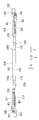
- FIG. 1 is a conceptual diagram showing an example of a connection form of a plurality of solar cell modules provided with a terminal box for a solar cell module according to an embodiment of the present invention.
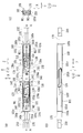
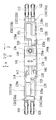
- FIG. 2 is a front view showing a schematic configuration showing an example of a terminal box according to the embodiment of the present invention.
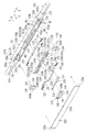
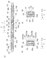
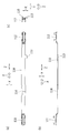
- FIG. 3 is an exploded perspective view showing a schematic configuration of a terminal box body portion in the terminal box shown in FIG. 4 is a schematic configuration diagram of a terminal box main body portion in the terminal box shown in FIG. 2, wherein (a) is a front view thereof, (b) is a first side view thereof, and (c) ) Is a second side view thereof.
- 5 is a schematic configuration diagram of a box lid in the terminal box main body shown in FIG.
- FIG. 2 is a front view thereof, (b) is a first side view thereof, and (c). Is a second side view thereof.
- 6 is a schematic cross-sectional view of a terminal box main body portion in the terminal box shown in FIG. 2, wherein (a) is a cross-sectional view taken along line AA shown in FIG.
- FIG. 4 is a cross-sectional view taken along the line BB shown in FIG. 4A, and
- FIG. 4C is a cross-sectional view taken along the line CC shown in FIG.
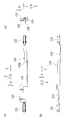
- FIG. 7 is a front view showing a schematic configuration of constituent members such as a first terminal member and a second terminal member removed from the terminal box body shown in FIG. 4.
- FIG. 8 is a perspective view showing a schematic configuration of constituent members such as a first terminal member and a second terminal member removed from the terminal box body shown in FIG.
- FIG. 9 is a schematic configuration of a first terminal member provided in the terminal box body, wherein (a) is a front view thereof, (b) is a first side view thereof, and (c) is a front view thereof. It is the 2nd side view.
- FIG. 10 is a schematic configuration of a second terminal member provided in the terminal box body, wherein (a) is a front view thereof, (b) is a first side view thereof, and (c) is a front view thereof. It is the 2nd side view.
- FIG. 9 is a schematic configuration of a first terminal member provided in the terminal box body, wherein (a) is a front view thereof, (b) is a first side view thereof, and (c) is a front view thereof. It is the 2nd side view.
- FIG. 10 is a schematic configuration of a second terminal member provided in the terminal
- FIG. 11 is a schematic configuration diagram of a spacer provided in the terminal box body, in which (a) is a front view thereof, (b) is a first side view thereof, and (c) is a diagram thereof. It is a perspective view, (d) is the 2nd side view.
- FIG. 12 is a schematic configuration diagram of a third terminal member provided in the terminal box body, wherein (a) is a front view thereof, (b) is a first side view thereof, and (c). Is a second side view thereof.
- FIG. 13 is a schematic configuration diagram of a fixing member provided in the terminal box body, in which (a) is a front view thereof, (b) is a first side view thereof, and (c) is a front view thereof.
- FIG. 14 is a schematic configuration diagram showing a branch portion portion of one cable and the other cable which are two-core integrated cables in the terminal box shown in FIG. 2, and (a) is a left side view thereof.
- (B) is a front view thereof, and (c) is a right side view thereof.
- FIG. 15 is a schematic configuration diagram showing a branched portion portion of one cable and the other cable which are two-core integrated cables in the terminal box shown in FIG. 2, and (a) is a first side view thereof.
- FIG. 14B is a cross-sectional view taken along the line AA shown in FIG. 16A and 16B are perspective views of the branch portion shown in FIGS. 14 and 15, wherein FIG.
- FIG. 16A is a perspective view of the branch portion viewed from the front side
- FIG. 16B is a rear view of the branch portion. It is the perspective view seen from the side.
- FIG. 17 is a perspective view showing the internal structure by removing the cover lid of the cover member.
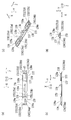
- FIG. 18 is a schematic configuration diagram illustrating another example of the terminal box according to the embodiment of the present invention, in which (a) is a front view thereof and (b) is a first side view thereof. (C) is a rear view thereof.
- FIG. 19 is a schematic configuration diagram of a terminal box main body portion in the terminal box shown in FIG. 18, wherein (a) is a front view thereof, (b) is a first side view thereof, and (c) ) Is a second side view thereof.
- FIG. 18 is a schematic configuration diagram illustrating another example of the terminal box according to the embodiment of the present invention, in which (a) is a front view thereof and (b) is a first side view thereof. (C) is a
- FIG. 20 is a schematic configuration diagram of a box lid in the terminal box body shown in FIG. 18, wherein (a) is a front view thereof and (b) is a first side view thereof.
- FIG. 21 is a schematic cross-sectional view of a terminal box main body portion in the terminal box shown in FIG. 18, wherein (a) is a cross-sectional view taken along line AA shown in FIG.
- FIG. 19 is a sectional view taken along line BB shown in FIG. 19A
- FIG. 19C is a sectional view taken along line CC shown in FIG. 19A
- FIG. FIG. 20A is a cross-sectional view taken along the line DD shown in FIG. 19A
- FIG. 19E is a cross-sectional view taken along the line EE shown in FIG. FIG.
- FIG. 22 is a schematic configuration diagram showing a branched portion portion of one cable and the other cable that are two-core integrated cables in the terminal box shown in FIG. 18, and (a) is a front view thereof. (B) is the 1st side view, (c) is the back view, (d) is the right side view.
- FIG. 23 is a schematic configuration diagram showing a branch portion portion of one cable and the other cable which are two-core integrated cables in the terminal box shown in FIG. 18, and FIG. FIG. 22B is a cross-sectional view taken along the line AA shown in FIG. 22B, FIG. 22B is a cross-sectional view taken along the line BB shown in FIG. 22A, and FIG. FIG. 22D is a sectional view taken along the line CC, and FIG. 22D is a sectional view taken along the line DD shown in FIG.
- FIG. 24 is a schematic configuration diagram schematically illustrating an example of a connection form of a plurality of solar cell modules.
- FIG. 1 is a conceptual diagram showing an example of a connection form of a plurality of solar cell modules MO to MO provided with a terminal box 100 for a solar cell module according to an embodiment of the present invention.
- FIG. 1 shows an example in which terminal boxes 100 to 100 are provided on side surfaces M1 of a plurality of solar cell module bodies M to M.
- a solar cell array 400 is composed of a plurality of solar cell modules MO to MO.
- Each of the solar cell modules MO to MO includes a solar cell module body M and a terminal box 100.
- the solar cell array 400 includes a plurality of solar cell modules MO, and among the solar cell modules MO to MO, another solar cell module MO in which a pair of positive and negative electric wires W1, W2 of one solar cell module MO is adjacent.
- a plurality of solar cell modules MO to MO are connected in parallel by being electrically connected to the pair of positive and negative electric wires W1, W2.
- the pair of positive and negative electric wires is simply referred to as “a pair of electric wires”.
- the terminal boxes 100 to 100 are configured such that a plurality of solar cell module bodies M to M can be connected in parallel.
- the plurality of solar cell modules MO to MO are connected in parallel via one cable 210 having a pair (two-core) of wires W1 and W2 and the other cable 220 having a pair (two-core) of wires W1 and W2.
- the lead wires L1 and L2 are taken out from the plurality of solar cell module bodies M to M, and the lead wire L1 on the positive electrode side of the lead wires L1 and L2 taken out is the diode 140 (in this example, a block king diode).
- the lead wire L2 on the negative electrode side is connected to the negative electrode side of the terminal boxes 100 to 100.
- the positive electrode side and the negative electrode side are respectively connected to a pair of electric wires (one electric wire W1 (positive electric wire in this example) and the other electric wire W2 (negative electric wire in this example)) in one cable 210.
- the other cable 220 is connected to a pair of electric wires (one electric wire W1 (positive electric wire in this example) and the other electric wire W2 (negative electric wire in this example)).
- a pair of wires in one cable 210 (one wire W1 (positive wire in this example) and the other wire W2 (in this example, negative wire)) and a pair of wires in the other cable 220 (one wire W1 ( In this example, the positive electric wire) and the other electric wire W2 (in this example, the negative electric wire) are connected to each other via the connector pair 300,300.
- the plurality of solar cell modules MO to MO have the same configuration.
- the terminal box 100 according to the present embodiment can configure a solar cell module power cable 200 by connecting a plurality of solar cell module bodies M to M to each other.
- FIG. 2 is a front view showing a schematic configuration showing an example of the terminal box 100 according to the embodiment of the present invention.
- FIG. 3 is an exploded perspective view showing a schematic configuration of the terminal box body 101 portion in the terminal box 100 shown in FIG.
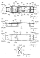
- FIG. 4 is a schematic configuration diagram of a terminal box body 101 portion in the terminal box 100 shown in FIG. 4 (a) is a front view thereof, FIG. 4 (b) is a first side view thereof, and FIG. 4 (c) is a second side view thereof.
- FIG. 4 shows a state of the terminal box body 101 with the box lid 102 removed.
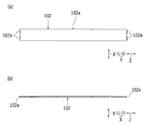
- FIG. 5 is a schematic configuration diagram of the box lid 102 in the terminal box body 101 shown in FIG.
- FIG. 5 (a) is a front view thereof
- FIG. 5 (b) is a first side view thereof
- FIG. 5 (c) is a second side view thereof.
- FIG. 6 is a schematic cross-sectional view of the terminal box body 101 portion in the terminal box 100 shown in FIG. 6A is a cross-sectional view taken along the line AA shown in FIG. 4A, and FIG. 6B is a cross-sectional view taken along the line BB shown in FIG. 4A.
- FIG. 6C is a cross-sectional view taken along the line CC shown in FIG. FIG. 6 shows a state in which the box lid 102 is provided.
- FIG. 7 and 8 are a front view and a perspective view, respectively, showing a schematic configuration of components such as the first terminal member 110 and the second terminal member 120 removed from the terminal box body 101 shown in FIG.
- FIG. 9 is a schematic configuration of the first terminal member 110 provided in the terminal box body 101.
- FIG. 9A is a front view thereof
- FIG. 9B is a first side view thereof
- FIG. 9C is a second side view thereof.
- FIG. 10 is a schematic configuration of the second terminal member 120 provided in the terminal box body 101.
- 10 (a) is a front view thereof
- FIG. 10 (b) is a first side view thereof
- FIG. 10 (c) is a second side view thereof.
- FIG. 11 is a schematic configuration diagram of the spacer 130 provided in the terminal box main body 101.
- 11 (a) is a front view thereof
- FIG. 11 (b) is a first side view thereof
- FIG. 11 (c) is a perspective view thereof
- FIG. 11 (d) is a perspective view thereof.
- FIG. 12 is a schematic configuration diagram of the third terminal member 150 provided in the terminal box body 101.
- FIG. 12A is a front view thereof
- FIG. 12B is a first side view thereof
- FIG. 12C is a second side view thereof.
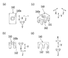
- FIG. 13 is a schematic configuration diagram of a fixing member 160 provided in the terminal box main body 101.
- 13 (a) is a front view thereof
- FIG. 13 (b) is a first side view thereof
- FIG. 13 (c) is a perspective view thereof
- FIG. 13 (d) is a perspective view thereof. It is a 2nd side view.
- a terminal box 100 for a solar cell module includes a terminal box main body 101 and one end portion 100a of the terminal box main body 101 (FIGS. 2, 3, 4A, 4B, and FIG. 6 (a)) and the other end 100b opposite to the one end 100a (see FIGS. 2, 3, 4 (a), 4 (b) and 6 (a)), respectively.
- a pair of electric wires (W1, W2), (W1, W2) (refer to FIG. 2, FIG. 3, FIG. 4 (a) and FIG. 4 (c)) are provided.
- the terminal box 100 includes one cable 210 and the other cable 220 (see FIGS. 2 to 4 and 6A) and a terminal box body 101 (see FIGS. 2 to 4 and 6). I have.
- Both the one cable 210 and the other cable 220 include a pair of electric wires W1 and W2.
- a cable pair in which two one-core cables are independent from each other, or a two-core integrated cable in which a pair (two-core) electric wires are integrated can be used as the one cable 210 and the other cable 220.
- one cable 210 and the other cable 220 are two-core integrated cables in which a pair of (two-core) electric wires are integrated.
- One cable 210 and the other cable 220 have a pair of electric wires W1 and W2 having the same configuration, and the size in the first direction X and the size in the second direction Y are the same or substantially the same. .
- the terminal box main body 101 has one cable insertion portion 101a (see FIGS. 4A and 6A) through which one cable 210 is inserted, and the other cable insertion portion 101b through which the other cable 220 is inserted (see FIG. 3 and FIG. 4 (a) and FIG. 6 (a)).
- the terminal box 100 is configured such that one cable 210 is connected to one end portion 100a of the terminal box body 101 and the other cable 220 is connected to the other end portion 100b.
- One cable insertion portion 101a in the terminal box main body 101 is configured to insert one cable 210 from one end portion 100a.
- the other cable insertion portion 101b in the terminal box main body 101 is configured to insert the other cable 220 from the other end portion 100b.
- one cable insertion portion 101a and the other cable insertion portion 101b are both insertion holes, and the center of one cable insertion portion 101a and the center of the other cable insertion portion 101b are in the insertion direction Z. Are lined up on a virtual straight line.
- the terminal box 100 includes a first terminal member 110 (see FIGS. 3, 4A, 6, 7, 8, and 9) and a second terminal member 120 having a polarity different from that of the first terminal member 110. (See FIGS. 3, 4A, 6, 7, 8, and 10).
- the first terminal member 110 and the second terminal member 120 are provided in the terminal box main body 101.
- the first terminal member 110 and the second terminal member 120 have a laminated structure.
- the first terminal member 110 is provided in the terminal box main body 101 and is electrically connected to one electric wire W1 of the pair of electric wires W1 and W2 of the one cable 210 inserted through the terminal box main body 101.
- One terminal 111 (see FIGS. 3, 4A, 7, 8, 9A and 9B) connected to the terminal box 101 and the other cable inserted into the terminal box body 101 It has the other terminal 112 (refer FIG.3, FIG.4 (a), FIG.7, FIG.8 and FIG.9) electrically connected to one electric wire W1 of a pair of 220 electric wires W1, W2. .
- the second terminal member 120 is provided in the terminal box main body 101 and is electrically connected to the other electric wire W2 of the pair of electric wires W1, W2 of the one cable 210 inserted through the terminal box main body 101.
- One terminal 121 see FIGS. 3, 4A, 7, 8, 10A, and 10B
- the other terminal 122 (refer to FIG. 3, FIG. 4 (a), FIG. 7, FIG. 8, and FIG. 10) that is electrically connected to the other of the wires W ⁇ b> 1 and W ⁇ b> 2.
- first terminal member 110 one terminal 111 is electrically connected to one electric wire W ⁇ b> 1 of one cable 210 inserted from one end portion 100 a of the terminal box main body 101, and the other terminal 112 is connected to the terminal box main body 101. It is electrically connected to one electric wire W1 of the other cable 220 inserted from the other end 100b.
- second terminal member 120 one terminal 121 is electrically connected to the other electric wire W ⁇ b> 2 of one cable 210 inserted from one end 100 a of the terminal box body 101, and the other terminal 122 is connected to the terminal box body 101. It is electrically connected to the other electric wire W2 of the other cable 220 inserted from the other end 100b.
- the first terminal member 110 and the second terminal member 120 are both made of a metal material.
- the first terminal member 110 and the second terminal member 120 are plate-shaped.
- the terminal box body 101 is made of a resin material.
- the terminal box 100 includes a direction in which the pair of electric wires W1 and W2 on one side and the pair of electric wires W1 and W2 on the other side are provided (in this example, the insertion direction Z), and one of the pair of electric wires W1 and W2.
- a direction specifically orthogonal or substantially orthogonal to both the direction in which the electric wire W1 and the other electric wire W2 are juxtaposed (the first direction X in this example) (in the second direction Y in this example)
- the first terminal member 110 and the second terminal member 120 are laminated.
- the pair of wires W1 and W2 of one cable 210 and the pair of wires W1 and W2 of the other cable 220 both pass through the one cable 210 and the other cable 220.
- the first terminal member 110 and the second terminal member 120 are arranged in both the insertion direction Z and the first direction X.
- the first terminal member 110 and the second terminal member 120 intersect in the insertion direction Z (in this example, orthogonal or substantially orthogonal). They are stacked in the second direction Y that intersects (in this example, orthogonal or substantially orthogonal).
- one cable 210 is inserted into the terminal box body 101 so that an imaginary straight line connecting the axes of the pair of electric wires W1 and W2 is parallel or substantially parallel to the first direction X, and the other cable 220 is inserted. Is inserted into the terminal box body 101 so that an imaginary straight line connecting the axes of the pair of electric wires W1, W2 is parallel or substantially parallel to the first direction X.
- predetermined plane portions that are parallel or substantially parallel to both the first direction X and the insertion direction Z are stacked in the second direction Y.
- the insertion direction Z is the longitudinal direction of the one cable 210 and the other cable 220 (in this example, the longitudinal direction of the terminal box body 101), and more specifically, the center of the one cable insertion portion 101a and the other cable.
- the direction is a straight line connecting the center of the insertion part 101b.
- the terminal box body 101 has a hexahedral box shape that is open in one direction (in this example, one side in the second direction Y).
- the terminal box body 101 includes a box lid 102 (see FIGS. 2, 3, 5, and 6) that closes the open side of the terminal box body 101.
- the box lid 102 is engaged with the terminal box main body 101 in an uneven manner.
- a plurality of engaging protrusions 102a to 102a that engage with the terminal box body 101 are provided on the outer peripheral portion of the box lid 102.
- the plurality of engaging convex portions 102a to 102a are provided at two locations on both sides of the box lid 102 in the insertion direction Z and at one location on one side of the box lid 102 in the first direction X.
- a plurality of engagement recesses 101c to 101c (see FIGS. 3 and 4A) that engage with the plurality of engagement projections 102a to 102a, respectively, are provided on the inner peripheral portion on the open side of the terminal box body 101.
- the box lid 102 is fitted on the open side of the terminal box main body 101, and the plurality of engaging convex portions 102a to 102a are engaged with the plurality of engaging concave portions 101c to 101c in the terminal box main body 101, respectively.
- the open side of the main body 101 is closed.
- the box lid 102 is made of a resin material.
- the terminal box body 101 has a long shape in the insertion direction Z.
- the terminal box body 101 has one outer surface (installation surface 101d) (see FIGS. 3, 4, and 6) in the first direction X fixed to the side surface M1 (see FIG. 1) of the solar cell module body M. It has become.
- the size d1 (see FIG. 3) of the terminal box body 101 in the second direction Y is equal to or less than the thickness of the solar cell module body M (in this example, about the thickness of the solar cell module body M).
- the second direction Y is the thickness direction of the solar cell module body M.
- the first terminal member 110 and the second terminal member 120 extend in the insertion direction Z and are provided in the terminal box main body along the insertion direction Z.
- the one terminal 111 and the other terminal 112 in the first terminal member 110 are provided on a virtual straight line along the insertion direction Z.
- the one terminal 121 and the other terminal 122 in the second terminal member 120 are provided on an imaginary straight line along the insertion direction Z.
- the connection position of one terminal 111 in the first terminal member 110 and the connection position of one terminal 121 in the second terminal member 120 are configured to be aligned or substantially aligned in the second direction Y (FIG. 8). reference).
- the connection position of the other terminal 112 in the first terminal member 110 and the connection position of the other terminal 122 in the second terminal member 120 are configured to be aligned or substantially aligned in the second direction Y (see FIG. 8).
- the outer ends in the insertion direction Z of one terminal 111 in the first terminal member 110 and one terminal 121 in the second terminal member 120 are configured to be aligned or substantially aligned in the insertion direction Z (see FIGS. 7 and 8). ).
- the outer terminals 112 in the insertion direction Z of the other terminals 112 in the first terminal member 110 and the other terminals 122 in the second terminal member 120 are configured to be aligned or substantially aligned in the insertion direction Z (see FIGS. 7 and 8).
- the first terminal member 110 and the second terminal member 120 have the same or substantially the same size in the insertion direction Z.
- the height of the terminal box body 101 (in this example, the size d2 in the first direction X (see FIG. 3)) is 20 mm or less (preferably 15 mm or less, more preferably 14 mm or less). .
- the size d1 in the second direction Y is smaller than the size d2 in the first direction X.
- the size d1 of the terminal box main body 101 in the second direction Y can exemplify 10 mm or less, and the size of the terminal box main body 101 in the insertion direction Z can exemplify 130 mm or less.
- the terminal box 100 is provided in the terminal box main body 101 and is a spacer 130 (FIGS. 3 and 4) that electrically insulates the first terminal member 110 and the second terminal member 120 from each other. (A), FIG.6, FIG.7, FIG.8 and FIG. 11) are further provided.
- the spacer 130 includes a holding portion that holds the first terminal member 110 and the second terminal member 120, and the holding portion also serves as an insulating portion.
- the spacer 130 has a central portion 130a in the first direction X from one outer side in the first direction X (see FIGS. 3, 6B, 7, 11A, and 11C).
- a first insertion guide groove 131 (in this example, first insertion guide grooves 131a and 131b on both sides in the insertion direction Z) (see FIGS. 3, 7, 8, and 11).
- a first restricting portion 132 (in this example, first restricting portions 132a and 132b on both sides in the insertion direction Z) for restricting the outward movement of the first terminal member 110 in the first direction X (FIGS. 3, 7 and 7). 8, 11 (a), 11 (c) and 11 (d)).
- the first insertion guide groove 131 is formed along the insertion direction Z, and both ends of the first direction X and the insertion direction Z are open. Accordingly, the spacer 130 is moved by the first insertion guide groove 131 (131a, 131b) and the first restricting portion 132 (132a, 132b) to both sides in the second direction Y and the first direction X. The movement of the terminal box 100 to both sides can be restricted, and the assembly workability of the terminal box 100 can be improved accordingly.
- the spacer 130 has a second insertion guide groove 133 (the other end in the insertion direction Z in this example) through which the second terminal member 120 is inserted from the other outer side in the first direction X toward the central portion 130a in the first direction X.
- a second insertion guide groove 133 (Second insertion guide groove on the side of the portion 100b) (see FIGS. 3, 7, 8, and 11) and a second restricting portion 134 that restricts the outward movement of the second terminal member 120 in the first direction X (see FIG. In this example, it has 2nd control part 134a, 134b (refer FIG.3, FIG.7, FIG.11) in the both sides of the insertion direction Z.
- 2nd control part 134a, 134b (refer FIG.3, FIG.7, FIG.11) in the both sides of the insertion direction Z.
- the second insertion guide groove 133 is formed along the insertion direction Z, and both ends of the first direction X and the insertion direction Z are open. Accordingly, the spacer 130 moves the second terminal member 120 to both sides in the second direction Y and moves to both sides in the first direction X by the second insertion guide groove 133 and the second restricting portion 134 (134a, 134b). As a result, the assembly workability of the terminal box 100 can be improved accordingly.
- the spacer 130 is made of a resin material having excellent insulating properties (for example, PPE resin: polyphenylene ether resin).
- the spacer 130 has a long shape in the insertion direction Z.
- the spacer 130 has a size d3 (see FIG. 11A) in the first direction X that is a predetermined length longer than the size between the inner walls in the first direction X of the terminal box body 101 so that the spacer 130 is surely fit in the terminal box body 101.
- the size in the insertion direction Z is set to a size that is (slightly) smaller than the size between the inner walls in the insertion direction Z of the terminal box body 101 by a predetermined length.
- the spacer 130 has a size (thickness) that is as thin as possible in the second direction Y, and the insulation and retention of the first terminal member 110 and the second terminal member 120 (and the third terminal member 150 described later). The size (thickness and shape) can be maintained.
- the spacer 130 has a positioning portion 135 (see FIGS. 3, 6B, 11A, and 11C) that is positioned with respect to the terminal box body 101 within the terminal box body 101. Is provided. Further, in the terminal box body 101, a positioning unit 135 that controls the movement of the spacer 130 in the first direction X and the insertion direction Z by the positioning unit 135 positions the positioning unit 135 (see FIGS. 3 and 6B). In the position. Thereby, the assembly workability
- the positioning part 135 (135a, 135b) is a pair of through-holes penetrating in the second direction Y on both sides of the spacer 130 in the first direction X.
- the restricting portion 103 (103a, 103b) is a protruding portion that protrudes inward in the second direction Y on both sides in the first direction X of the side surface of the terminal box body 101.
- the diameter of the restricting portion 103 (103a, 103b) is set to a size (slightly) smaller than the diameter of the positioning portion 135 (135a, 135b) to the extent that the positioning portion 135 can be smoothly inserted.
- the restricting portion 103 (103a, 103b) is integrally formed with the terminal box body 101.
- the first terminal member 110 is provided with a positioning portion 113 (see FIG. 3, FIG. 6A and FIG. 9) that is positioned with respect to the spacer 130. Thereby, the assembly workability
- the positioning portion 113 is a protruding portion that protrudes to one side in the first direction X, and is locked to a locking portion 130b (see FIG. 6A) of the spacer 130. . Thereby, the first terminal member 110 can restrict movement in the insertion direction Z by the positioning portion 113.
- the positioning portion 113 is integrally formed with the first terminal member 110.
- the one terminal 111 and the other terminal 112 in the first terminal member 110 are fixed by crimping one electric wire W1 in one cable 210 and one electric wire W1 in the other cable 220, respectively.
- one terminal 111 and another terminal 112, one electric wire W1, and one electric wire W1 are further fixed by solder.
- the second terminal member 120 is provided with a positioning portion 120a (see FIGS. 3 and 10A) that is positioned with respect to the spacer 130.
- the positioning portion 120a is a curved portion that is curved at 90 degrees or substantially 90 degrees between the first direction X and the insertion direction Z in the plate-like portion along both the first direction X and the insertion direction Z. It is latched by the latching
- FIG. Thereby, the 2nd terminal member 120 can control the movement in the insertion direction Z by the positioning part 120a.
- the one terminal 121 and the other terminal 122 in the second terminal member 120 are fixed by crimping the other electric wire W2 in one cable 210 and the other electric wire W2 in the other cable 220, respectively.
- the one terminal 121 and the other terminal 122, the other electric wire W2, and the other electric wire W2 are further fixed by solder.
- the terminal box 100 includes a diode 140 (blocking diode in this example) provided in the terminal box body 101 (see FIGS. 3, 4A, 6A, 7 and 8). ).
- the diode 140 includes a diode main body 141, two terminals 142 and 143, and a heat radiating portion 144.
- the diode body 141 is provided with two terminals 142 and 143 protruding in the same direction, and a heat radiating portion 144 is provided on the opposite side to the direction in which the two terminals 142 and 143 protrude.
- the two terminals 142 and 143 are directed to one side in the insertion direction Z (one end 100a side in this example), while the heat radiating portion 144 is the other side in the insertion direction Z (the other end 100b side in this example). It is provided in the terminal box main body 101 (in this example, the spacer 130) so as to face.
- the diode 140 has a protrusion 136 (see FIGS. 3 and 4) provided in the spacer 130 in a holding hole 144 a (see FIGS. 3, 6 (a) and 7) provided in the heat radiating portion 144.
- FIG. 6 (a), FIG. 7, FIG. 8 and FIG. 11) are penetrated and fixed by a fixing portion 136a (see FIG. 4 (a), FIG. 7 and FIG. 8).
- the protrusion 136 is integrally formed with the spacer 130.
- the terminal box body 101 has a pair of lead wire insertion holes 101e and 101f (FIGS. 3 and 4B) through which the pair of lead wires L1 and L2 taken out from the solar cell module body M (see FIG. 1) are respectively inserted. Reference) is provided.
- the pair of lead wire insertion holes 101e and 101f are sized by a predetermined value (slightly) larger than the cross-sectional shape of the lead wires L1 and L2 so that the lead wires L1 and L2 can be smoothly inserted.
- One of the first terminal member 110 and the second terminal member 120 (in this example, the first terminal member 110) is inserted into one of the pair of lead wire insertion holes 101e and 101f of the terminal box body 101. It is configured to be electrically connected via a diode 140 to one lead wire L1 of the pair of lead wires L1 and L2 inserted through the hole 101e.
- One of the first terminal member 110 and the second terminal member 120 is the other lead wire insertion of the pair of lead wire insertion holes 101e, 101f of the terminal box body 101. It is configured to be electrically connected to the other lead wire L2 of the pair of lead wires L1 and L2 inserted through the hole 101f.
- the terminal box 100 includes a third terminal member 150 (FIG. 3, FIG. 4 (a), FIG. 6 (a), FIG. 6 (c), FIG. 7, FIG. 8, and FIG. 12).
- the third terminal member 150 is made of a metal material.
- the third terminal member 150 is plate-shaped.
- the first terminal member 110, the second terminal member 120, and the third terminal member 150 are stacked in the second direction Y.
- the first terminal member 110, the second terminal member 120, and the third terminal member 150 are laminated in the second direction Y with predetermined plane portions that are parallel or substantially parallel to both the first direction X and the insertion direction Z. ing.
- the third terminal member 150 has one lead wire connecting portion 151 (FIG. 3, FIG. 4A) that is electrically connected to one lead wire L1 inserted through one lead wire insertion hole 101e of the terminal box body 101. ) In FIG. 6 (a), FIG. 6 (c), FIG. 7, FIG. 8 and FIG. 12) and one terminal 142 of the diode 140 (in this example, the anode side).
- One diode connection part 152 see FIGS. 3, 8, 12A and 12B).
- One of the first terminal member 110 and the second terminal member 120 (in this example, the first terminal member 110) is the other electrically connected to the other terminal 143 (in this example, the cathode side) of the diode 140.
- the diode connection portion 114 (see FIGS. 3, 4A, 7, 8, 9A, and 9B).
- One of the first terminal member 110 and the second terminal member 120 (the second terminal member 120 in this example) is connected to the other lead wire L2 inserted from the other lead wire insertion hole 101f of the terminal box body 101.
- the other lead wire connecting portion 123 (see the hatched portion in FIGS. 3 and 4A, FIGS. 6A, 7, 8, and 10) is electrically connected.
- one diode connecting portion 152 in the third terminal member 150 is a bent convex portion that is bent so as to protrude toward the one terminal 142 side of the diode 140.
- one diode connection part 152 and one terminal 142 of the diode 140 can be easily electrically connected by a connection member such as solder.
- one diode connection portion 152 is in the second direction in the first direction X at the same or substantially the same position as the one terminal 121 and the other terminal 122 in the second terminal member 120.
- Y it is located at the same or substantially the same position as the diode connection part 114 in the first terminal member 110, and further, at the same or substantially the same position in the insertion direction Z as the other diode connection part 114 in the first terminal member 110. positioned.
- the third terminal member 150 extends from one diode connection portion 152 toward the other end portion 100b in the insertion direction Z, bends so as to be displaced toward the open side of the terminal box body 101 in the second direction Y, and In the first direction X, one lead wire connecting portion 151 is formed by being displaced toward the first terminal member 110 side.
- the other diode connection portion 114 in the first terminal member 110 is a bent convex portion that is bent so as to protrude toward the other terminal 143 of the diode 140. Thereby, the other diode connection part 114 and the other terminal 143 of the diode 140 can be easily electrically connected by a connection member such as solder.
- the first terminal member 110 is bent at both ends in the insertion direction Z so as to be displaced toward one electric wire W1 (one cable 210) and one electric wire W1 (the other cable 220) in the second direction Y. Terminals 111 and other terminals 112 are formed. Thereby, the connection position in the 2nd direction Y with one terminal 111 and the other terminal 112, one electric wire W1 (one cable 210), and one electric wire W1 (the other cable 220) can be match
- connection form in which the two terminals 142 and 143 of the diode 140 are respectively connected to the one diode connection part 152 in the third terminal member 150 and the other diode connection part 114 in the first terminal member 110 is limited thereto.
- a connection form by soldering, a connection form by caulking, a connection form by ultrasonic waves, or a connection form combining at least two of these can be exemplified.
- the two terminals 142 and 143 of the diode 140 are connected to one diode connection portion 152 and the other diode connection portion 114 by solder.
- the terminal box 100 includes a connection position of one lead wire connecting portion 151 and a pair of leads electrically connected to one lead wire L1 of the pair of lead wires L1 and L2 taken out from the solar cell module body M.
- the connection position of the other lead wire connecting portion 123 that is electrically connected to the other lead wire L2 of the wires L1 and L2 is configured to be aligned or substantially aligned in a predetermined direction (second direction Y in this example). ing.
- connection position of the other lead wire connection portion 123 in the second terminal member 120 is the same or substantially the same position in the second direction Y as the connection position of the one lead wire connection portion 151 in the third terminal member 150. is doing. That is, one lead wire connection portion 151 and the other lead wire connection portion 123 are provided so that the connection positions in the second direction Y are aligned or substantially aligned.
- connection position of the other lead wire connection portion 123 in the second terminal member 120 is located at the same or substantially the same position in the first direction X as the connection position of the one lead wire connection portion 151 in the third terminal member 150. ing. That is, one lead wire connecting portion 151 and the other lead wire connecting portion 123 are provided so that the connection positions in the first direction X are aligned or substantially aligned. Specifically, the connection position of one lead wire connection portion 151 and the connection position of the other lead wire connection portion 123 are provided so as to be located on an imaginary straight line along the insertion direction Z.
- the pair of lead wire insertion holes 101e and 101f extend along the insertion direction Z, and are provided so that the insertion positions in the second direction Y are aligned or substantially aligned. Specifically, the pair of lead wire insertion holes 101e and 101f are provided so as to be positioned on a virtual straight line along the insertion direction Z. The pair of lead wire insertion holes 101e and 101f are connected to one lead wire of the terminal box body 101 to such an extent that the pair of lead wires L1 and L2 do not come into contact with one lead wire connecting portion 151 and the other lead wire connecting portion 123.
- the pair of lead wires L1 and L2 are inserted into the pair of lead wire insertion holes 101e and 101f as they are in a straight state, respectively, and connected to one lead wire connecting portion 151 and the other lead wire connecting portion 123, respectively. be able to.
- one of the first terminal member 110 and the second terminal member 120 (in this example, the second terminal member 120) one terminal 121 and the other terminal 122 are virtual straight lines along the insertion direction Z.
- a bent portion 124 (see FIGS. 3, 4 (b), 6 (b), 7, 8, and 10) formed by bending at 90 degrees or substantially 90 degrees in one direction is provided. .
- the second terminal member 120 is bent so as to be displaced from the other lead wire connection portion 123 toward the other electric wire W2 (one cable 210) side in the second direction Y on the one end portion 100a side in the insertion direction Z.
- One terminal 121 is formed.
- the second terminal member 120 is outside the two terminals 142 and 143 of the diode 140 in the second direction Y on the other end 100b side in the insertion direction Z from the other lead wire connection portion 123 (the open side of the terminal box body 101).
- To be displaced so as to be displaced to one inner wall of the terminal box body 101 in this example, the inner wall 101g on the installation surface 101d side) (FIGS.
- the second terminal member 120 is further bent at 90 degrees or substantially 90 degrees so as to surround the two terminals 142 and 143 of the diode 140 and the spacer 130 to form a bent portion 124.
- the second terminal member 120 has a bent portion 124 extending toward the other end portion 100b in the insertion direction Z, and a spacer 130 on the side opposite to the side bent at 90 ° or substantially 90 ° on the one end portion 100a side. It bends again by 90 degrees or substantially 90 degrees toward the side, and becomes parallel or substantially parallel to the other lead wire connecting portion 123.
- the second terminal member 120 further extends toward the other end portion 100b in the insertion direction Z and is bent so as to be displaced toward the other electric wire W2 (the other cable 220) in the second direction Y to form the other terminal 112. is doing. That is, the bent portion 124 is formed so as to avoid the diode 140 and the third terminal member 150. Further, the second terminal member 120 is bent at both ends in the insertion direction Z so as to be displaced toward the other electric wire W2 (one cable 210) and the other electric wire W2 (the other cable 220) in the second direction Y.
- the connection position in Y can be matched.
- a portion corresponding to the bent portion 124 of the inner wall of the terminal box body 101 has a recess or a through hole (in this example, a through hole 101h (FIG. 3). 4 (b) and 6 (b))
- the bent portion 124 is a recess or a through-hole (this hole in the inner wall of the terminal box body 101 (in this example, the inner wall 101g of the installation surface 101d).
- wiring is performed in a state of entering the through hole 101h)
- the bent portion 124 does not protrude outward from the terminal box main body 101.
- the recessed portion or the through hole has a shape corresponding to the bent portion 124.
- the shape of the bent portion 124 is such that the bent portion 124 can smoothly enter. There is a size only (slightly) larger size.
- each of these members is formed by a plurality of members.
- the electrical resistance tends to increase at the contact portions between them and the area where the area of each member is reduced, and it becomes difficult to allow a relatively large current.
- the first terminal member 110, the second terminal member 120, and the third terminal member 150 are formed by integrally forming a metal plate by cutting and bending, respectively.
- the thickness of the 1st terminal member 110, the 2nd terminal member 120, and the 3rd terminal member 150 is made the same or substantially the same.
- the spacer 130 electrically insulates between the first terminal member 110 and the second terminal member 120, and between the first terminal member 110 and the third terminal member 150 and the second terminal member 120.
- the third terminal member 150 is electrically insulated from the third terminal member 150.
- the spacer 130 has a pair of mounting portions 138 and 139 (FIGS. 3, 4A, and 6A) on which one lead wire connecting portion 151 and the other lead wire connecting portion 123 are respectively mounted. 7, 8 and 11).
- one placement portion 138 on which one lead wire connection portion 151 is placed is the other terminal 112 and the second terminal member 120 of the first terminal member 110 in the insertion direction Z.
- the other mounting portion 139 that is provided between the other terminal 122 and the diode 140 and on which the other lead wire connecting portion 123 is mounted is connected to one terminal 111 of the first terminal member 110 in the insertion direction Z and It is provided between one terminal 121 of the second terminal member 120 and the diode 140.
- the terminal box body 101 is electrically connected to at least one of the pair of lead wires L1 and L2 (L1 and / or L2) taken out from the solar cell module body M.
- Protruding portions (138a and / or 139a) are provided to protrude so as to surround at least a part of the peripheral edge portion of the lead wire connecting portion (151 and / or 123).
- one protruding portion 138a protruding from the thickness of one lead wire connecting portion 151 so as to surround at least a part of the peripheral edge portion of one lead wire connecting portion 151 (FIGS. 3A and 3B). 4 (a), FIG. 7, FIG. 8 and FIG. 11) and the other protrusion protruding from the thickness of the other lead wire connecting portion 123 so as to surround at least a part of the peripheral edge portion of the other lead wire connecting portion 123.
- a portion 139a is provided.
- one protrusion 138 a and the other protrusion 139 a are provided on the spacer 130.
- the one projecting portion 138a is provided in a straight line along the outer peripheral portion of the one lead wire connecting portion 151 placed on the one placing portion 138 at the peripheral portion of the one placing portion 138.
- the other protruding portion 139a is provided in a straight line along the outer peripheral portion of the other lead wire connecting portion 123 mounted on the other mounting portion 139 at the periphery of the other mounting portion 139.
- One protrusion 138 a and the other protrusion 139 a are integrally formed with the spacer 130.
- the pair of electric wires W1, W2 of one cable 210 and the pair of electric wires W1, W2 of the other cable 220 are both arranged in the first direction X, and the first terminal member 110 and the first Although the two terminal members 120 (and the third terminal member 150) are stacked in the second direction Y, the present invention is not limited to this.
- the terminal box 100 is provided in the terminal box body 101, and the insertion portion of one cable 210 (a pair of electric wires W1 and W2 in this example) and the insertion portion of the other cable 220 (this In the example, a pair of fixing members 160 and 160 (see FIGS. 3, 4A, 6A, and 13) for fixing the pair of electric wires W1 and W2) to the terminal box body 101 are further provided. .
- the pair of fixing members 160 and 160 are a pair of press contact portions 161 and 162 (FIGS. 3 and 13B to 13D) that press contact the pair of electric wires W1 and W2 to the terminal box body 101, respectively. ))).
- the fixing member 160 is made of a resin material.
- the one end portion 100a of the terminal box body 101 is provided with restriction portions 101i and 101i for restricting movement of the one fixing member 160 toward the other end portion 100b in the insertion direction Z (FIGS. 3 and 4A). )) Is provided.
- the one fixing member 160 has a size in the insertion direction Z such that the one fixing member 160 can be surely accommodated in the terminal box main body 101, and between the restriction portions 101i, 101i and the inner wall on the one end 100a side in the insertion direction Z of the terminal box main body 101. The size is smaller than the distance by a predetermined length (slightly).
- the terminal box main body 101 restricts the movement of both sides in the insertion direction Z of the one fixing member 160 between the restriction portions 101i, 101i and the inner wall on the one end portion 100a side in the insertion direction Z of the terminal box main body 101. be able to.
- the one fixing member 160 has a size in the first direction X so that it can be surely accommodated in the terminal box body 101 by a predetermined length than the distance between both inner walls in the first direction X of the terminal box body 101. (Slightly) small size.
- the terminal box body 101 can restrict the movement of one fixing member 160 on both sides in the first direction X between the inner walls in the first direction X of the terminal box body 101.
- the other end portion 100b of the terminal box body 101 has restriction portions 101j and 101j for restricting movement of the other fixing member 160 toward the one end portion 100a in the insertion direction Z (see FIGS. 3 and 4A). Is provided.
- the other fixing member 160 has a size in the insertion direction Z such that the other fixing member 160 fits securely in the terminal box body 101 and the inner wall on the other end 100b side in the insertion direction Z of the terminal box body 101. The size is (slightly) smaller than the distance between them by a predetermined length.
- the terminal box main body 101 restricts the movement of both sides in the insertion direction Z of the other fixing member 160 between the restriction portions 101j, 101j and the inner wall on the other end 100b side in the insertion direction Z of the terminal box main body 101. can do.
- the one fixing member 160 has a size in the first direction X so that it can be surely accommodated in the terminal box body 101 by a predetermined length than the distance between both inner walls in the first direction X of the terminal box body 101. (Slightly) small size. Thereby, the terminal box body 101 can restrict the movement of the other fixing member 160 on both sides in the first direction X between the inner walls in the first direction X of the terminal box body 101.
- the pair of pressure contact portions 161 and 162 have an inverted U-shaped concave shape that covers the pair of electric wires W1 and W2 from the open side of the terminal box body 101 in the second direction Y.
- the pair of press contact portions 161 and 162 gradually decreases in size in the first direction X from the concave-shaped open end toward the side opposite to the open end.
- the pair of fixing members 160 and 160 cover the pair of electric wires W1 and W2 so as to cover the pair of press contact portions 161 and 162, respectively, and press the pair of fixing members 160 and 160 toward the pair of electric wires W1 and W2 in the second direction Y.
- the pair of press contact portions 161 and 162 can be securely fixed to the terminal box body 101 while the pair of electric wires W1 and W2 are sandwiched.
- the pair of fixing members 160, 160 are provided with through holes 160a, 160a (see FIGS. 3, 4A and 13A to 13C) penetrating in the second direction Y. ing.
- the one end portion 100a and the other end portion 100b of the terminal box body 101 are provided with projecting portions 101k and 101k (see FIGS. 3 and 4A) projecting toward the open side in the second direction Y.
- the pair of fixing members 160, 160 are inserted through the projecting portions 101k, 101k in the one end portion 100a and the other end portion 100b of the terminal box main body 101 through the through holes 160a, 160a, and by a predetermined fixing means (in this example, an adhesive). Fixed.
- the pair of fixing members 160, 160 sandwiching the pair of electric wires W1, W2 can be fixed to the terminal box body 101.
- the terminal box body 101 is provided with air vent holes (in this example, lead wire insertion holes 101e and 101f and through holes 101h) through which air in the terminal box body 101 is released when the filler is introduced.
- air vent holes in this example, lead wire insertion holes 101e and 101f and through holes 101h
- each above-mentioned structural member is assembled
- the main body 101 is filled with a filler, and a box lid 102 is attached to the terminal box main body 101.
- the terminal box 100 is provided adjacent to the terminal box main body 101 and seal members 170 and 170 (FIGS. 2, 3, 4, and 4) that seal one cable 210 and the other cable 220. 6 (a)).
- seal members 170 and 170 FGS. 2, 3, 4, and 4
- strength of the vicinity of the terminal box main body 101 in the one cable 210 and the other cable 220 can be improved.
- the sealing member 170 for example, a shrinkable tube provided with an adhesive (so-called shrinkable tube with adhesive) can be used.
- one cable 210 and the other cable 220 are both two-core integrated cables as described above, but in this embodiment, the side connected to the terminal box body 101 Is bifurcated so that the opposite side is divided into one-core cables, and at the ends of the two one-core cables (211, 212), (221, 222) (see FIG. 2) on the branch side, Connector pairs 300, 300 (see FIG. 2) are provided.
- the connector pair 300 includes one connector 301 (a male connector in this example) and the other connector 302 (a female connector in this example).
- One one-core cable 211, 221 in one cable 210 and the other cable 220 includes one electric wire W1.
- the other one-core cables 212 and 222 in the one cable 210 and the other cable 220 include the other electric wire W2.
- the pair of connectors 301 and 302 provided on one cable 210 and the pair of connectors 302 and 301 provided on the other cable 220 are configured to be connectable.
- the terminal box 100 is configured to connect one one-core cable 211 in one cable 210 and one one-core cable 221 in the other cable 220, and the other one-core cable in the one cable 210.
- 212 and the other one-core cable 222 of the other cable 220 are connected to each other, and one one-core cable 211 of the one cable 210 is connected to one connector 301 of the pair of connectors 301, 302.
- the other one-core cable 212 of the one cable 210 is provided with the other connector 302 of the pair of connectors 301 and 302.
- One one-core cable 221 in the other cable 220 is provided with the other connector 302 of the pair of connectors 301, 302, and the other one-core cable 222 in the other cable 220 has a pair of connectors One of the connectors 301 and 302 is provided.
- One connector 301 and the other connector 302 in one cable 210 have different connector shapes, and one connector 301 and the other connector 302 in the other cable 220 have different connector shapes.
- the pair of connectors 301 and 302 in one cable 210 and the pair of connectors 301 and 302 in the other cable 220 are of the same type.
- the length of one one-core cable 211 and the other one-core cable 212 of one cable 210 that is a two-core integrated cable are different. Further, the length of one divided one-core cable 221 and the other one-core cable 222 of the other cable 220 that is a two-core integrated cable is different.
- the shorter one-core cable 211 of the one cable 210 and the longer one-core cable 221 of the other cable 220 can be connected, and the longer one of the one cable 210 is connected.
- the one-core cable 212 and the shorter one-core cable 222 of the other cable 220 can be connected.
- the shorter one-core cable 211 of one cable 210 and the longer one-core cable 221 of the other cable 220 are connected, the shorter one-core cable 211 and the longer one-core cable 221 And the longer one-core cable 212 of one cable 210 and the shorter one-core cable 222 of the other cable 220 are connected to each other.
- the total length with the core cable 222 is equal or substantially equal.
- the length of the shorter one-core cable 211 of one cable 210 and the shorter one-core cable 222 of the other cable 220 are equal or substantially equal, and the one cable 210
- the longer one-core cable 212 of the other cable 220 and the longer one-core cable 221 of the other cable 220 are equal or substantially equal.
- the shape of the connector 302 is the same as that of the connector 302 provided on the longer one-core cable 212 of the one cable 210 and the connector 302 provided on the longer one-core cable 221 of the other cable 220.
- the connector shape is the same shape.
- the color arrangement of the one one-core cable 211 and the other one-core cable 212 which are divided into one cable 210 which is a two-core integrated cable is different.
- One color of the one-core cable 221 and the other one-core cable 222 of the other cable 220 that is a two-core integrated cable are different in color scheme.
- one one-core cable 211 of one cable 210 and one one-core cable 221 of the other cable 220 have the same color
- the other one-core cable 212 of the one cable 210 and the other cable 220 are the same.
- the other one-core cable 222 has the same color.
- FIG. 14 and FIG. 15 are schematic configuration diagrams showing a branching portion 230 portion in one cable 210 and the other cable 220 which are two-core integrated cables in the terminal box 100 shown in FIG.
- FIG. 14A is a left side view thereof
- FIG. 14B is a front view thereof
- FIG. 14C is a right side view thereof.
- FIG. 15A is a first side view thereof
- FIG. 15B is a cross-sectional view taken along the line AA shown in FIG. 14B.
- FIG. 16 is a perspective view of the branching portion 230 shown in FIGS. 14 and 15.
- FIG. 16A is a perspective view of the branching portion 230 viewed from the front side
- FIG. 16B is a perspective view of the branching portion 230 viewed from the rear side.
- FIG. 17 is a perspective view showing the internal structure by removing the cover lid 242 of the cover member 240. 14 to 17, one cable 210 and the other cable 220 are shown in one drawing.
- the terminal box 100 is provided on the branch portion 230 of the one cable 210 and the other cable 220 that are two-core integrated cables, and covers the entire branch portion 230.
- the branch portion 230 is a base portion where one one-core cables 211 and 221 and the other one-core cables 212 and 222 are branched with respect to the two-core integrated cables 210a and 220a.
- the cover member 240 of one cable 210 passes through the two-core integrated cable 210a of one cable 210 at one end, and one one-core cable 211 at the other end opposite to the one end.
- the other one-core cable 212 is inserted.
- the cover member 240 of the other cable 220 is inserted through the two-core integrated cable 220a of the other cable 220 into one end, and the one-core cable 221 and the other end at the other end opposite to the one end.
- the single-core cable 222 is inserted.
- the cover member 240 includes a cover main body 241.
- the cover main body 241 has a first insertion portion 241a through which the two-core integrated cables 210a and 220a are inserted from one end, and one one-core cables 211 and 221 and the other one-core cables 212 and 222 from the other end.
- One one-core cables 211 and 221 and the other one-core cables 212 and 222 are inserted through two-core integrated cables 210a and 220a, one one-core cables 211 and 221 and the other one-core cables 212 and 222. They are arranged in parallel in a first direction X that intersects Z (in this example, orthogonal or substantially orthogonal).
- the first insertion portion 241a is located in the first direction X between the one one-core cables 211 and 221 and the other one-core cables 212 and 222 (in this example, the central portion).
- the shape of the branching portion 230 is a Y-shape when viewed from the front
- the cover member 240 is a shape that matches the Y-shape when viewed from the front.
- the cover body 241 is first in a hexahedral box shape in which one direction (for example, one side of the second direction Y intersecting (in this example, orthogonal or substantially orthogonal) in both the first direction X and the insertion direction Z) is open.
- the size in the direction X is made smaller as going to the two-core integrated cables 210a, 220a side.
- the cover main body 241 includes a cover lid 242 that closes the open side of the cover main body 241.
- the cover lid 242 has a shape in front view that matches the shape of the cover main body 241 in front view, and is fixed to the cover main body 241 by a predetermined fixing means (for example, an adhesive).
- a predetermined fixing means for example, an adhesive
- the terminal box 100 is provided adjacent to the cover member 240 and seals the two-core integrated cables 210a and 220a, one one-core cables 211 and 221 and the other one-core cables 212 and 222.
- Seal members 250 to 250 are further provided. Accordingly, the cover member 240 can be reliably fixed to the bifurcated portions 230 of the two-core integrated cables 210a and 220a, the one-core cables 211 and 221 and the other one-core cables 212 and 222.
- a shrinkable tube provided with an adhesive can be used as the sealing member 250.
- the cover main body 241 further includes a plurality of drain holes 241g to 241g (see FIGS. 14B and 16B) through which water that has entered the cover main body 241 escapes.
- the drain holes 241g to 241g are provided on the back side.
- the drain holes 241g to 241g are provided at positions corresponding to the two-core integrated cables 210a and 220a, one one-core cables 211 and 221 and the other one-core cables 212 and 222.
- the drain holes 241g to 241g are provided at both ends in the insertion direction Z.
- one connecting portion 201 in the vicinity of the branching portion 230 (a position separated by a predetermined distance), one connecting portion 201 (FIG. 14 (b) )) And the other connecting portion 202 (see FIGS. 14B and 15A) in which the other one-core cables 212 are electrically connected to each other.
- one connecting portion 201 that electrically connects one one-core cables 221 and the other one-core cable 222 are electrically connected.
- the other connection part 202 connected in general is provided.
- one connection portion 201 and the other connection portion 202 are both connected by being crimped by a crimp terminal.
- the cover member 240 is configured to cover the entire branch portion 230 including the one connection portion 201 and the other connection portion 202.
- the terminal box 100 further includes seal members 260 to 260 (see FIG. 17) that seal the one connection portion 201 and the other connection portion 202.
- seal member 260 for example, a shrink tube provided with an adhesive (so-called shrink tube with adhesive) can be used.
- the terminal box 100 further includes seal members 270 to 270 (see FIG. 17) that seal both ends of the seal members 260 to 260 in the insertion direction Z. Thereby, the penetration
- the seal member 270 for example, a water stop material can be used.
- the cover main body 241 is configured such that one side of the one-core cables 211 and 221 and the other one-core cables 212 and 222 with respect to the one connection portion 201 and the other connection portion 202 is the cover main body 241.
- the first fixing member 241e (see FIG. 17) to be fixed to one side, the other one-side cables 211, 221 and the other side of the other one-core cables 212, 222 on the basis of one connection portion 201 and the other connection portion 202
- a second fixing member 241f (see FIG. 17) for fixing to the cover main body 241.
- a pair of slits S and S (see FIG. 17) extending along the second direction Y are formed in the first fixing member 241e and the second fixing member 241f.
- the first fixing member 241e sandwiches one side of the one-core cables 211 and 221 and the other one-core cables 212 and 222 between the pair of slits S and S, respectively.
- One side of the other one-core cables 212 and 222 can be securely fixed to the cover body 241.
- the second fixing member 241f sandwiches one side of the one-core cables 211 and 221 and the other side of the other one-core cables 212 and 222 between the pair of slits S and S, respectively.
- the other side of the other one-core cables 212 and 222 can be securely fixed to the cover body 241.
- the first fixing member 241e and the second fixing member 241f are integrally formed with the cover body 241.
- FIG. 18 is a schematic configuration diagram illustrating another example of the terminal box 100 according to the embodiment of the present invention.
- 18 (a) is a front view thereof
- FIG. 18 (b) is a first side view thereof
- FIG. 18 (c) is a rear view thereof.
- FIG. 19 is a schematic configuration diagram of a terminal box body 101 portion in the terminal box 100 shown in FIG.
- FIG. 19A is a front view thereof
- FIG. 19B is a first side view thereof
- FIG. 19C is a second side view thereof.
- 18 and 19 show the state of the terminal box body 101 with the box lid 102 removed.
- FIG. 20 is a schematic configuration diagram of the box lid 102 in the terminal box body 101 shown in FIG.
- FIG. 20A is a front view thereof
- FIG. 20B is a first side view thereof.
- FIG. 21 is a schematic cross-sectional view of the terminal box body 101 portion of the terminal box 100 shown in FIG. 21A is a cross-sectional view taken along the line AA shown in FIG. 19A, and FIG. 21B is a cross-sectional view taken along the line BB shown in FIG. 19A.
- FIG. 21 (c) is a cross-sectional view taken along the line CC shown in FIG. 19 (a)
- FIG. 21 (d) is a cross-sectional view taken along the line DD shown in FIG. 19 (a).
- FIG. 21 (e) is a cross-sectional view taken along the line EE shown in FIG. 19 (a).
- FIGS. 22 and 23 are schematic configuration diagrams showing a branching portion 230 portion of one cable 210 and the other cable 220 that are two-core integrated cables in the terminal box 100 shown in FIG. 18.
- 22 (a) is a front view thereof
- FIG. 22 (b) is a first side view thereof
- FIG. 22 (c) is a rear view thereof
- FIG. 22 (d) is a rear view thereof.
- 23A is a cross-sectional view taken along the line AA shown in FIG. 22A
- FIG. 23B is a cross-sectional view taken along the line BB shown in FIG.
- FIG. 23 (c) is a cross-sectional view taken along line CC shown in FIG. 22 (a)
- FIG. 23 (d) is a cross-sectional view taken along line DD shown in FIG. 22 (a).
- FIG. 22 and 23, one cable 210 and the other cable 220 are shown in one figure.
- the terminal box 100 according to the second embodiment is different from the terminal box 100 shown in FIGS. 2 to 17 in that partition portions 180 and 180 are provided in the terminal box body 101 (18 (a), FIG. 19 (a)). 21 (a) and 21 (e)), and in addition to inserting the bent portion 124 in the second terminal member 120, the air vent which releases air when the filler is introduced into the terminal box body 101.
- the difference is that a through hole 101h (see FIGS. 3, 4B, and 6B) that also functions as a hole is not provided (see FIGS. 18B and 19B).
- the terminal box 100 according to the second embodiment further includes one or a plurality (two in this example) of partition portions 180 and 180 provided in the terminal box main body 101.
- the partition portions 180 and 180 are connected to the terminal members (in this example, the first terminal member 110 and the second terminal member 120) and the connection portions 190 and 190 of the electric wires W1 and W2 (FIG. 18A).
- FIG. 19 (a) and FIG. 21 (a)) center part).
- the partitioning portion 180 on one side and the partitioning portion 180 on the other side are plate-shaped partition plates along both the first direction X and the second direction Y.
- the shape of the partitioning portion 180 on one side and the partitioning portion 180 on the other side is the same as the shape constituting the inner wall of the terminal box body 101 when viewed from the second side surface.
- the partitioning part 180 on one side and the partitioning part 180 on the other side are attached in close contact with the inner wall of the terminal box body 101.
- the one-side partitioning portion 180 and the other-side partitioning portion 180 are located inward in the insertion direction Z by a predetermined distance including the connecting portions 190 and 190 from the end portions (both end portions in this example) of the terminal box body 101. It is provided in the position.
- the partition portions 180 and 180 are provided between the connection portions 190 and 190 and the pair of placement portions 138 and 139 in the spacer 130.
- the partition parts 180 and 180 are formed of a resin material.
- the terminal box main body 101 is provided with a pair of restricting portions 101m and 101n for restricting movement of the partitioning portion 180 in the insertion direction Z.
- the pair of restricting portions 101m and 101n are provided on both sides in the first direction X of the inner wall of the terminal box body 101 with a predetermined amount (slightly) larger than the thickness of the partitioning portion 180 so that the partitioning portion 180 can be inserted. It has been. Thereby, the restricting portions 101m and 101n can restrict the movement of the partition portion 180 in the insertion direction Z.
- the pair of restricting portions 101m and 101n are projecting portions protruding inward in the first direction X from the inner walls on both sides in the first direction X of the terminal box body 101.
- the pair of restricting portions 101m and 101n are provided integrally with the terminal box body 101.
- the terminal box body 101 according to the second embodiment has a through hole 101h (see FIGS. 3, 4B, and 6B) provided in the terminal box 100 according to the first embodiment. Therefore, since the bent portion 124 of the second terminal member 120 cannot enter the through hole 101h, the size d2 in the first direction X of the terminal box body 101 according to the second embodiment (FIG. 19 ( c) is larger than the size d2 (see FIG. 3) in the first direction X of the terminal box body 101 according to the first embodiment by that amount (specifically, about 1 mm).
- connection parts 190 and 190 of the terminal member In this example, the 1st terminal member 110 and the 2nd terminal member 120
- the electric wires W1 and W2. Is filled with a filler (see the hatched portion in FIG. 18A).
- the terminal box 100 according to the second embodiment after the above-described constituent members are assembled, first, a filler ( The hatched portion in FIG. 18A is filled and filled, and the connecting portions 190 and 190 are sealed.
- the lead wires L1 and L2 of the solar cell module body M are connected to one lead wire connecting portion 151 and the other lead wire connecting portion 123, respectively.
- the filler is charged into the inner portion ⁇ partitioned by the partitioning portions 180 and 180 in the terminal box body 101, and the terminal box body 101 is further filled with the box lid 102. Is installed.
- the terminal boxes 100 to 100 are configured to connect the plurality of solar cell modules MO to MO in parallel.
- the terminal box is configured to connect the plurality of solar cell modules MO to MO in series.
- 100 to 100 may be configured.
- the terminal boxes 100 to 100 are configured so that the first terminal member 110 is a positive electrode and the second terminal member 120 is a negative electrode.
- the first terminal member 110 is a negative electrode and the second terminal
- the terminal boxes 100 to 100 may be configured so that the member 120 is a positive electrode.
- the terminal box 100 is provided on the side surface M1 of the solar cell module main body M, but may be provided on the back surface of the solar cell module main body M.
- the solar cell module MO provided with the terminal box 100 according to the first to fifth embodiments is not particularly limited, but it is a thin film from the viewpoint that the rated voltage is higher than that of the crystalline solar cell module and desired for parallel connection. It is preferable to use a solar cell module.
- Solar cell module MO especially a light transmissive type, so-called see-through type thin film solar cell module in which a large number of elongated grooves (so-called see-through lines) and dots are formed to transmit light to the power generation unit so as to transmit light
- see-through lines elongated grooves
- the terminal box 100 includes the terminal box main body 101, the one end portion 100a of the terminal box main body 101, and the other side opposite to the one end portion 100a. Since the end portion 100b is provided with the pair of electric wires W1 and W2, respectively, the pair of electric wires W1 and W2 can be aligned in a predetermined direction (in this example, the insertion direction Z), and therefore suitable for parallel connection of the solar cell modules MO.
- the terminal box 100 can be downsized. Further, even when the pair of electric wires W1 and W2 are connected to the terminal box body 101, the terminal box 100 can be downsized.
- the terminal box 100 is configured such that one cable 210 is connected to one end 100a of the terminal box body 101, and the other cable 220 is connected to the other end 100b opposite to the one end 100a. Even if one cable 210 and the other cable 220 are each provided with a pair (two-core) of electric wires W1, W2, the terminal box 100 can be reduced in size.
- the solar cell array 400 includes a plurality of solar cells by electrically connecting a pair of electric wires W1 and W2 of one solar cell module MO to a pair of electric wires W1 and W2 of another adjacent solar cell module MO. Even when the modules MO to MO are connected in parallel, the plurality of solar cell modules MO to MO can be efficiently arranged.
- the terminal box 100 having such a configuration is provided particularly on the side surface M1 of the solar cell module body M, or / and when the solar cell module MO is a light transmission type (so-called see-through type) solar cell module, or / Furthermore, when the solar cell module MO is a thin film solar cell module, it can be used suitably.
- the terminal box 100 is configured such that one cable 210 is connected to one end portion 100a and the other cable 220 is connected to the other end portion 100b opposite to the one end portion 100a.
- the terminal box body 101 having one cable insertion portion 101a for inserting one cable 210 from the portion 100a and the other cable insertion portion 101b for inserting the other cable 220 from the other end portion 100b, a terminal box In the configuration in which the size of the main body 101 can be reduced, and thus the one cable 210 and the other cable 220 are each provided with a pair of (two-core) electric wires W1, W2. It becomes possible to realize downsizing.
- the terminal box 100 has a laminated structure in which the first terminal member 110 provided in the terminal box body 101 and the second terminal member 120 having different polarities from the first terminal member 110 are laminated. As a result, the space in the terminal box body 101 can be used effectively, whereby the terminal box 100 can be further reduced in size.
- the terminal box 100 includes a terminal box body 101 having one cable insertion portion 101a through which one cable 210 is inserted, and the other cable insertion portion 101b through which the other cable 220 is inserted, and a terminal box body.
- One terminal 111 provided in the terminal 101 and electrically connected to one electric wire W1 of the pair of electric wires W1 and W2 of the one cable 210 inserted through the terminal box main body 101, and the terminal box main body
- the first terminal member 110 having the other terminal 112 electrically connected to one of the pair of electric wires W1 and W2 of the other cable 220 inserted through the terminal 101 and the terminal box main body 101 are provided. And the other of the pair of electric wires W1 and W2 of one cable 210 inserted through the terminal box body 101.
- the second terminal member 120 having 122, and the first terminal member 110 and the second terminal member 120 have a laminated structure, so that the size of the terminal box body 101 can be reduced.
- one cable 210 and the other cable 220 are each provided with a pair (two-core) of electric wires W1 and W2, it is possible to reduce the size of the terminal box 100.
- the terminal box 100 has a configuration in which one cable 210 is connected to one end 100a and the other cable 220 is connected to the other end 100b opposite to the one end 100a.
- One cable insertion portion 101a in the terminal box main body 101 passes one cable 210 from the one end portion 100a, and the other cable insertion portion 101b in the terminal box main body 101 extends from the other end portion 100b to the other cable. 220 is inserted.
- the terminal box 100, the one cable 210, and the other cable 220 can be arranged on a virtual straight line along the solar cell module main body M.
- the solar cell module MO is installed in a building window. It can be used for a wide range of applications.
- the pair of electric wires W1 and W2 of the one cable 210 and the pair of electric wires W1 and W2 of the other cable 220 are both inserted through the one cable 210 and the other cable 220 in the insertion direction Z.
- the first terminal member 110 and the second terminal member 120 are stacked in a second direction Y that intersects both the insertion direction Z and the first direction X.
- the pair of electric wires W1 and W2 of the one cable 210 and the pair of electric wires W1 and W2 of the other cable 220 are both arranged in parallel in the first direction X.
- the size in the two directions Y can be set to the size of the width of one cable 210 and the other cable 220.
- the size of the terminal box body 101 can be reduced accordingly. Therefore, the size of the terminal box 100 can be made about the size of a conventional terminal box to which a cable having a single (one-core) electric wire is connected.
- the terminal box 100 is provided in the side surface M1 of the solar cell module main body M, and the size of the 2nd direction Y of the terminal box main body 101 is made into the thickness of the solar cell module main body M or less. .
- the terminal box body 101 can be prevented from protruding from the solar cell module body M in the thickness direction of the solar cell module body M.
- the terminal box 100 may be covered with a frame member that holds the solar cell module main body M.
- the solar cell module body M provided on the side surface M1 is framed. It becomes difficult to fit into the member, and therefore the workability of attaching the solar cell module body M to the frame member is deteriorated.
- the height of the terminal box body 101 (specifically, the size in the first direction X) is 20 mm or less (preferably 15 mm or less, more preferably 14 mm or less).
- the terminal box 100 when the terminal box 100 is covered by a frame member that holds the solar cell module body M, the terminal box 100 is inserted into the frame member when the solar cell module body M provided on the side surface M1 is fitted.
- the solar cell module main body M can be easily fitted into the frame member, whereby the workability of attaching the solar cell module main body M to the frame member can be improved.
- one of the first terminal member 110 and the second terminal member 120 (the second terminal member 120 in this example) and the other terminal 122 are connected to one cable 210 and It is provided on a virtual straight line along the insertion direction Z through which the other cable 220 is inserted, and is formed between the one terminal 121 and the other terminal 122 by being bent so as to retract from the virtual straight line.
- a bent portion 124 is provided.
- a recessed portion or a through hole (in this example, a through hole 101h) is formed in a portion corresponding to the bent portion 124 of the inner wall 101g of the terminal box body 101, and the bent portion 124 is Wiring is carried out in a state of entering a recess or a through hole (in this example, through hole 101h) in the inner wall 101g of the terminal box body 101.
- the space of the bent portion 124 can be secured by the recess or the through hole (in this example, the through hole 101h), and thereby the size of the terminal box body 101 can be maintained.
- the terminal box 100 further includes a spacer 130 that is provided in the terminal box body 101 and electrically insulates between the first terminal member 110 and the second terminal member 120. Yes.
- the spacer 130 includes a holding portion that holds the first terminal member 110 and the second terminal member 120, and the holding portion also serves as an insulating portion.
- the spacer 130 not only has insulation, but also when the first terminal member 110 and the second terminal member 120 are mounted in the terminal box body 101, the first terminal member 110 and the second terminal member 120 are provided. Can be securely held in the terminal box main body 101, and the workability of attaching the first terminal member 110 and the second terminal member 120 into the terminal box main body 101 can be improved accordingly.
- a diode that is electrically connected to a solar cell module is normally electrically connected in a forward direction between the solar cell module and an output destination (for example, a load or a storage battery).
- a blocking diode (backflow prevention diode) or a bypass diode that is electrically connected so as to be in a direction opposite to the polarity of the solar cell module is provided in parallel with the solar cell module.
- the terminal box 100 further includes a diode 140 in the terminal box body 101.
- the diode 140 can be provided in the terminal box main body 101, whereby the connection form of the solar cell module MO can be simplified.
- the terminal box body 101 is provided with a pair of lead wire insertion holes 101e and 101f through which the pair of lead wires L1 and L2 taken out from the solar cell module body M are inserted.
- One of the first terminal member 110 and the second terminal member 120 (in this example, the first terminal member 110) is one lead of the pair of lead wire insertion holes 101e and 101f of the terminal box body 101. Electrically connected via diode 140 to one of the pair of lead wires L1 and L2 (in this example, lead wire L1) inserted through the wire insertion hole (in this example, lead wire insertion hole 101e).
- One of the first terminal member 110 and the second terminal member 120 is the other lead of the pair of lead wire insertion holes 101e and 101f of the terminal box body 101.
- the diode 140 can be reliably provided in the terminal box body 101.
- the terminal box 100 further includes a third terminal member 150 provided in the terminal box main body 101, and the third terminal member 150 extends from one lead wire insertion hole 101 e of the terminal box main body 101.
- One lead wire connection portion 151 electrically connected to one inserted lead wire L1, and one diode connection portion 152 electrically connected to one terminal 142 of the diode 140;
- One of the first terminal member 110 and the second terminal member 120 has the other diode connection portion 114 that is electrically connected to the other terminal 143 of the diode 140.
- the other of the first terminal member 110 and the second terminal member 120 (in this example, the second terminal member 120) is the other of the terminal box body 101. Having other lead wire connecting portion 123 to be electrically connected to the lead wire insertion hole inserted through the other lead wire from 101f L2.
- one of the first terminal member 110 and the second terminal member 120 (the first terminal member 110 in this example) is connected to one lead via the diode 140 using the third terminal member 150. It is possible to connect to the line L1, thereby easily connecting one of the first terminal member 110 and the second terminal member 120 (in this example, the first terminal member 110), the diode 140, and one lead wire L1. It is possible to reliably wire with a simple configuration.
- the terminal box 100 is electrically connected to one lead wire L1 of the pair of lead wires L1 and L2 taken out from the solar cell module body M of the solar cell module MO.
- the connecting position of the lead wire connecting portion 151 and the connecting position of the other lead wire connecting portion 123 electrically connected to the other lead wire L2 of the pair of lead wires L1 and L2 are in a predetermined direction (in this example, the first It is configured to be aligned or substantially aligned in the two directions Y).
- the pair of lead wires L1 and L2 can be easily connected to the one lead wire connecting portion 151 and the other lead wire connecting portion 123, respectively.
- the terminal box 100 is provided in the terminal box main body 101 and electrically insulates the first terminal member 110, the second terminal member 120, and the third terminal member 150 from each other.
- a spacer 130 is provided.
- the first terminal member 110, the second terminal member 120, and the third terminal member 150 can be reliably electrically insulated.
- the spacer 130 is provided with a pair of mounting portions 138 and 139 for mounting one lead wire connecting portion 151 and the other lead wire connecting portion 123, respectively.
- connection form for connecting the pair of lead wires L1 and L2 to the one lead wire connection part 151 and the other lead wire connection part 123, respectively is not limited thereto, but, for example, a connection form by soldering or caulking A connection form, a connection form by ultrasonic waves, or a connection form combining at least two of these can be exemplified.
- solder when connecting a pair of lead wires L1 and L2 to one lead wire connecting portion 151 and the other lead wire connecting portion 123 by soldering, the solder is connected to one lead wire connecting portion 151 and the other lead wire, respectively. It may flow down to the outside of the connection part 123.
- a protruding portion (138a and / or 139a) protruding so as to surround at least a part of the peripheral edge portion of the lead wire connecting portion (151 and / or 123) electrically connected to, for example.
- the solder can be held by the corresponding protruding portion (138a and / or 139a). This effectively prevents the solder from flowing out of at least one of the lead wire connections (151 and / or 123). It is possible to stop.
- one protruding portion 138a protruding from the thickness of one lead wire connecting portion 151 so as to surround at least a part of the peripheral edge portion of one lead wire connecting portion 151, and the other lead wire
- the other protruding portion 139a protruding from the thickness of the other lead wire connecting portion 123 is provided so as to surround at least a part of the peripheral edge portion of the connecting portion 123.
- solder when connecting the pair of lead wires L1 and L2 to one lead wire connecting portion 151 and the other lead wire connecting portion 123 by soldering, the solder is connected to one protrusion 138a and the other lead wire connecting portion 123, respectively. It can hold
- one protrusion 138a and the other protrusion 139a are provided on the spacer 130.
- one protrusion 138a and the other protrusion 139a can be obtained with a simple configuration in which one protrusion 138a and the other protrusion 139a are provided on the spacer 130.
- the terminal box 100 includes a pair of fixing members 160 and 160 that are provided in the terminal box main body 101 and fix the one cable 210 and the other cable 220 to the terminal box main body 101, respectively. It has more.
- both two single-core cables may use independent cable pairs, but in this case, they are connected between the solar cell module bodies M and M.
- One cable 210 and the other cable 220 become two cables, and the connection form of the solar cell module MO becomes complicated.
- one cable 210 and the other cable 220 are both two-core integrated cables 210a and 220a in which a pair of electric wires W1 and W2 are integrated.
- one cable 210 and the other cable 220 connected between the solar cell module main bodies M and M can be made into one cable, thereby simplifying the connection form of the solar cell module MO. Can be configured.
- the connector for the two-core integrated cable is usually connected to the two-core integrated cables 210a and 220a as compared to the connector for the one-core cable for connecting the one-core cables to each other. Since it is difficult to configure, there is a problem in that the connection workability between the two-core integrated cables deteriorates.
- the two-core integrated cables 210a and 220a are branched into one-core cables (211 and 221) and (212 and 222) on the side opposite to the side connected to the terminal box body 101, respectively.
- a pair of connectors 301 and 302 are provided at the ends of the two one-core cables (211 and 221) and (212 and 222) on the branch side.
- the single-core cable connectors (211, 221) are used by using the single-core cable connectors 301, 302 for connecting the single-core cables (211, 221), (212, 222) as connectors. , (212, 222) can be connected, so that in the connectors 301, 302 for single-core cables, the single-core cables (211, 221), (212, 222) can be easily connected, Therefore, the connection workability of the one cable 210 and the other cable 220 which are the two-core integrated cables 210a and 220a can be improved.
- the terminal box 100 is configured so that the pair of connectors 301 and 302 provided on one cable 210 and the pair of connectors 302 and 301 provided on the other cable 220 can be connected. ing.
- a pair of electric wires W1, W2 in one cable 210 and a pair of electric wires W1, W2 in the other cable 220 is connected.
- a pair of electric wires W1 and W2 in the other cable 220 may have a predetermined connection destination (specifically, polarity) in advance.
- polarity specifically, polarity
- the terminal box 100 includes one one-core cable 211 (one electric wire W1 that is positive in this example) in one cable 210 and one one-core cable 221 in the other cable 220. (One electric wire W1 made positive in this example) and the other one-core cable 212 (one electric wire W2 made negative in this example) in one cable 210 and the other The other one-core cable 222 in the cable 220 (in this example, the other electric wire W2 having a negative electrode) is connected.
- the one one-core cable 211 in the one cable 210 has a pair of connectors 301. , 302 is provided, and the other one-core cable 212 in one cable 210 is provided.
- the other connector 302 of the pair of connectors 301 and 302 Is provided with the other connector 302 of the pair of connectors 301 and 302, and the one-core cable 221 of the other cable 220 is provided with the other connector 302 of the pair of connectors 301 and 302.
- the other one-core cable 222 of the other cable 220 is provided with one connector 301 of the pair of connectors 301 and 302, and one connector 301 and the other connector of the one cable 210 are provided.
- the connector shape is different from 302, and the connector shape of one connector 301 and the other connector 302 in the other cable 220 is different.
- the pair of connectors 301 and 302 in one cable 210 and the pair of connectors 301 and 302 in the other cable 220 are of the same type.
- the lengths of the one-core cables 211, 221 divided from the two-core integrated cables 210a, 220a and the other one-core cables 212, 222 are different. .
- the terminal box 100 can be connected to the shorter one-core cable 211 of one cable 210 and the longer one-core cable 221 of the other cable 220, and one cable
- the longer one-core cable 212 of 210 and the shorter one-core cable 222 of the other cable 220 are connectable, and the shorter one-core cable 211 of one cable 210 and the longer one of the other cable 220 are connected.
- the longer one-core cable 221 is connected, the total length of the shorter one-core cable 211 and the longer one-core cable 221 and the longer one-core cable 212 of the one cable 210 and the other one-core cable 221 are connected.
- the sum of the longer one-core cable 212 and the shorter one-core cable 222 when the shorter one-core cable 222 of the cable 220 is connected And length or is substantially equal equal.
- the shape of the connector 302 is the same as that of the connector 302 provided on the longer one-core cable 212 of the one cable 210 and the connector 302 provided on the longer one-core cable 221 of the other cable 220.
- the connector shape is the same shape.
- the terminal box 100 is different in the color scheme of the one-core cables 211, 221 divided from the two-core integrated cables 210a, 220a and the other one-core cables 212, 222.
- the branch part 230 of one one-core cable 211,221 and the other one-core cable 212,222 depending on the handling of one one-core cable 211,221 and the other one-core cable 212,222, the branch part 230 is easily applied with an external force, and the branch portion 230 is easily damaged.
- the terminal box 100 is provided at the branch portion 230 between the one one-core cables 211 and 221 and the other one-core cables 212 and 222 and covers the entire branch portion 230. Is further provided.
- the branch member 230 can be protected by the cover member 240, so that even if an external force is applied to the branch member 230, the branch member 230 can be hardly damaged.
- connection portion 201 that electrically connects one one-core cables 211 and 221 and the other one-core cables 212 and 222 are connected to each other.
- the other connection part 202 electrically connected may be provided.
- the one connection part 201 and the other connection part 202 are easily affected by the external environment such as wind and rain.
- the cover member 240 covers the entire branch portion 230 including the one connection portion 201 and the other connection portion 202.
- the cover member 240 can make the one connection portion 201 and the other connection portion 202 less susceptible to an external environment such as wind and rain.
- the terminal box 100 includes connection portions 190 and 190 between the terminal members (the first terminal member 110 and the second terminal member 120 in this example) in the terminal box body 101 and the electric wires W1 and W2.
- the connecting portion 190 in the terminal box main body 101 can be filled with a filler, and in this way, the water stoppage can be improved.
- the terminal box 100 includes the terminal member (first terminal member 110 and second terminal member 120 in this example) and the connecting portions 190 of the electric wires W1 and W2 in the terminal box body 101. , 190 and partitioning portions 180, 180 that partition the connecting portion 190, 190 and the inner portion ⁇ located inside the connecting portion 190, 190 in the direction in which the electric wires W1, W2 are provided (the insertion direction Z in this example)
- the partition portions 180 and 190 in the terminal box body 101 are sealed.
- the inner portion ⁇ partitioned by 180 can be filled with a filler, and in this way, the water stoppage can be improved.
- the present invention relates to a terminal box for a solar cell module, a solar cell module, and a solar cell array, and in particular, can be applied to a use for realizing miniaturization of a terminal box suitable for parallel connection of solar cell modules. .
- Terminal box 100a One end 100b
- the other end 101 Terminal box main body 101a
- One cable insertion part 101b The other cable insertion part 101d
- Installation surface 101e One lead wire insertion hole 101f
- the other lead wire insertion hole 101g Inner wall 101h Through hole 102
- Box Lid 110
- First terminal member 111 One terminal 112
- Other terminal 113 Positioning portion 114
- Other diode connection portion 120
- Second terminal member 121
- One terminal 122 Other terminal 123
- Other lead wire connection portion 124
- Spacer 138 One placement portion 138a
- One projecting portion 139
- the other mounting portion 139a The other projecting portion 140
- Diode 150 Third terminal member 151
- One lead wire connecting portion 152 One diode connecting portion 160
- Fixing member 170 Sealing member 180 Partition portion 1 0 connection part 200 power cable 201 one connection part 202 other connection part 210 one cable 210a two-core integrated cable 211 one one-core cable 212 other one-core cable 2
Landscapes
- Photovoltaic Devices (AREA)
Abstract
La présente invention concerne une boîte à bornes pour modules de cellules photovoltaïques, qui comprend : un corps principal de boîte à bornes ; et des paires de fils positif et négatif qui sont respectivement agencées au niveau d'une partie d'extrémité et d'une autre partie d'extrémité, qui est sur le côté opposé de ladite première partie d'extrémité, du corps principal de boîte à bornes. Ce module de cellules photovoltaïques comprend un corps principal de module de cellules photovoltaïques et une boîte à bornes ; et la boîte à bornes comprend un corps principal de boîte à bornes et des paires de fils positif et négatif qui sont respectivement agencées au niveau d'une partie d'extrémité et d'une autre partie d'extrémité, qui est sur le côté opposé de la première partie d'extrémité, du corps principal de boîte à bornes. Ce réseau de cellules photovoltaïques comprend une pluralité de modules de cellules photovoltaïques ; et la pluralité de modules de cellules photovoltaïques sont connectés en parallèle par connexion électrique d'une paire de fils positif et négatif d'un module de cellules photovoltaïques à une paire de fils positif et négatif d'un autre module de cellules photovoltaïques adjacent.
Applications Claiming Priority (4)
| Application Number | Priority Date | Filing Date | Title |
|---|---|---|---|
| JP2014108072 | 2014-05-26 | ||
| JP2014-108072 | 2014-05-26 | ||
| JP2015-103660 | 2015-05-21 | ||
| JP2015103660A JP2016007125A (ja) | 2014-05-26 | 2015-05-21 | 太陽電池モジュール用の端子ボックス、太陽電池モジュール及び太陽電池アレイ |
Publications (1)
| Publication Number | Publication Date |
|---|---|
| WO2015182575A1 true WO2015182575A1 (fr) | 2015-12-03 |
Family
ID=54698901
Family Applications (1)
| Application Number | Title | Priority Date | Filing Date |
|---|---|---|---|
| PCT/JP2015/065007 Ceased WO2015182575A1 (fr) | 2014-05-26 | 2015-05-26 | Boîte à bornes pour modules de cellules photovoltaïques, module de cellules photovoltaïques et réseau de cellules photovoltaïques |
Country Status (2)
| Country | Link |
|---|---|
| JP (1) | JP2016007125A (fr) |
| WO (1) | WO2015182575A1 (fr) |
Citations (5)
| Publication number | Priority date | Publication date | Assignee | Title |
|---|---|---|---|---|
| JPH01150417U (fr) * | 1988-04-05 | 1989-10-18 | ||
| JPH08256420A (ja) * | 1995-03-17 | 1996-10-01 | Yazaki Corp | バスバー配線板 |
| JP2000133830A (ja) * | 1998-10-28 | 2000-05-12 | Sekisui Chem Co Ltd | 太陽電池モジュール及びその製造方法 |
| JP2002289893A (ja) * | 2001-03-26 | 2002-10-04 | Mitsubishi Heavy Ind Ltd | 太陽電池モジュール、太陽光発電システム及びその施工方法 |
| JP2004349507A (ja) * | 2003-05-22 | 2004-12-09 | Yukita Electric Wire Co Ltd | 太陽電池モジュール用端子ボックス、及び太陽電池モジュールの配線構造 |
-
2015
- 2015-05-21 JP JP2015103660A patent/JP2016007125A/ja active Pending
- 2015-05-26 WO PCT/JP2015/065007 patent/WO2015182575A1/fr not_active Ceased
Patent Citations (5)
| Publication number | Priority date | Publication date | Assignee | Title |
|---|---|---|---|---|
| JPH01150417U (fr) * | 1988-04-05 | 1989-10-18 | ||
| JPH08256420A (ja) * | 1995-03-17 | 1996-10-01 | Yazaki Corp | バスバー配線板 |
| JP2000133830A (ja) * | 1998-10-28 | 2000-05-12 | Sekisui Chem Co Ltd | 太陽電池モジュール及びその製造方法 |
| JP2002289893A (ja) * | 2001-03-26 | 2002-10-04 | Mitsubishi Heavy Ind Ltd | 太陽電池モジュール、太陽光発電システム及びその施工方法 |
| JP2004349507A (ja) * | 2003-05-22 | 2004-12-09 | Yukita Electric Wire Co Ltd | 太陽電池モジュール用端子ボックス、及び太陽電池モジュールの配線構造 |
Also Published As
| Publication number | Publication date |
|---|---|
| JP2016007125A (ja) | 2016-01-14 |
Similar Documents
| Publication | Publication Date | Title |
|---|---|---|
| US8952240B2 (en) | Solar cell module | |
| JP6278618B2 (ja) | 二次電池およびそのモジュール | |
| US7862383B2 (en) | Electrical connector for a solar module assembly | |
| US20110186113A1 (en) | Terminal box for solar cell and attaching structure | |
| US9331213B2 (en) | Integrated power connectors for PV modules and their methods of manufacture | |
| ES2968867T3 (es) | Módulo de batería, bloque de baterías que comprende el mismo módulo de batería, y vehículo que comprende el mismo bloque de baterías | |
| JP5825991B2 (ja) | 蓄電池用の電線配索構造 | |
| CN202111117U (zh) | 太阳能电池板接线模块 | |
| EP3314747B1 (fr) | Boîte de jonction solaire | |
| US10256769B2 (en) | Terminal for solar junction box | |
| JP5153066B2 (ja) | 太陽電池モジュール | |
| TW201230573A (en) | Terminal box | |
| WO2012014922A1 (fr) | Module de cellules solaires | |
| US20150038005A1 (en) | Junction box and photovoltaic module comprising the same | |
| JP5295370B2 (ja) | 太陽電池モジュール用の端子ボックスおよびこれを用いた太陽電池モジュール | |
| US9184326B2 (en) | Solar cell module | |
| JP3979829B2 (ja) | 瓦一体型太陽電池モジュール | |
| US9912288B2 (en) | Cable termination for solar junction box | |
| WO2015182575A1 (fr) | Boîte à bornes pour modules de cellules photovoltaïques, module de cellules photovoltaïques et réseau de cellules photovoltaïques | |
| WO2010052207A2 (fr) | Dispositif de raccordement pour un module solaire photovoltaïque | |
| JP2013239382A (ja) | 分岐コネクタおよび分岐ケーブル | |
| JP2010118525A (ja) | 太陽電池モジュール用端子ボックス | |
| JP5033594B2 (ja) | 太陽電池モジュール | |
| JP4141974B2 (ja) | 瓦一体型太陽電池モジュールおよび端子ボックス | |
| US20130284514A1 (en) | Terminal box for solar cell module |
Legal Events
| Date | Code | Title | Description |
|---|---|---|---|
| 121 | Ep: the epo has been informed by wipo that ep was designated in this application |
Ref document number: 15799637 Country of ref document: EP Kind code of ref document: A1 |
|
| NENP | Non-entry into the national phase |
Ref country code: DE |
|
| 122 | Ep: pct application non-entry in european phase |
Ref document number: 15799637 Country of ref document: EP Kind code of ref document: A1 |