WO2015190425A1 - Douille de production de fibres de verre - Google Patents
Douille de production de fibres de verre Download PDFInfo
- Publication number
- WO2015190425A1 WO2015190425A1 PCT/JP2015/066441 JP2015066441W WO2015190425A1 WO 2015190425 A1 WO2015190425 A1 WO 2015190425A1 JP 2015066441 W JP2015066441 W JP 2015066441W WO 2015190425 A1 WO2015190425 A1 WO 2015190425A1
- Authority
- WO
- WIPO (PCT)
- Prior art keywords
- nozzle
- glass
- nozzles
- bushing
- plugged
- Prior art date
- Legal status (The legal status is an assumption and is not a legal conclusion. Google has not performed a legal analysis and makes no representation as to the accuracy of the status listed.)
- Ceased
Links
Images
Classifications
-
- C—CHEMISTRY; METALLURGY
- C03—GLASS; MINERAL OR SLAG WOOL
- C03B—MANUFACTURE, SHAPING, OR SUPPLEMENTARY PROCESSES
- C03B37/00—Manufacture or treatment of flakes, fibres, or filaments from softened glass, minerals, or slags
- C03B37/08—Bushings, e.g. construction, bushing reinforcement means; Spinnerettes; Nozzles; Nozzle plates
- C03B37/083—Nozzles; Bushing nozzle plates
-
- C—CHEMISTRY; METALLURGY
- C03—GLASS; MINERAL OR SLAG WOOL
- C03B—MANUFACTURE, SHAPING, OR SUPPLEMENTARY PROCESSES
- C03B37/00—Manufacture or treatment of flakes, fibres, or filaments from softened glass, minerals, or slags
- C03B37/08—Bushings, e.g. construction, bushing reinforcement means; Spinnerettes; Nozzles; Nozzle plates
- C03B37/0805—Manufacturing, repairing, or other treatment of bushings, nozzles or bushing nozzle plates
-
- Y—GENERAL TAGGING OF NEW TECHNOLOGICAL DEVELOPMENTS; GENERAL TAGGING OF CROSS-SECTIONAL TECHNOLOGIES SPANNING OVER SEVERAL SECTIONS OF THE IPC; TECHNICAL SUBJECTS COVERED BY FORMER USPC CROSS-REFERENCE ART COLLECTIONS [XRACs] AND DIGESTS
- Y02—TECHNOLOGIES OR APPLICATIONS FOR MITIGATION OR ADAPTATION AGAINST CLIMATE CHANGE
- Y02P—CLIMATE CHANGE MITIGATION TECHNOLOGIES IN THE PRODUCTION OR PROCESSING OF GOODS
- Y02P40/00—Technologies relating to the processing of minerals
- Y02P40/50—Glass production, e.g. reusing waste heat during processing or shaping
- Y02P40/57—Improving the yield, e-g- reduction of reject rates
Definitions
- the present invention relates to a bushing for producing glass fiber from molten glass. More specifically, the present invention relates to a glass fiber manufacturing bushing capable of spinning glass fibers by stably discharging a glass flow during long-term apparatus operation.
- Glass fiber is manufactured by supplying a glass base obtained by clarification and homogenization of molten glass obtained by heating glass raw material (cullet) at high temperature to a bushing.
- This bushing for producing glass fibers is a box-shaped container having a bushing plate on the bottom surface.
- the bushing plate has a large number of nozzles arranged and arranged on the bottom surface of the base plate, and the glass substrate is discharged in the form of fibers from the nozzles.
- the glass fiber discharged from the nozzle is wound while being cooled.
- Patent Document 1 As an example of the manufacturing process of the glass fiber using this bushing, there is a method described in Patent Document 1.
- the glass substrate in the molten state has a high temperature of 1500 ° C or higher, and the speed at which the glass substrate is discharged from the nozzle may reach several thousand meters per minute. It is. Furthermore, the glass fiber as a product is not allowed to be mixed with slight impurities. Therefore, the bushing plate is required to be applied with a material having high stability and strength so as not to contaminate the glass substrate.
- noble metal materials such as platinum and platinum alloys are used as the constituent material of the bushing plate.
- a noble metal and its alloy are excellent in chemical stability and high-temperature strength, in particular, have good high-temperature creep characteristics, and are suitable as a constituent material of a structure subjected to a stress load at a high temperature such as a glass manufacturing apparatus.
- a bushing made of a noble metal material such as a platinum material can stably spin glass fibers even in a high temperature environment in which molten glass circulates.
- a homogeneous glass fiber may not be obtained as a result of long-term apparatus operation.
- the tip of the nozzle row in the outermost layer (outer side) of the nozzle group arranged in an array was damaged.
- the size and flow of the discharged molten glass are not uniform.
- Such turbulence of the glass flow is partial to the glass flow discharged from all the nozzles of the bushing, but it hinders stable production of glass fibers.
- an object of the present invention is to provide a glass fiber manufacturing bushing plate that can stably discharge a uniform glass flow over a long period of time.
- the present inventors first examined the cause of the nozzle damage as described above, particularly the cause of the damage selectively occurring in the outermost nozzle of the nozzle group.
- the first factor considered as a factor of nozzle wear is wear due to volatilization of platinum.
- the glass substrate supplied to the bushing plate is at a high temperature of 1500 ° C. or higher.
- the volatilization loss of platinum in platinum and platinum alloys generated at high temperatures has been conventionally known in the field of glass production. However, even if platinum volatilization loss is a cause of nozzle damage, it should not lead to selective damage to the outermost nozzle row.
- the present inventors have inferred that the air flow (airflow) around the bushing plate accelerates the wear of the outermost nozzle row.
- the discharge speed of the fibrous glass from the nozzle is several thousand meters per minute, and a high-speed air flow along the glass discharge direction is generated around the bushing plate from which such high-speed and high-temperature glass fibers are discharged. is doing.
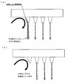
- the tip part of the outermost nozzle is most affected by this air flow, and the volatilization loss of platinum is accelerated by the air flow at this portion, and wear is caused (FIG. 1 (a)).
- Possible countermeasures for the outermost nozzles when wear accelerated by the airflow as described above occurs is to protect the nozzles by installing members such as windbreak walls around the nozzle group. It is possible to adjust the airflow around. However, adding an additional member such as a windbreak wall to the base plate may increase the weight of the entire bushing. Moreover, it is preferable to apply the same precious metal as that of the nozzle or the like as the material for the windproof wall exposed to a high temperature similarly to the nozzle and the base plate, and there is a concern about the material cost.
- the present inventors considered the cause of nozzle damage as described above, and decided to plug the outermost nozzle of the nozzle group that is likely to be damaged as a suitable countermeasure.
- a nozzle is a hollow cylinder and a member intended to circulate a fluid inside, and plugging this is to eliminate this function. Even if some nozzles are plugged, the number of glass fibers discharged from the bushing is reduced. However, in order for the nozzle to function properly, it is premised that no damage will occur, and fluid discharge from the damaged nozzle becomes unstable, which may affect the quality of the entire glass fiber produced. is there.
- the present inventors considered that the stability of spinning from the nozzles of the entire bushing should be given top priority, and decided to plug the nozzles at sites where wear and breakage are predicted.
- the present invention comprises a base plate and a plurality of nozzles for discharging molten glass, and in a bushing for glass fiber production formed by joining a nozzle group formed by arranging the plurality of nozzles to the pace plate,
- the nozzle constituting at least one nozzle row of the nozzle row which is the outermost layer of the nozzle group is plugged from the tip to a depth of 1/2 or more of the nozzle length, for producing glass fiber Is a bushing.
- the nozzles constituting the outermost layer row of the nozzle group are plugged with a hole having a certain length or more from the tip. This plugged nozzle does not discharge glass even if the tip is worn or damaged, and the entire bushing can spin glass fibers stably.
- the bushing plate for producing glass fiber according to the present invention plugs the outermost nozzles of the nozzles arranged in alignment. Therefore, other configurations such as the base plate are the same as those of the conventional bushing plate.
- the base plate is a member for retaining the molten glass substrate and has a plate shape or a box shape by bending.
- the base plate includes a through hole at a connection position with the nozzle.
- the material of the base plate is made of platinum or a platinum alloy.
- a platinum-rhodium alloy rhodium concentration: 5 to 20 wt%, a dispersion-type reinforced platinum alloy or a dispersion-type reinforced platinum-rhodium for the purpose of improving the strength. Alloy is applied.
- the one used in the conventional bushing plate for glass fiber production is applied.
- a plurality of nozzles are aligned and joined to the bottom surface of the base plate.
- the shape of the nozzle is not particularly limited, and may be a straight straight pipe or a tapered tapered cylinder. Further, platinum or the above-described platinum alloy is also applied to the nozzle material.
- the nozzle which comprises the nozzle row of the outermost layer is plugged from the front-end
- the plugging depth requires that a portion of 1 ⁇ 2 or more of the nozzle length is blocked. This is because if the plugging depth is too shallow, the nozzle in the process of use is worn and the hole penetrates and the molten glass is discharged.
- the plugged nozzle is plugged over the entire length of the nozzle and has no holes at both ends. This is because even if there is a hole in the nozzle base, it is not used for glass spinning, but molten glass flows into and remains in the hole, and it is necessary to remove it.
- a method of plugging the nozzle it may be plugged by inserting a wire or rod into the hole of a normal perforated nozzle, but from the beginning a solid cylinder without a hole is used. May be used.
- the number of nozzles installed in the bushing plate for glass fiber production is not particularly limited, but usually there are many having 200 to 8000 nozzles.
- the nozzle groups arranged at regular intervals may be arranged in a plurality of island shapes.
- the nozzles to be plugged may be set for the nozzle rows along the four sides of the base plate in each nozzle group.
- all nozzles may be arranged on the base plate at equal intervals to form a single nozzle group. In this case, it is preferable to plug the nozzles of the nozzle rows on the four sides of the nozzle group.
- the bushing plate for glass fiber production according to the present invention plugs a part of the nozzles with respect to the conventional bushing plate. Although this bushing cannot produce glass fiber from a plugged nozzle, since there are few changes compared to conventional bushings, production of stable glass fiber while suppressing production cost and weight increase It can be performed.
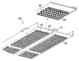
- FIG. 2 schematically shows a bushing plate 100 for producing glass fibers according to the present embodiment.
- the glass fiber manufacturing bushing plate includes a base plate 10 and a plurality of nozzles 20 aligned on the bottom surface thereof.
- the base plate 10 is formed by bending a platinum plate material (thickness 1.5 mm), and is formed by bending an end portion while providing a convex portion at the center (bottom dimension: 444 mm ⁇ 120 mm).
- the convex portion is formed in the center for rectification of the molten glass body flowing from above.
- the nozzle 20 is joined to the base plate 10 by forming four nozzle groups in an island shape. In each nozzle group, 20 ⁇ 20 nozzles are joined at intervals of 6.4 mm. The total number of nozzles joined to the base plate 10 is 1600.
- the nozzle 20 is a tapered cylindrical body having an outer shape of 2.94 mm (upper end outer diameter) ⁇ 2.35 mm (lower end outer diameter). All are made of platinum. Of the nozzles in each nozzle group, the nozzles 20 'constituting the outermost nozzle row along the four sides of the base plate are plugged. The other nozzles are normal nozzles having a through hole of ⁇ 1.65 mm.
- each nozzle As a manufacturing process of each nozzle, a solid cylinder formed in the above-described outer shape and dimensions is prepared, and the plugged nozzle 20 ′ is used as it is, and the normal nozzle 20 is perforated. After that, it was joined to the base plate 10.
- the nozzles 20 and 20 ′ are attached to the base plate 10 by previously drilling a 2.76 mm hole at each nozzle mounting position of the base plate 10, and after inserting the nozzles 20 and 20 ′, heating them in an electric furnace. Then, the base of the joint was welded from the upper surface of the base plate (the molten glass inflow surface) with a YAG laser.
- a terminal and a box side flange are joined to the above bushing plate to constitute a box type container.
- This bushing is incorporated into a glass manufacturing apparatus.
- the glass manufacturing apparatus includes a glass raw material melting tank prepared in a target composition, a molten glass clarification tank, and a stirring tank for stirring and homogenizing the clarified molten glass, and a bushing is installed downstream of these. .
- the glass fiber discharged from the bushing is wound up appropriately.
- glass fiber production was carried out for one year using a glass production apparatus equipped with the glass fiber production bushing plate according to the present embodiment shown in FIG. During this time, no noticeable abnormality was observed on the bushing plate, and the spinning of the glass fiber was stable. Then, after the operation of the apparatus for one year, the apparatus was shut down and the nozzle of the bushing plate was inspected. As a result, wear was observed at some nozzle tips of the plugged nozzle row, and the side surfaces of the nozzles were shaved within a range of about 1.5 mm from the tips. On the other hand, no abrasion was observed at all on the inner normal nozzle. It is considered that the outermost plugged nozzle was sacrificed to protect the inner nozzle group.
- the bushing plate for producing glass fibers according to the present invention suppresses abrasion damage of the nozzle group for spinning by plugging some nozzles.
- ADVANTAGE OF THE INVENTION According to this invention, stable operation in a long operation period can be enabled about a glass manufacturing apparatus, and a quality glass fiber can be manufactured efficiently.
Landscapes
- Engineering & Computer Science (AREA)
- Chemical & Material Sciences (AREA)
- Life Sciences & Earth Sciences (AREA)
- General Life Sciences & Earth Sciences (AREA)
- Geochemistry & Mineralogy (AREA)
- Manufacturing & Machinery (AREA)
- Materials Engineering (AREA)
- Organic Chemistry (AREA)
- Manufacture, Treatment Of Glass Fibers (AREA)
- Spinning Methods And Devices For Manufacturing Artificial Fibers (AREA)
Abstract
Priority Applications (5)
| Application Number | Priority Date | Filing Date | Title |
|---|---|---|---|
| EP15806308.1A EP3156379B1 (fr) | 2014-06-10 | 2015-06-08 | Douille de production de fibres de verre |
| CN201580030612.8A CN106458698A (zh) | 2014-06-10 | 2015-06-08 | 玻璃纤维制造用漏板 |
| MYPI2016704412A MY182114A (en) | 2014-06-10 | 2015-06-08 | Glass-fiber-production bushing |
| US15/314,205 US20170247283A1 (en) | 2014-06-10 | 2015-06-08 | Bushing for manufacturing glass fiber |
| KR1020167034288A KR101850238B1 (ko) | 2014-06-10 | 2015-06-08 | 유리 섬유 제조용 부싱 |
Applications Claiming Priority (2)
| Application Number | Priority Date | Filing Date | Title |
|---|---|---|---|
| JP2014-119430 | 2014-06-10 | ||
| JP2014119430A JP5795104B1 (ja) | 2014-06-10 | 2014-06-10 | ガラス繊維製造用ブッシング |
Publications (1)
| Publication Number | Publication Date |
|---|---|
| WO2015190425A1 true WO2015190425A1 (fr) | 2015-12-17 |
Family
ID=54330206
Family Applications (1)
| Application Number | Title | Priority Date | Filing Date |
|---|---|---|---|
| PCT/JP2015/066441 Ceased WO2015190425A1 (fr) | 2014-06-10 | 2015-06-08 | Douille de production de fibres de verre |
Country Status (8)
| Country | Link |
|---|---|
| US (1) | US20170247283A1 (fr) |
| EP (1) | EP3156379B1 (fr) |
| JP (1) | JP5795104B1 (fr) |
| KR (1) | KR101850238B1 (fr) |
| CN (1) | CN106458698A (fr) |
| MY (1) | MY182114A (fr) |
| TW (1) | TWI548602B (fr) |
| WO (1) | WO2015190425A1 (fr) |
Families Citing this family (5)
| Publication number | Priority date | Publication date | Assignee | Title |
|---|---|---|---|---|
| JP6445110B1 (ja) * | 2017-10-10 | 2018-12-26 | 田中貴金属工業株式会社 | ガラス繊維製造用のブッシングプレート |
| JP7207593B2 (ja) * | 2018-06-27 | 2023-01-18 | 日本電気硝子株式会社 | ブッシング、及びガラス繊維の製造方法 |
| JP6624750B1 (ja) * | 2018-09-07 | 2019-12-25 | 田中貴金属工業株式会社 | ガラス繊維製造用ブッシング |
| JP2020040850A (ja) * | 2018-09-07 | 2020-03-19 | 田中貴金属工業株式会社 | ガラス繊維製造用ブッシング |
| JP7639306B2 (ja) | 2020-11-19 | 2025-03-05 | 日本電気硝子株式会社 | ブッシング、及びガラス繊維の製造方法 |
Citations (3)
| Publication number | Priority date | Publication date | Assignee | Title |
|---|---|---|---|---|
| JPH0537931U (ja) * | 1991-10-29 | 1993-05-21 | 日本電気硝子株式会社 | ガラス繊維製造装置 |
| JPH09142871A (ja) * | 1995-11-24 | 1997-06-03 | Nippon Electric Glass Co Ltd | ガラス繊維製造装置 |
| JP2010502543A (ja) * | 2006-08-29 | 2010-01-28 | オーシーヴィー インテレクチュアル キャピタル リミテッド ライアビリティ カンパニー | 冷却支持フィンを備えたブッシング組立体 |
Family Cites Families (5)
| Publication number | Priority date | Publication date | Assignee | Title |
|---|---|---|---|---|
| US3607164A (en) * | 1969-08-18 | 1971-09-21 | Owens Corning Fiberglass Corp | Apparatus for producing glass filaments |
| US3955951A (en) * | 1975-06-02 | 1976-05-11 | Johns-Manville Corporation | Repairing clogged orifices in fiberizing bushings |
| US5928402A (en) * | 1997-08-04 | 1999-07-27 | Owens Corning Fiberglas Technology, Inc. | Multi-screen system for mixing glass flow in a glass bushing |
| US7980099B2 (en) * | 2007-03-15 | 2011-07-19 | Ocv Intellectual Capital, Llc | Multiple alloy bushing assembly |
| CN101423327A (zh) * | 2008-11-26 | 2009-05-06 | 中材科技股份有限公司 | 拉丝漏板的漏嘴 |
-
2014
- 2014-06-10 JP JP2014119430A patent/JP5795104B1/ja active Active
-
2015
- 2015-06-03 TW TW104117917A patent/TWI548602B/zh active
- 2015-06-08 EP EP15806308.1A patent/EP3156379B1/fr active Active
- 2015-06-08 MY MYPI2016704412A patent/MY182114A/en unknown
- 2015-06-08 CN CN201580030612.8A patent/CN106458698A/zh active Pending
- 2015-06-08 WO PCT/JP2015/066441 patent/WO2015190425A1/fr not_active Ceased
- 2015-06-08 US US15/314,205 patent/US20170247283A1/en not_active Abandoned
- 2015-06-08 KR KR1020167034288A patent/KR101850238B1/ko active Active
Patent Citations (3)
| Publication number | Priority date | Publication date | Assignee | Title |
|---|---|---|---|---|
| JPH0537931U (ja) * | 1991-10-29 | 1993-05-21 | 日本電気硝子株式会社 | ガラス繊維製造装置 |
| JPH09142871A (ja) * | 1995-11-24 | 1997-06-03 | Nippon Electric Glass Co Ltd | ガラス繊維製造装置 |
| JP2010502543A (ja) * | 2006-08-29 | 2010-01-28 | オーシーヴィー インテレクチュアル キャピタル リミテッド ライアビリティ カンパニー | 冷却支持フィンを備えたブッシング組立体 |
Non-Patent Citations (1)
| Title |
|---|
| See also references of EP3156379A4 * |
Also Published As
| Publication number | Publication date |
|---|---|
| EP3156379A4 (fr) | 2018-04-25 |
| EP3156379A1 (fr) | 2017-04-19 |
| JP2015231926A (ja) | 2015-12-24 |
| TWI548602B (zh) | 2016-09-11 |
| JP5795104B1 (ja) | 2015-10-14 |
| US20170247283A1 (en) | 2017-08-31 |
| CN106458698A (zh) | 2017-02-22 |
| EP3156379B1 (fr) | 2019-04-03 |
| MY182114A (en) | 2021-01-18 |
| KR101850238B1 (ko) | 2018-04-18 |
| TW201604160A (zh) | 2016-02-01 |
| KR20170007356A (ko) | 2017-01-18 |
Similar Documents
| Publication | Publication Date | Title |
|---|---|---|
| JP5795104B1 (ja) | ガラス繊維製造用ブッシング | |
| JP5813145B2 (ja) | ガラス繊維製造用ブッシング | |
| JP6445110B1 (ja) | ガラス繊維製造用のブッシングプレート | |
| US11384007B2 (en) | Bushing for producing glass fibers | |
| CN109694176A (zh) | 玻璃熔化炉以及玻璃物品的制造方法 | |
| JP2020040850A (ja) | ガラス繊維製造用ブッシング | |
| JP5689132B2 (ja) | 紡糸ノズル配列 | |
| US12054417B2 (en) | Bushing for producing glass fibers and method for producing glass fibers | |
| JP2020121913A (ja) | ガラス繊維製造用のブッシング | |
| Koch et al. | Design and manufacture of bushings for glass fibre production |
Legal Events
| Date | Code | Title | Description |
|---|---|---|---|
| 121 | Ep: the epo has been informed by wipo that ep was designated in this application |
Ref document number: 15806308 Country of ref document: EP Kind code of ref document: A1 |
|
| REEP | Request for entry into the european phase |
Ref document number: 2015806308 Country of ref document: EP |
|
| WWE | Wipo information: entry into national phase |
Ref document number: 2015806308 Country of ref document: EP |
|
| WWE | Wipo information: entry into national phase |
Ref document number: 15314205 Country of ref document: US |
|
| ENP | Entry into the national phase |
Ref document number: 20167034288 Country of ref document: KR Kind code of ref document: A |
|
| NENP | Non-entry into the national phase |
Ref country code: DE |