WO2015194256A1 - Roue de véhicule - Google Patents
Roue de véhicule Download PDFInfo
- Publication number
- WO2015194256A1 WO2015194256A1 PCT/JP2015/062277 JP2015062277W WO2015194256A1 WO 2015194256 A1 WO2015194256 A1 WO 2015194256A1 JP 2015062277 W JP2015062277 W JP 2015062277W WO 2015194256 A1 WO2015194256 A1 WO 2015194256A1
- Authority
- WO
- WIPO (PCT)
- Prior art keywords
- pad
- decoration
- vehicle wheel
- rim portion
- ink
- Prior art date
- Legal status (The legal status is an assumption and is not a legal conclusion. Google has not performed a legal analysis and makes no representation as to the accuracy of the status listed.)
- Ceased
Links
Images









Classifications
-
- B—PERFORMING OPERATIONS; TRANSPORTING
- B41—PRINTING; LINING MACHINES; TYPEWRITERS; STAMPS
- B41M—PRINTING, DUPLICATING, MARKING, OR COPYING PROCESSES; COLOUR PRINTING
- B41M1/00—Inking and printing with a printer's forme
- B41M1/26—Printing on other surfaces than ordinary paper
- B41M1/28—Printing on other surfaces than ordinary paper on metals
-
- B—PERFORMING OPERATIONS; TRANSPORTING
- B41—PRINTING; LINING MACHINES; TYPEWRITERS; STAMPS
- B41M—PRINTING, DUPLICATING, MARKING, OR COPYING PROCESSES; COLOUR PRINTING
- B41M5/00—Duplicating or marking methods; Sheet materials for use therein
- B41M5/0041—Digital printing on surfaces other than ordinary paper
- B41M5/0047—Digital printing on surfaces other than ordinary paper by ink-jet printing
-
- B—PERFORMING OPERATIONS; TRANSPORTING
- B41—PRINTING; LINING MACHINES; TYPEWRITERS; STAMPS
- B41M—PRINTING, DUPLICATING, MARKING, OR COPYING PROCESSES; COLOUR PRINTING
- B41M5/00—Duplicating or marking methods; Sheet materials for use therein
- B41M5/0041—Digital printing on surfaces other than ordinary paper
- B41M5/0058—Digital printing on surfaces other than ordinary paper on metals and oxidised metal surfaces
-
- B—PERFORMING OPERATIONS; TRANSPORTING
- B41—PRINTING; LINING MACHINES; TYPEWRITERS; STAMPS
- B41M—PRINTING, DUPLICATING, MARKING, OR COPYING PROCESSES; COLOUR PRINTING
- B41M5/00—Duplicating or marking methods; Sheet materials for use therein
- B41M5/26—Thermography ; Marking by high energetic means, e.g. laser otherwise than by burning, and characterised by the material used
- B41M5/382—Contact thermal transfer or sublimation processes
- B41M5/38207—Contact thermal transfer or sublimation processes characterised by aspects not provided for in groups B41M5/385 - B41M5/395
-
- B—PERFORMING OPERATIONS; TRANSPORTING
- B60—VEHICLES IN GENERAL
- B60B—VEHICLE WHEELS; CASTORS; AXLES FOR WHEELS OR CASTORS; INCREASING WHEEL ADHESION
- B60B7/00—Wheel cover discs, rings, or the like, for ornamenting, protecting, venting, or obscuring, wholly or in part, the wheel body, rim, hub, or tyre sidewall, e.g. wheel cover discs, wheel cover discs with cooling fins
- B60B7/0026—Wheel cover discs, rings, or the like, for ornamenting, protecting, venting, or obscuring, wholly or in part, the wheel body, rim, hub, or tyre sidewall, e.g. wheel cover discs, wheel cover discs with cooling fins characterised by the surface
- B60B7/0033—Wheel cover discs, rings, or the like, for ornamenting, protecting, venting, or obscuring, wholly or in part, the wheel body, rim, hub, or tyre sidewall, e.g. wheel cover discs, wheel cover discs with cooling fins characterised by the surface the dominant aspect being the surface appearance
- B60B7/0053—Wheel cover discs, rings, or the like, for ornamenting, protecting, venting, or obscuring, wholly or in part, the wheel body, rim, hub, or tyre sidewall, e.g. wheel cover discs, wheel cover discs with cooling fins characterised by the surface the dominant aspect being the surface appearance the surface being decorated
-
- B—PERFORMING OPERATIONS; TRANSPORTING
- B41—PRINTING; LINING MACHINES; TYPEWRITERS; STAMPS
- B41M—PRINTING, DUPLICATING, MARKING, OR COPYING PROCESSES; COLOUR PRINTING
- B41M2205/00—Printing methods or features related to printing methods; Location or type of the layers
- B41M2205/38—Intermediate layers; Layers between substrate and imaging layer
-
- B—PERFORMING OPERATIONS; TRANSPORTING
- B41—PRINTING; LINING MACHINES; TYPEWRITERS; STAMPS
- B41M—PRINTING, DUPLICATING, MARKING, OR COPYING PROCESSES; COLOUR PRINTING
- B41M2205/00—Printing methods or features related to printing methods; Location or type of the layers
- B41M2205/42—Multiple imaging layers
Definitions
- the present invention relates to a vehicle wheel.
- the range to be decorated when decorating the rim of a vehicle wheel, the range to be decorated is relatively long. Conventionally, when the range to decorate is comparatively long, it decorates by painting or sticking a sticker. With these decoration techniques, a uniform decoration state is obtained over the longitudinal direction of the decoration range.
- Patent Document 1 discloses that a decorative pattern groove is formed in a rim portion of a vehicle wheel and paint is filled in the groove.
- Patent Document 2 discloses that a plurality of arc-shaped seals are attached to a rim portion of a vehicle wheel so that the overall shape is a ring shape.
- Patent Document 1 when painting a groove, if the pattern to be decorated is a line, it is easy to form and paint the groove, but it is difficult to form and paint the groove if it is a complicated pattern such as letters. Become. Therefore, the decoration by painting like patent document 1 has a restriction
- An object of the present invention is to provide a vehicle wheel having a decorated rim portion that can be manufactured while maintaining high productivity even if the degree of freedom in decoration is high.
- the vehicle wheel according to the present invention is a vehicle wheel having an annular rim portion, a hub portion arranged inside the rim portion, and a spoke portion connecting the rim portion and the hub portion,
- the rim portion is formed by directly adhering ink to the decorative surface of the rim portion, and has a pattern in which the length in the direction orthogonal to the circumferential direction of the rim portion is not constant, and the rim portion
- a second decoration that is formed by directly adhering ink to the decorative surface of the part, is arranged in the circumferential direction of the first decorative part and the rim part, and has the same pattern as the first decorative part Part.
- the vehicle wheel of the present invention having an annular rim portion, a hub portion disposed inside the rim portion, and a spoke portion connecting the rim portion and the hub portion is provided with a first decoration on the decorative surface of the rim portion.
- the part and the 2nd decoration part are formed.
- the first decorative portion is formed by directly attaching ink to the decorative surface of the rim portion, and has a pattern in which the length in the direction orthogonal to the circumferential direction of the rim portion is not constant.
- the second decorating part is formed by directly attaching ink to the decorating surface of the rim part, arranged in the circumferential direction of the first decorating part and the rim part, and has the same pattern as the first decorating part. Have. Ink is directly attached to the first decorative portion and the second decorative portion.
- the 1st decoration part and the 2nd decoration part are formed by printing.
- Printing includes plate printing and non-plate printing.
- Plate printing includes screen printing and pad printing.
- ink is transferred from a plate (corresponding to a pad in the case of pad printing) to an object to be printed.
- Plateless printing includes electrostatic copying (copier), fusion / sublimation thermal transfer (thermal printer), and ink jet printing.
- the first decorative portion and the second decorative portion have a pattern in which the length in the direction orthogonal to the circumferential direction of the rim portion is not constant. Such a pattern may not be decorated by painting on a groove for decoration, painting using masking, or sticking a seal. Even if it is possible, it takes time and productivity decreases.
- the 1st decoration part and the 2nd decoration part of this invention are formed by printing, it can improve a decoration freedom degree and productivity.
- the first decorative portion and the second decorative portion are separated from each other in the circumferential direction of the rim portion.
- the circumferential end of the rim portion of the first decorative portion and the circumferential end of the rim portion of the second decorative portion are separated from each other. Therefore, compared with the case where the position of the end part of the 1st decoration part and the end part of the 2nd decoration part is the same, when the 1st decoration part and the 2nd decoration part have overlapped, The printing misalignment of the first decorative portion and the second decorative portion is not noticeable. Therefore, even if the 1st decoration part or the 2nd decoration part has shifted
- an end portion of the first decoration portion in the circumferential direction of the rim portion extends obliquely with respect to a direction orthogonal to the circumferential direction of the rim portion.
- the circumferential end of the rim portion of the first decorative portion is a rim. If it is orthogonal to the circumferential direction of the portion, the ink forming the end portion tends to remain on the outer peripheral surface of the pad.
- limb part of a 1st decoration part is extended diagonally with respect to the direction orthogonal to the circumferential direction of a rim
- the first decorative portion includes a first pattern including an end portion in the circumferential direction of the rim portion of the first decorative portion, and a circumferential direction of the first pattern and the rim portion. And a second pattern separated from each other.
- the 1st decoration part is the 1st pattern including the edge part of the circumferential direction of the rim
- the opposing end portions of the first pattern and the second pattern of the first decoration portion extend obliquely with respect to a direction orthogonal to the circumferential direction of the rim portion. Is preferred.
- the opposing end portions of the first pattern and the second pattern are rim portions.
- the ink forming the end tends to remain on the outer peripheral surface of the pad.
- the opposite end portions of the first pattern and the second pattern extend obliquely with respect to the direction orthogonal to the circumferential direction of the rim portion, the ink forming the end portion
- the color of the first decorative portion and the color of the second decorative portion are the same.
- the rim portion is formed by directly attaching ink to the decoration surface of the rim portion, and includes the first decoration portion, the second decoration portion, and the rim portion. It is preferable to have the 3rd decoration part which has located in the circumferential direction and has the same pattern as the said 1st decoration part.
- the rim portion is formed by directly attaching ink to the decoration surface of the rim portion, and includes the first decoration portion, the second decoration portion, and the rim portion. It is preferable to have the 4th decoration part which has located in the circumferential direction and has a pattern different from the said 1st decoration part.
- the fourth decorative portion has a color different from that of at least one of the first decorative portion and the second decorative portion.
- the vehicle wheel of the present invention is preferably a saddle type vehicle wheel.
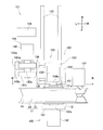
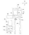
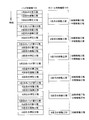
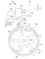
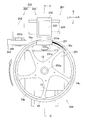
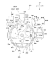
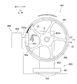
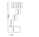
- FIG. 4 is a cross-sectional view taken along line AA in FIG. 3. It is a figure which shows a part of process of decorating a vehicle wheel with the decorating apparatus of FIG. It is a figure which shows the relationship between a part of process of decorating a vehicle wheel with the decorating apparatus of FIG. 3, and time. It is a figure which shows the relationship between a part of process of decorating a vehicle wheel with the decorating apparatus of FIG. 3, and time.
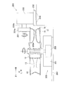
- FIG. 13 is a sectional view taken along line BB in FIG. 12. It is a partial top view of the decorating device of FIG.
- FIG. 1 It is CC sectional view taken on the line of FIG. It is a figure which shows the relationship between the process and time which decorate a vehicle wheel with the decorating apparatus of FIG. It is a side view of the decoration wheel for vehicles (wheel for vehicles) of a 4th embodiment. It is a top view of the decoration apparatus which decorated the decoration wheel for vehicles of 4th Embodiment, Comprising: It is a figure which shows the state which is performing decoration. It is a figure which shows the relationship between the process and time which decorate a vehicle wheel with the decorating apparatus of FIG. It is a side view of the decoration wheel for vehicles (vehicle wheel) of 5th Embodiment. It is a top view of the decorating apparatus which decorated the decorating wheel for vehicles of 5th Embodiment.
- FIG. 26 It is a top view of the decorating apparatus of FIG. 26, Comprising: It is a figure which shows the state which is decorating. It is the DD sectional view taken on the line of FIG. It is a figure which shows the relationship between the process and time which decorate a vehicle wheel with the decorating apparatus of FIG.
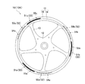
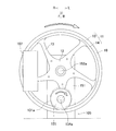
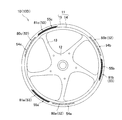
- FIG. 1 shows a vehicle wheel 10A (hereinafter referred to as a vehicle decoration wheel 10A) of the present embodiment decorated by a decoration device 1 described later.
- the decoration device 1 decorates the vehicle wheel 10 by pad printing. That is, the vehicle decoration wheel 10A is decorated by pad printing.
- the vehicle wheel 10 that is to be decorated will be described.
- the vehicle wheel 10 includes an annular rim portion 11, a hub portion 12 disposed inside the rim portion 11, and a spoke portion 13 that connects the rim portion 11 and the hub portion 12.
- the hub portion 12 is inserted with an axle of a motorcycle.
- a tire is attached to the rim portion 11.
- the rim portion 11 includes a bottom wall portion 14 formed in a substantially cylindrical shape, and two side wall portions 15 extending radially outward from both ends of the bottom wall portion 14 in the axle direction.
- the outer surface of the side wall portion 15 (the surface far from the other side wall portion 15) is formed substantially parallel to a direction orthogonal to the central axis of the rim portion 11.
- An axial end portion of the inner peripheral surface of the bottom wall portion 14 is formed substantially parallel to the central axis of the rim portion 11.
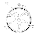
- Decorative portions 50a to 50c and 51a to 51c arranged in the circumferential direction are formed on the outer surface of the side wall portion 15 of the rim portion 11 of the vehicle decoration wheel 10A.
- the positions where the decoration portions 50a to 50c of the rim portion 11 of the vehicle wheel 10 are formed are referred to as decoration positions 54a to 54c.
- the positions where the decoration portions 51a to 51c of the rim portion 11 of the vehicle wheel 10 are formed are referred to as decoration positions 55a to 55c.
- the entire circumferential direction of the outer surface of the side wall portion 15 of the rim portion 11 of the vehicle wheel 10 corresponds to the decorative surface of the present invention.
- the decoration portions 50a to 50c are composed of characters 52.
- the decorative portions 50a to 50c are arranged at a pitch of 120 °.
- the decoration portions 50a to 50c are arranged with a space in the circumferential direction of the rim portion 11.
- the decorating parts 51 a to 51 c are configured by a line 53.
- the decorating parts 51a to 51c are arranged at a 120 ° pitch at positions that do not overlap the decorating parts 50a to 50c.
- the decorating parts 51a to 51c are arranged at intervals in the circumferential direction of the rim part 11.
- the circumferential lengths of the decoration portions 50a to 50c are substantially the same as the circumferential lengths of the decoration portions 51a to 51c.
- the circumferential lengths of the decorative portions 50a to 50c and 51a to 51c are lengths corresponding to an angle range of about 30 ° of the side wall portion 15 of the rim portion 11, but are not limited thereto. It is not a thing.
- the lengths of the decorative portions 50a to 50c formed by the characters 52 are not constant in the radial direction (direction orthogonal to the circumferential direction). Further, both circumferential ends of the decorative portions 51a to 51c (line 53) are inclined with respect to the radial direction of the rim portion 11 (direction perpendicular to the circumferential direction of the rim portion 11). Thereby, in the circumferential direction of the rim part 11, the lengths of the decoration parts 51a to 51c (line 53) in the radial direction (direction orthogonal to the circumferential direction) are not constant.
- the vehicle wheel 10 is black.
- the decorative portions 50a to 50c and 51a to 51c are different colors from both white and black.
- the decoration portions 50a to 50c are the same color as each other, and the decoration portions 51a to 51c are the same color as each other.
- the decoration portions 50a to 50c and the decoration portions 51a to 51c are different colors, but may be the same color.
- the decoration units 50a to 50c correspond to the first decoration unit, the second decoration unit, and the third decoration unit of the present invention. The same can be said for the decorative portions 51a to 51c. Further, when any one of the decorating parts 50a to 50c corresponds to the first decorating part, any of the decorating parts 51a to 51c corresponds to the fourth decorating part of the present invention.
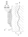
- FIG. 2 is a diagram schematically showing a cross section of the vehicle decorative wheel 10A.
- the vehicle wheel 10 includes a wheel body 40 and a paint layer 41 formed on the surface of the wheel body 40. That is, the decorative surface of the rim portion 11 is formed by the paint layer 41.
- the wheel body 40 is formed by casting.
- the wheel main body 40 has the chemical conversion treatment film 40a formed in the surface by chemical conversion treatment.
- the wheel body 40 in a state before the chemical conversion treatment is referred to as an untreated wheel body.
- the untreated wheel body is casted using, for example, an aluminum alloy, a magnesium alloy, or the like.
- the casting method is not particularly limited, and examples thereof include die casting, gravity casting, and sand casting.
- the surface of the untreated wheel body taken out from the mold is formed with irregularities due to solidification shrinkage during casting.
- the unevenness formed by solidification shrinkage is small (gradual) compared to gravity casting and sand casting.
- irregularities having an arithmetic average roughness Ra of, for example, about 0.2 to 5.0 ⁇ m are formed on at least a part of the surface of the untreated wheel body.
- This untreated wheel main body is immersed in a zirconium-based chemical conversion treatment solution, for example, and subjected to chemical conversion treatment. Thereby, a chemical reaction occurs on the surface of the untreated wheel body, and the chemical conversion film 40a is formed.
- the thickness of the chemical conversion treatment film 40a is very small compared to the depth of the concave portion (height of the convex portion) formed on at least a part of the surface of the untreated wheel body. Therefore, unevenness (concave part 42 and convex part 43) is formed on at least a part of the wheel main body 40 on which the chemical conversion treatment film 40a is formed, similarly to the surface of the untreated wheel main body.
- the surface of the wheel body 40 is decorated in the region where the irregularities (the concave portions 42 and the convex portions 43) are formed. Further, the surface of the wheel body 40 (the surface of the chemical conversion treatment film 40a) is finely roughened (uneven) by the chemical conversion treatment.
- the paint layer 41 is formed by painting.
- the paint layer 41 is formed on the entire surface of the wheel body 40.
- the paint layer 41 is formed of a paint such as an epoxy paint, an acrylic paint, or a melamine paint, for example.
- the paint layer 41 may be formed by only one coating, or may be formed by applying two or more times with the same or different types of coating. At least the surface layer of the paint layer 41 is formed of a black paint.
- the paint layer 41 is in contact with not only the convex portion 43 on the surface of the wheel body 40 but also the concave portion 42. Further, since the paint layer 41 is formed by painting, the surface of the paint layer 41 is formed with unevenness that is gentler than the unevenness (concave part 42 and convex part 43) of the surface of the wheel body 40. Since the unevenness is gentle, it is possible to ensure adhesion with the decorative portions 50a to 50c and 51a to 51c. Rather, the contact area between the paint layer 41 and the decorative portions 50a to 50c and 51a to 51c can be increased by the unevenness, and the adhesion between the paint layer 41 and the decorative portions 50a to 50c and 51a to 51c can be improved.
- the paint layer 41 is formed by spray coating such as electrostatic coating or air spray coating. In spray painting, paint is sprayed as particles such as fine droplets. Therefore, a plurality of fine granular protrusions 44 are formed on the surface of the paint layer 41.
- the protrusion 44 can increase the contact area between the paint layer 41 and the decorative portions 50a to 50c and 51a to 51c, thereby improving the adhesion between the paint layer 41 and the decorative portions 50a to 50c and 51a to 51c.
- the decorative portions 50a to 50c and 51a to 51c are formed on the surface of the paint layer 41.
- the decorative portions 50a to 50c and 51a to 51c are formed of an ink such as polyurethane ink, acrylic ink, epoxy ink, or polyester ink.
- the decorative portions 50a to 50c and 51a to 51c have a structure in which a color ink layer 46 (color ink layer 46) is superimposed on a white ink layer 45 (white ink layer 45). This is because when only the color ink is superimposed on the black paint layer 41, the color of the ink is poor.
- the color ink layer 46 covers the entire surface of the white ink layer 45.
- the color ink layer 46 is in contact with the surface of the white ink layer 45 and a part of the surface of the paint layer 41. Thereby, it is possible to prevent the white ink from being exposed to the outside.
- Each of the white ink layer 45 and the color ink layer 46 of the present embodiment has a three-layer structure.
- the white ink layer 45 includes first to third white ink layers 45a to 45c.
- the color ink layer 46 includes first to third color ink layers 46a to 46c.
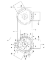
- the decoration device 1 includes four pad printing machines 2A to 2D, a fixed base 3 to which the vehicle wheel 10 is fixed, a rotary drive unit 4 that rotates the fixed base 3, and a rotary drive.
- the horizontal drive part 5 which horizontally moves the part 4 and the fixing stand 3, the drying apparatus 6, the receiving plate 7, and a control part (illustration omitted) etc. are provided.
- the rotation drive unit 4 is installed on the horizontal drive unit 5, and the fixed base 3 is installed on the rotation drive unit 4.
- illustration of the drying apparatus 6 is abbreviate
- the fixed base 3 includes a pedestal 31 installed on the rotation drive unit 4, and a plurality of support members 32, a center positioning member 33, and a circumferential direction positioning member 34 provided on the upper surface of the pedestal 31.
- the pedestal 31 is a disk-shaped member arranged horizontally.
- the pedestal 31 is fixed to a rotation shaft (not shown) extending in the vertical direction of the rotation drive unit 4 and is rotationally driven by the rotation drive unit 4.
- the plurality of support members 32 are arranged in the circumferential direction around the rotation center of the base 31.
- the side wall portion 15 of the rim portion 11 of the vehicle wheel 10 is placed on the upper surfaces of the plurality of support members 32.
- the center positioning member 33 extends in the vertical direction from the position of the rotation center of the base 31.
- the center positioning member 33 is inserted through the hub portion 12 of the vehicle wheel 10. As a result, the center of the vehicle wheel 10 is positioned with respect to the pedestal 31.
- the circumferential positioning member 34 is a columnar member, and extends upward from a position closer to the center positioning member 33 than the support member 32 of the pedestal 31. Positioning of the vehicle wheel 10 in the circumferential direction is performed with respect to the pedestal 31 by bringing the spoke portion 13 into contact with the circumferential positioning member 34.
- a plurality of receiving plate installation members 35 for installing the receiving plate 7 are provided on the upper surface of the base 31.
- the plurality of receiving plate installation members 35 are arranged at positions closer to the center positioning member 33 than the support member 32.
- the receiving plate installation member 35 includes a receiving plate support bar 35a extending upward from the upper surface of the base 31 and a pin 35b extending upward from the upper surface of the receiving plate support bar 35a.
- the diameter of the pin 35b is smaller than the diameter of the receiving plate support bar 35a.
- the receiving plate 7 is a donut-shaped plate member.
- the outer diameter of the backing plate 7 is slightly smaller than the inner diameter of the side wall portion 15 of the rim portion 11.
- the receiving plate 7 has a plurality of through holes.
- the receiving plate 7 is placed on the upper surface of the receiving plate support bar 35a in a state where the plurality of pins 35b of the receiving plate installation member 35 are inserted through the plurality of through holes of the receiving plate 7, respectively. Thereby, the upper surface of the receiving plate 7 is disposed at a position slightly lower than the outer surface of the side wall portion 15 of the rim portion 11.
- a hub portion 12 is disposed inside the central hole of the receiving plate 7.
- the receiving plate 7 presses a pad 24 (described later) against the side wall 15 of the rim portion 11, the receiving plate 7 is brought into contact with the receiving plate 7 so that the pad 24 is displaced in the radial direction of the vehicle wheel 10. It is for preventing.
- the rotation drive unit 4 has a rotation shaft (not shown) fixed to the fixed base 3 as described above.
- the rotation drive unit 4 rotates the fixed base 3 by rotating the rotation shaft with a drive source (not shown).
- the rotation drive unit 4 can rotate the fixed base 3 in both forward and reverse directions.
- the specific configuration of the drive source (not shown) of the rotation drive unit 4 is not particularly limited.
- the rotating shaft may be rotated by a motor.
- the horizontal drive unit 5 reciprocates the rotation drive unit 4 and the fixed base 3 in the horizontal direction between a first printing position indicated by a solid line in FIG. 3 and a second printing position indicated by a two-dot chain line in FIG.
- a specific configuration for moving the rotation driving unit 4 of the horizontal driving unit 5 is not particularly limited.
- two pad printing machines 2A and 2B are arranged side by side in the rotation direction of the fixed base 3 by the rotation driving unit 4 arranged at the first printing position.
- the remaining two pad printing machines 2C and 2D are arranged side by side in the rotation direction of the fixed base 3 by the rotation driving unit 4 arranged at the second printing position. More specifically, the pad printing machines 2A and 2B are arranged at positions shifted by 120 ° around the rotation center of the fixed base 3 by the rotation driving unit 4 arranged at the first printing position. Similarly, the pad printers 2C and 2D are arranged at positions shifted by 120 °.
- the pad printing machines 2A and 2B are for forming the decorative portions 50a to 50c of the characters 52 on the outer surface (decorative region, decorative surface) of the side wall portion 15 of the rim portion 11 of the vehicle wheel 10. .
- the pad printer 2A prints the characters 52 with white ink
- the pad printer 2B prints the characters 52 with color ink.
- the pad printing machines 2C and 2D are for forming the decorative portions 51a to 51c of the line 53 on the rim portion 11 of the vehicle wheel 10.
- the pad printer 2C prints the line 53 with white ink
- the pad printer 2D prints the line 53 with color ink.
- the pad printing machines 2A to 2D include a plate plate 21, an ink application unit 22 that applies ink to the plate plate 21, an ink application unit moving unit 23 that moves the ink application unit 22, and a pad. 24, pad moving means 25 for moving the pad 24, drying means 26, 27, and the like.
- the printing plate 21 is an intaglio plate having a character 52 or a line 53 groove formed on the upper surface thereof.
- the ink application part 22 is disposed above the plate 21.
- the ink application part moving means 23 reciprocates the ink application part 22 in the horizontal direction.
- the ink application unit 22 supplies ink onto the plate 21 when moving on the plate 21 in a predetermined direction, and scrapes off excess ink protruding from the groove of the plate 21 when moving in the opposite direction. .
- the pad moving means 25 has a pad fixing jig 25a for attaching the pad 24.
- the pad 24 is detachably fixed to the lower end portion of the pad fixing jig 25a.
- the pad moving means 25 reciprocates the pad 24 between the plate plate 21 and the rim portion 11 of the vehicle wheel 10 in the horizontal direction, and the pad 24 above the plate plate 21 and the rim portion 11 of the vehicle wheel 10. Is moved up and down. The pad 24 is pressed vertically downward against the plate plate 21 and the rim portion 11.
- the pad 24 is formed of an elastically deformable material such as silicon rubber or urethane.
- the pad 24 is formed in an arc shape having substantially the same curvature as the side wall portion 15 of the rim portion 11 when viewed from the vertical direction.
- the lower surface 24 a of the pad 24 is formed in an arc shape in a cross section orthogonal to the circumferential direction of the rim portion 11.
- the circumferential length of the pad 24 is slightly longer than the circumferential length of the character 52 or the line 53.
- the ink on the plate 21 is transferred to the lower surface 24a of the pad 24.
- the ink attached to the lower surface 24 a of the pad 24 is retransferred to the rim portion 11, and characters are transferred to the rim portion 11. 52 or line 53 is printed.
- the drying means 26 blows air to the lower surface 24a of the pad 24 to dry the ink attached to the lower surface 24a of the pad 24 when moving the pad 24 in the horizontal direction from the plate plate 21 toward the rim portion 11.
- the drying means 26 blows air to the lower surface 24a of the pad 24 to dry the ink attached to the lower surface 24a of the pad 24 when moving the pad 24 in the horizontal direction from the plate plate 21 toward the rim portion 11.
- the drying means 27 presses the pad 24 to which the ink has been applied against the rim portion 11 to release the pad 24, and then blows air to the portion of the rim portion 11 to which the ink has adhered, thereby drying the ink that has adhered to the rim portion 11. .
- the decorating device 1 overprints the same color ink to improve weather resistance and aesthetics. Therefore, after the ink transferred to the rim portion 11 is dried to some extent by the drying means 27, the ink is superimposed on the ink 52 to prevent the outline of the character 52 or the line 53 from blurring or collapsing.
- the pad printers 2A to 2D include a pad cleaning unit (not shown) that removes ink remaining on the lower surface 24a of the pad 24 after transferring the ink to the rim unit 11.
- the pad cleaning unit performs cleaning each time ink is transferred from the pad 24 to the rim unit 11 once to several times.
- the drying device 6 moves the rotation drive unit 4, the fixed base 3, and the vehicle wheel 10 from the first printing position to the second printing position by the horizontal driving unit 5, the side wall portion of the rim portion 11 of the vehicle wheel 10. 15 is blown with air.
- the drying device 6 is configured to be able to blow air over the entire outer surface of the side wall 15 of the rim 11, and the ink of the three decorative portions 50a to 50c formed by the pad printers 2A and 2B is used. dry.
- the vehicle wheel 10 is decorated at the second printing position by drying the ink of the decorating parts 50a to 50c to some extent by the drying device 6, the pad 24 of the pad printing machine 2C, 2D is decorated with the decorating parts 50a to 50c. It is possible to prevent the decorative portions 50a to 50c from being deformed even if they are in contact with a part of them.
- the control unit (not shown) controls the operations of the pad printing machines 2A to 2D, the rotation driving unit 4, the horizontal driving unit 5, and the drying device 6.
- the control unit includes a CPU (Central Processing Unit), a ROM (Read Only Memory), a RAM (Random Access Memory), and the like.
- the control unit causes the CPU to execute various processes according to data and programs stored in the RAM and ROM, and decorates the outer surface of the side wall portion 15 of the rim portion 11 of the vehicle wheel 10 with the decoration portions 50a to 50c, 51a to 51c is formed.
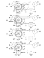
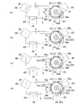
- FIGS. 5A to 5D and FIGS. 8A to 8D the white character 52 or line 53 is displayed in an arcuate frame, and the color character 52 or line 53 is arcuate. Shown in bold lines.
- the rotation driving unit 4 and the fixing base 3 are arranged at an intermediate position between the first printing position and the second printing position.
- the vehicle wheel 10 is fixed to the fixed base 3 (fixing step).
- the receiving plate 7 is attached to the fixed base 3.
- the horizontal driving unit 5 moves the rotation driving unit 4, the fixing base 3, and the vehicle wheel 10 to the first printing position.
- the pad 24 is moved horizontally, and the position above the rim portion 11 of the vehicle wheel 10 at the first printing position (hereinafter referred to as printing preparation). Position).
- the pad 24 of the pad printing machine 2 ⁇ / b> A is moved downward from the print preparation position, and the lower surface 24 a (transfer surface) of the pad 24 is decorated on the outer surface of the side wall portion 15 of the rim portion 11 of the vehicle wheel 10.
- the character 52 is printed with white ink on the decoration position 54 a of the rim portion 11.
- the process of moving the pad 24 from the position in contact with the plate plate 21 until the lower surface 24a of the pad 24 is brought into contact with the decoration position 54a of the outer surface (decorative surface) of the side wall portion 15 of the rim portion 11 is performed. Let it be a process. In the contact process, the pad 24 is not elastically deformed. Further, from the state in which the lower surface 24a of the pad 24 is brought into contact with the decoration position 54a of the rim portion 11 in the contact step, the pad fixing jig 25a is further moved toward the decoration position 54a, and the lower surface 24a of the pad 24 is moved.
- the process of pressing the rim part 11 to decorate the decoration position 54a of the rim part 11 is defined as a pressing process.
- the pad 24 is elastically deformed.
- the definition of the above-mentioned contact process and a press process is not limited to decorating the decoration position 54a, It is applied also when decorating the decoration positions 54b, 54c, 55a, and 55b. .
- the pressing process in the embodiment of Japanese Patent Application No. 2014-123695 which is the basic application of the present application is a process including a part of the contacting process and a pressing process in the present specification.
- the pressing step in the embodiment of Japanese Patent Application No. 2014-123695 is a step of pressing the pad 24 against the rim portion 11 by moving the pad 24 downward from the printing preparation position.
- the pad printing machine 2 ⁇ / b> A applies the ink to the plate plate 21 after separating the pad 24 from the plate plate 21.
- the pad 24 is moved away from the rim portion 11 to the position of the plate 21.
- the process of moving the pad 24 from the position in contact with the rim portion 11 to the position of the plate 21 is referred to as a pad returning process.
- the pad 24 is pressed against the plate 21 to which the ink has been applied, and the ink is attached to the lower surface 24a of the pad 24 (second attaching step).
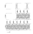
- the pad 24 is moved downward to bring the lower surface 24a of the pad 24 into contact with the decoration position 54a (second contact process). Subsequently, the lower surface 24a of the pad 24 is pressed against the decoration position 54a, and printing is performed with white ink on the decoration position 54a (second pressing step). As shown in FIG. 6, after the second pressing step, a second pad returning step, a third attaching step, a third contacting step, and a third pressing step are sequentially performed. In this way, white ink is overprinted three times at the decoration position 54a, and the white character 52 is printed at the decoration position 54a.
- the process which combined the adhesion process and the process which moves the pad 24 from the position which contacted the plate 21 to the printing preparation position is set as the printing preparation process. That is, the printing preparation process is a process including an adhesion process and a part of the contact process. Further, the second and subsequent printing preparation steps include a pad return step.
- the definition of the print preparation process is the same as the definition of the print preparation process in the embodiment of Japanese Patent Application No. 2014-123695 which is the basic application of the present application.
- the fourth adhesion step and the fourth contact step by the pad printer 2A are performed, and at the same time, the first adhesion step and the first contact step by the pad printer 2B. I do.
- the third pressing step by the pad printing machine 2A as shown in FIG. 5 (b)
- the rotary base 4 and the vehicle The wheel 10 is rotated by 120 ° (first movement step). That is, the vehicle wheel 10 moves relative to the pad printing machines 2A and 2B in the circumferential direction on a plane (horizontal plane) orthogonal to the pressing direction (vertically downward) of the pad 24.
- the vehicle wheel 10 moves relative to the position of the pad 24 when pressed against the rim portion 11 in the circumferential direction of the outer surface of the side wall portion 15 (longitudinal direction of the decorative surface).
- the movement distance of the rim part 11 is a circumferential distance between the circumferential center of the decoration position 54a and the circumferential center of the decoration position 54b.
- the moving process is performed simultaneously with at least one of the pad returning process, the attaching process, and the contacting process. This is because the working time can be shortened. As shown in FIG. 6, when the moving process is completed before the contact process is completed, it is preferable to drive the drying means 27 of the pad printing machine 2B to dry the ink printed on the rim portion 11. In this embodiment, the moving process is performed simultaneously with a part of the pad returning process and a part of the attaching process.
- a fourth contact step and a fourth pressing step by the pad printer 2A are performed, and a first contact step and a first pressing step by the pad printer 2B are performed.
- the pad printer 2A prints the character 52 with the white ink at the decoration position 54b of the rim portion 11.
- the pad printer 2B prints the characters 52 with color ink on the portion (decoration position 54a) printed with the white ink by the pad printer 2A.
- the timing of pressing the pad 24 of the pad printer 2A against the rim portion 11 and the timing of pressing the pad 24 of the pad printer 2B against the rim portion 11 are the same.
- the pad printing machine 2A and the pad printing machine 2B repeat a series of processes including a pad return process, an adhesion process, a contact process, and a pressing process twice.
- the decoration part 50a (color character 52) is formed in the decoration position 54a, and the white character 52 is printed in the decoration position 54b.
- the sixth pressing step by the pad printer 2A that is, after the third pressing step by the pad printer 2B
- the sixth pad returning step and the seventh attaching step by the pad printer 2A are performed simultaneously.
- a third pad returning step and a fourth attaching step are performed by the pad printer 2B.
- the sixth pressing step by the pad printing machine 2A as shown in FIG. 5 (c)
- the vehicle wheel 10 fixed to the fixed base 3, the rotary base 4 and the vehicle The wheel 10 is rotated by 120 ° (second movement process). Similar to the first movement process, at least a part of the second movement process is performed simultaneously with the pad returning process and the attaching process.
- the pad printing machine 2A and the pad printing machine 2B repeat a series of processes including a pad return process, an adhesion process, a contact process, and a pressing process twice.
- the decoration part 50b (color character 52) is formed in the decoration position 54b, and the white character 52 is printed in the decoration position 54c.
- a seventh contact process and a seventh pressing process by the pad printer 2B are performed. Thereafter, the pad printing machine 2B repeats a series of processes including a pad returning process, an attaching process, a contacting process, and a pressing process twice. Thereby, the decoration part 50c is formed in the decoration position 54c of a rim
- each pad 24 of the pad printing machine 2A, 2B has a range longer than the maximum length of each pad 24 of the rim portion 11 of the vehicle wheel 10 (the length of the line segment connecting both ends in the circumferential direction). Decorate.
- the range decorated by each pad 24 is longer than the circumferential length of the pad 24 (rotation direction by the rotation drive unit 4). Specifically, the range decorated by each pad 24 is approximately three times the circumferential length of the pad 24.
- the horizontal driving unit 5 moves the rotation driving unit 4, the fixing base 3, and the vehicle wheel 10 from the first printing position to the second printing position.
- the drying device 6 blows air over the entire outer surface of the side wall portion 15 of the rim portion 11 to dry the ink of the three decoration portions 50a to 50c.
- the fixed base 3 and the vehicle wheel 10 may be rotated by the rotational drive unit 4 during horizontal movement by the horizontal drive unit 5.
- the rotation drive unit 4 adjusts the position where the decoration part 51a (or 51b, 51c) of the rim part 11 is formed to coincide with the printing position by the pad printing machine 2C.
- the fixed base 3 and the vehicle wheel 10 are rotated by a predetermined angle.
- the decoration portion 51a is formed by the pad printers 2C and 2D.
- To 51c are formed.
- the rotation driving portion 4 and the fixing base 3 are arranged at a position intermediate between the first printing position and the second printing position, and the receiving plate 7 and the vehicle wheel 10 are fixed. Remove from base 3.
- decorative portions 50a to 50c (51a to 51c) having the same pattern are arranged around the rim portion 11. It is formed side by side in the direction.
- the decoration portions 50a to 50c (51a to 51c) are formed by a decoration technique in which ink is directly attached to the decoration surface of the rim portion 11, that is, printing.
- the decorative portions 50a to 50c (51a to 51c) have a pattern in which the length in the direction orthogonal to the circumferential direction of the rim portion 11 is not constant. Such a pattern may not be decorated by painting on a groove for decoration, painting using masking, or sticking a seal.
- the decoration portions 50a to 50c (51a to 51c) of the present embodiment are formed by printing, so that the degree of decoration freedom and productivity can be improved. Therefore, according to the present embodiment, the decoration parts 50a to 50c and 51a to 51c can be manufactured while maintaining high productivity even if the degree of freedom of decoration is high.
- the decorative wheel 10A can be realized.
- the vehicle decoration wheel 10A is decorated by pad printing.
- Pad printing is a printing technique in which after ink is transferred from a plate to a pad, the pad is pressed against a decoration target and printed (decorated). Therefore, the degree of freedom in decoration and productivity can be further enhanced as compared with the case of decorating by painting on a groove for decoration or painting using masking or sticking a seal.
- the pad 24 decorates a range longer than the maximum length of the transfer surface 24a of the pad 24 on the outer surface (decorative surface) of the side wall portion 15 of the rim portion 11 of the vehicle wheel 10. . Therefore, even if the outer peripheral surface (decorative surface) of the side wall portion 15 of the rim portion 11 is long, the pad 24 may be small. Since the pad 24 is small, it is easy to ensure the uniformity of pressure when the pad 24 is pressed against the vehicle wheel 10. Therefore, even if it is a complicated picture, since it can decorate with a sufficient precision, a decoration freedom degree can be improved more.
- the decoration part 50a (the first decoration part of the present invention) and the decoration part 51a (the fourth decoration part of the present invention) are arranged at intervals in the circumferential direction of the rim part 11. Therefore, compared with the case where the decoration part 50a and the decoration part 51a have overlapped partially, and the position of the edge part of the decoration part 50a and the edge part of the decoration part 51b are the same, it is with the decoration part 50a. Printing misalignment of the decorative portion 51a is not noticeable. Therefore, even if the decorating part 50a or the decorating part 51a is slightly deviated, it is difficult to become a defect, so that productivity can be improved.
- the pad 24 is pressed vertically downward against the outer surface of the side wall portion 15 of the rim portion 11.
- the direction in which the pad 24 is pressed may be inclined with respect to the vertical direction.
- This modification can be realized, for example, by installing the pad printing machines 2A to 2D on a table inclined with respect to the horizontal plane.
- FIG. 9 shows a vehicle wheel 10B of the present embodiment (hereinafter referred to as a vehicle decoration wheel 10B) decorated by a decoration device 101 to be described later.
- the decoration device 101 decorates the vehicle wheel 10 by pad printing. That is, the vehicle decoration wheel 10B is decorated by pad printing.
- Decorative portions 60a to 60c arranged in the circumferential direction are formed at the axial end of the inner peripheral surface of the bottom wall portion 14 of the rim portion 11 of the vehicle decoration wheel 10B.
- the positions where the decoration portions 60a to 60c of the rim portion 11 of the vehicle wheel 10 are formed are referred to as decoration positions 64a to 64c.
- the entire region in the circumferential direction of the axial end portion of the inner peripheral surface of the bottom wall portion 14 of the rim portion 11 of the vehicle wheel 10 corresponds to the decorative surface of the present invention.
- the decoration units 60a to 60c are configured by a line 61.
- the decoration portions 60a to 60c are arranged at a pitch of 120 °.
- the decorating portions 60a to 60c are arranged at intervals in the circumferential direction of the rim portion 11.
- the circumferential length of the decorative portions 60a to 60c is a length corresponding to an angular range of about 90 ° of the axial end portion of the inner peripheral surface of the bottom wall portion 14 of the rim portion 11.
- the present invention is not limited to this.
- Both end portions in the circumferential direction of the decoration portions 60a to 60c (line 61) are inclined with respect to a direction parallel to the central axis of the rim portion 11 (a direction perpendicular to the circumferential direction of the rim portion 11).
- the lengths of the decorative portions 60a to 60c (line 61) in the direction parallel to the central axis of the rim portion 11 are constant.
- the decorations 60a to 60c are different colors from both white and black.
- the decorating parts 60a to 60c have the same color.
- the decoration portions 60a to 60c are formed of ink.
- the decorative portions 60a to 60c have a structure in which a color ink layer is superimposed on a white ink layer. This is because when only the color ink is superimposed on the black paint layer 41 (see FIG. 2), the color is poor.
- the color ink layer is in contact with the surface of the white ink layer and a part of the surface of the vehicle wheel 10 (the surface of the paint layer 41), as in the first embodiment.
- the content of the solvent contained in the ink varies depending on the color of the ink.
- the ink used in this embodiment has a higher solvent content than the same color ink used in the first embodiment. Therefore, the thickness of the ink attached to the object to be decorated by one pad printing becomes thicker than in the first embodiment.
- the same color ink is overprinted to improve weather resistance and aesthetics.
- one color ink is printed only once in one place. In other words, the decoration portions 60a to 60c are formed by two overlapping shots with white ink and color ink.
- the decoration parts 60a to 60c correspond to the first decoration part, the second decoration part, and the third decoration part of the present invention.
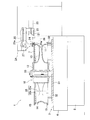
- the decoration device 101 includes a pad printer 102, a wheel moving mechanism 105, a pad cleaner unit 106, a drying device 107, a control unit (not shown), and the like.
- the arrow F indicates the front
- the arrow B indicates the rear
- the arrow R indicates the right
- the arrow L indicates the left.
- the decoration device 101 will be described using the front, rear, left, and right directions shown in the drawings.
- the wheel moving mechanism 105 includes a support member 151 and a wheel drive motor 152.
- a wheel fixing shaft 152 a is connected to the wheel drive motor 152.
- the wheel fixing shaft 152a is rotatably supported by the support member 151.
- the wheel fixing shaft 152a extends in the front-rear direction (horizontal direction).
- the wheel fixing shaft 152a is inserted through the hub portion 12 of the vehicle wheel 10.
- the vehicle wheel 10 is detachably fixed to the wheel fixing shaft 152a.
- the vehicle wheel 10 is positioned and attached to the wheel fixing shaft 152a.
- the wheel moving mechanism 105 may have a configuration in which the support member 151 is installed on an upper portion of a pedestal that can move in the left-right direction. Thereby, it becomes easy to perform the removal
- the pad printer 102 is disposed behind the wheel moving mechanism 105.
- the pad printing machine 102 includes a pad installation unit 103 in which a pad 131 is installed and a plate roll installation unit 104 in which two plate rolls 141w and 141c are installed.
- the pad installation unit 103 includes a pad 131, a front / rear slide base 132, a left / right slide base 133, and a pad drive motor 134.
- the front / rear slide table 132 is installed on a rail 135 extending in the front / rear direction, and is movable in the front / rear direction.
- the front / rear slide table 132 is driven in the front / rear direction by a drive source (not shown).
- This drive source is controlled by the control unit of the decoration device 101. The operator may manually move the front / rear slide table 132 in the front / rear direction without providing a drive source.
- a rail 136 extending in the left-right direction is formed on the upper surface of the front / rear slide table 132.
- the left / right slide table 133 is installed on the rail 136 and is movable in the left / right direction.
- the left / right slide table 133 is driven in the left / right direction by a drive source (not shown). This drive source is controlled by the control unit of the decoration device 101. Note that the operator may manually move the left / right slide base 133 in the left / right direction without providing a drive source.
- the pad drive motor 134 is installed on the left / right slide table 133 and moves integrally with the left / right slide table 133.
- a pad fixing shaft 134 a extending in the front-rear direction is connected to the pad drive motor 134.
- the pad fixing shaft 134a is disposed in parallel with the wheel fixing shaft 152a.
- the pad drive motor 134 (and the pad fixing shaft 134a) can be moved in the vertical direction by a vertical movement mechanism (not shown) of the pad installation unit 103.
- This vertical movement mechanism may be configured to move the pad drive motor 134 for each of the left and right slide tables 133, or may be configured to move the pad drive motor 134 relative to the slide table 133.
- the operation of the vertical movement mechanism may be controlled by the control unit of the decoration device 101 or may be moved manually.
- the pad 131 is formed in a cylindrical shape.
- the outer peripheral surface 131a of the pad 131 has a circular cross-sectional shape.
- the pad fixing shaft 134a is inserted through the central hole of the pad 131.
- the pad 131 is detachably fixed to a pad fixing shaft 134a (pad fixing jig).
- the center axis of the rim portion 11 of the vehicle wheel 10 fixed to the wheel fixing shaft 152a extends in the direction of the center axis of the outer peripheral surface 131a of the pad 131 fixed to the pad fixing shaft 134a.
- the pad 131 fixed to the pad fixing shaft 134a is located at the same height as the substantially central portion in the vertical direction of the vehicle wheel 10 fixed to the wheel fixing shaft 152a.
- the pad 131 is rotationally driven counterclockwise as viewed from the front. That is, the rotation direction of the pad 131 by the pad drive motor 134 and the rotation direction of the vehicle wheel 10 by the wheel drive motor 152 are the same.
- the pad 131 is made of an elastically deformable material such as silicon rubber or urethane.
- the pad 131 is softer than the pad 24 of the first embodiment and has a Young's modulus smaller than that of the pad 24.
- the outer diameter of the pad 131 is constant in the cylinder axis direction of the pad 131.
- the outer diameter of the pad 131 is the radial direction of the space between the axial end portion (decorative surface) of the inner peripheral surface of the bottom wall portion 14 of the rim portion 11 of the vehicle wheel 10 and the outer peripheral surface of the hub portion 12. Less than length.
- the circumferential length of the outer peripheral surface 131a of the pad 131 is slightly longer than the circumferential length of the decorative portions 60a to 60c.
- the plate roll installation unit 104 is arranged on the left side of the pad installation unit 103.
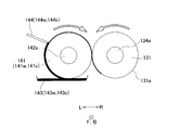
- the plate roll setting unit 104 includes two plate rolls 141w and 141c, a plate roll drive motor 142, two ink trays 143w and 143c, and two squeegees 144w and 144c (see FIG. 11).
- the plate rolls 141w and 141c may be collectively referred to as a plate roll 141.
- Ink trays 143w and 143c may be collectively referred to as ink tray 143.
- the squeegees 144w and 144c may be collectively referred to as the squeegee 144.
- the plate roll drive motor 142 is connected to a plate roll fixed shaft 142a extending in the front-rear direction.
- the plate rolls 141w and 141c are formed in a cylindrical shape.
- the plate roll fixing shaft 142a is inserted into the center hole of the plate rolls 141w and 141c and fixed to the plate rolls 141w and 141c.
- the plate rolls 141w and 141c are rotationally driven in the direction opposite to the pad 131 (clockwise as viewed from the front).
- the plate rolls 141w and 141c are intaglio plates in which the groove of the line 61 is engraved on the outer peripheral surface. Grooves of the same shape are formed on the plate rolls 141w and 141c.
- the outer diameters of the plate rolls 141w and 141c of the present embodiment are the same as the outer diameter of the pad 131, but may not be the same.
- the ink trays 143w and 143c are disposed below the plate rolls 141w and 141c, respectively. Inks of different colors are supplied to the ink trays 143w and 143c. In the present embodiment, color ink is supplied to the front ink tray 143c, and white ink is supplied to the rear ink tray 143w. As shown in FIG. 11, the lowermost ends of the plate rolls 141w and 141c are in contact with the ink in the ink trays 143w and 143c.
- the squeegees 144w and 144c are respectively arranged on the upper left of the plate rolls 141w and 141c. The tips of the squeegees 144w and 144c are in contact with the outer peripheral surfaces of the plate rolls 141w and 141c, respectively.
- the pad drive motor 134 and the plate roll drive motor 142 are operated while the outer peripheral surface 131 a (transfer surface) of the pad 131 is in contact with the outer peripheral surface of the plate roll 141.
- the pad 131 and the plate roll 141 are rotated at the same speed.
- the ink adhering to the plate roll 141 from the ink tray 143 moves upward as the plate roll 141 rotates. Excess ink protruding from the groove of the plate roll 141 is scraped off by the squeegee 144.
- the ink in the groove of the plate roll 141 adheres (transfers) to the outer peripheral surface 131 a of the pad 131 at the contact point between the plate roll 141 and the pad 131.
- ink is adhered to the front portion of the outer peripheral surface 131a of the pad 131.
- the front / rear slide table 132 and the left / right slide table 133 are moved to move the front portion of the pad 131 to the vehicle wheel 10 as shown in FIG. Arranged inside the rim 11. More specifically, the pad 131 is disposed inside the rim portion 11 and at a position below the hub portion 12. Subsequently, as shown in FIG. 13, the pad 131 is lowered by a vertical movement mechanism (not shown) of the pad installation unit 103, and the lower end portion of the front portion of the outer peripheral surface 131 a of the pad 131 is moved to the bottom wall portion 14 of the rim portion 11.
- the pad drive motor 134 and the wheel drive motor 152 are operated to rotate the pad 131 and the vehicle wheel 10. More specifically, the movement distance of the outer peripheral surface 131a of the pad 131 per unit time and the axial end portion (decorative surface) of the inner peripheral surface of the bottom wall portion 14 of the rim portion 11 of the vehicle wheel 10 per unit time. ) To rotate the pad 131 and the vehicle wheel 10 so that the movement distance is substantially the same. As a result, the ink attached to the outer peripheral surface 131 a of the pad 131 is retransferred to the rim portion 11, and the line 61 is printed on the rim portion 11.
- the pad cleaner unit 106 is for removing ink remaining on the pad 131 after ink is attached to the rim unit 11. As illustrated in FIG. 14, the pad 131 is rotated by bringing the pad 131 into contact with the pad cleaner unit 106 and rotating the pad 131.
- the installation position of the pad cleaner unit 106 is not particularly limited as long as the pad cleaner unit 106 can be cleaned in a state where the pad 131 is fixed to the pad fixing shaft 134a.
- the pad cleaner unit 106 is disposed behind the plate roll installation unit 104. When changing the color of the ink attached to the pad 131, the pad 131 is cleaned by the pad cleaner unit 106. Further, the pad 131 is cleaned by the pad cleaner unit 106 every time a predetermined number of times of printing is performed.
- the drying device 107 is a device that blows air to a portion of the rim portion 11 where the ink is adhered during pad printing (during rotation of the vehicle wheel 10) to dry the ink.
- the installation position of the drying device 107 is not particularly limited as long as the ink attached to the rim portion 11 can be dried.
- the drying device 107 is disposed to face the right portion of the rim portion 11 of the vehicle wheel 10 fixed to the wheel fixing shaft 152a.
- color ink is printed over white ink. Therefore, by drying the white ink transferred to the rim portion 11 with the drying device 107, it is possible to prevent printing with color ink from bleeding or collapsing.
- Control unit controls operations of the pad printing machine 102, the wheel moving mechanism 105, and the drying device 107.
- the control unit includes a CPU (Central Processing Unit), a ROM (Read Only Memory), a RAM (Random Access Memory), and the like.
- the control unit causes the CPU to execute various processes according to data and programs stored in the RAM and ROM, and decorates the inner peripheral surface of the bottom wall portion 14 of the rim portion 11 of the vehicle wheel 10 with the decoration portions 60a to 60c. Form.
- FIG. 16 is a diagram illustrating a process of decorating the vehicle wheel.
- the vehicle wheel 10 is fixed to the wheel fixing shaft 152a (fixing step).
- One end in the circumferential direction of the decorating position 64 a on the inner peripheral surface of the bottom wall portion 14 of the rim portion 11 of the vehicle wheel 10 (specifically, the end portion in front of the vehicle wheel 10 in the rotational direction) is the bottom wall portion 14.
- the vehicle wheel 10 is positioned so as to be positioned at the lowermost end.
- the outer peripheral surface 131a of the pad 131 fixed to the pad fixing shaft 134a is brought into contact with the outer peripheral surface of the rear plate roll 141w of the two plate rolls 141w and 141c. Then, the plate roll drive motor 142 and the pad drive motor 134 are driven to rotate the plate roll 141 and the pad 131, respectively. As a result, white ink is adhered from the plate roll 141w to the outer peripheral surface 131a of the pad 131 (first adhesion step).
- the left / right slide table 133 and the front / rear slide table 132 are moved, and the pad 131 to which the white ink is attached is arranged inside the rim portion 11 of the vehicle wheel 10.
- the lower end portion (a part of the transfer surface) of the outer peripheral surface 131 a of the pad 131 is moved to the inner peripheral surface of the bottom wall portion 14 of the rim portion 11 of the vehicle wheel 10 by a vertical movement mechanism (not shown) of the pad installation portion 103. It presses on the circumferential direction one end (end part of the rotation direction front of the vehicle wheel 10) of the decorating position 64a. More specifically, a portion of the outer peripheral surface 131a of the pad 131 to which the ink forming one end in the circumferential direction of the line 61 is attached is pressed against one end in the circumferential direction of the decorating position 64a.
- the pad drive motor 134 and the wheel drive motor 152 are driven to rotate the pad 131 and the vehicle wheel 10 respectively.
- the ink attached to the outer peripheral surface 131 a of the pad 131 is transferred to the entire circumferential direction of the decoration position 64 a of the rim portion 11.
- the line 61 is printed with the white ink in the decoration position 64a.
- the pad 131 is moved from the position in contact with the plate roll 141, and a part of the outer peripheral surface 131 a of the pad 131 is brought into contact with the inner peripheral surface (decorative surface) of the bottom wall portion 14 of the rim portion 11.
- the process up to this is referred to as a contact process.
- the pad 131 is not elastically deformed.
- the pad fixing shaft 134a is further moved to the rim portion from a state in which a part of the outer peripheral surface 131a of the pad 131 is brought into contact with a part of the decoration position 64a on the inner peripheral surface of the bottom wall portion 14 of the rim portion 11 in the contact step.
- the pressing step is defined by combining the step of rotating the pad 131 in the state and decorating the entire circumferential direction of the decorating position 64a. In the pressing process, the pad 131 is elastically deformed.
- the process of rotating the vehicle wheel 10 is a moving process.
- the vehicle wheel 10 is relatively moved in the circumferential direction of the rim portion 11 with respect to the position of the pad 131 when pressed against the rim portion 11.
- a part of movement process is performed simultaneously with a part of press process.
- the part of the pressing process after the rotation of the pad 131 is started is performed at the same time as the moving process (detailed decorating moving process described later).
- limb part 11 by the circumferential direction length of the decoration position 64a from the start time among the movement processes is set as a decoration movement process.
- a part after the above-mentioned decoration movement process is made into an intermediate movement process among movement processes.
- the rim portion 11 rotates by a distance in the circumferential direction between the decoration position 64a and the decoration position 64b.
- middle movement process is not limited to the case where the decoration position 64a is decorated, When the decoration positions 64b and 64c are decorated Also applies.
- a drying process is performed in which the ink attached to the rim portion 11 is dried by the drying device 107.
- the area of the rim portion 11 to which the ink has adhered has not moved to the position of the drying device 107. Strictly speaking, the drying process for drying the ink is only part of the moving process. It will be done at the same time.
- the pad 131 is moved away from the rim portion 11 and moved to the position of the plate roll 141w.
- the step of moving the pad 131 from the position in contact with the rim portion 11 to the position of the plate roll 141 (141w or 141c) is referred to as a pad returning step.
- the second attaching process is performed in the same manner as the first attaching process.
- the lower end portion of the outer peripheral surface 131a of the pad 131 to which the white ink is attached is connected to one end in the circumferential direction of the decoration position 64b on the inner peripheral surface of the bottom wall portion 14 of the rim portion 11 of the vehicle wheel 10 (vehicle wheel). 10 at the front end in the rotational direction) (second contact step).
- a second pressing step and a second moving step are performed.
- the line 61 is printed with the white ink at the decoration position 64 b of the rim portion 11 of the vehicle wheel 10
- one circumferential end of the decoration position 64 c is located at the lower end portion of the bottom wall portion 14.
- the second pad return process is performed in the same manner as the first pad return process.
- the 3rd adhesion process is performed.
- the lower end portion of the outer peripheral surface 131a of the pad 131 to which the white ink is attached is brought into contact with one end in the circumferential direction of the decoration position 64c on the inner peripheral surface of the bottom wall portion 14 of the rim portion 11 of the vehicle wheel 10 ( Third contact step).
- a third pressing step and a third moving step are performed. Accordingly, the line 61 is printed with the white ink at the decoration position 64 c of the rim portion 11 of the vehicle wheel 10, and one circumferential end of the decoration position 64 a is located at the lower end of the bottom wall portion 14.
- the pad 131 is moved away from the rim portion 11 to the position of the pad cleaner portion 106. Then, the white ink remaining on the pad 131 is removed by the pad cleaner unit 106. When the cleaning of the pad 131 is completed, the pad 131 is moved to the position of the plate roll 141c as shown in FIG.
- the process of cleaning the pad 131 by the pad cleaner unit 106 is referred to as a pad cleaning process. The pad cleaning process is performed during the process of moving the pad 131 from the position in contact with the rim portion 11 to the position of the plate roll 141c (the third pad returning process).
- the vehicle wheel 10 may be rotated to dry the ink attached to the rim portion 11 by the drying device 107.
- one end in the circumferential direction of the decoration position 64a of the rim portion 11 of the vehicle wheel 10 (specifically, the end portion in the rotational direction of the vehicle wheel 10) is the end of the rim portion 11.
- the rotation of the vehicle wheel 10 is stopped.
- the plate roll drive motor 142 and the pad drive motor 134 are driven to attach color ink from the plate roll 141c to the outer peripheral surface 131a of the pad 131 (fourth attachment step).
- the lower end portion of the outer peripheral surface 131 a of the pad 131 to which the color ink is attached is brought into contact with one end in the circumferential direction of the decoration position 64 a on the inner peripheral surface of the bottom wall portion 14 of the rim portion 11 of the vehicle wheel 10. (Fourth contact step).
- the line 61 is already printed with the white ink at the decoration position 64a.
- a fourth pressing step and a fourth moving step are performed. Thereby, the line 61 is printed with the color ink in the decoration position 64a of the rim
- the pad 131 is moved to the position of the plate roll 141c (fourth pad returning step), and the fifth attaching step is performed. And after the 5th contact process, the 5th press process and the 5th movement process are performed, and the decoration part 60b is formed in the decoration position 64b. Subsequently, the pad 131 is moved to the position of the plate roll 141c (the fifth pad returning step), and the sixth attaching step is performed. And after the 6th contact process, the 6th press process and the 6th movement process are performed, and the decoration part 60c is formed in the decoration position 64c.
- the pad 131 of the pad printing machine 102 decorates a range longer than the maximum length (diameter) of the pad 131 of the rim portion 11 of the vehicle wheel 10.
- the range decorated by the pad 131 is longer than the peripheral length of the outer peripheral surface 131a of the pad 131.
- the range decorated by the pad 131 is approximately three times the circumferential length of the outer peripheral surface 131a of the pad 131.
- decorative portions 60a to 60c having the same pattern are arranged in the circumferential direction of the rim portion 11. It is formed side by side.
- the decoration portions 60a to 60c are formed by a decoration technique that directly attaches ink to the decoration surface of the rim portion 11, that is, by printing.
- the decoration portions 60a to 60c have a pattern in which the length in the direction orthogonal to the circumferential direction of the rim portion 11 is not constant. Such a pattern may not be decorated by painting on a groove for decoration, painting using masking, or sticking a seal. Even if it is possible, it takes time and productivity decreases.
- the decoration portions 60a to 60c of the present embodiment are formed by printing, so that the degree of freedom in decoration and productivity can be improved. Therefore, according to the present embodiment, the vehicle decoration wheel 10B in which the decoration portions 60a to 60c are formed on the rim portion 11 can be manufactured while maintaining high productivity even if the degree of decoration freedom is high. Can be realized.
- the vehicle decoration wheel 10B is decorated by pad printing.
- Pad printing is a printing technique in which after ink is transferred from a plate to a pad, the pad is pressed against a decoration target and printed (decorated). Therefore, the degree of freedom in decoration and productivity can be further enhanced as compared with the case of decorating by painting on a groove for decoration or painting using masking or sticking a seal.
- the pad 131 has a range that is longer than the maximum length of the transfer surface 131 a of the pad 131 on the inner peripheral surface (decorative surface) of the bottom wall portion 14 of the rim portion 11 of the vehicle wheel 10. Has been.
- the pad 131 may be small. Since the pad 131 is small, it is easy to ensure the uniformity of pressure when the pad 131 is pressed against the vehicle wheel 10. Therefore, even if it is a complicated picture, since it can decorate with a sufficient precision, a decoration freedom degree can be improved more.
- the decoration portions 60a to 60c are arranged at intervals in the circumferential direction of the rim portion 11. Therefore, for example, the decorative portion 60a and the decorative portion 60b are partially overlapped, or compared to the case where the end portions of the decorative portion 60a and the end portions of the decorative portion 60b are the same. Print misalignment between 60a and the decorating part 60b is not noticeable. Therefore, even if the decorating portions 60a to 60c are slightly shifted, it is difficult to cause a defect, so that productivity can be improved.
- the end portions in the circumferential direction of the decorative portions 60a to 60c extend in the direction of the central axis of the rim portion 11 (the direction perpendicular to the circumferential direction of the rim portion 11), the ink forming the end portions is It tends to remain on the outer peripheral surface 131 a of the pad 131.
- the end portions in the circumferential direction of the decoration portions 60a to 60c extend obliquely with respect to the direction of the central axis of the rim portion 11 (direction perpendicular to the circumferential direction of the rim portion 11). ing. For this reason, the ink forming the end portion hardly remains on the outer peripheral surface 131 a of the pad 131. Therefore, it is easier to ensure the print quality of the decorating parts 60a to 60c. Therefore, productivity can be further increased.
- FIG. 17 shows a vehicle wheel 10C of the present embodiment (hereinafter, referred to as a vehicle decoration wheel 10C) decorated by a decoration device 201 described later.
- the decoration device 201 decorates the vehicle wheel 10 by pad printing. That is, the vehicle decoration wheel 10C is decorated by pad printing.
- Decorative portions 70a to 70c arranged in the circumferential direction are formed on the outer surface of the side wall portion 15 of the rim portion 11 of the vehicle decoration wheel 10C.
- the positions where the decoration portions 70a to 70c of the rim portion 11 of the vehicle wheel 10 are formed are referred to as decoration positions 74a to 74c.
- the entire circumferential direction of the outer surface of the side wall portion 15 of the rim portion 11 of the vehicle wheel 10 corresponds to the decorative surface of the present invention.
- the decoration portions 70a to 70c are configured by a line 71.
- the decorative portions 70a to 70c are arranged at a pitch of 120 °.
- the decorating portions 70a to 70c are arranged at intervals in the circumferential direction of the rim portion 11.
- the circumferential length of the decorative portions 70a to 70c is a length corresponding to an angle range of about 90 ° of the side wall portion 15 of the rim portion 11, but is not limited thereto.
- Both end portions in the circumferential direction of the decoration portions 70a to 70c (line 71) are inclined with respect to the radial direction of the rim portion 11 (direction perpendicular to the circumferential direction of the rim portion 11). Thereby, in the circumferential direction of the rim portion 11, the lengths of the decorative portions 70a to 70c (line 71) in the radial direction (direction perpendicular to the circumferential direction) are not constant.
- the decoration portions 70a to 70c are composed of a plurality of lines arranged at intervals in the circumferential direction of the rim portion 11. Both circumferential ends of the plurality of lines constituting the line 71 are inclined with respect to the radial direction of the rim portion 11 (direction perpendicular to the circumferential direction of the rim portion 11).
- the lines 71a located at both ends in the circumferential direction of the line 71 correspond to the first pattern of the present invention.
- the line 71b adjacent to the line 71a in the circumferential direction corresponds to the second pattern of the present invention.
- the decoration portions 70a to 70c are white or light color close to white.
- the decoration portions 70a to 70c have the same color.
- the decoration portions 70a to 70c are formed of ink.
- the ink used in the present embodiment has a higher solvent content than the ink used in the first embodiment.
- the decorative portions 70a to 70c are formed by only one printing with white or light white ink close to white.
- the decoration portions 70a to 70c correspond to the first decoration portion, the second decoration portion, and the third decoration portion of the present invention.
- the decoration device 201 includes a pad printing machine 202, a wheel moving mechanism 205, a control unit (not shown), and the like.
- the arrow F indicates the front
- the arrow B indicates the rear
- the arrow R indicates the right
- the arrow L indicates the left.
- the decoration device 201 will be described using the front, rear, left, and right directions shown in the drawings.
- the wheel moving mechanism 205 has a front / rear slide part 251 and a wheel drive motor 252 (see FIG. 20).
- the front / rear slide part 251 is installed on a rail 253 extending in the front / rear direction, and is movable in the front / rear direction.
- the front / rear slide part 251 is driven in the front / rear direction by a drive source (not shown). This drive source is controlled by the control unit of the decoration device 201. The operator may manually move the front / rear slide part 251 in the front / rear direction without providing a drive source.
- a wheel drive motor 252 is accommodated in the front / rear slide portion 251.
- the wheel drive motor 252 moves in the front-rear direction integrally with the front-rear slide part 251.
- a wheel fixing shaft 252a extending in the vertical direction is connected to the wheel drive motor 252.
- the wheel fixing shaft 252a protrudes from the upper surface of the front / rear slide portion 251.
- the wheel fixing shaft 252a is inserted into the hub portion 12 of the vehicle wheel 10.
- the vehicle wheel 10 is detachably fixed to the wheel fixing shaft 252a.
- the vehicle wheel 10 is positioned and attached to the wheel fixed shaft 252a.
- the wheel drive motor 252 By operating the wheel drive motor 252 in a state where the vehicle wheel 10 is fixed to the wheel fixing shaft 252a, the vehicle wheel 10 is driven to rotate clockwise as viewed from above.
- the pad printer 202 is disposed behind the wheel moving mechanism 205.
- the pad printing machine 202 includes a pad installation unit 203 on which a pad 231 is installed and a plate roll installation unit 204 on which a plate roll 241 is installed.
- the pad installation unit 203 includes a pad 231, a left / right slide base 232, and a pad drive motor 233.
- the left / right slide base 232 is installed on a rail 234 extending in the left / right direction, and is movable in the left / right direction.
- the left / right slide base 232 is driven in the left / right direction by a drive source (not shown). This drive source is controlled by the control unit of the decoration device 201. Note that an operator may manually move the left / right slide base 232 in the left / right direction without providing a drive source.
- the pad drive motor 233 is installed on the left / right slide base 232 and moves in the left / right direction integrally with the left / right slide base 232.
- a pad fixing shaft 233a extending in the front-rear direction is connected to the pad drive motor 233.
- the pad fixing shaft 233a extends in a direction orthogonal to the wheel fixing shaft 252a.
- the pad drive motor 233 (and the pad fixing shaft 233a) can be moved in the vertical direction by a vertical movement mechanism (not shown) of the pad installation unit 203.
- This vertical movement mechanism may be configured to move the pad drive motor 233 for each left and right slide base 232, or may be configured to move the pad drive motor 233 relative to the left and right slide base 232.
- the operation of the vertical movement mechanism may be controlled by the control unit of the decoration device 201 or may be moved manually.
- the shape and material of the pad 231 are the same as the pad 131 of the second embodiment.
- the circumferential length of the outer peripheral surface 231a of the pad 231 is slightly longer than the circumferential length of the decorative portions 70a to 70c.
- the pad fixing shaft 233a is inserted through the hole in the center of the pad 231.
- the pad 231 is detachably fixed to a pad fixing shaft 233a (pad fixing jig).
- the central axis of the rim portion 11 of the vehicle wheel 10 fixed to the wheel fixing shaft 252a extends in a direction orthogonal to the central axis of the outer peripheral surface 231a of the pad 231 fixed to the pad fixing shaft 233a.
- the plate roll installation unit 204 is arranged on the left side of the pad installation unit 203.
- the plate roll installation unit 204 includes a plate roll 241, a plate roll drive motor 242, an ink tray 243, and a squeegee (not shown).
- a plate roll fixed shaft 242a is connected to the plate roll drive motor 242.
- the plate roll fixing shaft 242a extends in parallel with the pad fixing shaft 233a.
- the plate roll 241 is formed in a cylindrical shape.
- a plate roll fixing shaft 242a is inserted through a hole in the center of the plate roll 241, and the plate roll 241 is fixed to the plate roll fixing shaft 242a. By operating the plate roll drive motor 242, the plate roll 241 is rotationally driven in the direction opposite to the pad 231 (clockwise as viewed from the front).
- the plate roll 241 is an intaglio plate in which the groove of the line 71 is engraved on the outer peripheral surface.
- the outer diameter of the plate roll 241 is the same as the outer diameter of the pad 231, but may not be the same.
- the plate roll 241 is disposed at the same position as the pad 231 when viewed from the left-right direction.
- the ink tray 243 is disposed below the plate roll 241. Ink is supplied to the ink tray 243. The lowermost end of the plate roll 241 contacts the ink in the ink tray 243. Similar to the squeegee 144 (see FIG. 11) of the second embodiment, the squeegee (not shown) is disposed on the upper left side of the plate roll 241, and the tip thereof contacts the outer peripheral surface of the plate roll 241.
- the pad driving motor 233 and the plate roll driving motor 242 are operated to The roll 241 is rotated at the same speed.
- ink is attached (transferred) from the plate roll 241 to the outer peripheral surface 231a of the pad 231.
- ink is attached to the rear portion of the outer peripheral surface 231a of the pad 231.
- the pad 231 is moved to the rim portion 11 of the vehicle wheel 10 as shown in FIG. It arrange
- the pad 231 is lowered by a vertical movement mechanism (not shown) of the pad installation portion 203, and the lower end portion of the outer peripheral surface 231a of the pad 231 is moved to the outer surface of the side wall portion 15 of the rim portion 11 as shown in FIG. Press on the decorative surface.
- the pad drive motor 233 and the wheel drive motor 252 are operated to rotate the pad 231 and the vehicle wheel 10.
- the movement distance of the outer peripheral surface 231a of the pad 231 per unit time and the movement distance of the side wall portion 15 (decorative surface) of the rim portion 11 of the vehicle wheel 10 per unit time are substantially the same.
- the pad 231 and the vehicle wheel 10 are rotated.
- the ink attached to the outer peripheral surface 231 a of the pad 231 is retransferred to the rim portion 11, and the line 71 is printed on the rim portion 11.
- the control unit (not shown) controls the operations of the pad printing machine 202 and the wheel moving mechanism 205.
- the control unit includes a CPU (Central Processing Unit), a ROM (Read Only Memory), a RAM (Random Access Memory), and the like.
- the control unit causes the CPU to execute various processes in accordance with data and programs stored in the RAM and ROM, and forms the decorative portions 70a to 70c on the outer surface of the side wall portion 15 of the rim portion 11 of the vehicle wheel 10. .
- FIG. 21 is a diagram illustrating a process of decorating the vehicle wheel.
- the vehicle wheel 10 is fixed to the wheel fixing shaft 252a (fixing step).
- One end in the circumferential direction of the decoration position 74a of the side wall 15 of the vehicle wheel 10 (specifically, the front end in the rotational direction of the vehicle wheel 10) is positioned at the rear end of the side wall 15 so that the vehicle is used.
- the wheel 10 is positioned.
- the outer peripheral surface 231a of the pad 231 fixed to the pad fixing shaft 233a is brought into contact with the outer peripheral surface of the plate roll 241. Then, the plate roll drive motor 242 and the pad drive motor 233 are driven to rotate the plate roll 241 and the pad 231 respectively. Thereby, ink is made to adhere from the plate roll 241 to the outer peripheral surface 231a of the pad 231 (first attaching step).
- the left / right slide base 232 and the front / rear slide part 251 are moved, and the pad 231 to which ink is attached is disposed above the outer surface of the side wall part 15 of the rim part 11 of the vehicle wheel 10.
- the lower end portion (a part of the transfer surface) of the outer peripheral surface 231a of the pad 231 is decorated on the outer surface of the side wall portion 15 of the rim portion 11 of the vehicle wheel 10 by a vertical movement mechanism (not shown) of the pad installation portion 203.
- 74a is pressed against one end in the circumferential direction (the front end in the rotational direction of the vehicle wheel 10). More specifically, a portion of the outer peripheral surface 231a of the pad 231 to which the ink forming one end in the circumferential direction of the line 71 is attached is pressed against one end in the circumferential direction of the decorating position 74a.
- the pad drive motor 233 and the wheel drive motor 252 are driven to rotate the pad 231 and the vehicle wheel 10 respectively.
- the ink attached to the outer peripheral surface 231 a of the pad 231 is transferred to the entire circumferential direction of the decoration position 74 a of the rim portion 11.
- the decoration part 70a is formed in the decoration position 74a.
- the rotation of the pad 231 and the vehicle wheel 10 is stopped. At this time, until one end in the circumferential direction of the decoration position 74b of the rim portion 11 of the vehicle wheel 10 (specifically, the front end portion in the rotational direction of the vehicle wheel 10) is positioned at the rear end portion of the side wall portion 15. After the pad 231 and the vehicle wheel 10 are rotated, the rotation of the pad 231 and the vehicle wheel 10 is stopped. Therefore, the pad 231 rotates more than one round.
- the process of moving the pad 231 from the position in contact with the plate roll 241 and bringing a part of the outer peripheral surface 231a of the pad 231 into contact with the outer surface (decorative surface) of the side wall portion 15 of the rim portion 11 is performed. Is the contact step. In the contact process, the pad 231 is not elastically deformed. Further, from the state in which a part of the outer peripheral surface 231 a of the pad 231 is brought into contact with a part of the decoration position 74 a on the outer surface of the side wall 15 of the rim 11 in the contact process, the pad fixing shaft 233 a is further directed toward the rim 11.
- the process of rotating the vehicle wheel 10 is a moving process.
- the vehicle wheel 10 is relatively moved in the circumferential direction of the rim portion 11 with respect to the position of the pad 231 when pressed against the rim portion 11.
- a part of the moving process is performed simultaneously with a part of the pressing process.
- the portion after the rotation of the pad 231 is started is performed simultaneously with the moving step (decorative moving step described later in detail).
- limb part 11 by the circumferential direction length of the decoration position 74a from the time of the start among the movement processes is set as a decoration movement process.
- a part after the above-mentioned decoration movement process is made into an intermediate movement process among movement processes.
- the rim portion 11 rotates by a distance in the circumferential direction between the decoration position 74a and the decoration position 74b.
- middle movement process is not limited to the case where the decoration position 74a is decorated, When decorating the decoration positions 74b and 74c Also applies.
- the pad 231 is moved away from the rim portion 11 to the position of the plate roll 241.
- the process of moving the pad 231 from the position in contact with the rim portion 11 to the position of the plate roll 241 is referred to as a pad returning process.
- the second attaching process is performed in the same manner as the first attaching process.
- the lower end portion of the outer peripheral surface 231a of the pad 231 to which the ink is attached is connected to one end in the circumferential direction of the decoration position 74b on the outer surface of the side wall portion 15 of the rim portion 11 of the vehicle wheel 10 (forward in the rotational direction of the vehicle wheel 10).
- the second contact step Subsequently, a second pressing step and a second moving step are performed.
- the decoration part 70b is formed in the decoration position 74b of the rim
- the circumferential direction one end of the decoration position 74c is located in the rear-end part of the side wall part 15.
- the second pad return process is performed in the same manner as the first pad return process.
- the 3rd adhesion process is performed.
- the lower end portion of the outer peripheral surface 231a of the pad 231 to which the white ink is attached is brought into contact with one end in the circumferential direction of the decoration position 74c on the outer surface of the side wall portion 15 of the rim portion 11 of the vehicle wheel 10 (third time Contact process).
- a third pressing step and a third moving step are performed.
- the decoration part 70c is formed in the decoration position 74c of the rim
- the pad 231 of the pad printing machine 202 decorates a range longer than the maximum length (diameter) of the pad 231 of the rim portion 11 of the vehicle wheel 10.
- the range decorated by the pad 231 is longer than the peripheral length of the outer peripheral surface 231a of the pad 231.
- the range decorated by the pad 231 is approximately three times the peripheral length of the outer peripheral surface 231a of the pad 231.
- decorative portions 70a to 70c having the same pattern are formed side by side in the circumferential direction of the rim portion 11.
- the decoration portions 70a to 70c are formed by a decoration technique in which ink is directly attached to the decoration surface of the rim portion 11, that is, printing.
- the decoration portions 70a to 70c have a pattern in which the length in the direction orthogonal to the circumferential direction of the rim portion 11 is not constant. Such a pattern may not be decorated by painting on a groove for decoration, painting using masking, or sticking a seal. Even if it is possible, it takes time and productivity decreases.
- the decoration portions 70a to 70c of the present embodiment are formed by printing, so that the degree of freedom in decoration and productivity can be improved. Therefore, according to the present embodiment, the vehicle decoration wheel 10C in which the decoration portions 70a to 70c are formed on the rim portion 11 can be manufactured while maintaining high productivity even if the degree of freedom in decoration is high. Can be realized.
- the vehicle decoration wheel 10C is decorated by pad printing.
- Pad printing is a printing technique in which after ink is transferred from a plate to a pad, the pad is pressed against a decoration target and printed (decorated). Therefore, the degree of freedom in decoration and productivity can be further enhanced as compared with the case of decorating by painting on a groove for decoration or painting using masking or sticking a seal.
- the pad 231 decorates a range longer than the maximum length of the pad transfer surface on the outer surface (decorative surface) of the side wall portion 15 of the rim portion 11 of the vehicle wheel 10. Therefore, even if the outer peripheral surface (decorative surface) of the side wall 15 of the rim 11 is long, the pad 231 may be small. Since the pad 231 is small, it is easy to ensure uniformity of pressure when the pad 231 is pressed against the vehicle wheel 10. Therefore, even if it is a complicated picture, since it can decorate with a sufficient precision, a decoration freedom degree can be improved more.
- the decoration portions 70a to 70c are arranged at intervals in the circumferential direction of the rim portion 11. Therefore, for example, compared with the case where the position of the one end part of the decoration part 70a in the circumferential direction and the one end part of the decoration part 70b in the circumferential direction are the same, a shift of the boundary between the decoration part 70a and the decoration part 70b occurs. Hateful. Therefore, productivity can be increased.
- the end portions in the circumferential direction of the decorative portions 70a to 70c extend in the radial direction of the rim portion 11, ink forming the end portions tends to remain on the outer peripheral surface 231a of the pad 231.
- the end portions in the circumferential direction of the decoration portions 70a to 70c extend obliquely with respect to the radial direction of the rim portion 11 (the direction perpendicular to the circumferential direction of the rim portion 11). .
- the ink forming the end portion hardly remains on the outer peripheral surface 231 a of the pad 231. Therefore, it is easier to ensure the print quality of the decorative portions 70a to 70c. Therefore, productivity can be further increased.
- the decoration portions 70a to 70c are configured by a line 71.
- the line 71 is composed of a plurality of lines (including 71 a and 71 b) arranged at intervals in the circumferential direction of the rim portion 11. Therefore, it is easy to make use of the gap between the decorative parts in the design. That is, since there is a gap between the line 71a and the line 71b, the gap between the decorative portions is less noticeable.
- limb part 11 of the some line (71a, 71b are included) which comprise the line 71 are with respect to the radial direction (direction orthogonal to the circumferential direction of the rim
- FIG. 22 shows a vehicle wheel 10D of the present embodiment (hereinafter referred to as a vehicle decoration wheel 10D) decorated by a decoration device 301 described later.
- the decoration device 301 decorates the vehicle wheel 10 by pad printing. That is, the vehicle decoration wheel 10D is decorated by pad printing.
- Decorative portions 80a to 80c and 81a to 81c arranged in the circumferential direction are formed on the outer surface of the side wall portion 15 of the rim portion 11 of the vehicle decorative wheel 10D.
- the decoration portions 80a to 80c are formed at the decoration positions 54a to 54c of the rim portion 11 of the vehicle wheel 10 in the same manner as the decoration portions 50a to 50c of the first embodiment.
- the decoration portions 81a to 81c are formed at the decoration positions 55a to 55c of the rim portion 11 of the vehicle wheel 10 in the same manner as the decoration portions 51a to 51c of the first embodiment.
- the decorating parts 80a to 80c are composed of characters 52, like the decorating parts 50a to 50c of the first embodiment.
- the decoration parts 81a to 81c are configured by a line 53, like the decoration parts 51a to 51c of the first embodiment.
- the entire circumferential direction of the outer surface of the side wall portion 15 of the rim portion 11 of the vehicle wheel 10 corresponds to the decorative surface of the present invention.
- the decoration portions 80a to 80c and 81a to 81c are white or light colors close to white.
- the decoration parts 80a to 80c are the same color as each other, and the decoration parts 81a to 81c are the same color as each other.
- the decoration portions 80a to 80c and the decoration portions 81a to 81c are different colors, but may be the same color.
- the decorative portions 80a to 80c and 81a to 81c are formed of ink. As in the second embodiment, the ink used in the present embodiment has a higher solvent content than the ink used in the first embodiment.
- the decorative portions 80a to 80c and 81a to 81c are formed by only one printing with white or near white light ink.
- the decorating portions 80a to 80c correspond to the first decorating portion, the second decorating portion, and the third decorating portion of the present invention. The same can be said for the decorative portions 81a to 81c.
- the decoration device 301 includes two pad printing machines 302A and 302B, a wheel moving mechanism 205, a control unit (not shown), and the like.
- the arrow F indicates the front
- the arrow B indicates the rear
- the arrow R indicates the right
- the arrow L indicates the left.
- the decoration device 301 will be described using the front, rear, left, and right directions shown in the drawings.
- the pad printing machine 302A has the same configuration as the pad printing machine 202 of the third embodiment, except that the plate roll 341A of the plate roll installation unit 304A is different from the plate roll 241 of the third embodiment.
- the plate roll 341A is an intaglio plate in which the groove of the line 53 is engraved on the outer peripheral surface thereof.
- the pad printing machine 302B has substantially the same configuration as the pad printing machine 302A except that the arrangement direction is different from that of the pad printing machine 302A.
- the pad printing machine 302B includes a pad installation unit 303 in which the pad 331 is installed and a plate roll installation unit 304B in which the plate roll 341B is installed.
- the pad installation unit 303 includes a pad 331, a front / rear slide base 332, and a pad drive motor 333.
- the front / rear slide table 332 is installed on a rail 334 extending in the front-rear direction and is movable in the front-rear direction.
- the front / rear slide table 332 is driven in the front / rear direction by a drive source (not shown).
- This drive source is controlled by the control unit of the decoration device 301. The operator may manually move the front / rear slide table 332 in the front-rear direction without providing a drive source.
- the pad drive motor 333 is installed on the front / rear slide base 332 and moves in the front / rear direction integrally with the front / rear slide base 332.
- a pad fixing shaft 333 a extending in the left-right direction is connected to the pad drive motor 333.
- the pad fixing shaft 333a extends in a direction orthogonal to the wheel fixing shaft 252a.
- the pad drive motor 333 (and the pad fixing shaft 333a) can be moved in the vertical direction by a vertical movement mechanism (not shown) of the pad installation unit 303.
- This vertical movement mechanism may be configured to move the pad drive motor 333 for each of the front and rear slide tables 332, or may be configured to move the pad drive motor 333 relative to the front and rear slide table 332.
- the operation of the vertical movement mechanism may be controlled by the control unit of the decoration device 301 or may be moved manually.
- the shape and material of the pad 331 are the same as the pad 131 of the second embodiment.
- the circumferential length of the outer peripheral surface 331a of the pad 331 is slightly longer than the circumferential lengths of the decorative portions 80a to 80c and 81a to 81c.
- the pad fixing shaft 333a is inserted through the hole in the center of the pad 331.
- the pad 331 is detachably fixed to a pad fixing shaft 333a (pad fixing jig).
- the center axis of the rim portion 11 of the vehicle wheel 10 fixed to the wheel fixing shaft 252a extends in a direction orthogonal to the center axis of the outer peripheral surface 331a of the pad 331 fixed to the pad fixing shaft 333a.
- the plate roll installation unit 304B is disposed above the pad installation unit 303.
- the plate roll installation unit 304B includes a plate roll 341B, a plate roll drive motor 342, an ink tray 343, and a squeegee (not shown).
- a plate roll fixed shaft 342a is connected to the plate roll drive motor 342.
- the plate roll fixing shaft 342a extends in parallel with the pad fixing shaft 333a.
- the plate roll 341B is formed in a cylindrical shape.
- a plate roll fixing shaft 342a is inserted into a central hole of the plate roll 341B, and the plate roll 341B is fixed to the plate roll fixing shaft 342a.
- the plate roll 341B is rotationally driven in the direction opposite to the pad 331 (clockwise as viewed from the left).
- the plate roll 341B is an intaglio plate in which grooves of characters 52 are engraved on the outer peripheral surface.
- the outer diameter of the plate roll 341B is the same as the outer diameter of the pad 331, but may be different.
- the plate roll 341B is disposed at the same position as the pad 331.
- the ink tray 343 is disposed below the plate roll 341B. Ink is supplied to the ink tray 343. The lowermost end of the plate roll 341B is in contact with the ink in the ink tray 343.
- the squeegee (not shown) is disposed on the rear upper side of the plate roll 341B, and the tip thereof contacts the outer peripheral surface of the plate roll 341B.
- the pad drive motor 333 and the plate roll drive motor 342 are operated to rotate the pad 331 and the plate roll 341B at the same speed.
- ink is attached (transferred) from the plate roll 341 ⁇ / b> B to the outer peripheral surface 331 a of the pad 331.
- ink is attached to the right part of the outer peripheral surface 331a of the pad 331.
- the front / rear slide part 251 and the front / rear slide base 332 are moved to move the pad 331 to the rim part 11 of the vehicle wheel 10 as shown in FIG. It arrange
- the pad 331 is lowered by a vertical movement mechanism (not shown) of the pad installation portion 303, and the lower end portion of the outer peripheral surface 331 a of the pad 331 is pressed against the outer surface (decorative surface) of the side wall portion 15 of the rim portion 11.
- the pad drive motor 333 and the wheel drive motor 252 are operated to rotate the pad 331 and the vehicle wheel 10.
- the movement distance of the outer peripheral surface 331a of the pad 331 per unit time and the movement distance of the side wall portion 15 (decorative surface) of the rim portion 11 of the vehicle wheel 10 per unit time are substantially the same.
- the pad 331 and the vehicle wheel 10 are rotated.
- the ink attached to the outer peripheral surface 331 a of the pad 331 is retransferred to the rim portion 11, and the characters 52 are printed on the rim portion 11.
- the control unit (not shown) controls operations of the pad printing machines 302A and 302B and the wheel moving mechanism 205.
- the control unit includes a CPU (Central Processing Unit), a ROM (Read Only Memory), a RAM (Random Access Memory), and the like.
- the control unit causes the CPU to execute various processes according to data and programs stored in the RAM and ROM, and decorates the outer surface of the side wall portion 15 of the rim portion 11 of the vehicle wheel 10 with the decoration portions 80a to 80c, 81a to 81c is formed.
- FIG. 24 is a diagram illustrating a process of decorating the vehicle wheel.
- the vehicle wheel 10 is fixed to the wheel fixing shaft 252a (fixing step).
- one end in the circumferential direction of the decoration position 55 b of the side wall 15 of the vehicle wheel 10 (specifically, the front end in the rotational direction of the vehicle wheel 10) is at the rear end of the side wall 15.
- the vehicle wheel 10 is positioned so as to be positioned.
- the front end in the rotational direction of the vehicle wheel 10 at the decoration position 54 a is located slightly behind the right end of the side wall 15.
- the pad printer 302A causes ink to adhere from the plate roll 341A to the outer peripheral surface 231a of the pad 231
- the pad printer 302B causes ink to adhere from the plate roll 341B to the outer peripheral surface 331a of the pad 331 (first time). Adhesion process).
- the pads 231 and 331 to which the ink is attached are disposed above the outer surface of the side wall portion 15 of the rim portion 11 of the vehicle wheel 10 as shown in FIG. Thereafter, the lower end portion (a part of the transfer surface) of the outer peripheral surfaces 231a and 331a of the pads 231 and 331 is moved to the side wall portion 15 of the rim portion 11 of the vehicle wheel 10 by a vertical movement mechanism (not shown) of the pad installation portions 203 and 303. Press against the outer surface of.
- a portion of the outer peripheral surface 231a of the pad 231 to which the ink forming one end in the circumferential direction of the line 53 is attached is defined as one end in the circumferential direction of the decoration position 55b (the end portion in front of the vehicle wheel 10 in the rotational direction).
- a portion of the outer peripheral surface 331 a of the pad 331 that is not attached with ink is pressed to a position ahead of the decoration position 54 a of the rim portion 11 in the rotational direction of the vehicle wheel 10.
- the pad drive motors 233 and 333 and the wheel drive motor 252 are driven to rotate the pads 231 and 331 and the vehicle wheel 10.
- the ink attached to the outer peripheral surface 231 a of the pad 231 is transferred to the entire circumferential direction of the decoration position 55 b of the rim portion 11.
- the decoration part 81b is formed in the decoration position 55b.
- the ink attached to the outer peripheral surface 331 a of the pad 331 is transferred to the entire circumferential direction of the decoration position 54 a of the rim portion 11.
- the decoration part 80a is formed in the decoration position 54a.
- the rotation of the pads 231 and 331 and the vehicle wheel 10 is stopped. At this time, until one end in the circumferential direction of the decoration position 55c of the rim portion 11 of the vehicle wheel 10 (specifically, the end portion in front of the vehicle wheel 10 in the rotational direction) is located at the rear end portion of the side wall portion 15. After the pads 231 and 331 and the vehicle wheel 10 are rotated, the rotation of the pads 231 and 331 and the vehicle wheel 10 is stopped. Therefore, the pads 231 and 331 rotate one or more times.
- the process until the pad 231 is moved from the position in contact with the plate roll 341A and a part of the outer peripheral surface 231a of the pad 231 is brought into contact with the outer surface (decorative surface) of the side wall portion 15 of the rim portion 11 is performed.
- the first pad contacting step Further, the process of moving the pad 331 from the position in contact with the plate roll 341B until a part of the outer peripheral surface 331a of the pad 331 is brought into contact with the outer surface (decorative surface) of the side wall portion 15 of the rim portion 11 is performed.
- the second pad contact process is performed. In the first and second contact steps, the pads 231 and 331 are not elastically deformed. In the present embodiment, the first pad contact step and the second pad contact step are performed simultaneously.
- the first pad contact process and the second pad contact process are collectively referred to as a contact process.
- the pad fixing shaft 233a is further moved to the rim portion from a state where a part of the outer peripheral surface 231a of the pad 231 is brought into contact with a part of the decoration position 55b on the outer surface of the side wall portion 15 of the rim portion 11. 11, a part of the outer peripheral surface 231 a of the pad 231 is pressed against a part of the decoration position 55 b of the rim part 11, and a part of the outer peripheral surface 231 a of the pad 231 is pressed against the rim part 11.
- the pad 231 is rotated in the state, and the step of decorating the entire circumferential direction of the decorating position 55b is taken as the first pad pressing step.
- the pad 331 when the pad 331 is rotated, a part of the outer peripheral surface 331a of the pad 331 is pressed against one end in the circumferential direction of the decoration position 54a (specifically, the front end in the rotational direction of the vehicle wheel 10).
- To the second pad pressing step is a process until the entire circumferential direction of the decoration position 54a is decorated with the pad 331.
- the pads 231 and 331 are elastically deformed.
- a part of 1st pad press process is performed simultaneously with a part of 2nd pad press process. More specifically, the second pad pressing step starts after the first pad pressing step and ends after the first pad pressing step.
- the first pad pressing step and the second pad pressing step are collectively referred to as a pressing step.
- the process of rotating the vehicle wheel 10 is a moving process.
- the vehicle wheel 10 is relatively moved in the circumferential direction of the rim portion 11 with respect to the position of the pad 231 (331) when pressed against the rim portion 11.
- a part of the moving process is performed simultaneously with a part of the pressing process.
- the part after starting the rotation of the pads 231 and 331 is performed simultaneously with the moving process.
- a step while the outer peripheral surface 231a of the pad 231 is in contact with the decoration position 55b of the rim portion 11 is referred to as a first pad decoration moving step.
- the rim portion 11 rotates by the circumferential length of the decoration position 55b.
- a process during which the outer peripheral surface 331a of the pad 331 is in contact with the decoration position 54a of the rim portion 11 is referred to as a second pad decoration movement process.
- the rim portion 11 rotates by the circumferential length of the decoration position 54a.
- the definition of is not limited to the case where the decoration positions 54a and 55b are decorated, and is also applied to the case where the decoration positions 54b, 54c, 55a and 55c are decorated.
- the pads 231 and 331 are moved away from the rim portion 11 and moved to the positions of the plate rolls 341A and 341B.
- the step of moving the pads 231 and 331 from the position where the pads 231 and 331 are in contact with the rim portion 11 to the positions of the plate rolls 341A and 341B is referred to as a pad return step.
- the second attaching process is performed in the same manner as the first attaching process.
- the lower end portions of the outer peripheral surfaces 231a and 331a of the pads 231 and 331 to which the ink is attached are brought into contact with the outer surface of the side wall portion 15 of the rim portion 11 of the vehicle wheel 10 (second contact step). More specifically, the lower end portion of the outer peripheral surface 231a of the pad 231 is brought into contact with one end in the circumferential direction of the decoration position 55c (the end portion on the front side in the rotational direction of the vehicle wheel 10). The lower end portion of the outer peripheral surface 331 a of the pad 331 is brought into contact with a position in the rotational direction of the vehicle wheel 10 with respect to the decoration position 54 b on the outer surface of the side wall portion 15 of the rim portion 11.
- the decoration part 81c is formed in the decoration position 55c of the rim
- the decoration part 80b is formed in the decoration position 54b, and the circumferential direction one end of the decoration position 55a is a side wall. Located at the rear end of the portion 15.
- the second pad return process is performed in the same manner as the first pad return process.
- the 3rd contact process is performed.
- the lower end portion of the outer peripheral surface 231a of the pad 231 is brought into contact with one end in the circumferential direction of the decorating position 55a (the end portion on the front side in the rotational direction of the vehicle wheel 10).
- the lower end portion of the outer peripheral surface 331a of the pad 331 is brought into contact with the position in the rotational direction of the vehicle wheel 10 relative to the decoration position 54c on the outer surface of the side wall portion 15 of the rim portion 11.
- a third pressing step and a third moving step are performed.
- the decoration part 81a is formed in the decoration position 55a of the rim
- the decoration part 80c is formed in the decoration position 54c.
- the pad 231 of the pad printing machine 302A decorates a range longer than the maximum length (diameter) of the pad 231 of the rim portion 11 of the vehicle wheel 10.
- the pad 331 of the pad printing machine 302B decorates a range longer than the maximum length (diameter) of the pad 331 of the rim portion 11 of the vehicle wheel 10.
- the range decorated by the pad 231 is longer than the peripheral length of the outer peripheral surface 231a of the pad 231.
- the range decorated by the pad 331 is longer than the peripheral length of the outer peripheral surface 331a of the pad 331.
- FIG. 25 shows a vehicle wheel 10E (hereinafter referred to as a vehicle decoration wheel 10E) decorated by a decoration device 401 described later.
- the decoration device 401 decorates the vehicle wheel 10 by pad printing. That is, the vehicle decoration wheel 10E is decorated by pad printing.
- Decorative portions 90a to 90c arranged in the circumferential direction are formed on the outer surface of the side wall portion 15 of the rim portion 11 of the vehicle decoration wheel 10E.
- the positions where the decoration portions 90a to 90c of the rim portion 11 of the vehicle wheel 10 are formed are referred to as decoration positions 94a to 94c.
- the entire circumferential direction of the outer surface of the side wall portion 15 of the rim portion 11 of the vehicle wheel 10 corresponds to the decorative surface of the present invention.
- the decoration units 90a to 90c are configured by a line 91.
- the decoration portions 90a to 90c are arranged at a pitch of 120 °.
- the decorating portions 90a to 90c are arranged at intervals in the circumferential direction of the rim portion 11.
- the circumferential length of the decorative portions 90a to 90c is a length corresponding to an angular range of about 115 ° of the side wall portion 15 of the rim portion 11, but is not limited thereto.
- Both end portions in the circumferential direction of the decoration portions 90a to 90c (line 91) are inclined with respect to the radial direction of the rim portion 11 (direction perpendicular to the circumferential direction of the rim portion 11).
- the lengths of the decorative portions 90a to 90c (line 91) in the radial direction are not constant.
- the decoration portions 90 a to 90 c are composed of a plurality of lines arranged at intervals in the circumferential direction of the rim portion 11. Both ends in the circumferential direction of the plurality of lines constituting the line 91 are inclined with respect to the radial direction of the rim portion 11 (direction perpendicular to the circumferential direction of the rim portion 11).
- the lines 91a located at both ends in the circumferential direction of the line 91 correspond to the first pattern of the present invention.
- the line 91b adjacent to the line 91a in the circumferential direction corresponds to the second pattern of the present invention.
- the decoration portions 90a to 90c are white or light white near white.
- the decorative portions 90a to 90c are the same color.
- the decorative portions 90a to 90c are formed of ink.
- the ink used in the present embodiment has a higher solvent content than the ink used in the first embodiment.
- the decorative portions 90a to 90c are formed by only one printing with white or light white ink close to white.
- the decorating units 90a to 90c correspond to the first decorating unit, the second decorating unit, and the third decorating unit of the present invention.
- the decoration device 401 includes a pad printing machine 402, a wheel moving mechanism 405, a control unit (not shown), and the like.
- the arrow F has shown the front
- the arrow B has shown back
- the arrow R has shown the right side
- the arrow L has shown the left.
- the decoration device 401 will be described using the front, rear, left, and right directions shown in the drawings.
- the wheel moving mechanism 405 includes a left / right slide base 451, a support member 452, and a wheel drive motor 453.
- the left / right slide base 451 is installed on a rail 454 extending in the left / right rear direction, and is movable in the left / right direction.
- the left / right slide base 451 is driven in the left / right direction by a drive source (not shown). This drive source is controlled by the control unit. Note that an operator may manually move the left / right slide base 451 in the left / right direction without providing a drive source.
- the support member 452 is installed on the upper surface of the left / right slide base 451.
- a wheel fixing shaft 453a extending in the left-right direction is connected to the wheel drive motor 453.
- the wheel fixing shaft 453a is supported rotatably with respect to the support member 452.
- the wheel drive motor 453 and the support member 452 move in the left-right direction integrally with the left-right slide base 451.
- the wheel fixing shaft 453a is inserted into the hub portion 12 of the vehicle wheel 10.
- the vehicle wheel 10 is detachably fixed to the wheel fixing shaft 453a.
- the vehicle wheel 10 is positioned and attached to the wheel fixing shaft 453a.
- the wheel drive motor 453 By operating the wheel drive motor 453 while the vehicle wheel 10 is fixed to the wheel fixing shaft 453a, the vehicle wheel 10 is driven to rotate clockwise as viewed from the left.
- the pad printing machine 402 is disposed behind the wheel moving mechanism 405.
- the pad printer 402 is disposed on the left rear side of the wheel moving mechanism 405.
- the pad installation unit 403 includes a pad 431 and a pad drive motor 432.
- a pad fixing shaft 432 a extending in the front-rear direction is connected to the pad drive motor 432.
- the pad fixing shaft 432a extends in a direction orthogonal to the wheel fixing shaft 453a.
- the pad drive motor 432 (and the pad fixing shaft 432a) can be moved in the vertical direction by a vertical movement mechanism (not shown) of the pad installation unit 403.
- the operation of the vertical movement mechanism may be controlled by the control unit of the decoration device 401 or may be moved manually.
- the shape and material of the pad 431 are the same as the pad 131 of the second embodiment.
- the circumferential length of the outer peripheral surface 431a of the pad 431 is slightly longer than the circumferential length of the decorative portions 90a to 90c.
- the peripheral length of the outer peripheral surface 431 a of the pad 431 is the length of the 120 ° angle range of the side wall portion 15 of the rim portion 11.
- the pad fixing shaft 432a is inserted through the hole in the center of the pad 431.
- the pad 431 is detachably fixed to a pad fixing shaft 432a (pad fixing jig).
- the center axis of the rim portion 11 of the vehicle wheel 10 fixed to the wheel fixing shaft 453a extends in a direction orthogonal to the center axis of the outer peripheral surface 431a of the pad 431 fixed to the pad fixing shaft 432a.
- the pad 431 fixed to the pad fixing shaft 432a is located at the same height as the substantially central portion in the vertical direction of the vehicle wheel 10 fixed to the wheel fixing shaft 453a.
- the plate roll installation unit 404 is arranged on the left side of the pad installation unit 403.
- a plate roll 441, a plate roll drive motor 442, an ink tray 443, and a squeegee (not shown) are provided.
- the plate roll 441 is an intaglio plate in which the groove of the line 91 is engraved on the outer peripheral surface.
- the outer diameter of the plate roll 441 is the same as the outer diameter of the pad 431.
- the plate roll 441 is disposed at the same position as the pad 431.
- the other configuration of the plate roll installation unit 404 is the same as the configuration of the plate roll installation unit 204 of the third embodiment, and a description thereof will be omitted.
- the right end of the outer peripheral surface 431 a of the pad 431 is brought into contact with the right end of the outer peripheral surface of the plate roll 441 while the left end of the outer peripheral surface 431 a of the pad 431 is brought into contact with the right end of the side wall 15 of the vehicle wheel 10. Press against the rear edge of the outer surface.
- the pad drive motor 432, the plate roll drive motor 442, and the wheel drive motor 453 are operated to rotate the pad 431, the plate roll 441, and the vehicle wheel 10. More specifically, the pad 431 and the plate roll 441 are rotated at the same speed.
- the rotational speed of the vehicle wheel 10 is determined by the movement distance of the outer peripheral surface 431a of the pad 431 per unit time and the movement distance of the side wall portion 15 (decorative surface) of the rim portion 11 of the vehicle wheel 10 per unit time. Are set to be almost the same.
- the ink in the groove of the plate roll 441 adheres (transfers) to the outer peripheral surface 431a of the pad 431 at the contact point between the plate roll 441 and the pad 431. Then, the ink attached to the outer peripheral surface 431 a of the pad 431 from the plate roll 441 is retransferred to the outer surface of the side wall portion 15 of the rim portion 11 of the vehicle wheel 10 as the pad 431 rotates. Therefore, a line 91 is printed on the outer surface of the side wall 15 on the rim 11.
- the control unit (not shown) controls the operations of the pad printing machine 402 and the wheel moving mechanism 405.
- the control unit includes a CPU (Central Processing Unit), a ROM (Read Only Memory), a RAM (Random Access Memory), and the like.
- the control unit causes the CPU to execute various processes in accordance with data and programs stored in the RAM and ROM, and forms the decorative portions 90a to 90c on the outer surface of the side wall portion 15 of the rim portion 11 of the vehicle wheel 10. .
- the vehicle wheel 10 is fixed to the wheel fixing shaft 453a (fixing step). Subsequently, as shown in FIG. 27, the left and right slide base 451 is moved so that the right end portion (a part of the transfer surface) of the outer peripheral surface 431 a of the pad 431 is the outer surface of the side wall portion 15 of the rim portion 11 of the vehicle wheel 10. Press on.
- the pad drive motor 432, the plate roll drive motor 442, and the wheel drive motor 453 are driven to rotate the pad 431, the plate roll 441, and the vehicle wheel 10, respectively.
- the plate roll 441 and the pad 431 rotate, ink adheres from the plate roll 441 to the outer peripheral surface 431 a of the pad 431.
- the pad 431 and the vehicle wheel 10 rotate, the ink attached to the outer peripheral surface 431a of the pad 431 is transferred to the decoration position 94a on the outer surface of the side wall portion 15 of the rim portion 11. Thereby, the decoration part 90a is formed in the decoration position 94a.
- the decoration part 90b is formed in 11 decoration positions 94b.
- a decoration portion 90c is formed at the decoration position 94c of the rim portion 11.
- the pad 431 of the pad printing machine 402 decorates a range longer than the maximum length (diameter) of the pad 431 of the rim portion 11 of the vehicle wheel 10.
- the range decorated by the pad 431 is longer than the peripheral length of the outer peripheral surface 431a of the pad 431.
- FIG. 29 is a diagram showing a process of decorating the vehicle wheel. After fixing the vehicle wheel 10 to the wheel fixing shaft 453a, the process until the right end portion (part) of the outer peripheral surface 431a of the pad 431 and the outer surface (decorative surface) of the side wall portion 15 of the rim portion 11 are brought into contact with each other. Is the contact step. In the contact process, the pad 431 is not elastically deformed. Moreover, let the process of rotating the vehicle wheel 10 be a movement process. In the moving process, the vehicle wheel 10 is relatively moved in the circumferential direction of the rim portion 11 with respect to the position of the pad 431 when pressed against the rim portion 11.
- a plate-like plate plate is used to attach ink to the pads 131, 231, 331. Also good.
- the shape of the pad used in the second to fourth embodiments is not limited to a cylindrical shape.
- the pad may be formed so that the cross-sectional shape of the transfer surface is circular or arcuate.
- the pad may be cylindrical or semi-cylindrical.
- the pad may have a conical shape or a truncated cone shape.
- the shape of the pad used in the fifth embodiment is not limited to a cylindrical shape.
- the pad only needs to have a circular cross-sectional shape on the transfer surface.
- the pad may be cylindrical.
- the pad may have a conical shape or a truncated cone shape.
- the plate roll fixing shafts 142a, 242a, 342a, 442a and the pad fixing shafts 134a, 233a, 333a, 432a extend in the horizontal direction.
- this modified example requires a configuration in which ink is attached to the outer peripheral surfaces of the plate rolls 141, 241, 341 A, 341 B, and 441 instead of the ink trays 143, 243, 343, and 443.
- ink may be applied to the outer peripheral surface of the plate roll, and excess ink may be scraped off with a squeegee.
- the two pads 231 and 331 are arranged at positions shifted by 90 ° about the wheel fixing shaft 252a, but the arrangement positions of the two pads 231 and 331 are not limited to this. As long as the two pads 231 and 331 are arranged side by side in the circumferential direction around the wheel fixing shaft 252a, the arrangement interval is not particularly limited.
- the decoration device 1 performs printing of the character 52 with white ink and printing of the character 52 with color ink on the two pads 24.
- the printing of the character 52 with white ink and the color are performed.
- the character 52 may be printed with a single pad.
- when switching from printing with white ink to printing with color ink it is necessary to remove ink remaining on the pad 24 and ink remaining on the plate 21.
- printing may be performed with color ink at the same plurality of locations.
- after printing with a white ink and a color ink in a place where the rim portion 11 is present it may be printed with a white ink and a color ink in another location of the rim portion 11.
- the decoration portions 50a to 50c and 51a to 51c are formed by overlaying color ink on white ink, but the decoration portions 50a to 50c and the decoration portions 51a to 51c are formed. At least one of 51c may be formed with only white ink.
- the two pads 231 and 331 print different patterns (character 52 and line 53), but the two pads 231 and 331 may print the same pattern of different colors. After printing using white ink on one pad 231, the same pattern may be printed on the white ink using color ink on the other pad.
- the vehicle wheel 10 is decorated using the two pads (24, 24) (231, 331) arranged side by side in the circumferential direction of the rim portion 11 of the vehicle wheel 10.
- the vehicle wheel 10 may be decorated using three or more pads arranged side by side in the circumferential direction of the rim portion 11 of the vehicle wheel 10.
- two pads are arranged side by side in the circumferential direction around the wheel fixing shafts 152a and 453a, and the vehicle wheel is composed of two pads. You may decorate the decorating surface of the 10 rim
- the pad printing machine 102 and the pad cleaner unit 106 according to the second embodiment are applied to the decoration device 401 according to the fifth embodiment, and the plate roll setting unit 104 is configured to be movable in the front-rear direction so that the white ink You may form the decoration part which accumulated the color ink on it.
- printing is performed at three places on the decorative surface of the rim portion 11 of the vehicle wheel 10 using one pad.
- the rim portion 11 of the vehicle wheel 10 is printed using one pad. May be printed at two places on the decorative surface, or may be printed at four or more places on the decorative surface of the rim portion 11 of the vehicle wheel 10 with one pad.
- one color ink is printed three times, but the number of times one color ink is stacked may be two times or less or four times or more. Moreover, it is not necessary to hit repeatedly. As a modification of the second to fifth embodiments, one color ink may be printed twice or more times.
- the vehicle wheel of the present invention is not limited to the vehicle wheel 10 of the saddle riding type vehicle. It may be a vehicle wheel of a vehicle other than the saddle riding type vehicle.
- the patterns of the first to fourth decorative portions of the present invention are the decorative portions 50a to 50c, 51a to 51c, 60a to 60c, 70a to 70c, 80a to 80c, 81a to 81c of the first to fifth embodiments. , 90a to 90c.
- the length of the decorating portion orthogonal to the circumferential direction of the rim portion 11 is not constant.
- the edge part (end part of the longitudinal direction of a decorating surface) of the circumferential direction of a decorating part is extended in the direction inclined with respect to the direction orthogonal to the circumferential direction of the rim
- the separation distance between the plurality of decorative portions decorated by one pad is constant, but it may not be constant.
- the two decorative portions having the same pattern decorated using one pad are separated in the longitudinal direction of the decorative surface, but are not limited to this configuration. If two decorative parts having the same pattern decorated with one pad are aligned in the longitudinal direction of the decorative surface of the object to be decorated, the ends of the two decorative parts are at the same position. There may be, and two decoration parts may overlap partially.
- the direction in which the object to be decorated is moved is the same, but the direction in which the object to be decorated is moved is the same direction if the direction is on the same straight line or curve.
- the direction in which the object to be decorated is moved is the same direction if the direction is on the same straight line or curve.
- the pressing process with one pad performs the moving process of moving the object to be decorated in a predetermined direction, and then perform the pressing process with the same pad, and then perform the covering process in the opposite direction to the first moving process.
- a second movement process for moving the decoration is performed.
- the press process which decorates between the places decorated by the 1st time and the 2nd press process with the same pad is performed.
- the decoration portion is formed by pad printing, but a plurality of decoration portions having the same pattern may be formed by a printing method other than pad printing.
- Printing includes plate printing and non-plate printing.
- Plate printing includes screen printing and pad printing.
- ink is transferred from a plate (corresponding to a pad in the case of pad printing) to an object to be printed.
- Plateless printing includes electrostatic copying (copier), fusion / sublimation thermal transfer (thermal printer), and ink jet printing.
- a decorative portion whose length in the direction orthogonal to the longitudinal direction of the decorative surface is not constant may not be formed by painting on a groove for decoration or painting or masking using masking. Moreover, even if it can be formed, it takes time and productivity decreases.
- decorating freedom degree and productivity can be improved.
Landscapes
- Engineering & Computer Science (AREA)
- Mechanical Engineering (AREA)
- Physics & Mathematics (AREA)
- Optics & Photonics (AREA)
- Application Of Or Painting With Fluid Materials (AREA)
- Printing Methods (AREA)
- Labeling Devices (AREA)
Abstract
L'invention fournit une roue de véhicule dont une partie jante est décorée, et qu'il est possible de fabriquer en maintenant une productivité élevée même si son degré de liberté en termes de décoration est élevé. La partie jante (11) de la roue de véhicule (10A) possède : une première partie décoration (50a) qui est formée par mise en adhésion directe d'une encre sur une face décoration de la partie jante (11), et qui possède un motif dont la longueur n'est pas constante dans une direction perpendiculaire à la direction périphérique de la partie jante (11) ; et une seconde partie décoration (50b) qui est également formée par mise en adhésion directe d'une encre sur la face décoration de la partie jante (11), qui est alignée avec la première partie décoration (50a) dans la direction périphérique de la partie jante (11), et qui possède un motif identique à celui de la première partie décoration (50a).
Priority Applications (4)
| Application Number | Priority Date | Filing Date | Title |
|---|---|---|---|
| EP15809289.0A EP3156253B1 (fr) | 2014-06-16 | 2015-04-22 | Roue de véhicule |
| TW104119472A TWI628088B (zh) | 2014-06-16 | 2015-06-16 | 加飾鑄造品或加飾鍛造品、及鑄造品或鍛造品之加飾方法 |
| TW104119473A TWI607895B (zh) | 2014-06-16 | 2015-06-16 | Vehicle wheels |
| TW104119475A TW201600361A (zh) | 2014-06-16 | 2015-06-16 | 加飾方法、加飾裝置、及車輛用輪圈 |
Applications Claiming Priority (6)
| Application Number | Priority Date | Filing Date | Title |
|---|---|---|---|
| JP2014-123695 | 2014-06-16 | ||
| JP2014123694 | 2014-06-16 | ||
| JP2014-123694 | 2014-06-16 | ||
| JP2014123695 | 2014-06-16 | ||
| JP2014-208607 | 2014-10-10 | ||
| JP2014208607 | 2014-10-10 |
Publications (1)
| Publication Number | Publication Date |
|---|---|
| WO2015194256A1 true WO2015194256A1 (fr) | 2015-12-23 |
Family
ID=53783266
Family Applications (3)
| Application Number | Title | Priority Date | Filing Date |
|---|---|---|---|
| PCT/JP2015/062277 Ceased WO2015194256A1 (fr) | 2014-06-16 | 2015-04-22 | Roue de véhicule |
| PCT/JP2015/062278 Ceased WO2015194257A1 (fr) | 2014-06-16 | 2015-04-22 | Procédé ainsi que dispositif de décoration, et roue de véhicule |
| PCT/JP2015/068110 Ceased WO2015194679A1 (fr) | 2014-06-16 | 2015-06-15 | Article moulé décoré ou article forgé décoré |
Family Applications After (2)
| Application Number | Title | Priority Date | Filing Date |
|---|---|---|---|
| PCT/JP2015/062278 Ceased WO2015194257A1 (fr) | 2014-06-16 | 2015-04-22 | Procédé ainsi que dispositif de décoration, et roue de véhicule |
| PCT/JP2015/068110 Ceased WO2015194679A1 (fr) | 2014-06-16 | 2015-06-15 | Article moulé décoré ou article forgé décoré |
Country Status (3)
| Country | Link |
|---|---|
| EP (2) | EP3156253B1 (fr) |
| TW (3) | TWI607895B (fr) |
| WO (3) | WO2015194256A1 (fr) |
Families Citing this family (3)
| Publication number | Priority date | Publication date | Assignee | Title |
|---|---|---|---|---|
| US10717321B2 (en) * | 2017-03-13 | 2020-07-21 | Shimano Inc. | Bicycle rim, bicycle rim printing apparatus, and printing method of printing non-contact printed deposit on annular rim body |
| CN217259390U (zh) * | 2020-02-20 | 2022-08-23 | 维查·乌多姆沙特本 | 一种用于为车辆安装车轮贴纸的装置 |
| DE102020209842A1 (de) | 2020-08-05 | 2022-02-10 | Borbet Thüringen GmbH | Verfahren zum dynamischen hornumgreifenden Bedrucken des Felgenhorns eines Leichtmetallrades und hornumgreifend bedrucktes Fahrzeugrad |
Citations (3)
| Publication number | Priority date | Publication date | Assignee | Title |
|---|---|---|---|---|
| JPH05286114A (ja) * | 1992-04-10 | 1993-11-02 | Haiatsupu Screen:Kk | スクリーン印刷用版板、その製造方法およびそれを用いた印刷方法 |
| JP2000025404A (ja) * | 1998-07-14 | 2000-01-25 | Yokohama Rubber Co Ltd:The | 空気入りタイヤおよび空気入りタイヤ−リム組立体 |
| EP2420392A1 (fr) * | 2010-08-18 | 2012-02-22 | Schürmann Fahrradteile GmbH & Co. KG | Jante et procédé de fabrication de la jante |
Family Cites Families (17)
| Publication number | Priority date | Publication date | Assignee | Title |
|---|---|---|---|---|
| US3751282A (en) * | 1971-07-08 | 1973-08-07 | Chroma Printing Corp | Methods for color printing and articles made thereby |
| JPH0839774A (ja) * | 1994-07-29 | 1996-02-13 | Navitas Kk | パッド印刷機 |
| DE19640834C2 (de) * | 1996-10-02 | 1998-09-10 | Pirelli Reifenwerke | Verfahren zum Aufdrucken von Kennzeichnungen auf einen Gummiartikel, insbesondere Reifen, sowie der durch das Verfahren hergestellte Gummiartikel |
| CA2266873C (fr) * | 1998-04-09 | 2002-05-28 | Rexam Industries Corp. | Systeme de pellicule de fini permettant l'emploi des motifs |
| JP2000280704A (ja) * | 1999-03-31 | 2000-10-10 | Topy Ind Ltd | ホイールキャップのフィルム貼着方法とその装置 |
| JP2002322696A (ja) | 2001-04-24 | 2002-11-08 | Toto Ltd | 水栓器具製品 |
| DE10233120A1 (de) * | 2002-07-20 | 2004-02-05 | Eichler Pulverbeschichtung Gmbh | Dekorative universelle Oberflächenbeschichtung |
| TW200531749A (en) * | 2004-03-26 | 2005-10-01 | Latec Technology Co Ltd | A coating method for coating colorful figures or characters on aluminum alloys surface and its products |
| ITPD20050091U1 (it) * | 2005-11-11 | 2007-05-12 | Alpina Raggi Spa | Ruota, particolarmente del tipo a raggi |
| DE102008029299B4 (de) * | 2008-06-19 | 2012-02-16 | Itw Morlock Gmbh | Tampondruckmaschine |
| JP3149592U (ja) * | 2009-01-22 | 2009-04-02 | 株式会社クリムソン | 自動車用ホイールへの後付け式リム保護装置 |
| TWI392596B (zh) * | 2009-08-06 | 2013-04-11 | Jaclo Industry Co Ltd | 可直接於輪圈表面形成花紋或標章之自行車輪圈製造方法 |
| TWM376444U (en) * | 2009-09-11 | 2010-03-21 | Univ Far East | Wheel rim having animation effect |
| FR2952587B1 (fr) * | 2009-11-19 | 2013-12-27 | Salomon Sas | Roue pour cycle et methode de fabrication d'une telle roue |
| JP5566363B2 (ja) * | 2011-11-08 | 2014-08-06 | 株式会社ブリヂストン | 空気入りタイヤ |
| JP5555295B2 (ja) * | 2012-09-25 | 2014-07-23 | 株式会社三英社製作所 | 円筒型金属体の外周面印刷方法 |
| CN203329906U (zh) * | 2013-05-29 | 2013-12-11 | 镇江科美机械制造有限公司 | 轮辋自动喷漆装置 |
-
2015
- 2015-04-22 EP EP15809289.0A patent/EP3156253B1/fr active Active
- 2015-04-22 WO PCT/JP2015/062277 patent/WO2015194256A1/fr not_active Ceased
- 2015-04-22 WO PCT/JP2015/062278 patent/WO2015194257A1/fr not_active Ceased
- 2015-06-15 WO PCT/JP2015/068110 patent/WO2015194679A1/fr not_active Ceased
- 2015-06-15 EP EP15747237.4A patent/EP3154790B9/fr active Active
- 2015-06-16 TW TW104119473A patent/TWI607895B/zh active
- 2015-06-16 TW TW104119472A patent/TWI628088B/zh active
- 2015-06-16 TW TW104119475A patent/TW201600361A/zh unknown
Patent Citations (3)
| Publication number | Priority date | Publication date | Assignee | Title |
|---|---|---|---|---|
| JPH05286114A (ja) * | 1992-04-10 | 1993-11-02 | Haiatsupu Screen:Kk | スクリーン印刷用版板、その製造方法およびそれを用いた印刷方法 |
| JP2000025404A (ja) * | 1998-07-14 | 2000-01-25 | Yokohama Rubber Co Ltd:The | 空気入りタイヤおよび空気入りタイヤ−リム組立体 |
| EP2420392A1 (fr) * | 2010-08-18 | 2012-02-22 | Schürmann Fahrradteile GmbH & Co. KG | Jante et procédé de fabrication de la jante |
Non-Patent Citations (1)
| Title |
|---|
| See also references of EP3156253A4 * |
Also Published As
| Publication number | Publication date |
|---|---|
| TW201600361A (zh) | 2016-01-01 |
| EP3154790B9 (fr) | 2018-08-08 |
| WO2015194679A9 (fr) | 2018-03-15 |
| EP3154790A1 (fr) | 2017-04-19 |
| EP3156253A4 (fr) | 2018-01-24 |
| WO2015194257A1 (fr) | 2015-12-23 |
| WO2015194679A1 (fr) | 2015-12-23 |
| EP3156253A1 (fr) | 2017-04-19 |
| EP3154790B1 (fr) | 2017-11-01 |
| TWI628088B (zh) | 2018-07-01 |
| TW201604044A (zh) | 2016-02-01 |
| EP3156253B1 (fr) | 2021-06-09 |
| TWI607895B (zh) | 2017-12-11 |
| TW201600359A (zh) | 2016-01-01 |
Similar Documents
| Publication | Publication Date | Title |
|---|---|---|
| JP2016511175A5 (fr) | ||
| JP6093484B2 (ja) | 印刷プロセスにおいて軟質の感光性樹脂板を用いて金属容器の外面を装飾する方法及び装置 | |
| CA2536581C (fr) | Appareil numerique de decoration de boites metalliques | |
| JP2018199331A (ja) | 缶装飾装置および方法 | |
| CN103201092B (zh) | 轮胎表面打印方法和轮胎打印设备 | |
| JP4648301B2 (ja) | 凹版印刷機のブランケット胴 | |
| JP6492191B2 (ja) | フレキシブル補助刷版および特殊インクを用いた可変印刷プロセス | |
| WO2015194256A1 (fr) | Roue de véhicule | |
| CN104070924B (zh) | 具有印刷图形的车辆轮圈和制造方法 | |
| JP2012101392A5 (ja) | タイヤ表面印刷方法およびタイヤ | |
| CN113727785B (zh) | 车辆用车轮的装饰方法及其装饰装置 | |
| JP4939062B2 (ja) | 異形断面形状を有する役物の印刷化粧方法とその役物 | |
| JP7297662B2 (ja) | 缶インプリント装置及び関連した方法 | |
| JP5684198B2 (ja) | タイヤ表面印刷方法およびタイヤ用印刷装置 | |
| JP2016002687A (ja) | 加飾方法、加飾装置、および加飾品 | |
| EP3473445B1 (fr) | Machine pour tampographie | |
| JP2014221544A (ja) | 水転写式デカールとその製造方法 | |
| JP2007098785A (ja) | グラビア印刷物とそれを用いた紙容器 | |
| EP1470916A3 (fr) | Procédé d'impression avec développement de la plaque sur presse | |
| JP6862142B2 (ja) | 印刷装置および印刷方法 | |
| JP2008238796A (ja) | 印刷機及び印刷機用ブランケット | |
| ITTO20080907A1 (it) | Procedimento e dispositivo di stampa tampografica | |
| JP2006198528A (ja) | ブランケットへの塗膜の形成方法および塗膜の形成装置 | |
| JP2010131958A (ja) | 高精度省資源版 | |
| JPH0592550A (ja) | プリンタのマンドレル |
Legal Events
| Date | Code | Title | Description |
|---|---|---|---|
| 121 | Ep: the epo has been informed by wipo that ep was designated in this application |
Ref document number: 15809289 Country of ref document: EP Kind code of ref document: A1 |
|
| NENP | Non-entry into the national phase |
Ref country code: DE |
|
| REEP | Request for entry into the european phase |
Ref document number: 2015809289 Country of ref document: EP |
|
| WWE | Wipo information: entry into national phase |
Ref document number: 2015809289 Country of ref document: EP |
|
| NENP | Non-entry into the national phase |
Ref country code: JP |