WO2016006684A1 - Actionneur - Google Patents
Actionneur Download PDFInfo
- Publication number
- WO2016006684A1 WO2016006684A1 PCT/JP2015/069898 JP2015069898W WO2016006684A1 WO 2016006684 A1 WO2016006684 A1 WO 2016006684A1 JP 2015069898 W JP2015069898 W JP 2015069898W WO 2016006684 A1 WO2016006684 A1 WO 2016006684A1
- Authority
- WO
- WIPO (PCT)
- Prior art keywords
- diaphragm
- plate
- pressure chamber
- negative pressure
- operating shaft
- Prior art date
- Legal status (The legal status is an assumption and is not a legal conclusion. Google has not performed a legal analysis and makes no representation as to the accuracy of the status listed.)
- Ceased
Links
Images



Classifications
-
- F—MECHANICAL ENGINEERING; LIGHTING; HEATING; WEAPONS; BLASTING
- F15—FLUID-PRESSURE ACTUATORS; HYDRAULICS OR PNEUMATICS IN GENERAL
- F15B—SYSTEMS ACTING BY MEANS OF FLUIDS IN GENERAL; FLUID-PRESSURE ACTUATORS, e.g. SERVOMOTORS; DETAILS OF FLUID-PRESSURE SYSTEMS, NOT OTHERWISE PROVIDED FOR
- F15B15/00—Fluid-actuated devices for displacing a member from one position to another; Gearing associated therewith
- F15B15/08—Characterised by the construction of the motor unit
- F15B15/10—Characterised by the construction of the motor unit the motor being of diaphragm type
Definitions
- the present invention relates to the technology of an actuator having an operating shaft that can be displaced in the axial direction in accordance with the deformation of a diaphragm.
- the actuator described in Patent Document 1 includes a diaphragm that divides a casing (first case and second case) into a negative pressure chamber and an atmospheric pressure chamber, and a plate that is provided in the negative pressure chamber and comes into contact with the diaphragm ( A diaphragm receiving plate) and an operating shaft (output member) that can be displaced in the axial direction in accordance with deformation of the diaphragm.
- the actuator described in Patent Document 1 can deform (move) the diaphragm by changing the pressure in the negative pressure chamber and displace the operating shaft in the axial direction. Further, the actuator described in Patent Document 1 can deform the diaphragm while maintaining a predetermined shape (specifically, a central planar shape) by the plate.
- the actuator described in Patent Document 1 is formed so that a part of the plate protrudes from the negative pressure chamber into the atmospheric pressure chamber through a through hole formed in the diaphragm. Therefore, in the actuator described in Patent Document 1, the plate comes into contact with the atmosphere, and the strength of the plate may decrease due to hydrolysis.
- the present invention has been made in view of the above situation, and a problem to be solved is to provide an actuator that can prevent the strength of the plate from being reduced by hydrolysis.
- the actuator of the present invention includes a diaphragm that divides a casing into a negative pressure chamber and an atmospheric pressure chamber, a resin plate that is provided in the negative pressure chamber and contacts the diaphragm, and one side is the plate and the plate.
- An operating shaft connected to the diaphragm and extending on the other side through the atmospheric pressure chamber to the outside of the casing and displaceable in the axial direction in accordance with the deformation of the diaphragm. By passing through the diaphragm and being connected to the plate in the negative pressure chamber, the plate is cut off from the atmospheric pressure chamber.
- the diaphragm is provided with a through-hole through which the operating shaft passes, and the operating shaft is provided with a reduced diameter portion having a smaller diameter than the periphery on the one side.
- the diaphragm and the operating shaft are connected by fitting the reduced diameter portion.
- the plate and the operating shaft are connected by insert molding in which a parting line is not formed on a contact surface of the plate with the diaphragm.
- the actuator of the present invention can prevent the strength of the plate from being reduced by hydrolysis because the plate is blocked from the atmospheric pressure chamber.
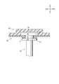
- the operating shaft 60 is displaced in the axial direction according to the deformation of the diaphragm 30.
- the operating shaft 60 is formed of a metal material having high heat resistance.
- the operation shaft 60 is disposed with the longitudinal direction thereof directed upward and downward.
- the operating shaft 60 is guided in the direction of displacement (axial direction) by the shaft guide 70.
- the operating shaft 60 has one side (upper side) connected to the plate 40 and the diaphragm 30 and the other side (lower side) passing through the atmospheric pressure chamber 22a to the outside of the casing 20 (further, the mounting formed on the mounting base 100). It extends to the lower side of the mounting base 100 via the base through hole 101.
- the other side (lower side) of the operating shaft 60 is connected to the waste gate valve 8 via a link mechanism (not shown).
- a connecting portion 61 for connecting to the plate 40 and the diaphragm 30 is provided on one side (upper side) of the operating shaft 60.
- the accommodating part 80 accommodates the shaft guide 70 inside.
- the accommodating part 80 is arrange
- the accommodating portion 80 is formed (integrally) as a part of the lower plate of the lower casing 22, but may be formed separately.
- the accommodating part 80 is formed with a metal member.
- the accommodating part 80 is formed in the substantially cylindrical shape by which the lower side was open
- a reduced diameter portion 64 having a smaller diameter than the surroundings (more specifically, the enlarged diameter portion 63 and the flange portion 65 described later) is formed.
- the diameter-reduced portion 64 is formed to have a slightly larger diameter than the through-hole 31 of the diaphragm 30 described above.
- the upper portion of the connecting portion 61 above the reduced diameter portion 64 is referred to as “expanded diameter portion 63”
- the lower portion of the reduced diameter portion 64 is referred to as “flange portion 65”.
- Such a configuration can prevent the parting line from being formed on the plate 40. That is, because the parting line is not formed on the plate 40 which is a member in contact with the diaphragm 30 (since no parting line is formed on the contact surface of the plate 40 with the diaphragm 30), the diaphragm 30 is broken by the parting line. Can be prevented.
- the enlarged diameter portion 63 and the disc portion 62 of the connecting portion 61 are disposed above the diaphragm 30. Is done. That is, the enlarged diameter portion 63 and the disc portion 62 of the connecting portion 61 are disposed in the negative pressure chamber 21 a through the diaphragm 30. The enlarged diameter portion 63 and the disc portion 62 of the connecting portion 61 are connected to the plate 40 in the negative pressure chamber 21a. Thus, the plate 40 is connected to the operating shaft 60 in a state where the plate 40 is entirely disposed in the negative pressure chamber 21a.
- the actuator 10 is A diaphragm 30 that divides the inside of the casing 20 into a negative pressure chamber 21a and an atmospheric pressure chamber 22a; A resin plate 40 provided in the negative pressure chamber 21a and in contact with the diaphragm 30; One side is connected to the plate 40 and the diaphragm 30 and the other side is extended out of the casing 20 through the atmospheric pressure chamber 22a and can be displaced in the axial direction according to the deformation of the diaphragm 30.
- An axis 60; Comprising The operating shaft 60 passes through the diaphragm 30 and is connected to the plate 40 in the negative pressure chamber 21a, whereby the plate 40 is cut off from the atmospheric pressure chamber 22a.
- the diaphragm 30 can be prevented from being broken by the parting line of the plate 40.
Landscapes
- Engineering & Computer Science (AREA)
- Physics & Mathematics (AREA)
- Fluid Mechanics (AREA)
- Mechanical Engineering (AREA)
- General Engineering & Computer Science (AREA)
- Actuator (AREA)
Abstract
L'invention porte sur un actionneur, avec lequel actionneur il est possible d'empêcher une diminution d'une résistance de plaque par hydrolyse. A cet effet, l'invention comporte : un diaphragme (30) pour diviser l'intérieur d'un boîtier (20) en une chambre de pression négative (21a) et une chambre de pression atmosphérique (22a) ; une plaque en matière plastique (40) disposée dans la chambre de pression négative (21a) de façon à être en contact avec le diaphragme (30) ; et un arbre d'actionnement (60) dont une extrémité est reliée à la plaque (40) et au diaphragme (30), et l'autre extrémité s'étend à travers la chambre de pression atmosphérique (22a) vers l'extérieur du boîtier (20), l'arbre d'actionnement (60) étant apte à un déplacement dans la direction axiale en réponse à une déformation du diaphragme (30). La plaque (40) est séparée de la chambre atmosphérique (22a) par la liaison de l'arbre d'actionnement (60) à la plaque (40) dans la chambre de pression négative (21a) par l'intermédiaire du diaphragme (30).
Priority Applications (3)
| Application Number | Priority Date | Filing Date | Title |
|---|---|---|---|
| CN201580037249.2A CN106489031B (zh) | 2014-07-10 | 2015-07-10 | 致动器 |
| DE112015003196.0T DE112015003196T5 (de) | 2014-07-10 | 2015-07-10 | Stellglied |
| US15/322,620 US10197074B2 (en) | 2014-07-10 | 2015-07-10 | Actuator |
Applications Claiming Priority (2)
| Application Number | Priority Date | Filing Date | Title |
|---|---|---|---|
| JP2014142743A JP6087322B2 (ja) | 2014-07-10 | 2014-07-10 | アクチュエータ |
| JP2014-142743 | 2014-07-10 |
Publications (1)
| Publication Number | Publication Date |
|---|---|
| WO2016006684A1 true WO2016006684A1 (fr) | 2016-01-14 |
Family
ID=55064312
Family Applications (1)
| Application Number | Title | Priority Date | Filing Date |
|---|---|---|---|
| PCT/JP2015/069898 Ceased WO2016006684A1 (fr) | 2014-07-10 | 2015-07-10 | Actionneur |
Country Status (5)
| Country | Link |
|---|---|
| US (1) | US10197074B2 (fr) |
| JP (1) | JP6087322B2 (fr) |
| CN (1) | CN106489031B (fr) |
| DE (1) | DE112015003196T5 (fr) |
| WO (1) | WO2016006684A1 (fr) |
Families Citing this family (1)
| Publication number | Priority date | Publication date | Assignee | Title |
|---|---|---|---|---|
| US11655833B1 (en) * | 2017-03-20 | 2023-05-23 | Adam Stryffeler | Variable output cylinder assembly and method of use |
Citations (2)
| Publication number | Priority date | Publication date | Assignee | Title |
|---|---|---|---|---|
| JPS59150006U (ja) * | 1983-03-28 | 1984-10-06 | カルソニックカンセイ株式会社 | アクチユエ−タ |
| JPS61103607U (fr) * | 1984-12-13 | 1986-07-01 |
Family Cites Families (10)
| Publication number | Priority date | Publication date | Assignee | Title |
|---|---|---|---|---|
| DE2942259A1 (de) * | 1979-10-19 | 1981-05-07 | Robert Bosch Gmbh, 7000 Stuttgart | Hydraulischer motor |
| JPS5663106A (en) * | 1979-10-23 | 1981-05-29 | Matsushita Electric Ind Co Ltd | Negative pressure actuator |
| JPS59150006A (ja) | 1983-02-16 | 1984-08-28 | Daido Steel Co Ltd | スクラツプ溶解方法および装置 |
| JPS61103607A (ja) | 1984-10-26 | 1986-05-22 | Sumitomo Metal Ind Ltd | 圧延材の接合方法 |
| US5249508A (en) * | 1991-03-22 | 1993-10-05 | Jidosha Denki Kogyo Kabushiki Kaisha | Actuator of diaphragm type |
| DE112008003309T5 (de) * | 2007-12-03 | 2010-10-07 | Cts Corp., Elkhart | Linearer Positionssensor |
| DE112010004761T5 (de) * | 2009-12-09 | 2012-11-29 | Cts Corporation | Antriebs- und Sensoranordnung |
| US9435630B2 (en) * | 2010-12-08 | 2016-09-06 | Cts Corporation | Actuator and linear position sensor assembly |
| JP2013167274A (ja) | 2012-02-14 | 2013-08-29 | Taiho Kogyo Co Ltd | アクチュエータ |
| CN202646217U (zh) * | 2012-07-04 | 2013-01-02 | 隆力液压机械(北京)有限公司 | 薄膜式气动执行机构 |
-
2014
- 2014-07-10 JP JP2014142743A patent/JP6087322B2/ja active Active
-
2015
- 2015-07-10 DE DE112015003196.0T patent/DE112015003196T5/de not_active Withdrawn
- 2015-07-10 US US15/322,620 patent/US10197074B2/en active Active
- 2015-07-10 CN CN201580037249.2A patent/CN106489031B/zh active Active
- 2015-07-10 WO PCT/JP2015/069898 patent/WO2016006684A1/fr not_active Ceased
Patent Citations (2)
| Publication number | Priority date | Publication date | Assignee | Title |
|---|---|---|---|---|
| JPS59150006U (ja) * | 1983-03-28 | 1984-10-06 | カルソニックカンセイ株式会社 | アクチユエ−タ |
| JPS61103607U (fr) * | 1984-12-13 | 1986-07-01 |
Also Published As
| Publication number | Publication date |
|---|---|
| JP2016017617A (ja) | 2016-02-01 |
| US10197074B2 (en) | 2019-02-05 |
| US20170152871A1 (en) | 2017-06-01 |
| CN106489031B (zh) | 2018-11-16 |
| CN106489031A (zh) | 2017-03-08 |
| JP6087322B2 (ja) | 2017-03-01 |
| DE112015003196T5 (de) | 2017-03-23 |
Similar Documents
| Publication | Publication Date | Title |
|---|---|---|
| US5722367A (en) | Engine idle speed air control | |
| WO2016136239A1 (fr) | Appareil de soupape | |
| JP5009107B2 (ja) | サックバックバルブ | |
| WO2017156831A1 (fr) | Soupape proportionnelle à gaz | |
| JP5004703B2 (ja) | 減圧弁 | |
| CN110094513A (zh) | 一种电动阀 | |
| CN109869494A (zh) | 电子膨胀阀及具有其的制冷系统 | |
| JP2017531140A (ja) | ブローオフ弁に用いられる調整機構 | |
| MX2021002370A (es) | Dispositivo de valvula. | |
| JP6087322B2 (ja) | アクチュエータ | |
| US9494254B2 (en) | Electro-magnetic valve | |
| JP6074388B2 (ja) | アクチュエータ | |
| CN110094524B (zh) | 一种电动阀 | |
| JP2013525680A (ja) | 車両エンジンのターボチャージャにおける排気ブレーキ用の制御シリンダ | |
| JP5526853B2 (ja) | ダイヤフラム型アクチュエータ | |
| JP6058592B2 (ja) | アクチュエータ | |
| CN106640388B (zh) | 发动机及其控制egr率的装置 | |
| CN103244709A (zh) | 压力调节阀 | |
| KR101671950B1 (ko) | 솔레노이드 일체형 액추에이터 | |
| JP5004702B2 (ja) | 減圧弁 | |
| JP2013167274A (ja) | アクチュエータ | |
| KR20150098009A (ko) | 터보차저 액추에이터 | |
| WO2020050221A1 (fr) | Vanne de commande de pression | |
| US6571766B2 (en) | Idle speed controller for internal combustion engine | |
| JP2016023682A (ja) | バルブ |
Legal Events
| Date | Code | Title | Description |
|---|---|---|---|
| 121 | Ep: the epo has been informed by wipo that ep was designated in this application |
Ref document number: 15818161 Country of ref document: EP Kind code of ref document: A1 |
|
| WWE | Wipo information: entry into national phase |
Ref document number: 15322620 Country of ref document: US |
|
| WWE | Wipo information: entry into national phase |
Ref document number: 112015003196 Country of ref document: DE |
|
| 122 | Ep: pct application non-entry in european phase |
Ref document number: 15818161 Country of ref document: EP Kind code of ref document: A1 |