WO2016009502A1 - Dispositif de commande de transformation par tournage et programme d'assistance de transformation par tournage - Google Patents
Dispositif de commande de transformation par tournage et programme d'assistance de transformation par tournage Download PDFInfo
- Publication number
- WO2016009502A1 WO2016009502A1 PCT/JP2014/068863 JP2014068863W WO2016009502A1 WO 2016009502 A1 WO2016009502 A1 WO 2016009502A1 JP 2014068863 W JP2014068863 W JP 2014068863W WO 2016009502 A1 WO2016009502 A1 WO 2016009502A1
- Authority
- WO
- WIPO (PCT)
- Prior art keywords
- approach angle
- turning
- processing unit
- tool
- axis
- Prior art date
- Legal status (The legal status is an assumption and is not a legal conclusion. Google has not performed a legal analysis and makes no representation as to the accuracy of the status listed.)
- Ceased
Links
Images


Classifications
-
- B—PERFORMING OPERATIONS; TRANSPORTING
- B23—MACHINE TOOLS; METAL-WORKING NOT OTHERWISE PROVIDED FOR
- B23Q—DETAILS, COMPONENTS, OR ACCESSORIES FOR MACHINE TOOLS, e.g. ARRANGEMENTS FOR COPYING OR CONTROLLING; MACHINE TOOLS IN GENERAL CHARACTERISED BY THE CONSTRUCTION OF PARTICULAR DETAILS OR COMPONENTS; COMBINATIONS OR ASSOCIATIONS OF METAL-WORKING MACHINES, NOT DIRECTED TO A PARTICULAR RESULT
- B23Q15/00—Automatic control or regulation of feed movement, cutting velocity or position of tool or work
- B23Q15/007—Automatic control or regulation of feed movement, cutting velocity or position of tool or work while the tool acts upon the workpiece
- B23Q15/14—Control or regulation of the orientation of the tool with respect to the work
-
- B—PERFORMING OPERATIONS; TRANSPORTING
- B23—MACHINE TOOLS; METAL-WORKING NOT OTHERWISE PROVIDED FOR
- B23B—TURNING; BORING
- B23B1/00—Methods for turning or working essentially requiring the use of turning-machines; Use of auxiliary equipment in connection with such methods
-
- B—PERFORMING OPERATIONS; TRANSPORTING
- B23—MACHINE TOOLS; METAL-WORKING NOT OTHERWISE PROVIDED FOR
- B23Q—DETAILS, COMPONENTS, OR ACCESSORIES FOR MACHINE TOOLS, e.g. ARRANGEMENTS FOR COPYING OR CONTROLLING; MACHINE TOOLS IN GENERAL CHARACTERISED BY THE CONSTRUCTION OF PARTICULAR DETAILS OR COMPONENTS; COMBINATIONS OR ASSOCIATIONS OF METAL-WORKING MACHINES, NOT DIRECTED TO A PARTICULAR RESULT
- B23Q15/00—Automatic control or regulation of feed movement, cutting velocity or position of tool or work
- B23Q15/20—Automatic control or regulation of feed movement, cutting velocity or position of tool or work before or after the tool acts upon the workpiece
- B23Q15/22—Control or regulation of position of tool or workpiece
- B23Q15/26—Control or regulation of position of tool or workpiece of angular position
-
- G—PHYSICS
- G05—CONTROLLING; REGULATING
- G05B—CONTROL OR REGULATING SYSTEMS IN GENERAL; FUNCTIONAL ELEMENTS OF SUCH SYSTEMS; MONITORING OR TESTING ARRANGEMENTS FOR SUCH SYSTEMS OR ELEMENTS
- G05B19/00—Program-control systems
- G05B19/02—Program-control systems electric
- G05B19/18—Numerical control [NC], i.e. automatically operating machines, in particular machine tools, e.g. in a manufacturing environment, so as to execute positioning, movement or co-ordinated operations by means of program data in numerical form
- G05B19/404—Numerical control [NC], i.e. automatically operating machines, in particular machine tools, e.g. in a manufacturing environment, so as to execute positioning, movement or co-ordinated operations by means of program data in numerical form characterised by control arrangements for compensation, e.g. for backlash, overshoot, tool offset, tool wear, temperature, machine construction errors, load, inertia
-
- G—PHYSICS
- G05—CONTROLLING; REGULATING
- G05B—CONTROL OR REGULATING SYSTEMS IN GENERAL; FUNCTIONAL ELEMENTS OF SUCH SYSTEMS; MONITORING OR TESTING ARRANGEMENTS FOR SUCH SYSTEMS OR ELEMENTS
- G05B19/00—Program-control systems
- G05B19/02—Program-control systems electric
- G05B19/18—Numerical control [NC], i.e. automatically operating machines, in particular machine tools, e.g. in a manufacturing environment, so as to execute positioning, movement or co-ordinated operations by means of program data in numerical form
- G05B19/4093—Numerical control [NC], i.e. automatically operating machines, in particular machine tools, e.g. in a manufacturing environment, so as to execute positioning, movement or co-ordinated operations by means of program data in numerical form characterised by part programming, e.g. entry of geometrical information as taken from a technical drawing, combining this with machining and material information to obtain control information, named part program, for the NC machine
- G05B19/40937—Numerical control [NC], i.e. automatically operating machines, in particular machine tools, e.g. in a manufacturing environment, so as to execute positioning, movement or co-ordinated operations by means of program data in numerical form characterised by part programming, e.g. entry of geometrical information as taken from a technical drawing, combining this with machining and material information to obtain control information, named part program, for the NC machine concerning programming of machining or material parameters, pocket machining
-
- G—PHYSICS
- G05—CONTROLLING; REGULATING
- G05B—CONTROL OR REGULATING SYSTEMS IN GENERAL; FUNCTIONAL ELEMENTS OF SUCH SYSTEMS; MONITORING OR TESTING ARRANGEMENTS FOR SUCH SYSTEMS OR ELEMENTS
- G05B2219/00—Program-control systems
- G05B2219/30—Nc systems
- G05B2219/36—Nc in input of data, input key till input tape
- G05B2219/36204—Lathe, turning
-
- G—PHYSICS
- G05—CONTROLLING; REGULATING
- G05B—CONTROL OR REGULATING SYSTEMS IN GENERAL; FUNCTIONAL ELEMENTS OF SUCH SYSTEMS; MONITORING OR TESTING ARRANGEMENTS FOR SUCH SYSTEMS OR ELEMENTS
- G05B2219/00—Program-control systems
- G05B2219/30—Nc systems
- G05B2219/37—Measurements
- G05B2219/37344—Torque, thrust, twist, machining force measurement
-
- G—PHYSICS
- G05—CONTROLLING; REGULATING
- G05B—CONTROL OR REGULATING SYSTEMS IN GENERAL; FUNCTIONAL ELEMENTS OF SUCH SYSTEMS; MONITORING OR TESTING ARRANGEMENTS FOR SUCH SYSTEMS OR ELEMENTS
- G05B2219/00—Program-control systems
- G05B2219/30—Nc systems
- G05B2219/50—Machine tool, machine tool null till machine tool work handling
- G05B2219/50282—Tool offset as function of cutting depth
-
- Y—GENERAL TAGGING OF NEW TECHNOLOGICAL DEVELOPMENTS; GENERAL TAGGING OF CROSS-SECTIONAL TECHNOLOGIES SPANNING OVER SEVERAL SECTIONS OF THE IPC; TECHNICAL SUBJECTS COVERED BY FORMER USPC CROSS-REFERENCE ART COLLECTIONS [XRACs] AND DIGESTS
- Y02—TECHNOLOGIES OR APPLICATIONS FOR MITIGATION OR ADAPTATION AGAINST CLIMATE CHANGE
- Y02P—CLIMATE CHANGE MITIGATION TECHNOLOGIES IN THE PRODUCTION OR PROCESSING OF GOODS
- Y02P90/00—Enabling technologies with a potential contribution to greenhouse gas [GHG] emissions mitigation
- Y02P90/02—Total factory control, e.g. smart factories, flexible manufacturing systems [FMS] or integrated manufacturing systems [IMS]
Definitions
- the present invention relates to a turning control device and a turning support program.
- a tool in the longitudinal direction of the workpiece (Z-axis direction) with the workpiece gripped and rotated on the lathe spindle and the tool blade cut into the workpiece in the radial direction (X-axis direction) Is known to perform turning.
- the back component force is a component in the radial direction (X-axis direction) of the cutting resistance of the workpiece, and exerts a force to bend the workpiece in the workpiece radial direction (X-axis direction). For this reason, when processing a fine shaft having a large aspect ratio, the influence of the back component force on the processing accuracy cannot be ignored.
- Patent Document 1 it has been proposed to design a tool that can reduce the back component force to zero. Specifically, based on the knowledge that one approach angle at which the back component force becomes zero is determined according to the depth of cut, a tool having an approach angle at which the back component force becomes zero when the depth of cut is set is designed. It is described.
- Patent Document 1 has a problem that it is difficult to give the tool versatility because a new tool needs to be designed each time the cutting depth changes.
- the present invention has been made in view of such circumstances, and its purpose is to provide a turning control device capable of providing versatility to a tool used for turning while maintaining high accuracy of turning a workpiece. And providing a turning support program.
- a spindle that grips and rotates a workpiece, a tool holding unit that grips a tool for turning the workpiece, a Z axis direction that is parallel to the rotation axis of the spindle, and the spindle and the spindle
- a Z-axis driving unit for displacing at least one of the tool holding units
- an X-axis driving unit for displacing at least one of the main shaft and the tool holding unit in the X-axis direction orthogonal to the Z-axis
- a turning apparatus provided with a B-axis drive unit that rotates the tool holding unit around a Y-axis orthogonal to both the X-axis, the workpiece gripped by the main shaft is rotated, and the X
- a turning control device that performs turning by relatively feeding the tool in at least the Z-axis direction in a state where a predetermined cut amount is cut in the axial direction
- a command value for setting an approach angle command value that defines an approach angle that is an angle formed by a direction perpendicular to a feed direction of the tool relative to the workpiece and the blade portion of the tool when performing the turning process A setting processing unit, an approach angle setting command amount calculation unit that calculates a B axis command amount for controlling the approach angle to be the approach angle command value based on the tool shape data, as an approach angle setting command amount;
- a turning control device comprising: a command processing unit that outputs the approach angle setting command amount to the B-axis drive unit.
- an approach angle command value is set, a B-axis command amount for controlling the approach angle at the time of machining to be the approach angle command value is calculated, and output to the B-axis drive unit to The approach angle can be changed as appropriate.
- the approach angle By changing the approach angle, the back force applied to the workpiece by the tool can be changed. As a result, the back force can be reduced to zero or extremely small by adjusting the approach angle during turning. it can. Therefore, even if a special tool is not used, turning accuracy can be extremely increased by using a general-purpose tool with an appropriate approach angle command value set.
- the storage unit further stores tool data indicating a cutting edge position of the tool when the tool is gripped by the tool holding unit, and the approach angle setting command amount is based on the tool data.
- a compensation amount calculation processing unit that calculates an approach angle compensation amount that compensates for a displacement in the XZ plane from the blade tip position before setting the approach angle command value of the blade tip position when performing B-axis turning positioning; and the command processing unit includes: The turning according to the technical idea 1, wherein the X-axis command amount and the Z-axis command amount output from the machining program processing unit are corrected with an approach angle compensation amount and output to the X-axis drive unit and the Z-axis drive unit. Processing control device.
- the cutting edge position is displaced in the XZ plane.
- Technical idea 3 An instruction to change the approach angle command value set by the command value setting processing unit is received after the start of the turning process and before the completion, and the approach angle is based on the received instruction.
- An angle adjustment acceptance processing unit that changes a command value, and the command processing unit calculates the approach angle setting command amount corresponding to the changed approach angle command value calculated by the approach angle setting command amount calculation processing unit,
- the turning control device according to the technical idea 1 which is output to the B-axis drive unit.
- the approach angle at the time of turning can be changed after the start of turning and before completion, so when chatter is detected during turning, the approach angle command value is set on the spot. It is possible to suppress chatter by changing, and it is possible to easily make changes that improve the accuracy of turning.
- the tool edge position changes in the X-axis direction and the Z-axis direction according to the distance between the tool edge position and the B-axis turning center. For this reason, it is difficult to change the approach angle during turning. Therefore, in the above apparatus, since turning is interrupted when an instruction to change the approach angle is received, the cutting edge can be moved away from the workpiece by manual operation during the interruption. By moving away from the workpiece, even if the cutting edge of the tool changes in the X-axis direction and the Z-axis direction, it does not interfere with the workpiece, and as a result, the approach angle command value can be easily changed.
- the machining program includes approach angle data for determining an approach angle at the time of machining, and the command value setting processing unit sets approach angle data of the machining program to the approach angle command value.
- An approach angle command value storage processing unit that receives a command for registering the approach angle command value changed by the angle adjustment reception processing unit in the machining program, and the approach angle command value storage processing unit stores the command in the machining program.
- the approach angle command value storage processing unit when the approach angle command value storage processing unit is provided, when the approach angle command value received by the angle adjustment reception processing unit is an appropriate value, it can be registered in the machining program.
- the storage unit further stores tool data indicating a cutting edge position of the tool when the tool is gripped by the tool holding unit, and the angle adjustment reception processing unit changes the approach angle command value.
- an operation compensation amount that compensates for a displacement in the XZ plane of the blade tip position from the blade tip position of the immediately preceding B-axis position when the B-axis turning positioning is performed with the approach angle setting command amount is calculated.
- the technical processing unit 4 includes a compensation amount calculation processing unit, and the command processing unit outputs the approach angle setting command amount and the motion compensation amount simultaneously to the B-axis driving unit, the X-axis driving unit, and the Z-axis driving unit. Turning control device.
- the cutting edge position changes due to the positional relationship between the B-axis turning center and the cutting edge on the XZ plane.
- the above apparatus calculates the X-axis motion compensation amount and the Z-axis motion compensation amount for canceling the displacement from the immediately preceding blade edge position, and outputs it simultaneously with the approach angle setting command amount. Even if the angle command value is variously changed, the approach angle can be changed without changing the blade position.
- the machining program includes a cutting amount data for determining a cutting amount and approach angle data for determining the approach angle, and the back force applied to the workpiece by the tool when the turning is performed.
- An approach angle calculation processing unit that calculates an approach angle at which an absolute value is equal to or less than a specified value, the approach angle calculation processing unit registers the calculated approach angle as approach angle data in the machining program, and the command value setting process.
- the approach angle calculation processing unit calculates the approach angle at which the back force generated during turning is less than the specified value, so it does not have information on the approach angle that can reduce the back force. Even an operator can perform turning that can reduce the back force.
- Technical idea 8 Based on the approach angle command value set by the command value setting processing unit and the tool shape data, a determination processing unit that determines whether the turning is possible, and the determination processing unit
- the turning control device comprising a notification processing unit for notifying that the turning is not possible.
- work can be determined based on an approach angle command value and a tool shape, and it can be judged that turning cannot be performed, or can notify that.
- Technical idea 9 A turning support program that causes a computer to execute each processing unit in the turning control device according to any one of technical ideas 1 to 8.
- Technical idea 10 a spindle that grips and rotates a workpiece, a tool holding unit that grips a tool for turning the workpiece, a Z axis direction that is parallel to the rotation axis of the spindle, and the spindle and the spindle A Z-axis driving unit for displacing at least one of the tool holding units; an X-axis driving unit for displacing at least one of the main shaft and the tool holding unit in the X-axis direction orthogonal to the Z-axis; Using a turning apparatus provided with a B-axis drive unit that rotates and positions the tool holding unit around the Y-axis orthogonal to both the X-axis, the workpiece gripped by the main shaft is rotated, In a turning control method that performs turning by sending the tool relatively at least in the Z-axis direction with a predetermined cut amount
- Approach angle setting command amount calculation processing step for calculating the B axis command amount for controlling the approach angle command value as the approach angle setting command amount, and outputting the approach angle setting command amount to the B axis drive unit A turning processing control method comprising:
- the system block diagram concerning one Embodiment The perspective view which shows the partial structure of the turning apparatus concerning the embodiment.
- (A) shows the tool shape data concerning the embodiment
- (b) shows the definition of tool shape data
- (c) is a figure which shows the definition of a nose radius.
- (A) And (b) is a figure which shows back component force data concerning the embodiment.
- Functional block diagram of a turning support program The functional block diagram relevant to the control processing at the time of turning processing in a prior art.
- the flowchart which shows the procedure of the setting process of the approach angle data concerning the embodiment The flowchart which shows the process sequence of the approach angle calculation process part M16.
- (A) And (b) is a figure which shows the judgment method of the presence or absence of the interference generation
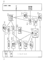
- a turning system 20 shown in FIG. 1 is a combined machining lathe system for turning a workpiece 10.
- the turning system 20 includes a turning device 30, a turning control device 50, and an interface 70.
- the turning apparatus 30 includes a spindle 12 that grips the workpiece 10, a tool 36 that is a tool, and a tool holding unit 14 that grips the tool 36.
- the main shaft 12 can rotate around the rotation axis ax1.
- the cutting tool 36 includes an insert 32 that functions as a blade portion for turning the workpiece 10 and a shank 34 that supports the insert 32.
- FIG. 2 shows a partial configuration of the turning apparatus 30 that holds the workpiece 10.
- the turning apparatus 30 further includes a tool post 16 that is provided with a tool holding portion 14 so as to be capable of turning.
- the tool post 16 can be linearly displaced in the Z-axis direction parallel to the rotation axis ax1 and in the X-axis direction orthogonal to the Z-axis.
- the tool holding portion 14 is installed so as to be able to turn around a turning axis ax2 that is parallel to the Y axis orthogonal to both the Z axis and the X axis and passes through the B axis turning center P1 on the tool post 16. Yes.
- the main shaft 12, the tool holding unit 14, and the tool post 16 are driven by each driving unit shown in FIG.
- the turning device 30 shown in FIG. 1 includes a main shaft drive unit 40 that rotates the main shaft 12 around the rotation axis ax1.
- the turning apparatus 30 includes an X-axis drive unit 42 that displaces the tool post 16 in the X-axis direction, and a Z-axis drive unit 44 that displaces the tool post 16 in the Z-axis direction.
- the turning apparatus 30 includes a B-axis drive unit 46 that turns and positions the tool holding unit 14 with the turning axis ax2 as a turning center.
- the B-axis drive unit 46 drives the B-axis of the tool holding unit 14, and the B-axis is described as “B” in FIGS. 1 and 2.
- the turning control device 50 is a control device that controls the turning device 30 to perform turning. Specifically, the turning control device 50 calculates each command amount of the main shaft drive unit 40, the X-axis drive unit 42, the Z-axis drive unit 44, and the B-axis drive unit 46 of the turning device 30, and the main shaft drive unit 40, the X-axis drive unit 42, the Z-axis drive unit 44, and the B-axis drive unit 46, respectively.
- the command amount of the spindle drive unit 40 is the rotational speed of the spindle 12.
- the command amount of the X-axis drive unit 42 is the amount of displacement of the tool post 16 in the X-axis direction.
- the command amount of the Z-axis drive unit 44 is the amount of displacement of the tool post 16 in the Z-axis direction. Further, the command amount of the B-axis drive unit 46 is a turning angle of the tool holding unit 14 with the turning axis line ax2 being the turning center.
- the turning control device 50 includes a central processing unit (CPU) 52 that performs various arithmetic processes and a memory 54.
- the memory 54 stores tool shape data 60, tool data 62, a machining program 64, a turning support program 66, and back component force data 68. Further, an approach angle command value 58 for determining an approach angle at the time of turning is provided as an internal variable.
- the tool shape data 60 includes information on the edge angle ⁇ , the reference cutting angle ⁇ , and the nose radius R for each piece of identification information (tool No.) specifying each tool. It is data.
- FIG. 3B shows the cutting edge angle ⁇ and the reference cutting angle ⁇ .
- the cutting edge angle ⁇ is the angle of the cutting edge P2 of the insert 32.
- the reference cutting angle ⁇ is a parameter for specifying the shape of the blade portion (main cutting blade portion 32b) on the traveling direction side of the insert 32.
- the reference cutting angle ⁇ is an angle formed between the main cutting edge portion 32b of the insert 32 and the axis of the workpiece when the shank 34 of the cutting tool 36 is opposed in a posture orthogonal to the axis of the workpiece.
- the straight line L indicates a straight line parallel to the axis of the workpiece.
- This posture of the cutting tool 36 is a posture when the tool holding portion 14 is positioned at the B-axis origin.
- the B-axis origin is the B-axis position when the cutting tool 36 mounted on the tool holding unit 14 is parallel to the X-axis direction and faces the workpiece, and the cutting tool 36 is in the same direction as the direction of the tool holding unit 14. It shall be installed.
- Fig. 3 (c) shows the nose radius R.
- the nose radius R is a radius of curvature that defines the shape of the cutting edge P2 of the insert 32.
- the clearance angle ⁇ is also shown.
- the clearance angle ⁇ is an angle formed by the clearance surface of the insert 32 (back surface with respect to the traveling direction) and the finished surface of the workpiece. Incidentally, it is assumed that the cutting tool 36 originally uses the tool holder 14 at the B-axis origin.
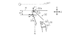
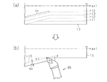
- FIG. 4 shows the approach angle ⁇ and the cutting depth ap.
- the cutting tool 36 is illustrated, and an enlarged part of the insert 32 of the cutting tool 36 is illustrated.
- the approach angle ⁇ is an angle formed by a main cutting edge portion 32b and a direction N (for example, the X-axis direction) orthogonal to the feed direction M (for example, the Z-axis direction) of the cutting tool 36.
- the positive direction of the approach angle ⁇ is the side that rotates counterclockwise from the direction N.
- FIG. 4 also shows the cutting amount ap of the workpiece 10. In this embodiment, the cutting amount ap is set to a value larger than the nose radius R.
- the back component force F1 applied to the workpiece 10 by the tip 32a of the insert 32 and the back component force F2 applied to the workpiece 10 by the main cutting edge portion 32b are opposite to each other.
- the back component force F2 can be adjusted by the approach angle ⁇ , and the back component force F2 can be made equal to the back component force F1.
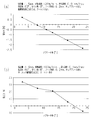
- FIG. 5 (a) and FIG. 5 (b) exemplify data obtained by experimentally determining the relationship between the approach angle and the back component force when turning with a predetermined cutting amount using a specific tool.
- the back component force during turning can be made zero by appropriately determining the approach angle.
- the approach angle at the time of turning can be changed by positioning the tool holding part 14 holding the tool in the B-axis turning, and the B-axis angle of the tool holding part 14 can be set to an appropriate angle for turning. By doing so, the back force can be made zero.
- the machining program 64 is a data group that defines how the workpiece 10 is turned.
- the machining program 64 is a data group necessary for machining including data indicating a machining shape and data indicating machining conditions such as the approach angle ⁇ and the cutting depth ap described above.
- turning is performed by cutting a tool by a predetermined cutting amount in the X-axis direction, that is, the workpiece radial direction, and sending the tool in a direction including at least the Z-axis direction.
- the feed direction includes so-called taper machining, in which the feed direction is also slightly fed in the X-axis direction.
- the tool data 62 is data indicating the cutting edge position of the tool. As shown in FIG. 6, here, the data indicating the coordinate value of the cutting edge P2 of the insert 32 when the tool holding portion 14 holding the cutting tool 36 is positioned at the B-axis origin, with reference to the B-axis turning center P1; To do. The process using the tool data will be described later.
- the interface 70 shown in FIG. 1 includes a display unit 72 and an input unit 74.
- the display part 72 is for notifying an operator of various information through vision.
- the input unit 74 is a target on which an input operation is performed by the operator, whereby the operator can transmit a request to the turning control device 50.
- the tool shape data 60, the tool data 62, the machining program 64, and the back component force data 68 can be input by an input operation of the input unit 74.
- a part of data included in the machining program 64 can be automatically generated by the turning control device 50.
- the tool data 62 can also be automatically measured using a sensor that detects the edge position.
- the back component force data 68 shown in FIG. 1 is data used by the turning control device 50 to calculate the approach angle ⁇ that makes the back component force applied to the workpiece 10 zero during turning.
- FIG. 7 shows back component force data 68.
- the back component force data 68 is data obtained by experimentally determining the relationship between the approach angle ⁇ and the back component force applied to the workpiece 10 for each cutting amount ap.
- the back component force data for each depth of cut ap differs depending on the material of the workpiece 10, the cutting speed, the feed speed, the presence or absence of the insert breaker of the insert 32, and whether or not the coolant is used during turning. Therefore, strictly speaking, it is necessary to experimentally obtain the relationship between the approach angle and the back component force as shown in FIG.
- FIG. 8 shows functional blocks realized by the CPU 52 executing the turning support program 66 shown in FIG.
- This functional block is realized by modifying the functional block when the machining program is executed in the conventional general cutting control device shown in FIG.
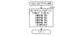
- the machining program processing unit M22 analyzes the machining program 64 and the tool data 62 with reference to the machining program 64 and the tool data 62, and sends the command amount of each axis for each machining operation to the turning machine 30. Sequential output is performed to perform machining operations.
- the machining program processing unit M22 in the present embodiment has the same function as the conventional one and calculates and outputs a command amount for each axis for executing the machining program, but the output destination is different from the conventional technique.
- the command value setting processing unit M24 sets the approach angle command value 58.
- the approach angle calculation processing unit M16 calculates an approach angle ⁇ at which the back component force becomes zero based on the back component force data 68, and registers it in the machining program 64 as approach angle data.
- the approach angle data or the approach angle command value 58 set by the command value setting processing unit M24 is a value that can be turned without causing interference between the workpiece and the tool. Judge whether or not.
- the notification processing unit M20 outputs a message to that effect to the display unit 72.
- the angle adjustment acceptance processing unit M28 When the angle adjustment acceptance processing unit M28 accepts an approach angle change request from the operator during execution of the machining program 64, the angle adjustment acceptance processing unit M28 outputs a feed stop command to the turning device 30 to interrupt the turning, and then sets the command value.
- the B-axis positioning angle is changed by changing the approach angle command value 58 set by the processing unit M24.
- the approach angle command value storage processing unit M32 registers the changed approach angle command value 58 in the machining program 64 as approach angle data.
- the approach angle setting command amount calculation processing unit M26 calculates a B-axis command amount that realizes the set or changed approach angle command value 58 as the approach angle setting command amount, and the compensation amount calculation processing unit M30 holds the tool.
- the approach angle compensation amount that cancels out the displacement of the cutting edge position caused by positioning the part 14 by the B-axis turning command amount by the approach angle setting command amount and the approach angle command value 58 changed by the angle adjustment acceptance processing unit M28. Then, an operation compensation amount that cancels out the displacement of the cutting edge position that occurs when the B-axis slightly turns is calculated.
- the command processing unit M34 outputs the approach angle setting command amount and the motion compensation amount to the turning device 30, and the command amount of the X-axis drive unit 42 for turning, which is the output of the machining program processing unit M22.
- the command amount of the Z-axis drive unit 44 is corrected with the approach angle compensation amount and output to the turning device 30.
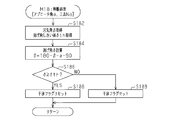
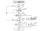
- FIG. 10 shows a procedure for setting approach angle data for a turning program, which is mainly performed by the approach angle calculation processing unit M16, the determination processing unit M18, and the notification processing unit M20. This process is realized by the CPU 52 executing the turning support program 66.
- the CPU 52 starts this process when a request for setting the approach angle data is generated.
- the approach angle data can be input by selecting either automatic setting of approach angle data using the back component force data 68 or an input operation of approach angle data by the operator. Therefore, the CPU 52 first determines whether or not it is a request for automatic setting of approach angle data (S12). If the CPU 52 determines that the request is an automatic setting request (S12: YES), the CPU 52 starts processing of the approach angle calculation processing unit M16 (S14).
- FIG. 11 shows details of processing of the approach angle calculation processing unit M16.
- the CPU 52 acquires the machining program 64, and acquires the cutting amount data and the tool No. of the tool to be used from the machining program 64 (S142). Subsequently, the CPU 52 obtains back component force data 68 composed of a plurality of data obtained by experimentally determining the relationship between the approach angle ⁇ and the back component force, and one data among the plurality of data is stored in the machining program 64. A selection is made based on the cutting amount data and the tool No. of the tool used (S144). In this data, the approach angle ⁇ at which the back component force becomes zero is determined (S146) and registered as approach angle data in the machining program 64 (S148).
- step S12 of FIG. 10 the CPU 52 accepts that the approach angle ⁇ is input via the input unit 74, and processes the input approach angle ⁇ . Registration in the program 64 (S28).
- the CPU 52 determines whether or not interference between the byte 36 and the workpiece 10 does not occur when the approach angle data thus manually or automatically registered is actually applied to the control by the determination processing unit M18 ( S18).
- FIG. 12 shows details of the processing of the determination processing unit M18.
- the CPU 52 passes the approach angle ⁇ and the tool No as arguments when calling the determination processing unit M18, acquires the cutting edge angle ⁇ and the clearance angle threshold ⁇ th of the designated tool No (S182), and calculates the clearance angle ⁇ . (S184).
- the threshold value ⁇ th defines a gap between the cutting tool 36 and the workpiece, and is preferably set to a positive value close to zero that is equal to or greater than zero.
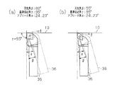
- FIG. 13 shows an example of this determination process.
- FIG. 13A shows a case where the cutting edge angle ⁇ is 80 °, the reference cutting angle ⁇ is 95 °, and the approach angle ⁇ is “24.23 °”.
- the clearance angle ⁇ is “ ⁇ 14.23 °” according to Equation 1, which is a value smaller than zero. 36 interferes with the workpiece 10. For this reason, in this case, it is determined that turning cannot be performed.
- FIG. 13A shows a case where the cutting edge angle ⁇ is 80 °, the reference cutting angle ⁇ is 95 °, and the approach angle ⁇
- 13B shows a case where the blade edge angle ⁇ is 55 °, the reference cutting angle ⁇ is 95 °, and the approach angle ⁇ is “24.23 °”.
- the clearance angle ⁇ becomes “10.77 °”, which is a value larger than zero, according to Equation 1, 36 does not interfere with the workpiece 10. Therefore, in this case, it is determined that turning can be performed.
- step S186 in FIG. 12 the CPU 52 determines whether or not the calculated clearance angle ⁇ is equal to or larger than the clearance angle threshold ⁇ th in order to determine the interference between the cutting tool 36 and the workpiece 10.
- the clearance angle ⁇ is less than the threshold value ⁇ th (S186: NO)
- it is determined that there is interference between the cutting tool 36 and the workpiece 10 and the processing of the determination processing unit M18 is performed with an interference flag.
- the process ends (S189).
- the CPU 52 determines that the clearance angle ⁇ is equal to or larger than the threshold value ⁇ th (S186: YES)
- the CPU 52 determines that no interference occurs and ends the processing of the determination processing unit M18 without an interference flag ( S188).
- the CPU 52 determines the presence or absence of interference in step S19 in FIG. 10, and when there is interference, that is, when the interference flag is set (S19: YES), the notification processing unit M20 displays the display unit. The fact is output to 72, and the operator is notified that the workpiece and the tool interfere (S22).
- FIG. 14 shows a command value setting processing unit M24, an approach angle setting command amount calculation processing unit M26, a compensation amount calculation processing unit M30, a determination processing unit M18, a notification processing unit M20, a machining program processing unit M22, a command processing unit M34, and The procedure of the turning process according to the present embodiment performed mainly by the approach angle command value storage processing unit M32 will be described. This process is realized by the CPU 52 executing the turning support program 66.
- the CPU 52 acquires the machining program 64 (S30), and sets the approach angle data in the machining program to the approach angle command value 58 in the command value setting processing unit M24 (S31). Subsequently, the approach angle setting command amount calculation processing unit M26 is called to calculate a B-axis command amount for controlling the approach angle ⁇ to the approach angle command value 58 (step S32).
- this B-axis command amount is referred to as an approach angle setting command amount ⁇ (see FIG. 13 ⁇ ).
- the approach angle setting command amount ⁇ is calculated based on the approach angle command value 58 (“ ⁇ d ” is used in the following equation) and the reference cutting angle ⁇ .
- the approach angle ⁇ can be controlled to be the approach angle command value 58 ( ⁇ d ).
- ⁇ obtained by this equation 3 is the approach angle setting command amount ⁇ .
- the approach angle ⁇ when the tool holding unit 14 is at the B-axis origin is “5 °” in both FIGS. 13A and 13B from Equation 2.
- the approach angle setting command amount ⁇ for setting this to “24.23 °” of the approach angle command value 58 ( ⁇ d ) is “19.23 °” from Equation 3. That is, the commanded approach angle “24.23 °” can be realized by turning and positioning the B-axis by “19.23 °”.
- the approach angle setting command amount ⁇ is determined by the reference cutting angle ⁇ and the approach angle command value 58 ( ⁇ d ) of the tool shape data 60.
- the B axis swiveling of the tool holder 14 is performed.
- the cutting edge P2 of the cutting tool 36 is displaced in the X-axis direction and the Z-axis direction according to the distance between the center P1 and the cutting edge P2 of the cutting tool 36 held by the tool holding unit 14.
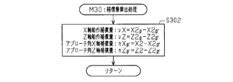
- step S ⁇ b> 33 the CPU 52 calls the compensation amount calculation processing unit M ⁇ b> 30 and calculates the approach angle compensation amount based on the tool data 62.
- the compensation amount calculation processing unit M ⁇ b> 30 calculates the approach angle compensation amount based on the tool data 62.
- FIG. 6 shows the positional relationship between the blade edge P2 and the B-axis turning center P1.
- the coordinate value of the cutting edge P2 of the tool based on the B-axis turning center P1 is registered before machining.
- [P1] is the position of the B-axis turning center P1
- [P2] is the position of the tool edge P2 of the tool at the B-axis origin
- [P2] ⁇ is the approach angle setting command amount ⁇ of the tool holder 14 Only the position of the cutting edge P2 of the tool when the B-axis swivel positioning is shown.
- L1 is the length between the cutting edge P2 and the B-axis turning center P1
- ⁇ is when the tool holder 14 is positioned at the B-axis origin. This is the B-axis angular position of the blade tip P2.
- FIG. 15 shows the processing procedure of the compensation amount calculation processing unit M30.
- the X-axis motion compensation amount ⁇ X and Z-axis described in detail in the description of the approach angle manual fine adjustment function shown in FIG. 18 described later.
- a calculation formula of the motion compensation amount ⁇ Z is also described.
- the approach angle compensation amount is added to the machining command amount processed without taking the approach angle into consideration and outputting it, the displacement caused by the B-axis turning positioning by the approach angle setting command amount ⁇ is corrected. be able to.
- the CPU 52 confirms whether or not the acquired machining program 64 can be normally operated.
- the CPU 52 calls the determination processing unit M18 in step S34 to confirm whether or not there is interference between the bit 36 and the workpiece 10. To do.
- This process because only in the arguments to be passed to the contents explained in FIG. 12 is an approach angle command value alpha d is different, description thereof will be omitted.
- the CPU 52 determines whether or not the cutting tool 36 is found to interfere with the workpiece 10 during the turning process by the processing of the determination processing unit M18 (S35), and when determining that it interferes (S35: YES), to that effect. Is output to the display unit 72 (S36) to notify the operator that the workpiece and the tool interfere with each other.
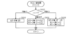
- the CPU 52 calls the command processing unit M34 (S37).
- the CPU 52 outputs the approach angle setting command amount ⁇ calculated by the approach angle setting command amount calculation processing unit M26 to the B-axis drive unit 46 of the turning apparatus 30 by the process shown in FIG. 16 (S804). Thereafter, the CPU 52 repeats the processes of steps S40 and S41 in FIG. 14 until the data of the machining program 64 is completed.
- the spindle that grips the workpiece is rotated to a specified rotational speed, or the tool to be used is determined and positioned at a rapid feed to the machining start position. After machining, a series of procedures are programmed until the tool post is returned to the machine origin, the spindle rotation is stopped, and the process is finished.
- the CPU 52 calls the machining program processing unit M22 in step S40, and calculates and outputs a command amount for executing turning according to the machining program 64 for each machining operation (FIG. 17: S402). Subsequently, the command processing unit M34 is called (S41).
- CPU 52 is processed by the processing shown in FIG.
- the compensation amount calculation unit M30 approach angle X-axis compensation amount ItaX phi advance calculated in step 33, and the approach angle Z-axis compensation amount? Z phi It adds to the command amount of the X-axis and Z-axis output from the program processing part M22, and outputs it (S806).
- Chatter may occur due to the back force during the turning process, and the operator who notices it can easily change the approach angle command value 58 ( ⁇ d ) and the B-axis swivel positioning of the tool holder 14 accordingly.
- the function to fine-tune the approach angle manually is prepared so that it can be performed.
- FIG. 18 illustrates an approach angle change process in the approach angle manual fine adjustment function mainly performed by the angle adjustment reception processing unit M28, the approach angle setting command amount calculation processing unit M26, the compensation amount calculation processing unit M30, and the command processing unit M34. Show the procedure. This process is realized by the CPU 52 executing the turning support program 66.
- FIG. 19 shows details of the angle adjustment acceptance processing unit M28.
- a feed stop command is output to the turning device 30, the feed of the cutting tool 36 in the Z-axis direction is stopped, and the machining is temporarily interrupted (S604).
- the CPU 52 determines whether there is an instruction to change the approach angle command value 58 ( ⁇ d ) through an input operation on the input unit 74 (S606), or whether there is an instruction to resume machining (S608).
- the instruction to change the approach angle command value 58 ( ⁇ d ) may be realized by providing the input unit 74 with a hand pulse.
- the hand pulse is an interface that is manually rotated by the operator, and a pulse having a pulse number corresponding to the rotation operation amount is output, and the approach angle command value 58 ( ⁇ d ) is changed according to the output pulse number.
- an instruction value for the correction angle may be actually input as a numerical value to the input unit 74.
- the processing resumption instruction may be used also as a normal automatic operation start switch.
- the CPU 52 determines that there is an instruction to change the approach angle command value 58 ( ⁇ d ) (S606: YES)
- the CPU 52 accepts the change instruction input to the input unit 74 and receives the approach angle command value 58 ( ⁇ d ⁇ ⁇ d).
- ') Is updated (S612).
- the value before update is described as “ ⁇ d ”
- the value after update is described as “ ⁇ d ′”.
- the “accepted” flag is set, and the processing of M28 is terminated (S614). If it is determined that there is an instruction to resume processing (S608: YES), the “accepted” flag is reset and the process of M28 is terminated (S610).
- the approach angle manual fine adjustment function can be used as many times as necessary until the machining is restarted after the switch for turning on the approach angle command value 58 ( ⁇ d ) is turned on and the machining is stopped. Since the command value 58 ( ⁇ d ) can be changed, the process includes a step S602 for determining whether or not the process is an initial process.
- step S62 in FIG. 18 the CPU 52 determines whether or not a change instruction has been received during the angle adjustment reception process, and determines that there is a reception, that is, if the “acceptance” flag is set.
- the CPU 52 calls the compensation amount calculation processing unit M30 (S68).
- the compensation amount calculation processing unit M30 in addition to the calculation of the approach angle compensation amount already described, the cutting edge by turning the tool holding unit 14 based on the B axis based on the change amount of the approach angle command value changed by the approach angle manual fine adjustment function An operation compensation amount that compensates for the displacement of P2 on the XZ plane is also calculated.
- the X-axis direction component and the Z-axis direction component of the motion compensation amount are referred to as an X-axis motion compensation amount and a Z-axis motion compensation amount, respectively.
- FIG. 15 briefly describes the equations, but X2 ⁇ , Z2 ⁇ , and X2 ⁇ ′ and Z2 ⁇ ′ are the tool data (X2, Z2) and the previous approach angle from Equation 4 to Equation 21, respectively.
- the setting command amount ⁇ and the approach angle setting command amount ⁇ ′ after manual operation can be obtained.
- the CPU 52 calls the command processing unit M34 shown in FIG. 16 (S72).
- the approach angle setting command amount ⁇ ′ calculated in step S64 (( ⁇ ′ ⁇ ) as the B-axis displacement amount), the X-axis motion compensation amount ⁇ X and the Z-axis motion compensation amount calculated in step S68.
- ⁇ Z is simultaneously output to the B-axis drive unit 46, the X-axis drive unit 42, and the Z-axis drive unit 44 of the turning apparatus 30 (S808).
- the approach angle ⁇ can be changed without changing the X-axis coordinate value and the Z-axis coordinate value of the cutting edge P2.
- the main cutting edge portion 32b of the tool may bite into the workpiece by turning the B axis, but since the rotation of the main shaft is not stopped, only a small amount of cutting is performed. Don't be.
- the command processing unit M34 has a function of outputting a command amount to each drive unit 40, 42, 44, 46 of the turning device 30.
- the command processing unit M34 is called (S37, S41, S72)
- the process of the command processing unit M34 is switched by passing the command code as an argument (S802).
- the command codes are easy to understand, and are described as “B axis output”, “correction output”, and “manual output”.
- step S62 in FIG. 18 When it is determined in step S62 in FIG. 18 that there is no reception, that is, when the “acceptance” flag is reset (S62: NO), the machining program stopped by the angle adjustment reception processing unit M28. Execution is resumed (S74), and the processing of the approach angle manual fine adjustment function is finished.
- steps S40 and S41 in FIG. 14 is performed by the processing in FIG. 18 by approach angle command value 58 ( ⁇ d ′), approach angle setting command amount ⁇ ′, approach angle X-axis compensation amount ⁇ X ⁇ ′ , and approach.
- the angle Z axis compensation amount ⁇ Z ⁇ ′ is corrected and restarted. That is, the subsequent turning is performed with the approach angle command value 58 ( ⁇ d ′) finely adjusted manually.
- the CPU 52 calls the approach angle command value storage processing unit M32 (S42). That is, it is determined whether or not the approach angle has been changed by the operation of FIG. 20 (S422). If the CPU 52 determines that the approach angle has been changed (S422: YES), the CPU 52 determines whether an operation for updating the approach angle data in the machining program 64 has been performed by an input operation on the input unit 74. (S424).
- the CPU 52 displays a message “Do you want to register the changed approach angle in the machining program?” On the display unit 72.
- the CPU 52 determines that an instruction to update the approach angle data in the machining program 64 has been issued (S424: YES), and the approach in the machining program 64 is determined.
- the angle data is updated to the currently set approach angle command value 58 ( ⁇ d ′) (S426). That is, the approach angle command value 58 ( ⁇ d ′) finally used in the current turning process is registered as approach angle data in the machining program 64.
- chatter when chatter occurs, the operator interrupts the turning process and instructs to change the approach angle command value 58 ( ⁇ d ). Then, when turning according to the change is made and chatter is improved, an operation for updating the approach angle data in the machining program 64 to the approach angle command value 58 ( ⁇ d ′) is performed, thereby performing the subsequent work.
- the approach angle command value 58 ( ⁇ d ′) updated to 10 machining is continuously adopted. For this reason, when machining a plurality of workpieces 10 having the same specification, once chatter does not occur, chatter does not occur in subsequent machining. Further, by effectively using this function, even when there is no data in the back component force data 68 that perfectly matches the current machining conditions, the approach angle ⁇ at which chatter does not occur is found relatively quickly. This makes it possible to quickly achieve chatter-free turning.
- the command value setting processing unit M24 sets the approach angle command value 58 ( ⁇ d ) using the parameter data defined as the approach angle data. Further, the approach angle calculation processing unit M16 sets approach angle data at which the obtained back component force becomes zero in the parameter data.
- the approach angle at which the back component force F1 and the back component force F2 shown in FIG. 4 are equal is physically calculated. It may be calculated by
- FIG. 21 shows a turning example in which factors other than the clearance angle ⁇ should be considered.
- FIG. 21A shows an example of turning by moving the cutting tool 36 in the order of four machining routes rt1, rt2, rt3, and rt4.
- the final shape indicated by the machining route rt4 has a tapered portion TP.
- the cutting amount in the taper portion TP is changed in the initial stage of turning (machining routes rt1, rt2). Thereby, the cutting amount ap can be fixed in the taper portion TP in the later stage of the turning process (machining routes rt3, rt4).
- FIG. 21B shows a point in time when the taper portion TP is reached in the processing route rt3.
- the cutting amount ap is defined as the length in the direction orthogonal to the relative feed direction of the cutting tool 36 with respect to the workpiece 10.
- the approach angle ⁇ is an angle formed by the main cutting edge portion 32b with respect to a direction orthogonal to the relative feed direction.
- the clearance angle ⁇ is “90 ⁇ ”, but at the end of the taper portion TP, the clearance angle ⁇ is larger than zero.
- the cutting tool 36 can interfere with a part of the workpiece 10 other than the taper part TP. Therefore, it is desirable to determine the presence or absence of interference depending on whether or not a value “(90 ⁇ ) ⁇ ” obtained by subtracting the taper angle ⁇ from the clearance angle ⁇ is equal to or larger than the clearance angle threshold value ⁇ th. .
- the depth of cut ap at the taper portion TP can be fixed in the later stage of the turning process (machining routes rt3 and rt4) in which the machining diameter is likely to become a problem and the machining force is reduced.
- the approach angle ⁇ corresponding to the depth of cut ap can be set in the later stage of the turning process in which the back force tends to be a problem, and thus the influence of the back force is suitable from the shape of the work 10 after turning. Can be suppressed.
- the approach angle ⁇ is changed in a state where the feed during machining is stopped and the cutting edge of the tool is in contact with the workpiece. That is, the X-axis motion compensation amount and the Z-axis motion compensation amount are calculated in addition to the approach angle setting command amount ⁇ , and the approach angle can be changed without changing the cutting edge position by outputting these simultaneously. Not limited to. For example, when the machining is stopped, the cutting tool 36 may be greatly displaced in the X-axis direction so that the cutting tool 36 is once pulled away from the workpiece 10.
- the cutting tool 36 is swiveled in the B-axis direction, and the cutting tool 36 is moved in the direction opposite to the displacement in the X-axis direction and the Z-axis direction due to the swiveling positioning.
- the turning process may be resumed.
- the position at which machining is interrupted is stored, and a path from the position at the time of resuming turning to the stored machining interrupt position may be automatically inserted.
- the approach angle ⁇ changing process is not limited to the process performed with the tool post 16 stopped.
- the approach angle ⁇ may be changed in a state where the tool post 16 is moved in the Z-axis direction.
- processing for canceling the Z-axis motion compensation amount may be performed in the feed processing in the Z-axis direction.
- the present invention is not limited to an input operation performed by the operator via the input unit 74.
- an apparatus for detecting chatter may be provided, and an interruption instruction or an instruction to change the approach angle may be output from this apparatus.
- a device for detecting chatter for example, a device that receives sound or vibration as input and determines that chatter has occurred when a predetermined frequency noise exceeds a threshold value may be used.
- the present invention is not limited to this, and a workpiece that is being turned may be photographed, and chatter may be detected as a result of image analysis.
- a device that includes a sensor that detects a load applied to the tool and detects chatter based on an output value of the sensor may be used.
- the back component force data 68 can be sequentially updated.
- an instruction to change the approach angle by a predetermined amount ⁇ in the positive (negative) direction is issued. If chatter is not suppressed as a result, negative (positive) is given.
- a device that issues an instruction to change the direction by a predetermined amount ⁇ may be used. In this case, if chatter is suppressed but not yet sufficiently suppressed, an instruction to change the predetermined amount ⁇ in the same direction may be issued.
- the first cutting amount is set in the first turning process
- the second cutting amount is set in the second turning process.
- the turning support program is not limited to a program incorporated in a turning control device that realizes all of the processes of FIGS.
- a program for supporting the operation of a turning apparatus capable of displacing the cutting tool 36 in the X-axis direction and the Z-axis direction and swing-positioning with the swing axis line ax2 as a swing center FIG. Only the processing of FIG. 14 may be realized. In this case, that is, even when there is no approach angle manual fine adjustment function performed by the angle adjustment reception processing unit M28, when chatter occurs during turning by the set approach angle command value 58 ( ⁇ d ), By inputting the approach angle ⁇ in the process of step S28 of FIG. 10, the approach angle command value 58 ( ⁇ d ) can be finely adjusted by directly rewriting the approach angle data in the machining program.
- a drive unit for displacing the main shaft 12 in the Z-axis direction may be provided instead of providing the Z-axis drive unit 44 for displacing the tool post 16 in the Z-axis direction.
- a drive unit for displacing the main shaft 12 in the Z-axis direction may be provided instead of including the X-axis drive unit 42 that displaces the tool holding unit 14 in the X-axis direction.
- the cutting tool is not limited to one in which the insert and the shank are separated from each other, and may be formed integrally.
- the notification is not limited to visual information, and may be performed by sound, for example.
- the X-axis command amount and the Z-axis command amount output from the machining program processing unit are not limited to those in which the turning program is executed by the command processing unit correcting and outputting the approach angle compensation amount.
- the tool data indicating the cutting edge position may be corrected with the approach angle compensation amount.
- the machining program processing shown in FIG. 17 calculates the X-axis command amount and the Z-axis command amount based on the tool data corrected with the approach angle compensation amount, the processing for correcting these with the approach angle compensation amount is performed. It can be deleted from the command processing unit.
Landscapes
- Engineering & Computer Science (AREA)
- Physics & Mathematics (AREA)
- Mechanical Engineering (AREA)
- Human Computer Interaction (AREA)
- Manufacturing & Machinery (AREA)
- General Physics & Mathematics (AREA)
- Automation & Control Theory (AREA)
- Geometry (AREA)
- Numerical Control (AREA)
- Turning (AREA)
Abstract
L'invention est caractérisée en ce que, lorsqu'une profondeur de coupe est désignée via une unité (74) d'entrée, un dispositif (50) de commande de transformation par tournage calcule un angle d'approche qui annule l'effort de poussée d'après des données d'effort de poussée. Lorsque l'angle d'approche est ainsi calculé, le dispositif (50) de commande de transformation par tournage délivre à une unité (46) de variateur d'axe B une quantité de consigne telle qu'un outil (36) de coupe soit positionné en subissant une rotation autour d'un point (P1). Le dispositif (50) de commande de transformation par tournage délivre également, d'après la profondeur de coupe et l'angle d'approche, une quantité de consigne servant à réguler la profondeur de coupe à une unité (42) de variateur d'axe X servant à déplacer linéairement l'outil (36) de coupe dans une direction d'axe X. Ensuite, une transformation par tournage est effectuée en faisant déplacer l'outil (36) de coupe dans une direction d'axe Z par une unité (44) de variateur d'axe Z en fonction d'une vitesse de coupe tandis qu'une pièce (10) est mise en rotation par une unité (40) de variateur d'axe principal.
Priority Applications (5)
| Application Number | Priority Date | Filing Date | Title |
|---|---|---|---|
| CN201480040279.4A CN105378570B (zh) | 2014-07-16 | 2014-07-16 | 车削加工控制装置 |
| EP14894814.4A EP3001264B1 (fr) | 2014-07-16 | 2014-07-16 | Dispositif de commande de transformation par tournage et programme d'assistance de transformation par tournage |
| JP2015505752A JP5766895B1 (ja) | 2014-07-16 | 2014-07-16 | 旋削加工制御装置、および旋削加工支援プログラム |
| PCT/JP2014/068863 WO2016009502A1 (fr) | 2014-07-16 | 2014-07-16 | Dispositif de commande de transformation par tournage et programme d'assistance de transformation par tournage |
| US14/963,243 US9873174B2 (en) | 2014-07-16 | 2015-12-09 | Turning controller |
Applications Claiming Priority (1)
| Application Number | Priority Date | Filing Date | Title |
|---|---|---|---|
| PCT/JP2014/068863 WO2016009502A1 (fr) | 2014-07-16 | 2014-07-16 | Dispositif de commande de transformation par tournage et programme d'assistance de transformation par tournage |
Related Child Applications (1)
| Application Number | Title | Priority Date | Filing Date |
|---|---|---|---|
| US14/963,243 Continuation US9873174B2 (en) | 2014-07-16 | 2015-12-09 | Turning controller |
Publications (1)
| Publication Number | Publication Date |
|---|---|
| WO2016009502A1 true WO2016009502A1 (fr) | 2016-01-21 |
Family
ID=53888035
Family Applications (1)
| Application Number | Title | Priority Date | Filing Date |
|---|---|---|---|
| PCT/JP2014/068863 Ceased WO2016009502A1 (fr) | 2014-07-16 | 2014-07-16 | Dispositif de commande de transformation par tournage et programme d'assistance de transformation par tournage |
Country Status (5)
| Country | Link |
|---|---|
| US (1) | US9873174B2 (fr) |
| EP (1) | EP3001264B1 (fr) |
| JP (1) | JP5766895B1 (fr) |
| CN (1) | CN105378570B (fr) |
| WO (1) | WO2016009502A1 (fr) |
Cited By (4)
| Publication number | Priority date | Publication date | Assignee | Title |
|---|---|---|---|---|
| CN107436586A (zh) * | 2017-09-20 | 2017-12-05 | 张家港沙工科技服务有限公司 | 一种切削机床用控制软件 |
| KR20200135943A (ko) * | 2018-03-30 | 2020-12-04 | 시티즌 도케이 가부시키가이샤 | 공작 기계 |
| JPWO2022024975A1 (fr) * | 2020-07-30 | 2022-02-03 | ||
| US12090593B2 (en) * | 2020-10-05 | 2024-09-17 | Fanuc Corporation | Control device |
Families Citing this family (17)
| Publication number | Priority date | Publication date | Assignee | Title |
|---|---|---|---|---|
| JP6576758B2 (ja) * | 2015-09-18 | 2019-09-18 | シチズン時計株式会社 | 切削装置及びその制御方法 |
| JP6881725B2 (ja) * | 2016-05-27 | 2021-06-02 | 中村留精密工業株式会社 | ワーク加工方法、主軸角度補正装置及び複合旋盤 |
| WO2018011990A1 (fr) * | 2016-07-15 | 2018-01-18 | 株式会社牧野フライス製作所 | Dispositif de génération de programme d'usinage et procédé d'usinage |
| JP6946104B2 (ja) * | 2017-08-01 | 2021-10-06 | オークマ株式会社 | 工作機械における工具切込方向の制御装置及び制御方法 |
| EP3702853B1 (fr) | 2019-03-01 | 2025-05-21 | AB Sandvik Coromant | Procédé de génération de données de commande de contrôle pour commander un tour cnc |
| EP3702854A1 (fr) | 2019-03-01 | 2020-09-02 | AB Sandvik Coromant | Procédé de génération de données de commande de contrôle pour commander une tour cnc |
| CN111890123B (zh) * | 2019-05-06 | 2022-02-08 | 四川大学 | 一种刀具前刀面轴向倾角在机检测计算方法 |
| JP7748037B2 (ja) * | 2019-08-30 | 2025-10-02 | ファナック株式会社 | 数値制御装置 |
| JP7460763B2 (ja) * | 2020-05-08 | 2024-04-02 | ファナック株式会社 | ワークに予め形成された凹部に内面加工する加工工具の移動を制御する数値制御装置及び数値制御方法 |
| JP6843313B1 (ja) * | 2020-06-03 | 2021-03-17 | 三菱電機株式会社 | 制御システム |
| US12517489B2 (en) * | 2020-07-10 | 2026-01-06 | Fanuc Corporation | Control device and control method for machine tool, and slave shaft control device |
| DE112021003993T5 (de) * | 2020-07-30 | 2023-05-11 | Fanuc Corporation | Numerische Steuereinrichtung und Steuerungsverfahren |
| JP7516234B2 (ja) * | 2020-12-10 | 2024-07-16 | オークマ株式会社 | ワークの旋削加工方法及び工作機械 |
| JPWO2023127539A1 (fr) * | 2021-12-27 | 2023-07-06 | ||
| CN114871846B (zh) * | 2022-06-16 | 2024-01-23 | 广东今科机床有限公司 | 一种智能车削加工控制方法及控制系统 |
| EP4371684A1 (fr) * | 2022-11-18 | 2024-05-22 | CERATIZIT Austria Gesellschaft m.b.H. | Procédé de tournage |
| CN118617472A (zh) * | 2024-06-06 | 2024-09-10 | 深圳市浩能科技有限公司 | 一种可调分切装置及调刀方法 |
Citations (7)
| Publication number | Priority date | Publication date | Assignee | Title |
|---|---|---|---|---|
| JP2001328002A (ja) * | 2000-05-22 | 2001-11-27 | Yamazaki Mazak Corp | 工作機械 |
| JP2002154034A (ja) * | 2000-11-17 | 2002-05-28 | Nakamura Tome Precision Ind Co Ltd | 工作機械における工具刃先位置の設定方法 |
| JP2002187003A (ja) * | 2000-12-21 | 2002-07-02 | Mori Seiki Co Ltd | 切削工機の制御装置及びその表示方法 |
| JP2009113143A (ja) | 2007-11-05 | 2009-05-28 | Univ Nihon | 切削工具の形状設計方法及び形状設計システム |
| JP2009538744A (ja) * | 2006-05-29 | 2009-11-12 | シーメンス アクチエンゲゼルシヤフト | 旋削加工を制御する方法、および旋削加工に適したnc機械 |
| WO2012057207A1 (fr) * | 2010-10-27 | 2012-05-03 | 三菱重工業株式会社 | Procédé de maintien de la qualité de coupe, et dispositif de maintien de la qualité de coupe |
| JP2014087878A (ja) * | 2012-10-30 | 2014-05-15 | Nihon Univ | 放電加工機 |
Family Cites Families (9)
| Publication number | Priority date | Publication date | Assignee | Title |
|---|---|---|---|---|
| JPH07214416A (ja) * | 1994-02-02 | 1995-08-15 | Toyota Motor Corp | ターンブローチ加工方法及び装置 |
| DE19846426A1 (de) * | 1998-10-08 | 2000-04-13 | Open Mind Software Technologie | Verfahren zum Steuern der Arbeitsbewegung eines Werkzeugs zur materialabtragenden Bearbeitung eines Materialblocks |
| JP2003039201A (ja) * | 2001-07-30 | 2003-02-12 | Nissan Motor Co Ltd | 切削加工装置および切削加工方法 |
| US7853351B2 (en) * | 2002-02-21 | 2010-12-14 | Gary John Corey | CNC machine tool and integrated machine tool controller incorporating 3D and up to 8-axes real time interactive tool compensation |
| JP5024846B2 (ja) | 2005-05-16 | 2012-09-12 | 学校法人日本大学 | 切削工具 |
| JP4622873B2 (ja) * | 2006-01-27 | 2011-02-02 | 株式会社日立プラントテクノロジー | Ncプログラムの作成方法及びプログラム |
| WO2012167360A1 (fr) | 2011-06-07 | 2012-12-13 | Parker Grant Leonard | Outil rotatif autopropulsé |
| EP2915614B1 (fr) * | 2012-10-31 | 2020-09-02 | Makino Milling Machine Co., Ltd. | Dispositif de commande de machine-outil et machine-outil |
| CN103522348B (zh) * | 2013-10-18 | 2015-10-21 | 清华大学 | 对刀方法及其真圆加工方法与菲涅尔透镜加工方法 |
-
2014
- 2014-07-16 WO PCT/JP2014/068863 patent/WO2016009502A1/fr not_active Ceased
- 2014-07-16 JP JP2015505752A patent/JP5766895B1/ja active Active
- 2014-07-16 CN CN201480040279.4A patent/CN105378570B/zh active Active
- 2014-07-16 EP EP14894814.4A patent/EP3001264B1/fr not_active Revoked
-
2015
- 2015-12-09 US US14/963,243 patent/US9873174B2/en active Active
Patent Citations (7)
| Publication number | Priority date | Publication date | Assignee | Title |
|---|---|---|---|---|
| JP2001328002A (ja) * | 2000-05-22 | 2001-11-27 | Yamazaki Mazak Corp | 工作機械 |
| JP2002154034A (ja) * | 2000-11-17 | 2002-05-28 | Nakamura Tome Precision Ind Co Ltd | 工作機械における工具刃先位置の設定方法 |
| JP2002187003A (ja) * | 2000-12-21 | 2002-07-02 | Mori Seiki Co Ltd | 切削工機の制御装置及びその表示方法 |
| JP2009538744A (ja) * | 2006-05-29 | 2009-11-12 | シーメンス アクチエンゲゼルシヤフト | 旋削加工を制御する方法、および旋削加工に適したnc機械 |
| JP2009113143A (ja) | 2007-11-05 | 2009-05-28 | Univ Nihon | 切削工具の形状設計方法及び形状設計システム |
| WO2012057207A1 (fr) * | 2010-10-27 | 2012-05-03 | 三菱重工業株式会社 | Procédé de maintien de la qualité de coupe, et dispositif de maintien de la qualité de coupe |
| JP2014087878A (ja) * | 2012-10-30 | 2014-05-15 | Nihon Univ | 放電加工機 |
Non-Patent Citations (1)
| Title |
|---|
| See also references of EP3001264A4 * |
Cited By (10)
| Publication number | Priority date | Publication date | Assignee | Title |
|---|---|---|---|---|
| CN107436586A (zh) * | 2017-09-20 | 2017-12-05 | 张家港沙工科技服务有限公司 | 一种切削机床用控制软件 |
| KR20200135943A (ko) * | 2018-03-30 | 2020-12-04 | 시티즌 도케이 가부시키가이샤 | 공작 기계 |
| JPWO2019188220A1 (ja) * | 2018-03-30 | 2021-04-01 | シチズン時計株式会社 | 工作機械 |
| JP7195305B2 (ja) | 2018-03-30 | 2022-12-23 | シチズン時計株式会社 | 工作機械 |
| KR102602751B1 (ko) * | 2018-03-30 | 2023-11-15 | 시티즌 도케이 가부시키가이샤 | 공작 기계 |
| JPWO2022024975A1 (fr) * | 2020-07-30 | 2022-02-03 | ||
| WO2022024975A1 (fr) * | 2020-07-30 | 2022-02-03 | ファナック株式会社 | Dispositif de commande numérique et procédé de commande |
| JP7436678B2 (ja) | 2020-07-30 | 2024-02-22 | ファナック株式会社 | 数値制御装置、及び制御方法 |
| US12541188B2 (en) | 2020-07-30 | 2026-02-03 | Fanuc Corporation | Numerical controller and control method |
| US12090593B2 (en) * | 2020-10-05 | 2024-09-17 | Fanuc Corporation | Control device |
Also Published As
| Publication number | Publication date |
|---|---|
| EP3001264B1 (fr) | 2018-01-10 |
| EP3001264A4 (fr) | 2016-11-09 |
| CN105378570B (zh) | 2017-02-22 |
| CN105378570A (zh) | 2016-03-02 |
| US9873174B2 (en) | 2018-01-23 |
| JPWO2016009502A1 (ja) | 2017-04-27 |
| EP3001264A1 (fr) | 2016-03-30 |
| US20160089760A1 (en) | 2016-03-31 |
| JP5766895B1 (ja) | 2015-08-19 |
Similar Documents
| Publication | Publication Date | Title |
|---|---|---|
| JP5766895B1 (ja) | 旋削加工制御装置、および旋削加工支援プログラム | |
| JP5836511B1 (ja) | 旋削加工制御装置 | |
| US9760079B2 (en) | Cutting tool machining method and a wire electric discharge machine | |
| US9815194B2 (en) | Force control robot and method for controlling same | |
| JP6359847B2 (ja) | 干渉回避装置 | |
| TW200817117A (en) | Lathe, computer program for lathe control, and machining method by lathe | |
| TW201317727A (zh) | 數值控制裝置 | |
| WO2020110251A1 (fr) | Dispositif et procédé de commande numérique, et dispositif d'apprentissage machine | |
| WO2012101789A1 (fr) | Dispositif de commande numérique | |
| KR0180953B1 (ko) | 수치제어 공작기계의 주축법선방향 제어방법 및 장치 | |
| US11559851B2 (en) | Laser machining device and laser machining method | |
| US10994422B2 (en) | Robot system for adjusting operation parameters | |
| JP4531023B2 (ja) | クランクシャフトの加工方法、クランクシャフトの加工装置、制御装置およびプログラム | |
| JP3665344B2 (ja) | ロボットのジョグ操作方法及びロボットのジョグ操作システム | |
| CN109789555B (zh) | 机器人系统及其运转方法 | |
| WO2021230203A1 (fr) | Système de mesure d'outil et procédé de commande | |
| JP2017124485A (ja) | 工作機械および工具先端位置の補正方法 | |
| JP2018018294A (ja) | 数値制御装置および工具の移動制御方法 | |
| JP2010039993A (ja) | Nc旋盤の制御方法及び制御装置 | |
| JP2017087376A (ja) | ワーク搬送システム | |
| JP2001328087A (ja) | 加工用ロボットのオフライン教示システム | |
| JP5946680B2 (ja) | アーク溶接用プログラムのプログラム変換方法、及びアーク溶接用プログラムのプログラム変換装置 | |
| JPH09123038A (ja) | 加工装置 | |
| JP2005199358A (ja) | ワイヤカット放電加工方法、ワイヤカット放電加工制御方法およびワイヤカット放電加工装置 | |
| EP2781297A1 (fr) | Procédé de fabrication de joint et dispositif de fabrication apparenté |
Legal Events
| Date | Code | Title | Description |
|---|---|---|---|
| ENP | Entry into the national phase |
Ref document number: 2015505752 Country of ref document: JP Kind code of ref document: A |
|
| WWE | Wipo information: entry into national phase |
Ref document number: 2014894814 Country of ref document: EP |
|
| 121 | Ep: the epo has been informed by wipo that ep was designated in this application |
Ref document number: 14894814 Country of ref document: EP Kind code of ref document: A1 |
|
| NENP | Non-entry into the national phase |
Ref country code: DE |