WO2016035545A1 - Moissonneuse - Google Patents
Moissonneuse Download PDFInfo
- Publication number
- WO2016035545A1 WO2016035545A1 PCT/JP2015/073127 JP2015073127W WO2016035545A1 WO 2016035545 A1 WO2016035545 A1 WO 2016035545A1 JP 2015073127 W JP2015073127 W JP 2015073127W WO 2016035545 A1 WO2016035545 A1 WO 2016035545A1
- Authority
- WO
- WIPO (PCT)
- Prior art keywords
- harvesting
- feeder
- frame
- rear wall
- communication port
- Prior art date
- Legal status (The legal status is an assumption and is not a legal conclusion. Google has not performed a legal analysis and makes no representation as to the accuracy of the status listed.)
- Ceased
Links
Images













Classifications
-
- A—HUMAN NECESSITIES
- A01—AGRICULTURE; FORESTRY; ANIMAL HUSBANDRY; HUNTING; TRAPPING; FISHING
- A01D—HARVESTING; MOWING
- A01D57/00—Delivering mechanisms for harvesters or mowers
-
- A—HUMAN NECESSITIES
- A01—AGRICULTURE; FORESTRY; ANIMAL HUSBANDRY; HUNTING; TRAPPING; FISHING
- A01D—HARVESTING; MOWING
- A01D61/00—Elevators or conveyors for binders or combines
-
- A—HUMAN NECESSITIES
- A01—AGRICULTURE; FORESTRY; ANIMAL HUSBANDRY; HUNTING; TRAPPING; FISHING
- A01D—HARVESTING; MOWING
- A01D67/00—Undercarriages or frames specially adapted for harvesters or mowers; Mechanisms for adjusting the frame; Platforms
Definitions
- the present invention relates to a harvesting machine provided with a harvesting unit that harvests crops to be planted in a field.
- the harvester includes a harvesting unit that harvests crops to be planted in a field, and a communication port that is connected to the harvesting unit and that is harvested in the harvesting unit, formed on the rear wall of the harvesting unit (in Patent Document 1). And a feeder for receiving it through the "connection opening” and transporting it backwards.
- the support structure for supporting the harvesting part on the feeder side is located within the lateral width of the harvesting part communication port (within the lateral width of the feeder).
- JP 2013-183680 A Japanese Unexamined Patent Publication No. 2013-183680 (JP 2013-183680 A) ([Fig. 6], [Fig.7])
- the feeder is often connected to a portion biased to the left or right side of the left and right center of the harvesting section. If the harvesting part is supported on the feeder side by the support structure located within the left and right width of the communication port of the harvesting part as in the past, the weight balance of the harvesting part on the left and right sides of the feeder will be unbalanced.
- the frame structure of the harvesting section and feeder is likely to be loaded, and there are concerns regarding durability. For this reason, there is room for improvement in the support structure that supports the harvesting portion on the feeder side.
- the characteristic configuration of the harvester according to the present invention includes a harvesting unit that harvests a crop to be planted in a field, and a crop that is connected to the harvesting unit and is harvested in the harvesting unit is formed on a rear wall of the harvesting unit.
- a feeder that receives and communicates rearward through the communication port, and a lateral side portion of the harvesting portion in the lateral direction of the machine body from the communication port is supported by a support unit connected to the feeder. There is in point.
- the location where the communication port is located in the rear wall of the harvesting section is connected to the feeder, and the lateral side location in the lateral direction of the machine body is connected to the feeder from the communication port of the rear wall of the harvesting portion. It is supported by the supported part.
- the support range of the harvesting part in the left-right direction with respect to the left-right width of the harvesting part becomes sufficiently wide, and the harvesting part can be supported in a balanced manner on the left and right. Therefore, an excessive load is not easily applied to the harvester and the frame structure of the feeder, and a structure having excellent durability can be obtained. Therefore, according to the present invention, the harvesting section can be suitably supported on the feeder side.
- the support portion is provided with a lower frame that connects a lower side of the feeder and a lower side of the harvesting portion.
- the lower frame of the feeder and the lower part of the harvesting unit are connected by the lower frame of the support part on the feeder side, so that the lower part of the feeder and the lower part of the harvesting unit are connected.
- Strength can be increased.
- the support portion is provided with an upper side connecting portion connected to the upper side of the harvesting portion, and a first frame connecting the upper side connecting portion and the lower frame. It is.
- the connection strength between the feeder and the upper side of the harvesting part can be increased. Furthermore, since the upper side connecting portion and the lower frame are connected by the first frame of the feeder side support portion, a structure having high strength can be obtained.
- the upper side connecting part is provided with a mounting part for mounting and supporting the upper frame of the harvesting part, and a second frame for connecting the mounting part and the outer surface of the feeder is provided. It is preferable that
- the mounting portion of the upper side connecting portion and the outer surface of the feeder are connected by the second frame, a structure having high strength can be obtained. And since the upper frame of the harvesting part is mounted and supported on the mounting part, the upper frame of the harvesting part can be stably supported by the mounting part.
- a lower side connecting portion connected to a lower side of the harvesting portion is provided at a tip of the lower frame, and a connecting member for connecting the lower side connecting portion and the upper side connecting portion is provided. It is preferable that
- the lower side connecting portion provided at the tip of the lower frame is connected to the lower side of the harvesting portion, the lower side of the feeder and the lower side of the harvesting portion can be suitably connected.
- the lower part connection part connected with the lower part side of a harvesting part and the upper part connection part are connected with a connection member, it can be set as a structure which has high intensity
- a bottom frame of the feeder is provided, the bottom frame is extended to the outside of the feeder, and a hydraulic cylinder for raising and lowering the lower frame and the harvesting unit is connected to the bottom frame. It is preferable that
- the lower frame of the feeder-side support part and the hydraulic cylinder for raising and lowering the harvesting part are extended to the extension part extending to the outside of the feeder among the bottom frame provided at the bottom part of the feeder.
- the bottom frame serves as a member that is also used as a support structure for the harvesting portion and a support structure for the hydraulic cylinder, so that the configuration can be simplified.
- an opening different from the communication port is formed in a lateral side portion of the rear wall in the left-right direction of the airframe from the communication port, and the support portion enters the opening in the rear side. It is preferable that it is connected to a wall.
- the support portion on the feeder side is inserted into the opening formed in the lateral side position in the lateral direction of the aircraft from the communication port in the rear wall of the harvesting portion, and the rear wall and the support portion are connected. is doing. Therefore, the rear wall of the harvesting portion is stably supported by the support portion on the feeder side.
- Another characteristic configuration of the harvester according to the present invention includes a harvesting unit that harvests a crop to be planted in a field, and a crop that is connected to the harvesting unit and is harvested in the harvesting unit on a rear wall of the harvesting unit.
- a feeder for receiving and conveying rearward through the formed communication port, and an opening different from the communication port is provided in a lateral side portion of the rear wall in the left-right direction of the machine body from the communication port.
- the first connecting part formed on the lateral outer side of the feeder is connected to the harvesting part, and the first connecting part is connected to the rear wall in a state of entering the opening. is there.
- the location where the communication port is located in the rear wall of the harvesting portion is connected to the feeder, and is formed in the lateral side portion in the left-right direction of the machine body from the communication port of the rear wall of the harvesting portion.
- a location where the opening is located is connected to a first connecting portion provided outside the feeder.
- the first connecting part is connected to the rear wall of the harvesting part in a state of entering the opening, the rear wall of the harvesting part can be stably supported from below by the first connecting part. Therefore, according to the present invention, the harvesting section can be suitably supported on the feeder side.
- the first connecting part penetrates the opening and enters the harvesting part.
- the 1st connection part penetrates the opening formed in the rear wall and enters the inside of the harvesting part, the location where the opening is located in the rear wall by the first connection part Is supported in a wide range, and the harvesting part can be stably supported by the first connecting part.
- an upper member extending in the left-right direction of the fuselage is provided on an upper portion of the rear wall, and the first connecting portion is provided with a placement portion that places the upper member through the opening, It is preferable that a locking portion that extends upward from the mounting portion and that can be locked to the front surface of the upper member is provided.
- the upper member extends along the left-right direction of the fuselage in the upper portion of the rear wall, and the mounting portion that penetrates the opening of the first connecting portion supports the upper member from below, and the first connecting portion Of these, a locking portion extending upward from the placement portion can be locked to the front surface of the upper member. That is, since the upper member is supported from below by the mounting portion and the movement of the upper member in the front-rear direction is restricted by the locking portion, the harvesting portion can be supported in a stable posture.
- the first connecting portion is provided with a closing portion that closes the opening.
- the opening leading to the outside of the harvesting section is blocked by the blocking section of the first connecting section, so that the harvested crop does not leak out from the opening in the harvesting section and prevents the occurrence of harvest loss. it can.
- the feeder is provided with a second connecting portion that enters the communication port and is connected to the rear wall.
- the second connecting portion since the second connecting portion is connected to the rear wall of the harvesting portion while entering the communication port, the second connecting portion can stably support the rear wall of the harvesting portion from below.
- the feeder is connected to a portion of the rear wall that is biased to the left or right side from the left-right center of the harvesting portion, and the first connection portion is the other of the rear wall on the left and right sides of the communication port.
- the second connection portion is connected to a portion of the rear wall that is biased to the left or right side from the center of the communication port.
- the harvesting part connects with the 1st connection part connected to the location located in the other side of the rear wall on the left and right sides of the communication port, and the rear wall connected to the location biased to the left and right sides from the left and right center of the communication port
- the harvesting part can be supported in a wide range in the left-right direction by the second connecting part.
- the first connecting portion supports a portion of the rear wall that is closer to the left and right center of the harvesting portion than the communication port, the vicinity of the center of gravity of the harvesting portion is supported, and the harvesting portion can be supported in a balanced manner. .
- a drive shaft that transmits a driving force to the harvesting portion is passed behind the rear wall, and the first connecting portion is preferably arranged so as to bypass the rear side of the drive shaft. It is. *
- the first connecting portion has a structure that bypasses the rear side of the drive shaft that transmits the driving force to the harvesting portion, and therefore, special processing such as interposing a universal joint on the drive shaft side. Even if it does not perform, it becomes a simple structure where a 1st connection part and a drive shaft do not interfere, and the assembly
- a lower portion of the first connecting portion is supported by a bottom portion of the feeder.
- the lower part of the first connecting part can be favorably supported using the structure of the bottom part of the feeder.
- a horizontal frame extending from the bottom to the lateral side of the machine body, one end connected to the machine body side and the other end connected to the harvesting part side, and a hydraulic cylinder for raising and lowering the harvesting part are provided, It is preferable that the lower portion of the first connecting portion is connected to the horizontal frame and the other end of the hydraulic cylinder is connected.
- the first connecting part on the feeder side and the hydraulic cylinder for raising and lowering the harvesting part are connected to a horizontal frame extending from the bottom of the feeder to the lateral side of the machine body. That is, the horizontal frame becomes a member that is also used as a support structure for the harvesting portion and a support structure for the hydraulic cylinder, and the configuration can be simplified.
- the hydraulic cylinder is connected to a portion of the horizontal frame between the feeder and the first connecting portion in the horizontal direction of the body.
- the hydraulic cylinder is connected to a portion of the horizontal frame between the feeder and the first connecting portion, the hydraulic cylinder is moved closer to the feeder side and arranged in a compact manner in the left-right direction of the machine body. Can do.
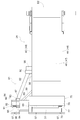
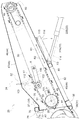
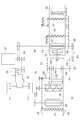
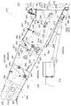
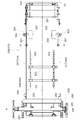
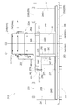
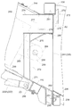
- FIG. 12 It is a figure which shows 1st Embodiment of a harvesting machine (following, it is the same also to FIG. 12), and is the whole left side view which shows the whole straw input type combine as an example of a harvesting machine. It is a whole top view which shows the whole throwing type combine. It is a rear view which shows the pre-processing apparatus of a cutting part. It is a top view which shows a feeder. It is a right view which shows the periphery of a feeder. It is a right view which shows the periphery of a support part. It is a top view which shows the pre-processing apparatus and feeder of a cutting part. It is a left view which shows the internal structure of a feeder.
- FIGS. FIG. 1 and FIG. 2 show a whole straw input type combine (an example of “harvesting machine”) for harvesting crops such as rice, wheat, and soybeans.
- This full throw-in type combine is provided with a self-propelled traveling machine body in which a body frame 12 is supported on the upper part of a pair of left and right crawler traveling apparatuses 11.
- the whole wheat throw type combine harvester stores a harvesting header section 13 for harvesting and transporting a crop to be planted in a field, a threshing device 14 for threshing the whole harvested crop, and storing the grain after the threshing process.
- a grain tank 15, an unloader 16 for discharging grains stored in the grain tank 15 to the outside of the machine, a driving unit 17 on which a driver gets on and performs a driving operation, and the like are provided.
- the driving unit 17 is located on the front right side of the traveling aircraft.
- the driver 17 is provided with a driver seat 18 on which a driver sits, various operation levers 19 and the like.
- the Glen tank 15 is located on the rear side of the operation unit 17.
- the threshing device 14 is located on the left side of the Glen tank 15.
- the threshing device 14 and the Glen tank 15 are arranged in a state of being lined up on the left and right.
- a driving engine 21 is provided below the operation unit 17. That is, the engine 21 is located on the right side of the traveling machine body, and the threshing device 14 is located on the left side of the traveling machine body.
- the harvesting header portion 13 is connected to the front side of the traveling machine body so as to be movable up and down. Specifically, the harvesting header portion 13 can swing around a lifting axis P that is directed to the left and right with respect to the machine body frame 12 by expansion and contraction of a lifting cylinder 22 formed of a hydraulic cylinder.
- the harvesting header unit 13 is configured to be movable up and down around the lifting axis P between a descending work state in which the harvesting operation is performed and an ascending non-working state in which the harvesting operation is not performed.
- the harvesting header unit 13 includes a harvesting unit 23 (an example of a “harvest unit”) that harvests and harvests crops to be planted in the field, and a feeder 24 that conveys the crops harvested by the harvesting unit 23 toward the threshing device 14. And are provided.
- a harvesting unit 23 an example of a “harvest unit”
- a feeder 24 that conveys the crops harvested by the harvesting unit 23 toward the threshing device 14. And are provided.
- a pair of left and right dividers 25 that separate the planted cereals into the harvested planted potatoes and the non-harvested planted cereals, and the harvested planted cocoons are scraped toward the rear.
- a rotary reel 26 to be cut, a clipper-shaped cutting blade 27 for cutting the planted side of the planted culm to be harvested, and harvested crops cut by the cutting blade 27 are gathered to a predetermined position on the center side in the left-right direction and rearward
- a lateral feed auger 28 that feeds out is provided.
- the cutting unit 23 is provided with a pretreatment frame body 29 that supports the divider 25, the rotary reel 26, the cutting blade 27, and the lateral feed auger 28.
- the pretreatment frame body 29 includes a bottom plate portion 30 located at the bottom, a rear wall 31 located on the rear side of the bottom plate portion 30, and a bottom plate portion 30 and a rear wall 31.
- a pair of left and right vertical side plates 32 located at both lateral ends are provided.
- the lateral feed auger 28 includes a support shaft 33 supported by the left and right side plate portions 32, a rotary drum 34 supported rotatably around the axis of the support shaft 33, and A spiral blade 35 erected on the outer periphery of the rotating drum 34 and a scraping body 36 that scrapes the harvested crop toward the feeder 24 at the rear of the machine body are provided.
- the harvested crop is collected to the left and right central sides by the spiral blades 35 by rotationally driving the rotary drum 34, and moved to the feeder 24 side by the scraper 36 that moves around the rotary drum 34 and moves back and forth from the rotary drum 34. Sent.
- the cutting unit 23 has a lateral width (harvest width) larger than the distance between the lateral outer left end of the threshing device 14 and the lateral lateral right end of the grain tank 15 in the lateral direction of the machine body.
- the width is wider than that of the traveling aircraft. That is, the cutting part 23 has a left-right width larger than the distance between the lateral outer ends of the left and right crawler type traveling devices 11.
- the right lateral outer end portion of the cutting blade 27 of the cutting unit 23 is located on the right lateral outer side with respect to the right lateral outer end portion of the right crawler type traveling device 11.
- the left lateral outside of the cutting blade 27 of the cutting unit 23 is located on the left lateral outer side with respect to the left lateral outer end of the left crawler type traveling device 11. That is, the left and right crawler type traveling devices 11 are located on the inner side in the lateral direction with respect to the region where the planted crop is cut by the cutting unit 23. Thereby, the harvesting of the planted crops by the cutting unit 23 can be efficiently performed, and a step margin of the crawler type traveling device 11 is widely secured in the lateral direction at the lateral outer side of the crawler type traveling device 11. It is difficult for the unmanned crop to be trampled by the traveling device 11.
- the rear wall 31 of the pretreatment frame body 29 of the cutting unit 23 has an upper horizontal frame 37 (corresponding to an “upper frame”) extending in the left-right direction and extending in the left-right direction.
- a lower horizontal frame 38, a plurality of vertical frames 39 extending in the up-down direction, a plurality of vertical rear surface plates 40, and a plurality of horizontal frames 41 extending in the left-right direction are provided.
- the upper horizontal frame 37 and the lower horizontal frame 38 are located at the rear of the cutting unit 23.
- the upper horizontal frame 37 and the lower horizontal frame 38 are each configured by a square pipe.
- the upper horizontal frame 37 and the lower horizontal frame 38 are each formed to have a length substantially equal to the horizontal width of the cutting portion 23 in the horizontal direction.
- the lower horizontal frame 38 is located below the upper horizontal frame 37.
- Each vertical frame 39 is constructed over the upper horizontal frame 37 and the lower horizontal frame 38, and is arranged at intervals in the left-right direction.
- Each horizontal frame 41 is installed between adjacent vertical frames 39 between the upper horizontal frame 37 and the lower horizontal frame 38.
- the rear plate 40 is connected and fixed to a plurality of vertical frames 39 by fastening a plurality of bolts while being applied from the front side of the machine body.
- the rear wall 31 is formed with a communication port A1 for supplying the harvested crop to the feeder 24 side at a position located on the rear side of the lateral feed auger 28. Further, an opening A2 different from the communication port A1 is formed by notching a part of the rear plate 40 at a lateral side position in the left-right direction of the machine body from the communication port A1 in the rear wall 31. As shown in FIG. 7, the communication port A ⁇ b> 1 is formed at a location that is biased to the left side that is one side of the left and right sides of the left and right center C ⁇ b> 1 of the cutting portion 23.
- the opening A2 is formed at a position biased to the right, which is the other side of the left and right sides of the left and right center C1 of the cutting portion 23. That is, the left-right center C1 of the cutting part 23 is located between the communication port A1 and the opening A2.
- the center of gravity of the cutting unit 23 is located in the vicinity of the left and right center C1 of the cutting unit 23. That is, the center of gravity of the cutting unit 23 is located between the communication port A1 and the opening A2.
- the upper horizontal frame 37 and the lower horizontal frame located on the rear end side of the pretreatment frame body 29 are connected.
- a frame 38 is connected and fixed to the front end side of the feeder 24.
- the upper horizontal frame 37 is connected to the upper side of the feeder 24 through a communication port A ⁇ b> 1 and an opening A ⁇ b> 2 formed in the rear wall 31.
- the lower horizontal frame 38 is provided with a plurality of (for example, three) connection hole portions 42 arranged in the left-right direction. The lower horizontal frame 38 is bolted to the lower side of the feeder 24 at each connection hole 42.
- the feeder 24 is provided with a feed case 44 that houses a transport mechanism 43 that transports the harvested crops to the rear of the machine body.
- the feed case 44 is formed in a cylindrical shape, and includes a bottom plate 45, a pair of left and right side plates 46 erected from both left and right ends of the bottom plate 45, and a top plate 47 that covers the upper side of the left and right side plates 46. It has been.
- the front end of the feed case 44 is opened to become an inlet portion B ⁇ b> 1, and the rear end of the feed case 44 is opened to become an outlet portion B ⁇ b> 2.
- the inlet B1 of the feeder 24 communicates with the communication port A1 of the cutting unit 23, and the outlet B2 of the feeder 24 communicates with the inlet of the threshing device 14.
- the transport mechanism 43 includes a pair of left and right drive bodies 48 to which driving force is transmitted from the engine 21, and a cylindrical follower body positioned in front of the drive body 48. 49, a pair of left and right transport chains 50 each consisting of an endless rotating body wound around each drive body 48 and driven body 49, and left and right transport chains 50.
- a plurality of transport bodies 51 provided in the rotation direction of the chain 50 and a first tension mechanism 52 capable of applying a tension force to the left and right transport chains 50 so that the left and right transport chains 50 are stretched are provided. Yes.
- the bottom plate 45 shown in FIGS. 8 and 10 is made of stainless steel.
- the left and right side plates 46 and the top plate 47 are made of iron.
- the joining between the dissimilar materials of the bottom plate 45 and the left and right side plates 46 is performed by argon welding.
- the bottom plate 45 is made of stainless steel having higher durability than iron, a highly durable feed case 44 that can withstand long-term use can be configured.
- the driving force of the engine 21 is transmitted by the hydrostatic continuously variable transmission 54 and then transmitted to the left and right crawler traveling apparatuses 11 via the traveling drive unit 55. Further, the driving force of the engine 21 is transmitted to the rotary shaft 58 of the tang 57 through the first transmission belt 56, and each part in the threshing device 14 from the left end portion of the rotary shaft 58 through the second transmission belt 59. The power is transmitted to the first device, that is, the first recovery screw 60, the second recovery screw 61, and the swing drive mechanism 62 for sorting.
- the input shaft 68 is configured to also serve as a rotating shaft on the drive side of the feeder 24. Further, power is transmitted from the input shaft 68 to the lateral drive shaft 70 provided on the right lateral side of the conveyance start end portion of the feeder 24 via the chain transmission mechanism 69. The power from the drive shaft 70 is transmitted to the lateral feed auger 28 and the rotary reel 26, and is also transmitted to the cutting blade 27 via a power conversion mechanism 71 that converts the rotational power into the reciprocating power in the left-right direction. .
- a left-right reverse rotation shaft 72 On the right side of the bevel gear transmission mechanism 65, a left-right reverse rotation shaft 72 is provided, and a power transmission / reverse transmission mechanism 73 that enables transmission of reverse rotation power from the reverse rotation shaft 72 to the input shaft 68 is provided. Yes.
- the forward rotation transmission mechanism 67 is set to the transmission cut-off state, and the reverse rotation transmission mechanism 73 is temporarily switched from the transmission cut-off state to the transmission input state, so that the cereal is bitten in the reaping portion 23. When clogging occurs, the clogged cereal can be removed.
- the left and right transport chains 50 are rotationally driven in the forward rotation direction R1 (see FIG. 8).
- the left and right transport chains 50 are rotationally driven in the reverse rotation direction R2 (see FIG. 8).
- the front end portion of the feeder 24 is connected to the rear portion of the pretreatment frame body 29 of the cutting portion 23.
- the feeder 24 is configured to receive the crop harvested in the cutting unit 23 through the communication port A1 formed in the rear wall 31 of the cutting unit 23 and convey it to the rear.
- the harvested crop is supplied from the communication port A1 of the cutting unit 23 to the inlet B1 of the feeder 24, transported to the rear of the machine body by the transport mechanism 43, and supplied from the outlet B2 to the input port of the threshing device 14. Is done.
- a left mounting member 75 formed by bending a flat plate is fixed to the front end portion of the top plate 47 of the feed case 44 of the feeder 24 by welding or the like.
- the left mounting member 75 is formed with a horizontal sheet-shaped first mounting portion 76 and a vertical surface-shaped first mounting portion 77.
- a first locking claw 78 is fixed to the front surface of the first mounting portion 77 by welding or the like.
- the first placement unit 76 is configured to place and support the upper horizontal frame 37 of the cutting unit 23.
- the first locking claw 78 protrudes upward from the first placement portion 76.
- the bottom of the feeder 24 is provided with a bottom frame 80 extending along the left-right direction of the machine body.
- the bottom frame 80 is fixed to the lower surface of the bottom plate 45 of the feed case 44 of the feeder 24 by welding or the like.
- the bottom frame 80 is configured by a square pipe.
- the bottom frame 80 extends to the right side outward of the feed case 44 of the feeder 24.
- a support portion 81 is connected and fixed to the bottom frame 80.
- the support portion 81 has a structure that overhangs to the right lateral outer side of the feed case 44 of the feeder 24.
- the support portion 81 includes a lower frame 82, a first frame 83, an upper side connection portion 84, and a connection member 85.
- the rear end portion of the lower frame 82 is fixed to the front surface of the extended end portion of the bottom frame 80 that extends to the right lateral outward of the feed case 44 by welding or the like.
- the lower frame 82 is configured by a square pipe.
- the lower frame 82 is disposed in an inclined posture so as to move away from the lateral outer side of the feeder 24 from the rear toward the front. As shown in FIG. 8, the lower frame 82 extends substantially parallel to the plate surface of the bottom plate 45 in the feed case 44 of the feeder 24.
- the front surface of the bottom frame 80 and the left side surface of the lower frame 82 are connected by a reinforcing member 86.
- the reinforcing member 86 is composed of an angle member.
- the reinforcing member 86 is fixed to the bottom frame 80 and the lower frame 82 by welding or the like. *
- a connecting member 87 having a bent flat plate is fixed to the front end portion of the lower frame 82 by welding or the like.
- the connecting member 87 has a shape in which a front end portion is bent downward.
- a lower end portion of the first frame 83 is fixed to the upper surface of the connection member 87 by welding or the like.
- vertical reinforcing ribs 88 that connect the lower surface of the connection member 87 and the side surface of the lower frame 82 are fixed by welding or the like.
- the lower frame 82 is configured to connect the lower side of the feeder 24 and the lower side of the cutting unit 23.
- the upper side connecting portion 84 is configured to be connected to the upper side of the reaping portion 23.
- the upper side connecting portion 84 extends from the front portion of the feed case 44 of the feeder 24 to the right lateral outer side at a location in front of the bottom frame 80 and a location above the lower frame 82.
- the upper side connecting portion 84 is provided with a second frame 89 and a third frame 90 extending along the lateral direction of the machine body.
- the second frame 89 and the third frame 90 are constituted by square pipes.
- the left end portion of the second frame 89 is fixed to the right side plate 46 of the feed case 44 of the feeder 24 by welding or the like.
- the third frame 90 is fixed to the front surface of the right end portion of the second frame 89 by welding.
- the third frame 90 is fixed to the end of the second frame 89 far from the feeder 24 by welding or the like.
- An upper mounting member 91 that is fixed by welding or the like over the upper surfaces of the second frame 89 and the third frame 90 and the front surface of the third frame 90 is provided.
- the upper mounting member 91 is formed by bending a flat plate.
- a lower mounting member 92 is provided that is fixed by welding over the lower portion of the rear surface of the second frame 89, the lower surfaces of the second frame 89 and the third frame 90, and the lower portion of the front surface of the third frame 90. .
- the lower mounting member 92 is formed by bending a flat plate.
- the upper end portion of the first frame 83 is fixed to the lower surface of the lower mounting member 92 by welding or the like.
- the first frame 83 is configured by a square pipe.
- the first frame 83 extends vertically. That is, the first frame 83 supports the upper side connecting portion 84 from below.
- the first frame 83 is configured to connect the upper side connecting portion 84 and the lower frame 82.
- the upper mounting member 91 includes a horizontal surface-shaped second mounting portion 93 (corresponding to a “mounting portion”), a vertical surface-shaped second mounting portion 94, Is formed.
- a second locking claw 95 is fixed to the front surface of the second mounting portion 94 by welding or the like.
- the second placement portion 93 is configured to place and support the upper horizontal frame 37 of the cutting portion 23.
- the second frame 89 is configured to connect the second placement portion 93 and the outer surface of the feeder 24.
- the second placement portion 93 is arranged so as to be aligned with the first placement portion 76 on the left and right straight lines.
- the second locking claw 95 projects upward from the second placement portion 93.
- the second locking claw 95 is arranged so as to be aligned with the first locking claw 78 on the left and right straight lines.
- the right side plate 46 of the feed case 44 of the feeder 24 and the rear surface of the second frame 89 are connected by a construction frame 99.
- the erection frame 99 is connected to the right side plate 46 via a plate-like reinforcing plate 99A fixed to the right side plate 46.
- the erection frame 99 is constituted by a square pipe.
- the erection frame 99 is inclined and disposed so as to rise forward as it goes forward and to be located on the right lateral outer side.
- a lower side connecting portion 96 connected to the lower side of the cutting portion 23 is provided at the tip of the lower frame 82.
- the lower side connecting portion 96 has a left-right width extending from the left end portion of the feed case 44 of the feeder 24 to the right end portion of the lower frame 82.
- a plurality of (for example, three) connected hole portions 97 are formed in the lower side connecting portion 96 so as to be arranged in the left-right direction.
- the coupled hole 97 at the left end is located immediately below the first locking claw 78, and the coupled hole 97 at the left end of the coupled holes 97 is the second. It is located directly below the locking claw 95.
- the connecting member 85 connects the lower side connecting portion 96 and the upper side connecting portion 84.
- the connecting member 85 is configured by a box-shaped member whose rear is opened.
- the connecting member 85 is connected to the right side plate 46 of the feed case 44 of the feeder 24.
- the lower end portion of the connecting member 85 is fixed to the upper surface of the lower side connecting portion 96 by welding or the like.
- the upper end portion of the connecting member 85 is fixed to the lower surface of the second frame 89 by welding or the like.
- a cylinder bracket 98 that rotatably connects the base end portion of the elevating cylinder 22 around the elevating axis P is fixed to the rear portion of the bottom frame 80 by welding or the like.
- the bottom cylinder 80 is connected to the lifting cylinder 22 that lifts and lowers the cutting portion 23 via the cylinder bracket 98.
- the first locking claw 78 is inserted into the communication port A1, and the second locking claw 95 is Enter the opening A2.
- the upper horizontal frame 37 on the feeder 24 side is supported by the first placement portion 76 and the second placement portion 93.
- the front surface of the lower side connecting portion 96 is applied to the rear surface of the lower horizontal frame 38, and the three connecting hole portions 42 and the three connected hole portions 97 are connected by bolts.
- the support part 81 is connected with the rear wall 31 in the state which entered the opening A2.
- the feeder 24 is connected to a portion biased to the right side of the right and left center C1 of the cutting unit 23. It has become. Further, in a state where the cutting unit 23 is connected to the feeder 24 side, the portion of the cutting unit 23 where the communication port A1 is located is supported, and the side of the cutting unit 23 in the lateral direction of the machine body from the communication port A1 is supported. A location where the opening A2 is located is supported.
- a portion of the cutting portion 23 where the opening A2 is located in the lateral side position in the left-right direction of the machine body from the communication port A1 is connected to the feeder 24, and the support portion 81 is located in an overhanging state on the right lateral side of the feeder 24. Is supported by.
- the first locking claw 78 cuts the left and right center C2 of the feeder 24 within the left and right width of the feeder 24 (within the left and right width of the communication port A1).
- the part 23 is located on the opposite side to the left and right center C1.
- the first mounting portion 76 supports a portion of the upper horizontal frame 37 that is wider than the left and right widths of the communication port A1 from below over the entire left and right width of the communication port A1.
- the second locking claw 95 is located on the side farther from the feeder 24 than the left and right center C1 of the cutting portion 23.
- the second placement portion 93 supports a portion of the upper horizontal frame 37 that is farther from the feeder 24 than the left and right center C1 of the cutting portion 23 from below. That is, the left and right center C ⁇ b> 1 of the cutting unit 23 is located between the first placement unit 76 and the second placement unit 93.
- the upper horizontal frame 37 positioned on the upper part of the cutting unit 23 has the first mounting unit 76 and the second mounting unit on the left and right sides of the right and left center C1 of the cutting unit 23 where the center of gravity of the cutting unit 23 is located nearby.
- 93 is supported.
- the lower horizontal frame 38 positioned at the lower portion of the cutting unit 23 includes a connected hole 97 on the left end side of the lower connecting portion 96 positioned immediately below the first mounting portion 76, and the second mounting portion.
- 93 is supported by a to-be-connected hole 97 on the left end side of the lower side connecting portion 96 positioned directly below 93.
- the frame structure such as the upper horizontal frame 37, the lower horizontal frame 38, and the side plate 46 on the feeder 24 side is less likely to be loaded, and a structure with excellent durability can be obtained.
- the first tension mechanism 52 in the transport mechanism 43 of the feeder 24 is supported by the side plate 46 of the feed case 44.
- the first tension mechanism 52 includes a pair of left and right plate-like first tension arms 100, a connecting rod 101 that connects the pair of left and right first tension arms 100 along the left-right direction, and a rotatable connection to the connecting rod 101.
- a pair of left and right first tension rollers 102 to be supported and a pair of left and right urging mechanisms 103 are provided.
- the left and right first tension arms 100 and the left and right first tension rollers 102 are positioned inside the feed case 44, respectively.
- the left and right urging mechanisms 103 in the first tension mechanism 52 are located on the lateral outer side of the feed case 44.
- the left and right first tension arms 100 are pivoted to the left and right side plates 46 of the feed case 44 so that the base end portions are rotatable around the first horizontal axis X1. It is supported.
- the left and right first tension rollers 102 are located on the free end side of the first tension arm 100, and can respectively guide the left and right transport chains 50.
- Each first tension roller 102 is made of a casting and has higher durability than that of a resin.
- the right and left urging mechanisms 103 include a fixing member 104 fixed to the side plate 46 of the feed case 44, a tension rod 105, a first stepped collar 106, and a second step.
- a collar 107, a compression spring 108, a cylindrical restraining collar 109, a third stepped collar 110, and two nuts 111 for adjustment are provided.
- the tension rod 105 has a threaded portion formed at the top, and is disposed so as to penetrate the hole formed in the fixing member 104.
- the first stepped collar 106, the second stepped collar 107, the compression spring 108, the restraining collar 109, and the third stepped collar 110 are inserted into the tension rod 105 and are relatively movable with respect to the tension rod 105.
- the lower surface of the lower nut 111 of the nut 111 is in contact with the upper surface of the first stepped collar 106.
- the upper end portion of the compression spring 108 is in contact with the lower surface on the outer peripheral side of the first stepped collar 106.
- the lower end portion of the compression spring 108 is in contact with the upper surface on the outer peripheral side of the second stepped collar 107.
- the upper surface of the third stepped collar 110 is in contact with the lower surface of the second stepped collar 107.
- the lower surface on the outer peripheral side of the third stepped collar 110 is in contact with the upper surface of the fixing member 104.
- the check collar 109 is located between the lower surface on the inner peripheral side of the first stepped collar 106 and the upper surface on the inner peripheral side of the second stepped collar 107 inside the compression spring 108.
- the two nuts 111 are fastened and fixed to the threaded portion of the tension rod 105 so as to be adjustable in the axial direction of the tension rod 105.
- the left and right side plates 46 are respectively formed with arc-shaped guide holes 112, and the lower ends of the left and right tension rods 105
- the free end portions of the first tension arm 100 are connected to each other by a lateral connection member 113 that penetrates the guide hole 112 of the side plate 46 in the left-right direction.
- the transport chain 50 is rotationally driven in the forward rotation direction R1 (see FIG. 8).
- the transport chain 50 is rotationally driven in the reverse rotation direction R2 (see FIG. 8) opposite to the normal rotation direction R1, and the crop generated in the transport chain 50 is blocked. It is configured to be able to eliminate.
- the portion of the transport chain 50 on which the first tension roller 102 acts is on the loose side.
- the transport chain 50 is rotationally driven in the reverse rotation direction R2
- a portion of the transport chain 50 on which the first tension roller 102 acts is a tight side. For this reason, when the transport chain 50 is rotationally driven in the reverse rotation direction R2, the force acting on the first tension roller 102 from the transport chain 50 is greater than when the transport chain 50 is rotationally driven in the forward rotation direction R1. growing.
- the biasing mechanism 103 of the first tension mechanism 52 includes a check collar 109 together with a compression spring 108 between the first stepped collar 106 and the second stepped collar 107. Therefore, the compression spring 108 is not compressed beyond the length of the check collar 109. Thus, as described above, even when the transport chain 50 is rotationally driven in the reverse rotation direction R2, the compression spring 108 is not excessively compressed, and the compression spring 108 can be suitably prevented from being damaged.
- the axial length of the check collar 109 is set.
- the spring length of the compression spring 108 can be adjusted based on the reference. For this reason, the adjustment work of the tension force of the first tension mechanism 52 is facilitated.
- a stopper 114 capable of restricting the retraction of the elevating cylinder 22 is provided on the lower side of the feeder 24.
- the stopper 114 has a channel shape opened downward.
- the base end portion of the stopper 114 is pivotally supported around the third horizontal axis X ⁇ b> 3, and the free end portion of the stopper 114 is detachably held by the holding member 115 on the lower surface side of the feeder 24.
- the stopper 114 swings around the third horizontal axis X3 by the dead weight of the stopper 114 and is fitted to the outside of the rod 22A of the lifting cylinder 22.
- it contacts the housing 22B of the elevating cylinder 22 and restricts the degeneration of the rod 22A of the elevating cylinder 22.
- it is possible to maintain the harvest header 13 in the lifted non-working state.
- the chain transmission mechanism 69 includes a driving sprocket 120 to which driving force is transmitted from the engine 21, a driven sprocket 121 positioned in front of the driving sprocket 120, and the driving sprocket 120 and the driven sprocket 121.
- a drive chain 122 that is an endless rotating body that is wound around, a plurality of guide rollers 123 that guide the drive chain 122, and a second tension mechanism 124 that applies a tension-side tension force to the drive chain 122. ing.
- the second tension mechanism 124 is supported by the right side plate 46 of the feed case 44.
- the second tension mechanism 124 includes a plate-like second tension arm 125 whose base end portion can swing around the second horizontal axis X ⁇ b> 2 facing sideways, and a free end portion of the second tension arm 125 so as to be rotatable.
- a second tension roller 126 that is supported and applies a tension force so that the drive chain 122 is stretched, and one urging mechanism 103 having the same structure as the urging mechanism 103 in the first tension mechanism 52 are provided. Yes.
- the urging mechanism 103 of the second tension arm 125, the second tension roller 126, and the second tension mechanism 124 is located on the lateral outer side of the feed case 44, respectively.
- the tension rod 105 is pulled upward, so that the free end of the second tension arm 125 swings around the second horizontal axis X2.
- the tension force is applied so that the drive chain 122 is stretched by the second tension roller 126.
- the drive chain 122 is rotationally driven in the forward rotation direction Q1 (see FIG. 5).
- the drive chain 122 is rotationally driven in the reverse rotation direction Q2 (see FIG. 5) opposite to the forward rotation direction Q1. It is comprised so that the clogging of the crop which generate
- the drive chain 122 is rotationally driven in the forward rotation direction Q1
- the portion of the drive chain 122 on which the second tension roller 126 acts is on the loose side.
- the drive chain 122 is rotationally driven in the reverse rotation direction Q2
- the urging mechanism 103 of the second tension mechanism 124 is placed between the first stepped collar 106 and the second stepped collar 107. Since the check collar 109 is provided together with the compression spring 108, the compression spring 108 is not compressed beyond the length of the check collar 109. As a result, even when the drive chain 122 is rotationally driven in the reverse rotation direction Q2 as described above, the compression spring 108 is not excessively compressed, and breakage of the compression spring 108 can be suitably prevented. .
- the axial length of the check collar 109 is set.
- the spring length of the compression spring 108 can be adjusted based on the reference. For this reason, it is easy to adjust the tension force of the second tension mechanism 124.
- the drive shaft 70 described above is integrally connected to the driven sprocket 121, and laterally from the driven sprocket 121 toward the right lateral outer side of the feed case 44. It extends along. A driving force from the engine 21 is transmitted to the rotary reel 26, the cutting blade 27, and the lateral feed auger 28 of the cutting unit 23 by the driving shaft 70.
- the driven sprocket 121 and the drive chain 122 are located closer to the right side plate 46 of the feed case 44 than the connecting member 85 and the first frame 83.
- the drive shaft 70 is disposed so as to pass between the connecting member 85 and the first frame 83 in the support portion 81. Thereby, it can be set as the structure which has arrange
- the lower frame 82 disposed in an inclined posture so as to move away from the laterally outer side of the feeder 24 from the rear toward the front is shown as an example, but is not limited thereto.
- it may be another L-shaped lower frame extending in the front-rear direction and then extending in the horizontal direction.
- the bottom frame 80 and the lower cylinder 82 and the lifting cylinder 22 that is a “hydraulic cylinder” are connected to the bottom frame 80 as an example, but the present invention is not limited to this.
- the lower frame 82 may be connected to the bottom frame 80, and the elevating cylinder 22 may be connected to another frame different from the bottom frame 80.
- the support portion 81 is connected to the rear wall 31 in a state of entering the opening A2, but is not limited thereto.
- the support portion 81 may be connected to the rear surface portion or the like of the rear wall 31 by bolt connection or the like in a state where the support portion 81 does not enter the opening A2.
- the support portion 81 is connected to a portion of the rear wall 31 that is farther from the feeder 24 than the left and right center C1 of the cutting portion 23, as an example. Not limited to this.
- the support portion 81 may be connected to a location on the left and right center C1 of the cutting portion 23 or a location closer to the feeder 24 than the left and right center C1 of the cutting portion 23 in the rear wall 31.
- FIGS. FIG. 13 and FIG. 14 show a wheel-type all-throw-in type combine harvester (an example of “harvesting machine”) for harvesting crops such as rice, wheat and soybeans.
- This full throw-in type combine is provided with a self-propelled traveling machine body in which a body frame 212 is supported on the upper part of a pair of left and right front wheels 210 and a pair of left and right rear wheels 211.
- a harvesting header unit 213 for harvesting and transporting crops to be planted in a field a threshing device 214 for threshing whole harvested crops, and storing grains after threshing processing
- a Glen tank 215, a driving unit 216 on which a driver gets on and performs a driving operation are provided.
- the driving unit 216 is located at the front of the traveling aircraft.
- the driver 216 includes a driver seat 218 on which a driver is seated and a driver cabin 219 that covers the driver seat 218.
- the Glen tank 215 is located on the rear side of the operation unit 216. Although not described in detail, the Glen tank 215 is capable of discharging the grain out of the machine from the outlet formed in the lateral side by swinging and tilting around the longitudinal axis Y. Yes.
- the threshing device 214 is located below the Glen tank 215.
- the threshing device 214 and the Glen tank 215 are arranged side by side.
- a driving engine 221 is provided below the operation unit 216.
- the harvesting header part 213 is connected to the front part of the traveling machine body so as to be movable up and down. Specifically, the harvesting header portion 213 can swing up and down around a lifting axis P that is directed to the left and right with respect to the machine body frame 212 by expansion and contraction of a lifting cylinder 222 (an example of a “hydraulic cylinder”) made of a hydraulic cylinder. It has become. In other words, the harvesting header portion 213 is configured to be movable up and down around the lifting axis P between a descending work state in which the harvesting operation is performed and an ascending non-working state in which the harvesting operation is not performed.
- the harvesting header unit 213 includes a harvesting unit 223 (an example of a “harvest unit”) that harvests and harvests crops to be planted in the field, and a feeder 224 that conveys the crops harvested by the harvesting unit 223 toward the threshing device 214. And are provided.
- a harvesting unit 223 an example of a “harvest unit”
- a feeder 224 that conveys the crops harvested by the harvesting unit 223 toward the threshing device 214. And are provided.
- the cutting unit 223 includes a pair of left and right dividers 225 that separates the planted cereals into planted cereals that are to be harvested and planted cereals that are not to be harvested.
- a rotating reel 226 that scrapes the target planted culm backward, a clipper-shaped cutting blade 227 that cuts the stock source side of the target planted culm, and a harvested crop that has been cut by the cutting blade 227
- a lateral feed auger 228 that gathers at a predetermined position on the center side in the left-right direction and feeds it backward is provided.
- the cutting unit 223 includes a pre-processing frame body 229 that supports the divider 225, the rotating reel 226, the cutting blade 227, and the lateral feed auger 228.
- the lateral feed auger 228 is erected on a rotating drum 232 supported so as to be rotatable around an axis along the lateral direction, and an outer peripheral portion of the rotating drum 232.
- the pretreatment frame body 229 includes a bottom plate portion 235 that covers the lower side of the rotary drum 232, and a rear wall 236 that is connected to the rear end portion of the bottom plate portion 235. And a pair of left and right side wall portions 237 connected to the bottom plate portion 235 and the rear wall 236.
- the rear wall 236 includes a square pipe-shaped upper horizontal frame 238 (corresponding to an “upper member”) extending along the left-right direction of the body, A rectangular horizontal pipe-shaped lower horizontal frame 239 extending in the direction, a plurality of channel-shaped vertical connection frames 240 extending in the vertical direction, and a plate-shaped back plate 241 are provided.
- the upper horizontal frame 238 is provided on the upper portion of the rear wall 236.
- the lower horizontal frame 239 is provided at the lower part of the rear wall 236.
- the plurality of vertical connection frames 240 connect the upper horizontal frame 238 and the lower horizontal frame 239, respectively.
- the rear wall 236 is formed with a communication port A1 for supplying harvested crops to the feeder 224 side, and an opening A2 that is different from the communication port A1 at a lateral side position in the left-right direction of the machine than the communication port A1. Yes.
- the opening A2 is located on the right side of the right and left center C1 of the cutting part 223.
- the left-right center of the communication port A1 is located on the left side of the left-right center of the cutting part 223.
- a driving shaft 258 that transmits a driving force to the cutting unit 223 is passed behind the rear wall 236.
- the insertion bracket 242 is fixedly provided in the vertical connection frame 240 that is positioned between the communication port A ⁇ b> 1 and the opening A ⁇ b> 2 in the vertical connection frame 240. .
- the insertion bracket 242 is provided with a cylindrical insertion portion, and the drive shaft 258 is passed through the insertion portion.
- connection holes 243 are formed side by side in the left-right direction of the body at the rear end of the lower horizontal frame 239.
- Each connecting hole 243 is located within the left-right width of the communication port A1 below the communication port A1.
- the feeder 224 has a cylindrical feed case 244 with an open front end and a rear end, and is accommodated in the feed case 244 to harvest harvested crops 223. And a transport mechanism 245 for transporting backward from the threshing device 214 side.
- the feeder 224 is connected to the cutting unit 223, and is configured to receive the crop harvested in the cutting unit 223 via the communication port A1 formed in the rear wall 236 of the cutting unit 223 and to convey the crops backward. .
- the feed case 244 includes a bottom plate 246, a pair of left and right side plates 247 rising upward from the bottom plate 246, and a top plate 248 connected to the upper side of the left and right side plates 247. Is provided.
- the transport mechanism 245 includes a pair of left and right drive rotators 250 to which drive force from the engine 221 is transmitted, a driven rotator 251 positioned behind the drive rotator 250, and a drive A pair of left and right conveying chains 252 wound around the rotating body 250 and the driven rotating body 251, and a plurality of conveying bodies 253 arranged across the left and right conveying chains 252 and arranged in the rotating direction of the conveying chain 252. And a first tension mechanism 254 capable of applying a tension force to stretch the left and right transport chains 252 respectively.
- a driving force from the engine 221 is transmitted to the driving rotating body 250 via the input shaft 255.
- the rotation direction of the input shaft 255 can be switched between a forward direction and a reverse direction opposite to the forward direction.
- the driving force transmitted to the input shaft 255 is transmitted to the drive rotating body 257 via the first transmission mechanism 256.
- a drive shaft 258 extending in the left-right direction of the machine body is integrated with the drive rotating body 257 by spline fitting.
- the first transmission mechanism 256 is partially covered with a drive case 259.
- the driving force transmitted from the engine 221 to the drive shaft 258 is transmitted to the rotary reel 226 via the second transmission mechanism 260.
- the driving force transmitted to the drive shaft 258 is transmitted to the lateral feed auger 228 via the third transmission mechanism 261.
- the driving force transmitted to the drive shaft 258 is transmitted to the cutting blade 227 via the fourth transmission mechanism 262.
- the first transmission mechanism 256 includes a drive sprocket 263 that rotates integrally with the input shaft 255, a driven sprocket 264 that is positioned in front of the drive sprocket 263, and a drive sprocket 263 and a driven A drive chain 265 that is an endless rotating body wound around the sprocket 264, a plurality of guide rollers 266 that guide the drive chain 265, and a second tension mechanism that applies a tension force to stretch the drive chain 265 267.
- the drive shaft 258 is connected to the driven sprocket 264 of the first transmission mechanism 256 so as to rotate integrally. Yes.
- the lower surface of the bottom plate 246 located at the bottom of the feeder 224 is provided with a horizontal frame 270 that extends along the left-right direction of the fuselage.
- the horizontal frame 270 extends from the bottom plate 246 located at the bottom of the feeder 224 to the outer side of the machine body.
- the laterally outer portion of the feeder 224 is provided with a first connecting portion 272 connected to the cutting portion 223.
- a Z-shaped mounting bracket 271 is fixed to the horizontal frame 270 by welding or the like.
- a first connecting portion 272 is connected to the horizontal frame 270 via a mounting bracket 271.
- the first connecting portion 272 is connected to the rear wall 236 while entering the opening A2.
- the first connecting portion 272 passes through the opening A2 and enters the cutting portion 223.
- the first connecting portion 272 is disposed so as to bypass the rear side of the drive shaft 258.
- the first connecting portion 272 includes a vertical member 273 extending in the vertical direction, a support member 274, a right attachment member 275, and an erection member 276 attached obliquely.
- a first placement portion 281 (corresponding to “placement portion”) is formed on the upper surface of the right mounting member 275. The first placement portion 281 is configured to place the upper horizontal frame 238 through the opening A2 in a state where the cutting portion 223 is connected to the feeder 224 side.
- the first locking claw 279 is fixed to the front surface of the right mounting member 275 by welding or the like.
- the first locking claw 279 extends upward from the first placement unit 281 in a state where the cutting unit 223 is connected to the feeder 224 side, and is configured to be locked to the front surface of the upper horizontal frame 238. Yes.
- the entire area of the opening A ⁇ b> 2 is blocked by the closing member 280 and the front surface of the left mounting member 283.
- the lower part of the first connecting part 272 is supported by the bottom part of the feeder 224.
- the vertical member 273 is configured by a square pipe.
- the vertical member 273 is fixed to the upper surface of the horizontal frame 270 by welding or the like.
- the vertical member 273 rises upward from the upper surface of the horizontal frame 270.
- a lower portion of the first connecting portion 272 is connected to the horizontal frame 270 and the other end of the elevating cylinder 222 is connected.
- the feeder 224 is connected to a portion of the cutting unit 223 that is biased to the left or right side with respect to the left and right center C1 of the cutting unit 223.
- the feeder 224 is provided with a second connecting portion 282 that enters the communication port A1 and is connected to the rear wall 236.
- the second connecting portion 282 is attached to the front end portion of the top plate 248.
- the second connecting portion 282 includes a left mounting member 283 and a second locking claw 284.
- the left attachment member 283 is attached to the top plate 248 by welding or the like.
- the second locking claw 284 is fixed to the front surface of the left mounting member 283 by welding or the like.
- a second placement portion 285 is formed on the upper surface of the left mounting member 283.
- the second placement unit 285 is arranged so as to be aligned with the first placement unit 281 in the left-right direction.
- the second locking claws 284 are arranged so as to be aligned with the first locking claws 279 in the left-right direction.
- the second connecting part 282 is biased to a side farther from the left and right center C1 of the cutting part 223 than the left and right center C2 of the communication opening A1 within the left and right width of the communication opening A1. It is located in the place.
- a cylinder bracket 286 is fixed to the lower surface of the mounting bracket 271.
- a plate-like reinforcing rib 287 is provided on the lower surface of the mounting bracket 271.
- the elevating cylinder 222 has one end connected to the machine frame 212 side of the traveling machine body and the other end connected to a cylinder bracket 286 located in the vicinity of the cutting part 223 side.
- the elevating cylinder 222 is connected to a position between the feeder 224 and the first connecting portion 272 in the horizontal frame 270 in the left-right direction of the machine body.
- a lower side support member 290 is provided on the front side of the horizontal frame 270.
- a plurality of (for example, three) coupled hole portions 291 are formed in the lower support member 290.
- a plurality of vertically oriented ribs 292 are fixed to the lower support member 290 by welding or the like.
- Each connection hole 243 of the lower horizontal frame 239 on the cutting part 223 side is bolt-connected to each connection hole 291 of the lower support member 290 on the feeder 224 side.
- each to-be-connected hole part 291 of the lower side support member 290 by the side of the feeder 224 and each connecting hole part 243 of the lower side horizontal frame 239 by the side of the cutting part 223 are bolt-connected. Thereby, the cutting part 223 can be firmly connected to the feeder 224 side. At this time, since the entire opening A2 is closed by the right mounting member 275 and the closing member 280, the harvested crop inside the cutting unit 223 is prevented from falling from the opening A2 to the outside.
- the feeder 224 is connected to a portion of the rear wall 236 of the cutting unit 223 that is biased to the left and right sides from the left and right center C1 of the cutting unit 223.
- the second connecting portion 282 is connected to a portion of the rear wall 236 that is deviated from the left and right center of the communication port A1 to the left and right sides.
- the 1st connection part 272 is connected with the location located in the left-right other side rather than communication port A1 among the rear walls 236.
- the left-right center C1 of the cutting part 223 is located between the two.
- the center of gravity of the reaping part 223 is located in the vicinity of the left and right center C1 of the reaping part 223. That is, the right end portion of the location where the first mounting portion 281 of the first connection portion 272 supports the upper horizontal frame 238 and the location of the location where the second placement portion 285 of the second connection portion 282 supports the upper horizontal frame 238.
- the center of gravity of the cutting part 223 is positioned between the left end parts.
- the first tension mechanism 254 in the transport mechanism 245 of the feeder 224 is supported by the side plate 247 of the feed case 244.
- the first tension mechanism 254 includes a pair of left and right plate-like first tension arms 301, a connecting rod 302 that connects the pair of left and right first tension arms 301, and a connecting rod 302 that is rotatable along the connecting rod 302.
- a pair of left and right first tension rollers 303 to be supported and a pair of left and right first urging mechanisms 304 are provided.
- the left and right first tension arms 301 and the left and right first tension rollers 303 are positioned inside the feed case 244, respectively.
- the left and right first urging mechanisms 304 in the first tension mechanism 254 are located laterally outside the feed case 244.
- the left and right first tension arms 301 are pivotally supported by the left and right side plates 247 of the feed case 244 so as to be rotatable around the first horizontal axis X1.
- the left and right first tension rollers 303 are located on the free end side of the first tension arm 301 and can respectively guide the left and right transport chains 252.
- the left and right first urging mechanisms 304 are respectively provided with a first fixing member 305 fixed to the side plate 247 of the feed case 244, a first tension rod 306, a first compression spring 307, and two adjustment first adjustment members.
- One nut 308 is provided.
- the first tension rod 306 has a threaded portion at the top, and is disposed so as to penetrate the hole formed in the first fixing member 305.
- the first compression spring 307 is inserted through the first tension rod 306 between the first fixing member 305 and the first nut 308.
- the upper end of the first compression spring 307 contacts the lower first nut 308 of the two first nuts 308, and the lower end of the first compression spring 307 contacts the upper end of the first fixing member 305. It is like that.
- Arc guide holes 309 are formed in the left and right side plates 247, respectively.
- the connecting members 310 that are respectively connected to the lower ends of the first tension rods 306 are connected by a connecting rod 302 that is disposed in a state of passing through the guide holes 309.
- the first tension rod 306 is pulled upward, so that the free end of the first tension arm 301 is moved to the first side.
- the first tension roller 303 swings around the axis X1 and a tension force is applied so as to stretch the transport chain 252.
- the second tension mechanism 267 is supported by the side plate 247 of the feed case 244.
- the second tension mechanism 267 is rotatably supported by a plate-like second tension arm 325 configured to be swingable around the second horizontal axis X2 and a free end portion of the second tension arm 325.
- a second tension roller 326 and a second urging mechanism 327 are provided.
- the second tension arm 325, the second tension roller 326, and the second urging mechanism 327 are located on the lateral outer side of the feed case 244.
- the second tension arm 325 is pivotally supported by the left and right side plates 247 of the feed case 244 so as to be rotatable around the second horizontal axis X2.
- the second tension roller 326 is located on the free end side of the second tension arm 325 and can guide the drive chain 265.
- the second urging mechanism 327 includes a second fixing member 328 fixed to the side plate 247 of the feed case 244, a second tension rod 329, a first collar 330, a second collar 331, and a second compression spring 332.
- the second tension rod 329 has a threaded portion at the top and is disposed so as to pass through the hole formed in the second fixing member 328.
- the first collar 330, the second collar 331, the second compression spring 332, and the restraining collar 333 are inserted through the second tension rod 329 and can be moved relative to the second tension rod 329.
- the lower surface of the second nut 334 on the lower side of the second nut 334 is in contact with the upper surface of the first collar 330.
- the upper end portion of the second compression spring 332 is in contact with the lower surface of the first collar 330.
- the lower end of the second compression spring 332 is in contact with the upper surface of the second collar 331.
- the lower end of the second collar 331 is in contact with the upper surface of the second fixing member 328.
- the check collar 333 is located between the lower surface of the first collar 330 and the upper surface of the second collar 331 inside the second compression spring 332.
- the two second nuts 334 are fastened and fixed to the thread portion of the second tension rod 329 so as to be adjustable in the axial direction of the second tension rod 329.
- the drive chain 265 is rotationally driven in the normal rotation direction Q1 (see FIG. 16).
- the drive chain 265 is rotationally driven in the reverse rotation direction Q2 (see FIG. 16) opposite to the forward rotation direction Q1, and the lateral feed auger 228 is reversely driven.
- the clogging of crops in the lateral feed auger 228 can be eliminated.
- the portion of the drive chain 265 on which the second tension roller 326 acts is on the loose side.
- the check collar 333 is provided together with the second compression spring 332 between the first collar 330 and the second collar 331. It is not compressed beyond the length of the check collar 333.
- the second compression spring 332 is not excessively compressed, and the breakage of the second compression spring 332 is suitably prevented. it can.
- the second urging mechanism 327 of the second tension mechanism 267 adjusts the fastening position of the two second nuts 334 with respect to the second tension rod 329 to adjust the urging force of the second compression spring 332.
- the spring length of the second compression spring 332 can be adjusted with reference to the axial length of the collar 333. For this reason, it is easy to adjust the tension force of the second tension mechanism 267.
- a stopper 288 capable of restricting the retraction of the elevating cylinder 222 is provided on the lower side of the feeder 224.
- the stopper 288 has a channel shape opened downward.
- the base end portion of the stopper 288 is pivotally supported around the third horizontal axis X 3, and the free end portion of the stopper 288 is detachably held by a holding member 289 on the temporary surface side of the feeder 224.
- the stopper 288 swings around the third horizontal axis X3 by the weight of the stopper 288 and fits outside the rod 222A of the lifting cylinder 222.
- the rod 222A of the lift cylinder 222 can be restricted from contracting by contacting the housing 222B of the lift cylinder 222. Thereby, it is possible to maintain the harvesting header part 213 in the raised non-working state.
- the first connecting portion 272 penetrates the opening A2 and enters the inside of the cutting portion 223, but is not limited thereto.
- the 1st connection part 272 which does not penetrate the opening A2 completely may be sufficient.
- the first connecting portion 272 is provided with the first locking claw 279 that is the “locking portion”, but is not limited thereto.
- the 1st connection part in which the 1st latching claw 279 which is a "locking part" is not provided may be sufficient.
- the first connecting portion 272 is fixed to the upper horizontal frame 238 or the like in the cutting portion 223 by bolt connection or the like and the movement in the front-rear direction is restricted.
- the first connecting portion 272 is provided with the closing member 280 as the “closing portion” that closes the entire area of the opening A2, but this is not limitative. I can't. It may be another “blocking portion” that blocks only a partial region of the opening A2. Moreover, the 1st connection part which is not equipped with the closure member 280 as a "closure part" may be sufficient.
- the feeder 224 is provided with the second connecting portion 282 that enters the communication port A1 and is connected to the rear wall 236, but is not limited thereto. Absent.
- the 2nd connection part which does not enter communication port A1 may be sufficient.
- the second connecting portion is fixed to the rear wall 236 or the like of the cutting portion 223 by a bolt connection or the like and the movement in the front-rear direction is restricted.
- the second connecting portion 282 is connected to a portion of the rear wall 236 that is biased to the left and right sides from the left and right center C2 of the communication port A1. Not limited to this.
- the second connecting portion 282 may be connected to the left and right center C2 of the communication port A1 in the rear wall 236.
- the example in which the lower portion of the first connecting portion 272 is supported by the bottom portion of the feeder 224 is shown as an example, but the present invention is not limited thereto.
- the lower part may be another first connecting part supported on the side part of the feeder 224.
- the lifting cylinder 222 that is a “hydraulic cylinder” is connected to a position between the feeder 224 and the first connecting portion 272 in the horizontal frame 270 in the horizontal direction of the body. Although shown in an example, it is not limited to this.
- the elevating cylinder 222 that is a “hydraulic cylinder” may be connected to a position farther from the feeder 224 than the first connecting portion 272 in the horizontal frame 270 in the left-right direction of the machine body.
- left and right expressions are used, but a structure in which the left and right are opposite may be used.
- a harvesting unit that harvests a crop to be planted in a field, and a crop that is connected to the harvesting unit and is harvested in the harvesting unit is received via a communication port formed on the rear wall of the harvesting unit. It can be used for a harvesting machine equipped with a feeder that transports it backward.
- a harvesting machine for example, in addition to the above-described wheel-type all-fired combine combiner, a crawler-type all-fired combine combiner equipped with a crawler-type traveling device, a self-detaching combine combiner equipped with various traveling devices, and a corn harvester Machine.
- the present invention relates to a harvesting unit that harvests crops to be planted in a field, and a crop that is connected to the harvesting unit and that is harvested in the harvesting unit via a communication port formed on the rear wall of the harvesting unit, and moves backward. It can be used in a harvesting machine equipped with a feeder to be conveyed. Examples of the harvesting machine include a self-removing combine harvester, a corn harvesting machine, and the like in addition to the above-described whole straw throwing combine.
Landscapes
- Life Sciences & Earth Sciences (AREA)
- Environmental Sciences (AREA)
- Harvester Elements (AREA)
Abstract
L'invention concerne une moissonneuse comportant une unité de fauchage (23) pour recueillir une culture dressée dans un champ et un dispositif d'alimentation (24) relié à l'unité de fauchage (23) pour recevoir la culture recueillie par l'unité de fauchage (23) par l'intermédiaire d'une ouverture de liaison (A1) formée dans la paroi arrière (31) de l'unité de fauchage (23) et pour transporter celle-ci vers l'arrière. Un emplacement dans l'unité de fauchage (23) davantage sur le côté que l'ouverture de liaison (A1) dans les directions gauche et droite est supporté par une unité de support (81) reliée au dispositif d'alimentation (24).
Priority Applications (1)
| Application Number | Priority Date | Filing Date | Title |
|---|---|---|---|
| CN201580047262.6A CN106793754B (zh) | 2014-09-02 | 2015-08-18 | 收割机 |
Applications Claiming Priority (4)
| Application Number | Priority Date | Filing Date | Title |
|---|---|---|---|
| JP2014178279A JP6373131B2 (ja) | 2014-09-02 | 2014-09-02 | 収穫機 |
| JP2014178277A JP6275004B2 (ja) | 2014-09-02 | 2014-09-02 | 収穫機 |
| JP2014-178277 | 2014-09-02 | ||
| JP2014-178279 | 2014-09-02 |
Publications (1)
| Publication Number | Publication Date |
|---|---|
| WO2016035545A1 true WO2016035545A1 (fr) | 2016-03-10 |
Family
ID=55439611
Family Applications (1)
| Application Number | Title | Priority Date | Filing Date |
|---|---|---|---|
| PCT/JP2015/073127 Ceased WO2016035545A1 (fr) | 2014-09-02 | 2015-08-18 | Moissonneuse |
Country Status (2)
| Country | Link |
|---|---|
| CN (2) | CN111480458B (fr) |
| WO (1) | WO2016035545A1 (fr) |
Families Citing this family (3)
| Publication number | Priority date | Publication date | Assignee | Title |
|---|---|---|---|---|
| CN107593000A (zh) * | 2017-10-23 | 2018-01-19 | 湖南龙舟农机股份有限公司 | 一种平田装置和平田机 |
| CN107624274A (zh) * | 2017-10-23 | 2018-01-26 | 湖南龙舟农机股份有限公司 | 一种张紧机构和旋耕机 |
| CN118020486A (zh) * | 2024-03-27 | 2024-05-14 | 淮阴工学院 | 一种具有定位收割结构的高效莴苣收割设备 |
Citations (5)
| Publication number | Priority date | Publication date | Assignee | Title |
|---|---|---|---|---|
| JPS6424932U (fr) * | 1987-08-04 | 1989-02-10 | ||
| JPH0719217Y2 (ja) * | 1987-11-20 | 1995-05-10 | 井関農機株式会社 | コンバインの刈取穀稈集送装置 |
| JPH11266653A (ja) * | 1998-03-19 | 1999-10-05 | Kubota Corp | 全稈投入型コンバイン |
| JP3318982B2 (ja) * | 1992-10-09 | 2002-08-26 | 井関農機株式会社 | コンバインの刈取集送装置 |
| JP2008054519A (ja) * | 2006-08-29 | 2008-03-13 | Iseki & Co Ltd | コンバインの刈取装置 |
Family Cites Families (3)
| Publication number | Priority date | Publication date | Assignee | Title |
|---|---|---|---|---|
| KR100306055B1 (ko) * | 1998-03-19 | 2001-11-15 | 미쯔이 고오헤이 | 전체줄기투입형콤바인 |
| US7726111B2 (en) * | 2005-06-30 | 2010-06-01 | Deere & Company | Suspension system for a belt pickup header in an agricultural harvester |
| CN202635116U (zh) * | 2012-07-10 | 2013-01-02 | 山东澳星工矿设备有限公司 | 一种整杆式甘蔗联合收割机割台总成和车身的连接框架 |
-
2015
- 2015-08-18 WO PCT/JP2015/073127 patent/WO2016035545A1/fr not_active Ceased
- 2015-08-18 CN CN202010370779.1A patent/CN111480458B/zh active Active
- 2015-08-18 CN CN201580047262.6A patent/CN106793754B/zh active Active
Patent Citations (5)
| Publication number | Priority date | Publication date | Assignee | Title |
|---|---|---|---|---|
| JPS6424932U (fr) * | 1987-08-04 | 1989-02-10 | ||
| JPH0719217Y2 (ja) * | 1987-11-20 | 1995-05-10 | 井関農機株式会社 | コンバインの刈取穀稈集送装置 |
| JP3318982B2 (ja) * | 1992-10-09 | 2002-08-26 | 井関農機株式会社 | コンバインの刈取集送装置 |
| JPH11266653A (ja) * | 1998-03-19 | 1999-10-05 | Kubota Corp | 全稈投入型コンバイン |
| JP2008054519A (ja) * | 2006-08-29 | 2008-03-13 | Iseki & Co Ltd | コンバインの刈取装置 |
Also Published As
| Publication number | Publication date |
|---|---|
| CN111480458B (zh) | 2021-09-03 |
| CN106793754B (zh) | 2020-05-15 |
| CN111480458A (zh) | 2020-08-04 |
| CN106793754A (zh) | 2017-05-31 |
Similar Documents
| Publication | Publication Date | Title |
|---|---|---|
| JP2012210164A (ja) | 普通型コンバイン | |
| WO2016035545A1 (fr) | Moissonneuse | |
| JP6556203B2 (ja) | 収穫機 | |
| JP2013153656A (ja) | コンバイン | |
| JP2017225465A5 (fr) | ||
| JP6224554B2 (ja) | 収穫機 | |
| JP6275004B2 (ja) | 収穫機 | |
| CN104135847B (zh) | 联合收割机 | |
| JP6373131B2 (ja) | 収穫機 | |
| JP5843632B2 (ja) | コンバイン | |
| JP6650711B2 (ja) | 収穫機 | |
| JP6265880B2 (ja) | 普通型コンバイン | |
| JP2013153654A (ja) | コンバイン | |
| JP2014018165A (ja) | コンバイン | |
| JP7109292B2 (ja) | コンバイン | |
| US11930740B2 (en) | Threshing apparatus | |
| JP7113691B2 (ja) | コンバイン | |
| JPWO2007148719A1 (ja) | コンバイン | |
| JP2019103406A (ja) | コンバイン | |
| JP2021023118A (ja) | 収穫機 | |
| JP2019103404A (ja) | コンバイン | |
| JP2019103403A (ja) | コンバイン | |
| JP4565571B2 (ja) | コンバイン | |
| JP3449786B2 (ja) | コンバインの刈取装置 | |
| JP2023047044A (ja) | コンバイン |
Legal Events
| Date | Code | Title | Description |
|---|---|---|---|
| 121 | Ep: the epo has been informed by wipo that ep was designated in this application |
Ref document number: 15838761 Country of ref document: EP Kind code of ref document: A1 |
|
| NENP | Non-entry into the national phase |
Ref country code: DE |
|
| 122 | Ep: pct application non-entry in european phase |
Ref document number: 15838761 Country of ref document: EP Kind code of ref document: A1 |