WO2016076232A1 - Procédé d'estimation de potentiel d'équilibre, dispositif d'estimation de potentiel d'équilibre, dispositif d'estimation de concentration, programme, support et dispositif d'estimation de sucre dans le sang - Google Patents
Procédé d'estimation de potentiel d'équilibre, dispositif d'estimation de potentiel d'équilibre, dispositif d'estimation de concentration, programme, support et dispositif d'estimation de sucre dans le sang Download PDFInfo
- Publication number
- WO2016076232A1 WO2016076232A1 PCT/JP2015/081363 JP2015081363W WO2016076232A1 WO 2016076232 A1 WO2016076232 A1 WO 2016076232A1 JP 2015081363 W JP2015081363 W JP 2015081363W WO 2016076232 A1 WO2016076232 A1 WO 2016076232A1
- Authority
- WO
- WIPO (PCT)
- Prior art keywords
- voltage
- sweep
- equilibrium potential
- stage
- estimating
- Prior art date
- Legal status (The legal status is an assumption and is not a legal conclusion. Google has not performed a legal analysis and makes no representation as to the accuracy of the status listed.)
- Ceased
Links
Images









Classifications
-
- G—PHYSICS
- G01—MEASURING; TESTING
- G01N—INVESTIGATING OR ANALYSING MATERIALS BY DETERMINING THEIR CHEMICAL OR PHYSICAL PROPERTIES
- G01N27/00—Investigating or analysing materials by the use of electric, electrochemical, or magnetic means
- G01N27/26—Investigating or analysing materials by the use of electric, electrochemical, or magnetic means by investigating electrochemical variables; by using electrolysis or electrophoresis
- G01N27/416—Systems
- G01N27/4166—Systems measuring a particular property of an electrolyte
- G01N27/4168—Oxidation-reduction potential, e.g. for chlorination of water
-
- G—PHYSICS
- G01—MEASURING; TESTING
- G01N—INVESTIGATING OR ANALYSING MATERIALS BY DETERMINING THEIR CHEMICAL OR PHYSICAL PROPERTIES
- G01N27/00—Investigating or analysing materials by the use of electric, electrochemical, or magnetic means
- G01N27/26—Investigating or analysing materials by the use of electric, electrochemical, or magnetic means by investigating electrochemical variables; by using electrolysis or electrophoresis
- G01N27/28—Electrolytic cell components
- G01N27/30—Electrodes, e.g. test electrodes; Half-cells
- G01N27/327—Biochemical electrodes, e.g. electrical or mechanical details for in vitro measurements
- G01N27/3271—Amperometric enzyme electrodes for analytes in body fluids, e.g. glucose in blood
- G01N27/3272—Test elements therefor, i.e. disposable laminated substrates with electrodes, reagent and channels
-
- G—PHYSICS
- G01—MEASURING; TESTING
- G01N—INVESTIGATING OR ANALYSING MATERIALS BY DETERMINING THEIR CHEMICAL OR PHYSICAL PROPERTIES
- G01N27/00—Investigating or analysing materials by the use of electric, electrochemical, or magnetic means
- G01N27/26—Investigating or analysing materials by the use of electric, electrochemical, or magnetic means by investigating electrochemical variables; by using electrolysis or electrophoresis
- G01N27/28—Electrolytic cell components
- G01N27/30—Electrodes, e.g. test electrodes; Half-cells
- G01N27/327—Biochemical electrodes, e.g. electrical or mechanical details for in vitro measurements
- G01N27/3271—Amperometric enzyme electrodes for analytes in body fluids, e.g. glucose in blood
- G01N27/3273—Devices therefor, e.g. test element readers, circuitry
-
- G—PHYSICS
- G01—MEASURING; TESTING
- G01N—INVESTIGATING OR ANALYSING MATERIALS BY DETERMINING THEIR CHEMICAL OR PHYSICAL PROPERTIES
- G01N27/00—Investigating or analysing materials by the use of electric, electrochemical, or magnetic means
- G01N27/26—Investigating or analysing materials by the use of electric, electrochemical, or magnetic means by investigating electrochemical variables; by using electrolysis or electrophoresis
- G01N27/28—Electrolytic cell components
- G01N27/30—Electrodes, e.g. test electrodes; Half-cells
- G01N27/327—Biochemical electrodes, e.g. electrical or mechanical details for in vitro measurements
- G01N27/3271—Amperometric enzyme electrodes for analytes in body fluids, e.g. glucose in blood
- G01N27/3274—Corrective measures, e.g. error detection, compensation for temperature or hematocrit, calibration
-
- C—CHEMISTRY; METALLURGY
- C02—TREATMENT OF WATER, WASTE WATER, SEWAGE, OR SLUDGE
- C02F—TREATMENT OF WATER, WASTE WATER, SEWAGE, OR SLUDGE
- C02F2201/00—Apparatus for treatment of water, waste water or sewage
- C02F2201/46—Apparatus for electrochemical processes
- C02F2201/461—Electrolysis apparatus
- C02F2201/46105—Details relating to the electrolytic devices
- C02F2201/4612—Controlling or monitoring
- C02F2201/46125—Electrical variables
- C02F2201/46135—Voltage
-
- C—CHEMISTRY; METALLURGY
- C02—TREATMENT OF WATER, WASTE WATER, SEWAGE, OR SLUDGE
- C02F—TREATMENT OF WATER, WASTE WATER, SEWAGE, OR SLUDGE
- C02F2201/00—Apparatus for treatment of water, waste water or sewage
- C02F2201/46—Apparatus for electrochemical processes
- C02F2201/461—Electrolysis apparatus
- C02F2201/46105—Details relating to the electrolytic devices
- C02F2201/4612—Controlling or monitoring
- C02F2201/46125—Electrical variables
- C02F2201/4614—Current
-
- C—CHEMISTRY; METALLURGY
- C02—TREATMENT OF WATER, WASTE WATER, SEWAGE, OR SLUDGE
- C02F—TREATMENT OF WATER, WASTE WATER, SEWAGE, OR SLUDGE
- C02F2209/00—Controlling or monitoring parameters in water treatment
- C02F2209/04—Oxidation reduction potential [ORP]
Definitions
- the present invention relates to an equilibrium potential estimation method, an equilibrium potential estimation device, a concentration estimation device, a program, a medium, and a blood glucose estimation device.
- a concentration estimation device that estimates the concentration of a redox substance
- a device that measures a current value that flows when a constant voltage is applied to a solution is known.
- a conventional concentration estimation apparatus estimates the concentration of a redox substance based on a change in the measured current value (see, for example, Patent Documents 1 and 2).
- Patent Document 1 Japanese Patent Application Laid-Open No. 2011-174944
- Patent Document 2 Japanese Patent Application Laid-Open No. 2013-217933
- the conventional concentration estimation apparatus cannot estimate the exact concentration because the measured current value changes depending not only on the concentration of the redox substance but also on the electrode area and the diffusion coefficient of the solution.
- a method for estimating the concentration by measuring the open circuit voltage of the solution is also known.
- the concentration of the solution It is impossible to accurately estimate the potential according to the above.
- a voltage is applied to the electrode in contact with the sample containing the redox substance, a first stage of sweeping the voltage, a second stage of measuring the current flowing through the electrode,
- the third stage for determining whether to sweep the voltage in the direction opposite to the sweep direction in the previous sweep stage or to end the voltage sweep, and to finish the voltage sweep.
- the fourth stage in which the voltage value is estimated as the equilibrium potential of the redox substance, and when it is determined that the voltage is to be swept, the voltage is swept in the direction opposite to the sweep direction in the previous sweep stage.
- a voltage application unit that applies a voltage to the electrode in contact with the sample containing the redox substance, a current measurement unit that measures a current flowing through the electrode, and a voltage application that sweeps the voltage Signal processing to determine whether to sweep the voltage in the direction opposite to the sweep direction in the previous sweep stage or to end the voltage sweep when the integrated current value falls within the reference range
- the signal processing unit estimates the voltage value as the equilibrium potential of the redox substance when it is determined to end the voltage sweep, and reverses the previous sweep direction when it is determined to sweep the voltage.
- an oxidation-reduction substance equilibrium potential estimation device that instructs a voltage application unit to sweep a voltage in a direction.
- an oxidation-reduction substance comprising the oxidation-reduction substance equilibrium potential estimation device according to the second aspect and an estimation unit that estimates the concentration of the oxidation-reduction substance based on a voltage value.
- a concentration estimation device is provided.
- a program for causing a computer to function as a signal processing unit in the oxidation-reduction substance equilibrium potential estimation device according to the second aspect is provided.
- a computer-readable medium having the program described in the fourth aspect is provided.
- a blood glucose estimation device comprising the oxidation-reduction substance concentration estimation device according to the third aspect and an electrode.
- FIG. 5 shows a concentration gradient of reduced mediator at time B in Fig. 4.
- FIG. 5 shows a concentration gradient of the reduced mediator at time C in FIG.
- FIG. 5 shows a concentration gradient of the reduced mediator at time D in FIG.
- FIG. 5 shows a concentration gradient of the reduced mediator at time E in FIG.
- Fig. 5 shows a concentration gradient of reduced mediator at time F in Fig. 4.
- An example of the flowchart which concerns on an equilibrium potential estimation method is shown. The decreasing rate dependence of the sweep rate of the concentration gradient of a solution is shown.
- the relationship between the sweep rate reduction rate and the equilibrium potential error (mV) is shown.
- the relationship between the decrease rate of the sweep rate and the concentration gradient of the reduced mediator is shown.
- the relationship between the mediator concentration ratio and the concentration gradient after the estimation is completed is shown.
- the relationship between the mediator concentration ratio and the concentration gradient after the estimation is completed is shown.
- the relationship between the mediator concentration ratio and the concentration gradient after the estimation is completed is shown.
- the relationship between the mediator concentration ratio and the concentration gradient after the estimation is completed is shown.
- It is a figure for demonstrating the constant voltage current measuring method which is a prior art. 2 shows an exemplary hardware configuration of a computer 1900 according to an embodiment of the present invention.
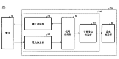
- FIG. 1 shows an example of the configuration of the equilibrium potential estimation apparatus 100.
- the equilibrium potential estimation apparatus 100 includes a voltage application unit 20, a current measurement unit 30, a signal processing unit 40, and an equilibrium potential estimation unit 50.
- the equilibrium potential estimation apparatus 100 is connected to the electrode 10 in contact with a sample (solution) containing a redox substance, and estimates the equilibrium potential of the solution.
- a solution when simply referred to as a solution, it refers to a solution for which an equilibrium potential is to be estimated.
- the electrode 10 performs an oxidation-reduction reaction with the oxidation-reduction substance contained in the solution, and exchanges electrons. Transfer of electrons is performed on the surface of the electrode 10.
- the redox substance include an oxidized mediator and a reduced mediator.
- the mediator that emits electrons becomes an oxidized mediator, and the mediator that enjoys electrons becomes a reduced mediator.
- the voltage application unit 20 applies a voltage to the electrode 10. For example, the application of a voltage to the electrode 10 is performed together with another electrode that applies a reference voltage called a reference electrode.
- the voltage application unit 20 may sweep the voltage applied to the electrode 10. Sweeping refers to changing the voltage applied to the electrode 10 with respect to time. Sweeping is not limited to linearly increasing and decreasing the voltage at a constant rate, but includes changing the voltage at an arbitrary rate of change. The sweep may also include a non-linear voltage change or a step-like voltage change in which discrete values continue.
- the current measuring unit 30 measures the current flowing through the electrode 10.
- the current measuring unit 30 transmits the measured current value to the signal processing unit 40.
- the signal processing unit 40 calculates a current integrated value of the current measured by the current measuring unit 30.
- the current integrated value is a total sum of currents that flow from when the voltage applying unit 20 applies a voltage to the electrode 10 until signal processing is performed. For example, if the total current in the direction flowing from the electrode 10 into the solution and the total current flowing in the solution from the electrode 10 are the same within the measurement period, the integrated current value becomes zero.
- the signal processing unit 40 determines a voltage condition that the voltage application unit 20 applies to the electrode 10 next.
- the reference range here may be arbitrarily changed according to the solution.
- the reference range may be a range from a predetermined value to a positive tolerance, a negative tolerance, or a positive / negative tolerance.
- the signal processing unit 40 determines whether or not the voltage applied by the voltage application unit 20 to the electrode 10 has converged when the integrated current value falls within the reference range. As a result of this determination, when it is determined that convergence has been achieved, the sweep is terminated. In addition to whether or not the voltage has converged, the signal processing unit 40 may determine whether or not the change amount of the current corresponding to the voltage sweep width is within an allowable range. .
- the determination of whether or not the amount of change in the current is within the allowable range is the absolute value of the current value observed corresponding to the voltage sweep width or the ⁇ value of the current value ( ⁇ is a real number greater than 0, and so on) ) Is within a certain range, whether the absolute value of the current value or the ⁇ value of the current value ( ⁇ is a real number smaller than 0, the same shall apply hereinafter) is outside the certain range, It is to determine whether or not the amount of change per sweep is within a certain range. That is, the determination referred to here is to determine whether or not the current is within the allowable range as a result. In the present specification, being within the reference range may include becoming the value of the reference when the width of the reference range is zero.
- the signal processing unit 40 may determine whether or not the amount of change in the integrated value of the current corresponding to the voltage sweep width is within an allowable range.
- the determination of whether or not the amount of change in the integrated value is within the allowable range is that the absolute value of the integrated value of the current observed corresponding to the voltage sweep width or the ⁇ value of the integrated value is within a certain range. Whether the absolute value of the integrated value or the ⁇ power of the integrated value is outside a certain range, and whether the amount of change per sweep of the integrated value is within a certain range. is there. That is, the determination referred to here is to determine whether or not the integrated value is within an allowable range as a result.
- the determination condition for this end is that the number of sweeps and the measurement time, such as whether the number of sweeps has reached a certain number or more, and whether the elapsed time from the measurement start time has reached a certain time or more.
- a condition based on the above may be used as the end determination condition. For example, when the number of sweeps is less than N (N is a natural number, the same shall apply hereinafter), the signal processing unit 40 determines to sweep the voltage in the direction opposite to the sweep direction in the previous sweep stage. When the number of times is N, it is determined to end the voltage sweep.
- the equilibrium potential estimation unit 50 estimates the equilibrium potential of the solution from the signal processing result of the signal processing unit 40.
- the equilibrium potential estimation unit 50 may output the estimated equilibrium potential as it is to the user. Further, the equilibrium potential estimation unit 50 may calculate the concentration of the oxidized mediator or the reduced mediator from the estimated equilibrium potential.
- FIG. 2 shows an example of the configuration of the blood sugar estimation device 300.
- the blood sugar estimation device 300 includes an electrode 10 and a concentration estimation device 200 connected to the electrode 10.
- the blood sugar estimation device 300 estimates a blood sugar level that is the concentration of glucose (glucose) in the blood.
- the blood glucose estimation device 300 is an example of a device that estimates the concentration of the redox substance from the reaction amount of the redox reaction with the electrode 10 caused by the redox substance. That is, the blood sugar estimation device 300 can similarly estimate the concentration of other solutions in addition to the blood sugar level by changing the enzyme or the like that reacts with the solution.
- An apparatus having the same configuration as that of the blood glucose estimation apparatus 300 can be used for measuring the amount of biological substances such as proteins, amino acids, and lipids, measuring the environment such as PH and harmful substances, and food inspection.
- the concentration estimation apparatus 200 includes an equilibrium potential estimation apparatus 100 and a concentration estimation unit 60.
- the concentration estimation unit 60 estimates the concentration of the solution based on the equilibrium potential estimated by the equilibrium potential estimation device 100.
- the concentration of the solution may be the concentration of the oxidized mediator or reduced mediator in the solution.
- the concentration of the solution can be calculated from the equilibrium potential using the Nernst equation.
- the Nernst equation is expressed as follows: Here, E is the equilibrium potential, E 0 is the standard electrode potential, R is the gas constant, T is the temperature (K), n is the number of mobile electrons, F is the Faraday constant, C ox is the concentration of the oxidized mediator, and C Red is Indicates the concentration of reduced mediator.
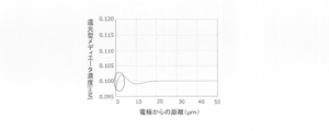
- FIG. 3 shows the concentration gradient of the reduced mediator in the solution.
- the concentration gradient is a concentration gradient with respect to the distance from the electrode 10.
- the vertical axis represents the reduced mediator concentration
- the horizontal axis represents the distance from the surface of the electrode 10.
- the concentration on the surface of the electrode 10 is referred to as surface concentration
- the concentration at a position away from the surface of the electrode 10 is referred to as bulk concentration.
- the position away from the surface of the electrode 10 is a position where the concentration of the solution is constant.
- the dotted line shows the reduced mediator concentration gradient of the ideal solution.
- the reduced mediator concentration gradient of the solution is constant regardless of the distance from the electrode 10 during measurement.
- the solid line indicates the actual concentration gradient when the electrode 10 is in contact with the solution.
- a redox reaction occurs due to the difference in electrochemical potential between the electrode 10 and the solution.
- the actual concentration gradient of the reduced mediator is different from the ideal concentration gradient of the reduced mediator.
- the equilibrium potential estimated by the equilibrium potential estimation apparatus 100 is based on the reaction at the interface between the electrode 10 and the solution, the equilibrium potential estimation apparatus 100 can actually estimate only the surface concentration of the solution. Therefore, in order to estimate the concentration of the solution more accurately, it is necessary to make the surface concentration of the solution the same as the bulk concentration of the solution.
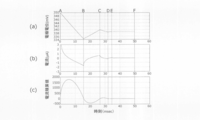
- FIG. 4 shows an example of a method for estimating the equilibrium potential.
- FIG. 4A shows the time change of the voltage applied to the electrode 10 by the voltage application unit 20.
- (B) of FIG. 4 shows the time change of the current measured by the current measuring unit 30.
- (C) of FIG. 4 shows the time change of the integrated current value calculated by the signal processing unit 40.
- the voltage application unit 20 sweeps the voltage from the initial voltage in a direction that decreases at a constant rate.
- Time A is a time during which the voltage application unit 20 applies an initial voltage to the electrode 10. If the equilibrium potential estimation method of this example is used, the equilibrium potential can be estimated for any value of the initial voltage. However, if the initial voltage is set in the vicinity of the equilibrium potential predicted from the characteristics of the solution, the estimation can be completed in a short time.
- the current measuring unit 30 detects a positive current and then detects a negative current.
- a positive current refers to a current flowing in the direction from the electrode 10 into the solution
- a negative current refers to a current flowing in a direction opposite to the positive current.
- the current measurement unit 30 measures a positive current
- an oxidation reaction occurs on the surface of the electrode 10
- the current measurement unit 30 measures a negative current a reduction reaction occurs on the surface of the electrode 10.
- the current integration value draws a mountain curve because the current is switched from positive to negative.
- Time B is the time when the integrated current value calculated by the signal processing unit 40 becomes zero.
- the time when the current integrated value becomes 0 is a turning point of the sweep speed of the applied voltage. In the present specification, the period from the return point of the sweep speed to the next return point is referred to as one cycle.
- the voltage application unit 20 applies a voltage having a reverse sweep direction to the electrode 10 in the period AB. That is, the applied voltage changes from a value smaller than the equilibrium potential of the solution to a larger value.
- the sweep speed in the period BC is controlled to half the sweep speed in the period AB.
- the current measured by the current measuring unit 30 changes from a negative value to a positive value.
- Point C is the time when the integrated current value calculated by the signal processing unit 40 becomes 0 again.
- the same cycle as the period AB and the period BC is repeated.
- the voltage applied by the voltage application unit 20 converges.
- the converged applied voltage is estimated as the equilibrium potential of the solution.
- the cycle of this example is repeated until the applied voltage converges and the equilibrium potential is estimated.
- the cycle may be repeated until a predetermined measurement time has elapsed.
- the solution used in the equilibrium potential estimation method of this example can be used again for estimation of the equilibrium potential.
- FIG. 5 shows the concentration gradient of the reduced mediator at time B in FIG.
- the vertical axis represents the reduced mediator concentration
- the horizontal axis represents the distance from the electrode 10.
- the concentration ratio according to the voltage applied to the electrode 10 is on the surface of the electrode 10. Since the voltage applied to the electrode 10 at time B is lower than the equilibrium potential of the bulk concentration, the surface concentration of the reduced mediator is higher than the bulk concentration.
- FIG. 6 shows the concentration gradient of the reduced mediator at time C in FIG.
- the difference between the voltage applied by the voltage application unit 20 to the electrode 10 and the equilibrium potential is smaller than that at time B.
- the concentration gradient of the reduced mediator is smaller in the vicinity of electrode 10 than at time B.
- FIG. 7 shows the concentration gradient of the reduced mediator at time D in FIG.
- the difference between the voltage applied by the voltage application unit 20 to the electrode 10 and the equilibrium potential is smaller than that at time C.
- the concentration gradient of the reduced mediator is smaller in the vicinity of the electrode 10 than at time C.
- FIG. 8 shows the concentration gradient of the reduced mediator at time E in FIG.
- the difference between the voltage applied by the voltage application unit 20 to the electrode 10 and the equilibrium potential is smaller than that at time D.
- the concentration gradient of the reduced mediator is smaller in the vicinity of the electrode 10 than at time D.
- FIG. 9 shows the concentration gradient of the reduced mediator at time F in FIG. At time F, the surface concentration of the reduced mediator is equal to the bulk concentration of the reduced mediator. That is, a constant reduced mediator concentration is obtained regardless of the distance from the electrode 10.
- the equilibrium potential estimation apparatus 100 eliminates the concentration gradient of the solution by controlling the voltage applied to the electrode 10. Thereby, the equilibrium potential estimation apparatus 100 can accurately estimate the equilibrium potential of the solution.
- FIG. 10 shows an example of a flowchart according to the equilibrium potential estimation method.
- the equilibrium potential estimation apparatus 100 estimates the equilibrium potential by executing steps S100 to S110.
- step S100 the signal processing unit 40 sets an initial voltage, an initial sweep speed, and an initial sweep direction. If the equilibrium potential estimation method according to the present embodiment is used, the equilibrium potential can be estimated by arbitrarily setting the initial voltage, the initial sweep speed, and the initial sweep direction. However, the time required for estimating the equilibrium potential can be shortened by setting appropriate values for the initial voltage, initial sweep speed, and initial sweep direction.
- step S101 the voltage application unit 20 applies a voltage to the electrode 10.
- step S ⁇ b> 102 the current measurement unit 30 measures the current flowing through the electrode 10.
- step S103 the signal processing unit 40 calculates an integrated current value.
- step S ⁇ b> 104 the signal processing unit 40 determines whether or not the voltage application unit 20 is sweeping in the direction of decreasing the applied voltage. When sweeping in the direction of decreasing the applied voltage, the process proceeds to step S105, and when sweeping in the direction of increasing the applied voltage, the process proceeds to step S106.
- step S105 the signal processing unit 40 determines whether or not the integrated current value is negative. If the current integrated value is negative, the process proceeds to step S107. If the current integrated value is positive, the process proceeds to step S109. On the other hand, in step S106, the signal processing unit 40 determines whether or not the current integrated value is positive. If the current integrated value is positive, the process proceeds to step S107. If the current integrated value is negative, the process proceeds to step S109.
- step S107 the signal processing unit 40 determines whether or not the variation of the applied voltage has converged. Whether or not the fluctuation of the applied voltage has converged is determined based on whether or not a predetermined voltage sweep width is within an allowable range. When it is determined that the applied voltage has converged, the process proceeds to step S110, and when it is determined that the applied voltage has not converged, the process proceeds to step S108.
- step S108 the signal processing unit 40 reverses the voltage sweep direction. Further, the signal processing unit 40 may decrease the sweep speed in step S108. As the cycle is repeated, it converges to the equilibrium potential, so the time for one cycle is shortened. Therefore, the time difference of one cycle can be reduced by reducing the sweep speed. For example, the signal processing unit 40 decreases the sweep speed at a predetermined decrease rate of the sweep speed every time step S108 is executed. In this case, the sweep speed decreases with the power of the decrease rate. Further, the signal processing unit 40 may control the sweep speed so that the time of each cycle is constant. In this way, the signal processing unit 40 changes the voltage sweep speed by estimating the equilibrium potential once, so that it becomes easier to converge to the equilibrium potential than when the sweep speed is constant. When step S108 is executed, the process proceeds to step S109.
- step S109 the voltage to be applied next is determined at the current sweep speed and sweep direction.
- the current sweep speed and sweep direction refer to the sweep speed and sweep direction set in step S108 when step S108 is executed.
- the signal processing unit 40 next determines the voltage to be applied to the electrode 10, and proceeds to step S101.
- step S110 the equilibrium potential estimation unit 50 estimates the voltage applied by the voltage application unit 20 as the equilibrium potential.
- the equilibrium potential estimation apparatus 100 may output the estimated equilibrium potential to the outside.
- the equilibrium potential estimation apparatus 100 repeats steps S101 to S109 until the applied voltage converges in step S107.
- the equilibrium potential estimation method of this example determines whether or not to reverse the sweep direction in step S108 based on the sweep direction of the applied voltage determined in step S104 and the sign of the current integrated value in steps S105 and S106. . Thereby, even when the applied voltage is swept away from the equilibrium potential, the sweep direction can be controlled to approach the equilibrium potential.
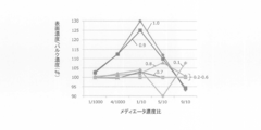
- FIG. 11 shows the dependence of the solution concentration gradient on the decrease rate of the sweep rate.
- the vertical axis represents the ratio (%) of the surface concentration to the bulk concentration of the solution, and the horizontal axis represents the mediator concentration ratio.
- Each curve shows a simulation result when the decreasing rate of the sweep rate is changed from 0.1 to 1.0.
- the sweep speed at the start of measurement is 1.0 V / sec.
- the mediator concentration ratio is a ratio of the reduced mediator to the sum of the oxidized mediator and the reduced mediator.
- the mediator concentration ratio is measured in a state where it is in an equilibrium state.
- the ratio of the surface concentration to the bulk concentration is 100 (%), it indicates that the surface concentration of the solution is equal to the bulk concentration.
- the ratio of the surface concentration to the bulk concentration is close to 100 (%) at any mediator concentration ratio.
- the rate of decrease of the sweep rate is determined based on the measurement time, mediator concentration gradient, voltage sweep cycle time, and the like. For example, the decrease rate of the sweep speed is set to a value that allows the estimation to be completed within an allowable measurement time. Further, the decrease rate of the sweep rate may be determined so that the distance from the surface of the electrode 10 that affects the solution becomes equal in one cycle of the voltage sweep. Influencing the solution means that the concentration of the solution changes due to the reaction between the electrode 10 and the solution. The distance from the electrode 10 surface that affects the solution is determined by the length of time of one cycle, the diffusion coefficient of the solution, and the like. That is, basically, the longer one cycle is, the farther it can be from the electrode 10.
- FIG. 12 shows the relationship between the decreasing rate of the sweep rate and the equilibrium potential error (mV).
- the decreasing rate of the sweep speed is changed from 0.1 to 1.0.
- the mediator concentration ratios are 1/1000, 4/1000, 1/10, 5/10 and 9/10, respectively.
- the equilibrium potential error indicates a difference from the equilibrium potential estimated from the theoretical equilibrium potential using the decrease rate of each sweep speed.
- the equilibrium potential error converges to within 0.1 mV.
- the decreasing rate of the sweep speed is 0.8 to 1.0
- the equilibrium potential error is 0.1 mV or more, and the equilibrium potential converges at a position where the concentration gradient is not eliminated.
- the decreasing rate of the sweep speed is 0.1 to 0.7
- it can be determined that the equilibrium potential error is sufficiently small.
- the sweep rate reduction rate is 0.2 to 0.7
- the equilibrium potential error is around 0 mV.
- the sweep rate of the sweep speed is 0.1 and 0.2, the sweep may be too slow to converge within the measurement time.
- the sweep rate reduction rate is preferably 0.4 or more.
- 13 to 17 show the simulation results of the concentration gradient of the reducing substance.
- the simulation of this example is a result of changing the mediator concentration ratio in five ways. Each simulation result shows the relationship between the mediator concentration ratio and the concentration gradient after the voltage has converged.
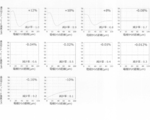
- FIG. 13 shows the relationship between the decrease rate of the sweep rate and the concentration gradient of the reduced mediator.
- the mediator concentration ratio in this example is 1/1000.
- the reduction rate of the sweep rate and the difference in the surface concentration of the reduced mediator with respect to the bulk concentration of the reduced mediator are shown.
- the magnitude of the error of the surface concentration with respect to the bulk concentration of the reduced mediator is + 3%, + 2.5%, + 0.6%, and ⁇ 0.15, respectively.
- FIG. 14 shows the relationship between the decrease rate of the sweep rate and the concentration gradient of the reduced mediator.
- the mediator concentration ratio in this example is 4/1000.
- the magnitude of the error of the surface concentration with respect to the bulk concentration of the reduced mediator is + 12.5%, + 12.5%, + 1.25%, and ⁇ 0, respectively. 375%, -0.075%, -0.03%, -0.025%, -0.025%, -0.025%, + 2%.
- FIG. 15 shows the relationship between the decrease rate of the sweep rate and the concentration gradient of the reduced mediator.
- the mediator concentration ratio in this example is 1/10.
- the magnitude of the surface concentration error with respect to the bulk concentration of the reduced mediator is + 30%, + 25%, + 2%, + 3%, and -0.075%, respectively. , ⁇ 0.02%, ⁇ 0.012%, ⁇ 0.013%, + 0.03%, and + 4%.
- FIG. 16 shows the relationship between the decrease rate of the sweep rate and the concentration gradient of the reduced mediator.
- the mediator concentration ratio in this example is 5/10.
- the magnitude of the error of the surface concentration with respect to the bulk concentration of the reduced mediator is + 12%, + 10%, + 8%, ⁇ 0.08%, ⁇ 0, respectively.
- FIG. 17 shows the relationship between the decrease rate of the sweep rate and the concentration gradient of the reduced mediator.
- the mediator concentration ratio in this example is 9/10.
- the magnitude of the error of the surface concentration with respect to the bulk concentration of the reduced mediator is ⁇ 6.667%, ⁇ 5.556%, + 0.667%, + 0.189%, -0.0667%, -0.01333%, -0.01333%, -0.0222%, + 0.1667%, + 7.7778%.
- the range of the potential drop rate may be 0.1 to 0.8 times. More desirably, the range of the potential drop rate is 0.2 to 0.7 times. More preferably, the range of the potential drop rate is 0.4 to 0.6.
- the actually used potential drop rate may be set in consideration of the estimation time and the estimation accuracy.
- the equilibrium potential can be estimated in principle.
- the voltage converges, and the mediator concentration and the equilibrium potential may be correlated.
- the mediator concentration can be estimated by drawing a calibration curve even if the estimated equilibrium potential and the true equilibrium potential are deviated.
- FIG. 18 is a diagram for explaining a conventional constant voltage current measurement method.
- the graph shows the time change of the current value.
- 18A to 18D show the concentration of the solution with respect to the distance from the electrode 10 at each time of the electrode 10 and time a to time d.
- (A) in FIG. 18 is a schematic diagram of the solution concentration gradient at time a, which is the start of measurement. At time a, the concentration of the solution becomes uniform regardless of the distance from the electrode 10. That is, the surface concentration of the solution is equal to the bulk concentration.
- FIG. 18B is a schematic diagram of the solution concentration gradient at time b. At time b, the concentration gradually decreases from the vicinity of the electrode 10. That is, the surface concentration of the solution is lowered.
- (C) in FIG. 18 is a schematic diagram of a solution concentration gradient at time c.
- the concentration further decreases from the vicinity of the electrode 10.
- the concentration of the solution is reduced to a distance farther from the electrode 10 compared to time b. The distance at which the concentration of the solution decreases is determined depending on the diffusion coefficient of the solution.
- (D) of FIG. 18 is a schematic diagram of the solution concentration gradient at time d.
- the diffusion of the measurement substance is rate-limiting.
- the concentration of the solution is reduced to a further distance from the electrode 10 than at time c.
- the concentration is estimated from the change in the current flowing through the electrode 10.
- the change in current is the slope of the current.
- the theoretical formula of the constant voltage current measurement is as follows.
- n and F are constants
- A is an electrode area
- C is a solution concentration
- D is a diffusion coefficient
- t is time.
- the equilibrium potential estimation method has various advantages compared to the constant voltage current measurement method.
- the equilibrium potential estimation method is not affected by the electrode area compared to the constant voltage current measurement method.
- the current is proportional to the electrode area A
- high machining accuracy of the electrode is required.
- the processing accuracy of the electrode is increased using an expensive material such as gold.
- the equilibrium potential estimation method is controlled so that the integrated current value becomes zero, there is no influence by the electrode area A. That is, since the processing accuracy of the electrode 10 is not required, a material such as carbon having a rough surface can be used. Since the material cost of carbon is lower than that of materials such as gold, the manufacturing cost can be reduced.
- the equilibrium potential estimation method is not affected by the diffusion coefficient compared to the constant voltage current measurement method.
- the current changes according to the diffusion coefficient of the solution.
- the equilibrium potential estimation method is controlled so that the integrated current value becomes zero, there is no influence of the diffusion coefficient. That is, when the equilibrium potential estimation method is used, the blood glucose level can be accurately estimated regardless of the difference in diffusion coefficient caused by the individual difference of blood.
- the equilibrium potential estimation method is less affected by interfering substances than the constant voltage current measurement method.
- the interference substance is a substance that undergoes an oxidation-reduction reaction on the surface of the electrode 10 by applying a voltage to the electrode 10.
- many interfering substances are oxidized on the surface of the electrode 10, and in addition to the current due to the oxidation of the reduced mediator, the current due to the oxidizing of the interfering substance flows, and the measured current value increases, so the concentration of the solution is accurate Cannot be estimated.
- the equilibrium potential estimation method the applied voltage is lower than in the constant voltage current measurement method, and the current due to the interference substance being oxidized is small. Therefore, the equilibrium potential estimation method is less affected by the interfering substance than the constant voltage current measurement method, and can be estimated with higher accuracy.
- the equilibrium potential estimation method is a non-destructive measurement that repeats both oxidation and reduction reactions, the same solution can be repeatedly measured. That is, since the solution measured by the equilibrium potential estimation method can be measured again after a lapse of a certain time, the time change of the solution can be detected.
- the balanced potential estimation method has an advantage that the signal noise (S / N) ratio is improved and the measurement object can be made wider.
- FIG. 19 shows an example of a hardware configuration of a computer 1900 according to the present embodiment.
- a computer 1900 according to this embodiment is connected to a CPU peripheral unit having a CPU 2000, a RAM 2020, a graphic controller 2075, and a display device 2080 that are connected to each other by a host controller 2082, and to the host controller 2082 by an input / output controller 2084.
- Input / output unit having communication interface 2030, hard disk drive 2040, and CD-ROM drive 2060, and legacy input / output unit having ROM 2010, flexible disk drive 2050, and input / output chip 2070 connected to input / output controller 2084 With.
- the host controller 2082 connects the RAM 2020 to the CPU 2000 and the graphic controller 2075 that access the RAM 2020 at a high transfer rate.
- the CPU 2000 operates based on programs stored in the ROM 2010 and the RAM 2020 and controls each unit.
- the graphic controller 2075 acquires image data generated by the CPU 2000 or the like on a frame buffer provided in the RAM 2020 and displays it on the display device 2080.
- the graphic controller 2075 may include a frame buffer for storing image data generated by the CPU 2000 or the like.
- the input / output controller 2084 connects the host controller 2082 to the communication interface 2030, the hard disk drive 2040, and the CD-ROM drive 2060, which are relatively high-speed input / output devices.
- the communication interface 2030 communicates with other devices via a network.
- the hard disk drive 2040 stores programs and data used by the CPU 2000 in the computer 1900.
- the CD-ROM drive 2060 reads a program or data from the CD-ROM 2095 and provides it to the hard disk drive 2040 via the RAM 2020.
- the ROM 2010, the flexible disk drive 2050, and the relatively low-speed input / output device of the input / output chip 2070 are connected to the input / output controller 2084.
- the ROM 2010 stores a boot program that the computer 1900 executes at startup and / or a program that depends on the hardware of the computer 1900.
- the flexible disk drive 2050 reads a program or data from the flexible disk 2090 and provides it to the hard disk drive 2040 via the RAM 2020.
- the input / output chip 2070 connects the flexible disk drive 2050 to the input / output controller 2084 and inputs / outputs various input / output devices via, for example, a parallel port, a serial port, a keyboard port, a mouse port, and the like. Connect to controller 2084.
- the program provided to the hard disk drive 2040 via the RAM 2020 is stored in a recording medium such as the flexible disk 2090, the CD-ROM 2095, or an IC card and provided by the user.
- the program is read from the recording medium, installed in the hard disk drive 2040 in the computer 1900 via the RAM 2020, and executed by the CPU 2000.
- the program installed in the computer 1900 and causing the computer 1900 to function as the signal processing unit 40 includes a signal processing module. These programs or modules work on the CPU 2000 or the like to cause the computer 1900 to function as a signal processing unit.
- the information processing described in these programs functions as the signal processing unit 40, which is a specific means in which the software and the various hardware resources described above cooperate when read by the computer 1900.
- the specific signal processing part 40 according to the intended purpose is constructed
- a program installed in the computer 1900 and causing the computer 1900 to function as the concentration estimation apparatus 200 includes a voltage application module, a current measurement module, a signal processing module, an equilibrium potential estimation module, and a concentration estimation module. These programs or modules work on the CPU 2000 or the like to cause the computer 1900 to function as a concentration estimation device.
- the information processing described in these programs is read by the computer 1900, whereby the voltage application unit 20, the current measurement unit 30, the signal, which are specific means in which the software and the various hardware resources described above cooperate with each other. It functions as the processing unit 40, the equilibrium potential estimation unit 50, and the concentration estimation unit 60. And the specific density
- the CPU 2000 executes a communication program loaded on the RAM 2020 and executes a communication interface based on the processing content described in the communication program.
- a communication process is instructed to 2030.
- the communication interface 2030 reads transmission data stored in a transmission buffer area or the like provided on a storage device such as the RAM 2020, the hard disk drive 2040, the flexible disk 2090, or the CD-ROM 2095, and sends it to the network.
- the reception data transmitted or received from the network is written into a reception buffer area or the like provided on the storage device.
- the communication interface 2030 may transfer transmission / reception data to / from the storage device by a DMA (direct memory access) method. Instead, the CPU 2000 transfers the storage device or the communication interface 2030 as a transfer source.
- the transmission / reception data may be transferred by reading the data from the data and writing the data to the communication interface 2030 or the storage device of the transfer destination.
- the CPU 2000 is all or necessary from among files or databases stored in an external storage device such as a hard disk drive 2040, a CD-ROM drive 2060 (CD-ROM 2095), and a flexible disk drive 2050 (flexible disk 2090).
- This portion is read into the RAM 2020 by DMA transfer or the like, and various processes are performed on the data on the RAM 2020. Then, CPU 2000 writes the processed data back to the external storage device by DMA transfer or the like.
- the RAM 2020 and the external storage device are collectively referred to as a memory, a storage unit, or a storage device.
- the CPU 2000 can also store a part of the RAM 2020 in the cache memory and perform reading and writing on the cache memory. Even in such a form, the cache memory bears a part of the function of the RAM 2020. Therefore, in the present embodiment, the cache memory is also included in the RAM 2020, the memory, and / or the storage device unless otherwise indicated. To do.
- the CPU 2000 performs various operations, such as various operations, information processing, condition determination, information search / replacement, etc., described in the present embodiment, specified for the data read from the RAM 2020 by the instruction sequence of the program. Is written back to the RAM 2020. For example, when performing the condition determination, the CPU 2000 determines whether the various variables shown in the present embodiment satisfy the conditions such as large, small, above, below, equal, etc., compared to other variables or constants. When the condition is satisfied (or not satisfied), the program branches to a different instruction sequence or calls a subroutine.
- the CPU 2000 can search for information stored in a file or database in the storage device. For example, in the case where a plurality of entries in which the attribute value of the second attribute is associated with the attribute value of the first attribute are stored in the storage device, the CPU 2000 displays the plurality of entries stored in the storage device. The entry that matches the condition in which the attribute value of the first attribute is specified is retrieved, and the attribute value of the second attribute that is stored in the entry is read, thereby associating with the first attribute that satisfies the predetermined condition The attribute value of the specified second attribute can be obtained.
- the program or module shown above may be stored in an external recording medium.
- an optical recording medium such as DVD or CD
- a magneto-optical recording medium such as MO
- a tape medium such as an IC card, and the like
- a storage device such as a hard disk or RAM provided in a server system connected to a dedicated communication network or the Internet may be used as a recording medium, and the program may be provided to the computer 1900 via the network.
- Embodiment 1 Applying a voltage to the electrode and sweeping said voltage; A second step of measuring the current flowing through the electrode; A third stage for determining whether or not the sweep width of the voltage is within an allowable range when the integrated value of the current reaches a predetermined value; A fourth step of estimating a voltage value within the allowable range as an equilibrium potential of the redox material when determined to be within the allowable range; And a fifth stage of sweeping the voltage in a direction opposite to the sweep direction in the previous sweep stage when determined to be outside the allowable range.
- Emodiment 4 The method for estimating an equilibrium potential of a redox substance according to any one of embodiments 1 to 3, wherein in the fifth stage, the voltage is swept slower than the sweep speed in the previous sweep stage.
- Emodiment 5 The method for estimating an equilibrium potential of a redox substance according to embodiment 4, wherein the sweep speed in the fifth stage is 0.1 to 0.8 times the sweep speed in the previous sweep stage.
- Emodiment 6 The method for estimating an equilibrium potential of a redox substance according to embodiment 5, wherein the sweep speed in the fifth stage is 0.2 to 0.7 times the sweep speed in the previous sweep stage.
- a voltage application unit for applying a voltage to the electrodes; A current measuring unit for measuring a current flowing through the electrode; A signal for instructing the voltage application unit to sweep the voltage, and for determining whether or not the sweep width of the voltage is within an allowable range when the integrated value of the current reaches a predetermined value.
- a processing unit and The signal processing unit When within the allowable range, the voltage value within the allowable range is estimated as an equilibrium potential of the redox material, and when not within the allowable range, the voltage is swept in the direction opposite to the previous sweep direction. Equilibrium potential estimation device for redox substances that instructs voltage application unit.
- the signal processing unit The equilibrium of the redox material according to claim 10, wherein the voltage application unit is repeatedly instructed to sweep the voltage in a direction opposite to the previous sweep direction until the voltage sweep width falls within the allowable range.
- Potential estimation device The signal processing unit From when the integrated value of the current becomes a predetermined value until the integrated value of the current becomes a predetermined value next, the time during which the voltage is swept is constant.
- the signal processing unit The redox according to any one of embodiments 10 to 12, wherein when the voltage sweep width is not within the allowable range, the voltage application unit is instructed to sweep the voltage slower than a previous sweep speed.
- a device for estimating the equilibrium potential of a substance [Embodiment 14] The signal processing unit 14. The voltage application unit is instructed to sweep the voltage at a speed that is 0.1 to 0.8 times the previous sweep speed when the sweep width of the voltage is not within the allowable range. Equilibrium potential estimation device for redox substances.
- the signal processing unit The voltage application unit is instructed to sweep the voltage at a speed 0.2 to 0.7 times the previous sweep speed when the sweep width of the voltage is not within the allowable range.
- Equilibrium potential estimation device for redox substances The signal processing unit 16.
- the voltage application unit is instructed to sweep the voltage at a speed 0.4 to 0.6 times the previous sweep speed when the voltage sweep width is not within the allowable range.
- Equilibrium potential estimation device for redox substances The signal processing unit The apparatus for estimating an equilibrium potential of an oxidation-reduction substance according to any one of embodiments 10 to 16, wherein when the sign of the integrated value is inverted, it is determined whether a sweep width of the voltage is within an allowable range.
- An oxidation-reduction substance concentration estimation device comprising: an estimation unit that estimates the concentration of the oxidation-reduction substance based on the voltage value.
- [Embodiment 19] A program that causes a computer to function as the signal processing unit in the oxidation-reduction substance equilibrium potential estimation device according to any one of Embodiments 10 to 17.
- [Embodiment 22] A concentration-reducing apparatus for redox substances according to embodiment 18, A blood glucose
Landscapes
- Health & Medical Sciences (AREA)
- Life Sciences & Earth Sciences (AREA)
- Chemical & Material Sciences (AREA)
- Physics & Mathematics (AREA)
- Molecular Biology (AREA)
- Chemical Kinetics & Catalysis (AREA)
- Electrochemistry (AREA)
- Analytical Chemistry (AREA)
- Biochemistry (AREA)
- General Health & Medical Sciences (AREA)
- General Physics & Mathematics (AREA)
- Immunology (AREA)
- Pathology (AREA)
- Hematology (AREA)
- Biophysics (AREA)
- Investigating Or Analyzing Materials By The Use Of Electric Means (AREA)
Abstract
L'invention concerne un procédé d'estimation de potentiel d'équilibre pour une substance redox qui comprend les étapes suivantes : l'application d'une tension à une électrode en contact avec un échantillon comprenant la substance redox et l'analyse de la tension, la mesure du courant circulant à travers l'électrode, le fait de déterminer s'il faut balayer la tension dans une direction opposée à la direction de balayage de l'étape de balayage précédente ou arrêter le balayage de tension lorsqu'une valeur de courant accumulée tombe dans une plage standard, l'estimation de la valeur de la tension comme étant le potentiel d'équilibre de la substance redox lorsqu'il est déterminé d'arrêter le balayage de la tension, et le balayage de la tension dans la direction opposée à la direction de balayage de l'étape de balayage précédente lorsqu'il est décidé de balayer la tension.
Priority Applications (4)
| Application Number | Priority Date | Filing Date | Title |
|---|---|---|---|
| CN201580061752.1A CN107110820B (zh) | 2014-11-12 | 2015-11-06 | 平衡电位估计方法、平衡电位估计装置、浓度估计装置、程序、介质以及血糖估计装置 |
| EP15859251.9A EP3206024B1 (fr) | 2014-11-12 | 2015-11-06 | Procédé d'estimation de potentiel d'équilibre, dispositif d'estimation de potentiel d'équilibre, dispositif d'estimation de concentration, et dispositif d'estimation de sucre dans le sang |
| JP2016559024A JP6371408B2 (ja) | 2014-11-12 | 2015-11-06 | 平衡電位推定方法、平衡電位推定装置、濃度推定装置、プログラム、媒体及び血糖推定装置 |
| US15/593,343 US10641730B2 (en) | 2014-11-12 | 2017-05-12 | Equilibrium potential estimating method, equilibrium potential estimating device, concentration estimating device, program, medium and blood sugar estimating device |
Applications Claiming Priority (2)
| Application Number | Priority Date | Filing Date | Title |
|---|---|---|---|
| JP2014229614 | 2014-11-12 | ||
| JP2014-229614 | 2014-11-12 |
Related Child Applications (1)
| Application Number | Title | Priority Date | Filing Date |
|---|---|---|---|
| US15/593,343 Continuation US10641730B2 (en) | 2014-11-12 | 2017-05-12 | Equilibrium potential estimating method, equilibrium potential estimating device, concentration estimating device, program, medium and blood sugar estimating device |
Publications (1)
| Publication Number | Publication Date |
|---|---|
| WO2016076232A1 true WO2016076232A1 (fr) | 2016-05-19 |
Family
ID=55954319
Family Applications (1)
| Application Number | Title | Priority Date | Filing Date |
|---|---|---|---|
| PCT/JP2015/081363 Ceased WO2016076232A1 (fr) | 2014-11-12 | 2015-11-06 | Procédé d'estimation de potentiel d'équilibre, dispositif d'estimation de potentiel d'équilibre, dispositif d'estimation de concentration, programme, support et dispositif d'estimation de sucre dans le sang |
Country Status (5)
| Country | Link |
|---|---|
| US (1) | US10641730B2 (fr) |
| EP (1) | EP3206024B1 (fr) |
| JP (1) | JP6371408B2 (fr) |
| CN (1) | CN107110820B (fr) |
| WO (1) | WO2016076232A1 (fr) |
Citations (3)
| Publication number | Priority date | Publication date | Assignee | Title |
|---|---|---|---|---|
| JPS5852556A (ja) * | 1981-09-24 | 1983-03-28 | Terumo Corp | イオン選択透過膜およびイオンセンサ− |
| JPH0240551A (ja) * | 1988-08-01 | 1990-02-09 | Jonan Kagaku Sangyo Kk | 電極電解洗浄法 |
| JPH06148138A (ja) * | 1992-11-02 | 1994-05-27 | Mitsui Eng & Shipbuild Co Ltd | 電量分析法 |
Family Cites Families (6)
| Publication number | Priority date | Publication date | Assignee | Title |
|---|---|---|---|---|
| US20100000881A1 (en) * | 2003-10-30 | 2010-01-07 | North Carolina State University | Electrochemical detection of nucleic acid hybridization |
| CN1635371A (zh) * | 2003-12-26 | 2005-07-06 | 财团法人工业技术研究院 | 利用脉冲伏安法侦测微量物质的方法 |
| KR101427559B1 (ko) | 2004-05-14 | 2014-08-07 | 바이엘 헬스케어 엘엘씨 | 생물학적 분석물의 검사를 위한 전압전류식 시스템 |
| KR20130100022A (ko) | 2005-09-30 | 2013-09-06 | 바이엘 헬스케어 엘엘씨 | 게이트형 전압 전류 측정 분석물 결정 방법 |
| EA201390485A1 (ru) * | 2011-02-28 | 2013-09-30 | Луоксис Дайэгностикс, Инк. | Способ и устройство для измерения окислительно-восстановительного потенциала |
| US9689837B2 (en) * | 2012-08-10 | 2017-06-27 | National University Corporation Toyohashi University Of Technology | Device for measuring oxidation-reduction potential and method for measuring oxidation-reduction potential |
-
2015
- 2015-11-06 WO PCT/JP2015/081363 patent/WO2016076232A1/fr not_active Ceased
- 2015-11-06 CN CN201580061752.1A patent/CN107110820B/zh not_active Expired - Fee Related
- 2015-11-06 EP EP15859251.9A patent/EP3206024B1/fr active Active
- 2015-11-06 JP JP2016559024A patent/JP6371408B2/ja not_active Expired - Fee Related
-
2017
- 2017-05-12 US US15/593,343 patent/US10641730B2/en not_active Expired - Fee Related
Patent Citations (3)
| Publication number | Priority date | Publication date | Assignee | Title |
|---|---|---|---|---|
| JPS5852556A (ja) * | 1981-09-24 | 1983-03-28 | Terumo Corp | イオン選択透過膜およびイオンセンサ− |
| JPH0240551A (ja) * | 1988-08-01 | 1990-02-09 | Jonan Kagaku Sangyo Kk | 電極電解洗浄法 |
| JPH06148138A (ja) * | 1992-11-02 | 1994-05-27 | Mitsui Eng & Shipbuild Co Ltd | 電量分析法 |
Non-Patent Citations (2)
| Title |
|---|
| AKIRA FUJISHIMA ET AL.: "Denki Kagaku Sokuteiho (Jo)", GIHODO SHUPPAN CO. LTD, 15 November 1984 (1984-11-15), pages 145 - 148, XP008185659 * |
| BOBACKA J ET AL.: "Equilibrium potential of potentiometric ion sensors under steady-state current by using current-reversal chronopotentiometry.", J ELECTROANAL CHEM, vol. 509, no. 1, 10 August 2001 (2001-08-10), pages 27 - 30, XP055376915 * |
Also Published As
| Publication number | Publication date |
|---|---|
| CN107110820A (zh) | 2017-08-29 |
| JPWO2016076232A1 (ja) | 2017-08-17 |
| EP3206024B1 (fr) | 2020-01-08 |
| US10641730B2 (en) | 2020-05-05 |
| US20170248545A1 (en) | 2017-08-31 |
| EP3206024A1 (fr) | 2017-08-16 |
| CN107110820B (zh) | 2019-05-07 |
| JP6371408B2 (ja) | 2018-08-08 |
| EP3206024A4 (fr) | 2017-11-01 |
Similar Documents
| Publication | Publication Date | Title |
|---|---|---|
| JP4381413B2 (ja) | バイオセンサー・システム | |
| Westgard et al. | Assessing quality on the Sigma scale from proficiency testing and external quality assessment surveys | |
| CN106093134B (zh) | 金属氧化物传感器阵列响应漂移的补偿方法 | |
| JP2017151118A (ja) | 既使用で乾燥したセンサを検出するシステム及び方法 | |
| JP2014527186A5 (fr) | ||
| CN109690304A (zh) | 通过使用来自两个电极的交替输出信号进行电化学分析的方法 | |
| Nowotny et al. | Precision and accuracy of blood glucose measurements using three different instruments | |
| CN102954991B (zh) | 生物感测器及生物感测方法 | |
| AU2017219171A1 (en) | Extrapolation of interpolated sensor data to increase sample throughput | |
| Brunkhorst et al. | Blood glucose measurements in the critically ill: more than just a blood draw | |
| JP6371408B2 (ja) | 平衡電位推定方法、平衡電位推定装置、濃度推定装置、プログラム、媒体及び血糖推定装置 | |
| Reviansyah et al. | Noninvasive detection of alpha-amylase in saliva using screen-printed carbon electrodes: A promising biomarker for clinical oral diagnostics | |
| US8620590B2 (en) | Dose surface method for determination of analyte ratios | |
| JP2017531785A (ja) | 拡散を測定するための方法 | |
| Hardeman et al. | Test 1 analyser for determination of ESR. 1. Practical evaluation and comparison with the Westergren technique | |
| Stojek | Pulse voltammetry | |
| JP2019132705A (ja) | 電気化学測定方法、電気化学測定装置、プログラムおよびコンピュータ可読記録媒体 | |
| Rollborn et al. | Analysis of HbA1c on an automated multicapillary zone electrophoresis system | |
| CN120102856A (zh) | 样本浓度检测方法、标准曲线组的建立及优化方法 | |
| JP2009164538A (ja) | 閾値電圧演算方法、閾値電圧演算プログラムおよび閾値電圧演算装置 | |
| CN119943397B (zh) | 一种用于血糖仪的温度检测与补偿方法及相关设备 | |
| Sjöberg et al. | Dual mode antimony electrode for simultaneous measurements of PO2 and pH | |
| US20250362267A1 (en) | Calibration apparatus, calibration method, and non-transitory computer-readable recording medium | |
| CN112582026B (zh) | 基于效率的qPCR初始浓度检测的高鲁棒性六参数全局拟合法 | |
| CN107810409A (zh) | 校正针对钙抑制的crea传感器的方法 |
Legal Events
| Date | Code | Title | Description |
|---|---|---|---|
| 121 | Ep: the epo has been informed by wipo that ep was designated in this application |
Ref document number: 15859251 Country of ref document: EP Kind code of ref document: A1 |
|
| ENP | Entry into the national phase |
Ref document number: 2016559024 Country of ref document: JP Kind code of ref document: A |
|
| NENP | Non-entry into the national phase |
Ref country code: DE |
|
| REEP | Request for entry into the european phase |
Ref document number: 2015859251 Country of ref document: EP |