WO2016104438A1 - 摩擦ブレーキ構造 - Google Patents
摩擦ブレーキ構造 Download PDFInfo
- Publication number
- WO2016104438A1 WO2016104438A1 PCT/JP2015/085699 JP2015085699W WO2016104438A1 WO 2016104438 A1 WO2016104438 A1 WO 2016104438A1 JP 2015085699 W JP2015085699 W JP 2015085699W WO 2016104438 A1 WO2016104438 A1 WO 2016104438A1
- Authority
- WO
- WIPO (PCT)
- Prior art keywords
- brake
- brake shoe
- plate
- friction
- output side
- Prior art date
- Legal status (The legal status is an assumption and is not a legal conclusion. Google has not performed a legal analysis and makes no representation as to the accuracy of the status listed.)
- Ceased
Links
Images


Classifications
-
- F—MECHANICAL ENGINEERING; LIGHTING; HEATING; WEAPONS; BLASTING
- F16—ENGINEERING ELEMENTS AND UNITS; GENERAL MEASURES FOR PRODUCING AND MAINTAINING EFFECTIVE FUNCTIONING OF MACHINES OR INSTALLATIONS; THERMAL INSULATION IN GENERAL
- F16D—COUPLINGS FOR TRANSMITTING ROTATION; CLUTCHES; BRAKES
- F16D65/00—Parts or details
- F16D65/14—Actuating mechanisms for brakes; Means for initiating operation at a predetermined position
- F16D65/16—Actuating mechanisms for brakes; Means for initiating operation at a predetermined position arranged in or on the brake
- F16D65/18—Actuating mechanisms for brakes; Means for initiating operation at a predetermined position arranged in or on the brake adapted for drawing members together, e.g. for disc brakes
- F16D65/186—Actuating mechanisms for brakes; Means for initiating operation at a predetermined position arranged in or on the brake adapted for drawing members together, e.g. for disc brakes with full-face force-applying member, e.g. annular
-
- H—ELECTRICITY
- H02—GENERATION; CONVERSION OR DISTRIBUTION OF ELECTRIC POWER
- H02K—DYNAMO-ELECTRIC MACHINES
- H02K7/00—Arrangements for handling mechanical energy structurally associated with dynamo-electric machines, e.g. structural association with mechanical driving motors or auxiliary dynamo-electric machines
- H02K7/10—Structural association with clutches, brakes, gears, pulleys or mechanical starters
- H02K7/102—Structural association with clutches, brakes, gears, pulleys or mechanical starters with friction brakes
-
- F—MECHANICAL ENGINEERING; LIGHTING; HEATING; WEAPONS; BLASTING
- F16—ENGINEERING ELEMENTS AND UNITS; GENERAL MEASURES FOR PRODUCING AND MAINTAINING EFFECTIVE FUNCTIONING OF MACHINES OR INSTALLATIONS; THERMAL INSULATION IN GENERAL
- F16D—COUPLINGS FOR TRANSMITTING ROTATION; CLUTCHES; BRAKES
- F16D65/00—Parts or details
- F16D65/02—Braking members; Mounting thereof
- F16D65/04—Bands, shoes or pads; Pivots or supporting members therefor
- F16D65/092—Bands, shoes or pads; Pivots or supporting members therefor for axially-engaging brakes, e.g. disc brakes
- F16D65/095—Pivots or supporting members therefor
- F16D65/097—Resilient means interposed between pads and supporting members or other brake parts
- F16D65/0971—Resilient means interposed between pads and supporting members or other brake parts transmitting brake actuation force, e.g. elements interposed between brake piston and pad
-
- F—MECHANICAL ENGINEERING; LIGHTING; HEATING; WEAPONS; BLASTING
- F16—ENGINEERING ELEMENTS AND UNITS; GENERAL MEASURES FOR PRODUCING AND MAINTAINING EFFECTIVE FUNCTIONING OF MACHINES OR INSTALLATIONS; THERMAL INSULATION IN GENERAL
- F16D—COUPLINGS FOR TRANSMITTING ROTATION; CLUTCHES; BRAKES
- F16D55/00—Brakes with substantially-radial braking surfaces pressed together in axial direction, e.g. disc brakes
- F16D55/02—Brakes with substantially-radial braking surfaces pressed together in axial direction, e.g. disc brakes with axially-movable discs or pads pressed against axially-located rotating members
-
- F—MECHANICAL ENGINEERING; LIGHTING; HEATING; WEAPONS; BLASTING
- F16—ENGINEERING ELEMENTS AND UNITS; GENERAL MEASURES FOR PRODUCING AND MAINTAINING EFFECTIVE FUNCTIONING OF MACHINES OR INSTALLATIONS; THERMAL INSULATION IN GENERAL
- F16D—COUPLINGS FOR TRANSMITTING ROTATION; CLUTCHES; BRAKES
- F16D2121/00—Type of actuator operation force
- F16D2121/14—Mechanical
Definitions
- the present invention relates to a friction brake structure for a rotating electric machine such as a motor.
- Fig. 6 shows the structure of a conventional motor friction brake.
- a stator 101 and a rotor 102 are provided in a motor case 100 of the motor.
- the rotor 102 is supported on the rotation shaft 103.
- the rotating shaft 103 is supported by the output side bearing 106a and the non-output side bearing 106b.
- a brake plate 104 is fixed to the rotating shaft 103.
- a plurality of brake shoes 105 are arranged to face the brake plate 104.
- the brake shoe 105 is inserted into a hole 108 formed in the axial direction of the bearing housing portion 107 in which the counter-output side bearing 106b is mounted.
- the brake shoe 105 is slidably contacted with the brake plate 104 by being biased toward the brake plate 104 by the coil spring 109.
- the coil spring 109 is supported by the spring pressing plate 110.
- the brake shoe 105 is in sliding contact with the brake plate 104, so that a braking action and a holding torque when stopped are obtained.
- an abnormal sound called a squealing of the brake may occur due to the rotation of the brake shoe as the brake plate rotates.
- the present invention aims to reduce the occurrence of abnormal noise in the friction brake structure.
- a brake plate fixed to a rotating shaft of a rotating electrical machine, an annular brake shoe disposed opposite to the brake plate, and a shaft
- a brake shoe support plate that engages with a fixed portion of the rotating electrical machine so as to be movable in a direction, supports the brake shoe, and receives a biasing action so that the brake shoe slides on the brake plate.
- a convex portion is provided on one of the surface of the brake shoe opposite to the sliding contact surface with the brake plate and the support surface of the brake shoe support plate, and an engaging portion that engages with the convex portion is provided on the other side. be able to.
- the brake plate can be fixed to the rotating shaft at a position outside the non-output side bearing that supports the rotating shaft.
- the outer diameter of the brake plate can be made smaller than the outer diameter of the counter-output side bearing, and the brake plate can be supported by the inner ring portion of the counter-output side bearing.
- the outer diameter of the brake shoe can be made smaller than the outer diameter of the non-output side bearing.
- the friction brake structure may further include a conical coil spring as a mechanism for imparting the biasing action to the brake shoe support plate.
- the friction brake structure further includes a stopper for restricting the movement of the brake shoe support plate toward the brake plate in the axial direction when the axial thickness of the brake shoe becomes a predetermined value or less. It may be.
- a friction brake structure includes a brake plate fixed to a rotating shaft of a rotating electrical machine, an annular brake shoe disposed opposite to the brake plate, and an axial movement.
- a brake shoe support plate that engages with a fixed portion of the rotating electric machine as much as possible, supports the brake shoe, and receives a biasing action to slide the brake shoe against the brake plate.
- the annular brake shoe is brought into sliding contact with the brake plate, and the brake shoe is prevented from rotating together with the brake plate, so that the rotational moment due to the frictional force of the brake shoe is suppressed, and the connection between the brake shoe and the brake plate is suppressed. It is possible not to change the spring constant of the formed part. As a result, it is possible to suppress the self-excited vibration of the brake shoe and reduce the occurrence of abnormal noise called brake squeal.
- FIG. 3 is a partially enlarged view of FIG. 2. It is a disassembled perspective view of a friction brake structure. It is sectional drawing which shows the friction brake structure of the conventional motor.
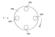
- FIG. 1 shows a state in which the brake plate 104 and the plurality of brake shoes 105 in the motor shown in FIG. 6 are viewed from the non-output side of the motor.
- four brake shoes 105 provided at equal intervals in the circumferential direction are shown, and reference numerals 105 1 to 105 4 are assigned to distinguish them from each other.
- the rotation direction of the brake plate 104 is indicated by an arrow A1.
- Abnormal noise in the friction brake structure is a phenomenon classified as a coupled self-excited vibration.
- a coupled system comprising a portion and the brake shoe 105 2 and the coil spring 109 of the brake plate 104 is shown in FIG. 2 a picture obtained by viewing from the direction of arrow Y in FIG.
- Equation (1) is an equation of motion for the brake plate position
- Equation (2) is an equation of motion for the brake shoe position
- Equation (3) is an equation of motion for brake shoe rotation.
- the integrand f (l) is a function representing a pressure between the brake plate 104 and the brake shoe 105 2.
- l are coordinates in sliding surface 105a on the basis of the intersection Q of the axis and the sliding surface 105a of the brake shoe 105 2.
- f (l) can be approximately expressed as follows.
- the matrix in the above characteristic equation is a symmetric matrix, it will not be a self-excited vibration system, but it will be a self-excited vibration system if the elements in which the row number and column number are exchanged have different signs. It has been.
- the components related to the rotation of the brake shoe are not symmetrical and may have different signs. That is, self-excited vibration in the rotational direction of the brake shoe occurs, which can cause abnormal noise.
- Patent Document 1 describes that each brake shoe is fixed to an annular support.
- the brake shoe may slightly rotate with the annular support as the brake plate rotates, and self-excited vibration may occur. As a result, abnormal sounds can occur.
- the motor 1 has a motor case 10 as a casing.
- a stator 11 and a rotor 12 are provided in the motor case 10.
- the rotor 12 is supported by a rotating shaft 15 supported by the output side bearing 13 and the non-output side bearing 14.
- the non-output side bearing 14 is attached to a bearing housing portion 10 a provided integrally with the motor case 10.
- An axial hole 10b is formed in the bearing housing portion 10a so as to communicate with the outside of the motor case 10.
- Hole 10b is oblong, the outer peripheral portion is formed of two planar portions 10b 1 and 10b 2 so as to face each other.
- the hole 10b has a so-called D-cut shape.
- An annular brake plate 20 is fixed to the rotary shaft 15 at a position outside the non-output side bearing 14.
- the rotating shaft 15 passes through the hole 20a of the brake plate 20.
- the brake plate 20 is also supported by the inner ring portion 14 a of the non-output side bearing 14.
- the outer diameter of the brake plate 20 is smaller than the outer diameter of the non-output side bearing 14. The brake plate 20 rotates with the rotary shaft 15.
- An annular brake shoe 30 is provided so as to face the brake plate 20.
- the rotating shaft 15 passes through the hole 30a of the brake shoe 30.
- the outer diameter of the brake shoe 30 is smaller than the outer diameter of the non-output side bearing 14.
- four convex portions 30c are provided at equal intervals in the circumferential direction on the axial end surface 30b opposite to the axial end surface that is in sliding contact with the brake plate 20.
- the material of the brake shoe 30 can be PPS (polyphenylene sulfide) resin, PTFE (polytetrafluoroethylene) resin, or the like.
- the brake shoe 30 is supported by an annular brake shoe support plate 40 that is movable in the axial direction.
- the rotary shaft 15 passes through a first hole 40a provided in the center of the brake shoe support plate 40.
- the outer peripheral portion 40b of the brake shoe support plate 40, across the first hole 40a so as to face each other two planar portions 40b 1 and 40b 2 are formed.
- the two flat portions 40b 1 and 40b 2 are provided to engage with the two flat portions 10b 1 and 10b 2 , respectively.
- the brake shoe support plate 40 has a substantially oval so-called D-cut shape.
- the brake shoe support plate 40 is provided with four second holes 40c that are respectively engaged with the four protrusions 30c at equal intervals in the circumferential direction.
- the brake shoe 30 is fixed to the brake shoe support plate 40 by engaging each of the four second holes 40c with each of the four convex portions 30c.
- a conical coil spring 50 is disposed on the outer axial end surface of the brake shoe support plate 40, that is, on the surface opposite to the support surface of the brake shoe 30.
- the conical coil spring 50 is supported by a conical coil spring support plate 60 attached to the motor case 10 by screws 61.
- the brake shoe support plate 40 receives the urging action of the conical coil spring 50 to bring the brake shoe 30 into sliding contact with the brake plate 20.
- the stopper 10c is provided so as to do this.
- the stopper 10 c has a brake shoe support plate 40 toward the axial brake plate 20. It is provided to regulate the movement of
- the brake shoe 30 is fixed to the brake shoe support plate 40, and the brake shoe support plate 40 can move in the axial direction and cannot rotate about the axis. Therefore, when the motor 1 is driven, the rotation of the rotation shaft 15 can be braked without the brake shoe 30 rotating with the rotation of the rotation shaft 15 and the brake plate 20. When the drive of the motor 1 is stopped, the rotation of the rotary shaft 15 can be quickly stopped by the braking force by the brake shoe 30. At the time of this stop, a fixed holding force is obtained with respect to the rotating shaft 15. In this way, a braking action during driving and a holding torque during stopping are obtained.
- An annular brake shoe 30 capable of ensuring a sliding contact area is brought into sliding contact with the brake plate 20 to prevent the brake shoe 30 from rotating together with the brake plate 20. Therefore, the rotational moment due to the frictional force of the brake shoe 30 can be suppressed, and the spring constant of the coupled portion of the brake shoe 30 and the brake plate 20 can be prevented from changing.
- the first term on the right side represents a restoring force that generates a simple vibration, and this coefficient is a spring constant generally referred to. Since the tilt angle ⁇ is included in the term after the second term, according to the related art shown in FIG. 6, the same effect as that in which the spring constant is changed is generated.
- the self-excited vibration of the brake shoe 30 is suppressed, and abnormal noise called squealing of the brake is generated. Can be reduced.
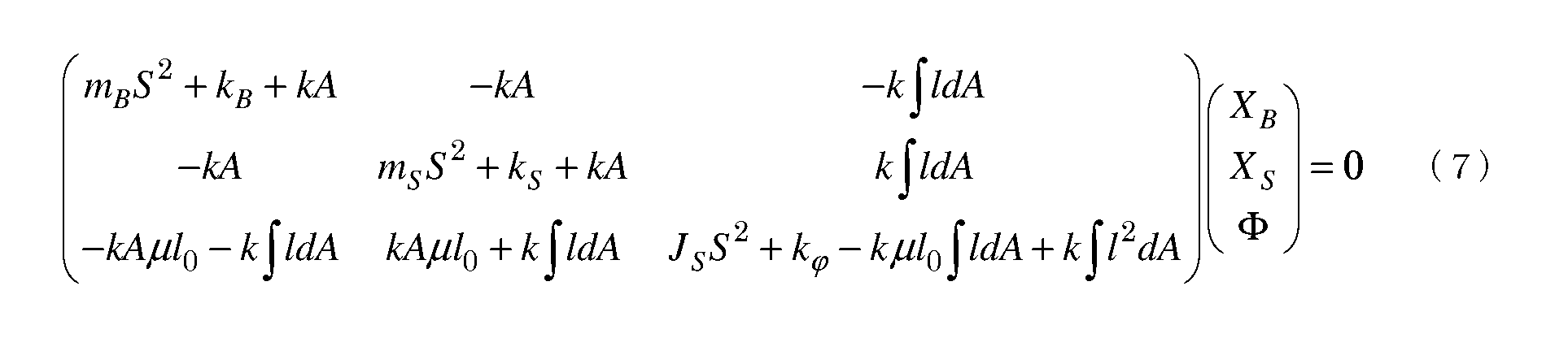
- equation (7) The effect of reducing the occurrence of abnormal noise will be described in relation to equation (7). Since it is difficult to handle the three-variable expression (7) as it is, determination of stability is considered with two variables with reduced elements. Suppose the equation can be expressed as: In this equation, it is known that when the product of non-diagonal elements is negative, a self-excited vibration system is obtained.
- the brake shoe 30 is annular, it is possible to secure a sliding contact area, so that the brake shoe 30 can be prevented from rotating together with the brake plate 20. That is, unlike the prior art shown in FIG. 6, the tilt angle ⁇ is zero or infinitely close to zero.
- equation (7) considering the part excluding the equation of motion for brake shoe rotation, In equation (9), the product of the two off-diagonal elements is positive and does not form a self-excited vibration system. Therefore, according to the above embodiment, it is possible to reduce the occurrence of abnormal brake sound.
- the tilt angle ⁇ is generated, so it is included in the non-diagonal element Can take both positive and negative values. Therefore, the product of two off-diagonal elements may be negative. That is, according to the prior art, self-excited vibration is generated, and there is a possibility that abnormal noise of the brake is generated.
- the brake shoe 30 gradually wears due to friction with the brake plate 20, and the axial thickness of the brake shoe 30 decreases. With this decrease, the brake shoe support plate 40 receiving the urging force of the conical coil spring 50 moves to the brake plate 20 side. The brake shoe support plate 40 eventually hits the stopper 10c, and further movement toward the brake plate 20 is restricted by the stopper 10c. As the wear of the brake shoe 30 further progresses, the brake shoe 30 does not come into sliding contact with the brake plate 20. Therefore, it is possible to suppress the occurrence of sparks due to sliding contact in a state where wear has progressed to some extent.
- the above-described restriction is not necessary, and the conical coil spring has a free height that allows a sufficient biasing force to be obtained until the brake shoe support plate 40 hits the stopper part 10c. 50 can be selected. Therefore, a stable braking force can be obtained until the brake shoe support plate 40 contacts the stopper 10c.
- the brake plate 104 is provided on the inner side in the axial direction when viewed from the non-output side bearing 106b.
- the brake shoe 105 is disposed on the radially outer side of the counter-output side bearing 106b so as not to interfere with the counter-output side bearing 106b. Accordingly, the outer diameter of the brake plate 104 becomes relatively large. That is, the brake shoe 105 comes into sliding contact with the brake plate 104 at a position relatively away from the axis of the rotating shaft 103. Inevitably, the peripheral speed of the sliding contact portion is relatively high.
- the amount of wear of the brake shoe is proportional to the value of the product PV of the contact pressure P [MPa] generated by the spring biasing force F and the peripheral speed V [m / s] on the sliding contact surface of the brake shoe.
- the peripheral speed V is greater than a certain value, the wear amount is large regardless of P. As a result, it is difficult to extend the braking force life in FIG.
- the outer diameter of the brake plate 20 and the outer diameter of the brake shoe 30 are both smaller than the outer diameter of the non-output-side bearing 14. Therefore, the slidable contact portion is relatively close to the axial center of the rotating shaft 15, and an increase in the peripheral speed V at the slidable contact portion can be suppressed.
- the brake shoe 30 is annular and the sliding contact area is secured. , P can also be suppressed. As a result, the value of the product PV can be reduced and the life of the braking force can be extended.
- conical coil spring 50 instead of the conical coil spring 50, an arbitrary urging mechanism such as a normal coil spring or an elastic mechanism may be provided.
- the second hole portion 40c may be an engaging portion that engages with the convex portion 30c, and any of a shape that protrudes from the support surface of the brake shoe support plate 40 to the opposite surface and a shape that is recessed without protruding. Good. Furthermore, the convex portion 30 c may be provided in the brake shoe support plate 40, and the second hole portion 40 c may be provided in the brake shoe 30.
- the brake shoe support plate 40 is not limited to the bearing housing portion 10a that is a fixed portion in the motor 1 that does not move even when the motor 1 is driven, and may be engaged with another fixed portion.
- the friction brake structure can be provided in a rotating electric machine other than the motor 1.
Landscapes
- Engineering & Computer Science (AREA)
- General Engineering & Computer Science (AREA)
- Mechanical Engineering (AREA)
- Power Engineering (AREA)
- Braking Arrangements (AREA)
- Connection Of Motors, Electrical Generators, Mechanical Devices, And The Like (AREA)
Abstract
Description
このように、環状のブレーキシューをブレーキ板に摺接させ、かつブレーキシューがブレーキ板とともに回転しないようにしたことにより、ブレーキシューの摩擦力による回転モーメントを抑制し、ブレーキシューとブレーキ板の連成部のばね定数を変化させないようにすることができる。その結果、ブレーキシューの自励振動を抑制し、ブレーキの鳴きと呼ばれる異常音の発生を低減することができる。
発明者はまず、異常音の発生原理に関して検討を行った。以下に詳細を説明する。
摩擦ブレーキ構造における異常音は、連成系の自励振動に分類される現象である。ブレーキ板104の一部分とブレーキシュー1052とコイルスプリング109とを含む連成系を、図1の矢印Yの方向から見た様子を図2に示している。同図におけるブレーキ板104の弾性をkBとし、ブレーキ板104の質量をmBとし、ブレーキ板104の位置をxBとする。また、ブレーキシュー1052の弾性をkとし、ブレーキシュー1052の質量をmSとし、ブレーキシュー1052の位置をxSとする。さらに、コイルスプリング109の弾性をkSとする。同図におけるφは、ブレーキ板104が回転し、ブレーキ板104の一部分が矢印A2の方向に移動したことによるブレーキシュー1052の倒れ角を示している。加えて、ブレーキシュー1052の慣性モーメントをJSとし、ブレーキ板104とブレーキシュー1052の摩擦係数をμとし、ブレーキシュー1052の重心Gから摺接面105aまでの距離をl0とし、時間をtとする。また、ブレーキ板104とブレーキシュー1052の接触面積をAとし、ブレーキシュー1052の重心G周りの回転に関するばね定数をkφとする。平衡点近傍でのこれらの量の間には次の関係が成り立つ。


これまでに述べた異常音の発生原理を踏まえて、本発明の一実施形態を以下に説明する。
上述したように、ブレーキシュー30はブレーキシュー支持板40に固定されており、該ブレーキシュー支持板40は軸方向に移動可能かつ軸周りに回転不可能とされている。そのため、モータ1の駆動時は、回転軸15及びブレーキ板20の回転に伴ってブレーキシュー30が回転してしまうことなく、回転軸15の回転を制動することができる。モータ1の駆動を停止させると、ブレーキシュー30による制動力により、迅速に回転軸15の回転を止めることができる。この停止時においては回転軸15に関し一定の保持力が得られる。このように、駆動時における制動作用及び停止時における保持トルクが得られる。
ここで、連成振動を表す式(4)~(6)の各々において、右辺第1項は単振動を発生させる復元力を表現しており、この係数が一般に言われるばね定数である。第2項より後の項に倒れ角φが含まれていることにより、図6に示した従来技術によれば、ばね定数が変化したことと同じ効果が発生する。
上記実施形態によれば、ブレーキシュー30とブレーキ板20の連成部のばね定数を変化させないようにすることで、ブレーキシュー30の自励振動を抑制し、ブレーキの鳴きと呼ばれる異常音の発生を低減することができる。




円錐コイルばね50に代えて、通常のコイルばねなどの任意の付勢機構あるいは弾撥機構を設けてもよい。
10 モータケース
10a ベアリングハウジング部
10b 穴部
10b1 平面部
10b2 平面部
10c 当て止め部
11 固定子
12 回転子
13 出力側軸受
14 反出力側軸受
14a 内輪部
15 回転軸
20 ブレーキ板
20a 穴部
30 ブレーキシュー
30a 穴部
30b 軸方向端面
30c 凸部
40 ブレーキシュー支持板
40a 第1穴部
40b 外周部
40b1 平面部
40b2 平面部
40c 第2穴部
40d 外周縁部
50 円錐コイルばね
60 円錐コイルばね支持板
61 ねじ
100 モータケース
101 固定子
102 回転子
103 回転軸
104 ブレーキ板
105 ブレーキシュー
1051~1054 ブレーキシュー
105a 摺接面
106a 出力側軸受
106b 反出力側軸受
107 ベアリングハウジング部
108 穴
109 コイルスプリング
110 スプリング押え板
G 重心
φ 倒れ角
l0 長さ
l 座標
Q 交点
A1、A2、Y 矢印
Claims (7)
- 回転電機の回転軸に固定されたブレーキ板と、
該ブレーキ板に対向して配置されている環状のブレーキシューと、
軸方向に移動可能なように前記回転電機の固定部に係合し、前記ブレーキシューを支持するとともに付勢作用を受けて前記ブレーキシューを前記ブレーキ板に摺接させるブレーキシュー支持板と
を備えたことを特徴とする摩擦ブレーキ構造。 - 前記ブレーキシューにおける前記ブレーキ板との摺接面と反対側の面と、前記ブレーキシュー支持板の支持面との一方に凸部を設け、他方に前記凸部に係合する係合部を設けている、請求項1に記載の摩擦ブレーキ構造。
- 前記ブレーキ板が、前記回転軸を支持する反出力側軸受よりも外側の位置において前記回転軸に固定されている、請求項1に記載の摩擦ブレーキ構造。
- 前記ブレーキ板の外径が、前記反出力側軸受の外径より小さく、
前記ブレーキ板が前記反出力側軸受の内輪部に支持されている、請求項3に記載の摩擦ブレーキ構造。 - 前記ブレーキシューの外径が、前記反出力側軸受の外径より小さい、請求項3に記載の摩擦ブレーキ構造。
- 前記付勢作用を前記ブレーキシュー支持板に付与する機構として円錐コイルばねを更に備えた請求項1に記載の摩擦ブレーキ構造。
- 前記ブレーキシューの軸方向の厚さが一定値以下になった場合に、前記ブレーキシュー支持板の、軸方向前記ブレーキ板側への移動を規制する当て止め部を更に備えた請求項1に記載の摩擦ブレーキ構造。
Priority Applications (4)
| Application Number | Priority Date | Filing Date | Title |
|---|---|---|---|
| EP15873006.9A EP3239552B1 (en) | 2014-12-26 | 2015-12-21 | Friction brake structure |
| CN201580069685.8A CN107110257B (zh) | 2014-12-26 | 2015-12-21 | 摩擦制动器结构 |
| KR1020177016344A KR102437405B1 (ko) | 2014-12-26 | 2015-12-21 | 마찰 브레이크 구조 |
| US15/539,842 US10598235B2 (en) | 2014-12-26 | 2015-12-21 | Friction brake structure |
Applications Claiming Priority (2)
| Application Number | Priority Date | Filing Date | Title |
|---|---|---|---|
| JP2014265847A JP6339933B2 (ja) | 2014-12-26 | 2014-12-26 | 摩擦ブレーキ構造 |
| JP2014-265847 | 2014-12-26 |
Publications (1)
| Publication Number | Publication Date |
|---|---|
| WO2016104438A1 true WO2016104438A1 (ja) | 2016-06-30 |
Family
ID=56150457
Family Applications (1)
| Application Number | Title | Priority Date | Filing Date |
|---|---|---|---|
| PCT/JP2015/085699 Ceased WO2016104438A1 (ja) | 2014-12-26 | 2015-12-21 | 摩擦ブレーキ構造 |
Country Status (7)
| Country | Link |
|---|---|
| US (1) | US10598235B2 (ja) |
| EP (1) | EP3239552B1 (ja) |
| JP (1) | JP6339933B2 (ja) |
| KR (1) | KR102437405B1 (ja) |
| CN (1) | CN107110257B (ja) |
| TW (1) | TWI671477B (ja) |
| WO (1) | WO2016104438A1 (ja) |
Families Citing this family (2)
| Publication number | Priority date | Publication date | Assignee | Title |
|---|---|---|---|---|
| US11411464B2 (en) * | 2015-07-28 | 2022-08-09 | Dewertokin Technology Group Co., Ltd. | Braking device for an electric drive motor |
| KR102487166B1 (ko) * | 2016-11-23 | 2023-01-10 | 현대자동차 주식회사 | 모터의 레졸버 장착 구조 |
Citations (3)
| Publication number | Priority date | Publication date | Assignee | Title |
|---|---|---|---|---|
| JPS55135237A (en) * | 1979-04-06 | 1980-10-21 | Toyota Motor Corp | Disk brake |
| JPS56109934A (en) * | 1980-02-04 | 1981-08-31 | Toyota Motor Corp | Disc brake |
| JPS59186535U (ja) * | 1983-05-31 | 1984-12-11 | 三菱電機株式会社 | ブレ−キ開放機構 |
Family Cites Families (20)
| Publication number | Priority date | Publication date | Assignee | Title |
|---|---|---|---|---|
| DE1243926B (de) | 1962-09-15 | 1967-07-06 | Ferodo Sa | Bremsklotz fuer Teilbelagscheibenbremsen |
| FR2135689A5 (ja) * | 1971-03-09 | 1972-12-22 | Potain Sa | |
| US3667578A (en) * | 1971-05-14 | 1972-06-06 | Harold Beck & Sons Inc | Bi-directional drive released brake |
| DE2625990C2 (de) | 1976-06-10 | 1984-09-06 | Karl-Ernst 4924 Barntrup Brinkmann | Elektromagnetisch lüftbare Federdruckbremse |
| US4289216A (en) * | 1979-04-06 | 1981-09-15 | Toyota Jidosha Kogyo Kabushiki | Disc brake |
| JPS587935A (ja) | 1981-07-07 | 1983-01-17 | Kokusai Denshin Denwa Co Ltd <Kdd> | トランスバーサル形スミアデスミアフイルタ |
| JPS587935U (ja) * | 1981-07-09 | 1983-01-19 | 特殊精工株式会社 | スプリング制動電磁ブレ−キ |
| JPS5882417U (ja) * | 1981-11-29 | 1983-06-03 | 日野自動車株式会社 | ブロ−バイガス制御装置 |
| JPS59186535A (ja) | 1983-04-07 | 1984-10-23 | 東芝テック株式会社 | 電気掃除機 |
| EP0209943B1 (de) * | 1985-07-26 | 1992-11-11 | Mavilor Systèmes S.A. | Elektromotor mit Scheibenbremse |
| CA2112609A1 (en) * | 1993-12-30 | 1995-07-01 | Eddy Desrochers | Combination brake and clutch assembly for electric motors |
| JPH0940339A (ja) * | 1995-08-02 | 1997-02-10 | Mitsubishi Denki Bill Techno Service Kk | エスカレータ停止時ブレーキ滑り防止装置 |
| SE505313C2 (sv) * | 1996-05-31 | 1997-08-04 | Fhp Elmotor Ab | Bromssystem |
| JPH1189173A (ja) | 1997-09-02 | 1999-03-30 | Oriental Motor Co Ltd | モータの摩擦ブレーキ構造 |
| US5967272A (en) | 1998-02-27 | 1999-10-19 | Eaton Corporation | Clutch brake wear limiter |
| JP2002051528A (ja) | 2000-07-31 | 2002-02-15 | Minebea Co Ltd | ステッピングモータ |
| FR2834391B1 (fr) * | 2001-12-28 | 2004-04-02 | Somfy | Dispositif de frein a disques et de transmission de couple |
| US8820489B2 (en) * | 2007-03-07 | 2014-09-02 | Arvinmeritor Technology, Llc | Electric motor with static brake |
| JP2012122574A (ja) * | 2010-12-10 | 2012-06-28 | Hitachi Industrial Equipment Systems Co Ltd | 電磁ブレーキ及び電動機 |
| FR3023656B1 (fr) * | 2014-07-08 | 2016-08-05 | Sagem Defense Securite | Actionneur electromecanique a dispositif de freinage double fonction |
-
2014
- 2014-12-26 JP JP2014265847A patent/JP6339933B2/ja active Active
-
2015
- 2015-12-21 KR KR1020177016344A patent/KR102437405B1/ko active Active
- 2015-12-21 CN CN201580069685.8A patent/CN107110257B/zh active Active
- 2015-12-21 US US15/539,842 patent/US10598235B2/en active Active
- 2015-12-21 WO PCT/JP2015/085699 patent/WO2016104438A1/ja not_active Ceased
- 2015-12-21 EP EP15873006.9A patent/EP3239552B1/en active Active
- 2015-12-24 TW TW104143568A patent/TWI671477B/zh active
Patent Citations (3)
| Publication number | Priority date | Publication date | Assignee | Title |
|---|---|---|---|---|
| JPS55135237A (en) * | 1979-04-06 | 1980-10-21 | Toyota Motor Corp | Disk brake |
| JPS56109934A (en) * | 1980-02-04 | 1981-08-31 | Toyota Motor Corp | Disc brake |
| JPS59186535U (ja) * | 1983-05-31 | 1984-12-11 | 三菱電機株式会社 | ブレ−キ開放機構 |
Non-Patent Citations (1)
| Title |
|---|
| See also references of EP3239552A4 * |
Also Published As
| Publication number | Publication date |
|---|---|
| KR20170099887A (ko) | 2017-09-01 |
| US10598235B2 (en) | 2020-03-24 |
| CN107110257B (zh) | 2019-05-17 |
| JP2016125572A (ja) | 2016-07-11 |
| KR102437405B1 (ko) | 2022-08-29 |
| JP6339933B2 (ja) | 2018-06-06 |
| TW201631265A (zh) | 2016-09-01 |
| CN107110257A (zh) | 2017-08-29 |
| TWI671477B (zh) | 2019-09-11 |
| EP3239552A1 (en) | 2017-11-01 |
| EP3239552B1 (en) | 2019-11-06 |
| US20170370429A1 (en) | 2017-12-28 |
| EP3239552A4 (en) | 2018-11-21 |
Similar Documents
| Publication | Publication Date | Title |
|---|---|---|
| JPWO2017098663A1 (ja) | フラット型波動歯車装置 | |
| JP2009186013A (ja) | 転がり軸受け用の支持部材 | |
| JP6409754B2 (ja) | ファン | |
| JP2017022957A (ja) | 振動波モータ | |
| JP6339933B2 (ja) | 摩擦ブレーキ構造 | |
| CN110062859A (zh) | 密封装置 | |
| CN109307058B (zh) | 齿轮单元、减速装置以及清洁机器人 | |
| EP3139056B1 (en) | Fluid driving device, motor assembly and centrifugal friction clutch | |
| KR101993407B1 (ko) | 브레이크 일체형 구동 모듈 및 이의 동작 방법 | |
| JP6295773B2 (ja) | 真空ポンプ | |
| WO2020059695A1 (ja) | 軸受装置 | |
| US9920798B2 (en) | Braking device | |
| CN110418906A (zh) | 碟形弹簧 | |
| JP2012013219A (ja) | リングフォイル軸受 | |
| JP2008092748A (ja) | 超音波モータ | |
| JP5671637B2 (ja) | メカニカルシール | |
| KR101221686B1 (ko) | 공작기계용 베어링 예압 조절장치 | |
| JP6182709B2 (ja) | 軸力起因型トルク伝達装置 | |
| CN215950198U (zh) | 离心式制动器及具有回转体的器具 | |
| JP2007024255A (ja) | 遠心式クラッチ装置 | |
| JP6618731B2 (ja) | 制動装置 | |
| JP2021021468A (ja) | ギヤ装置およびギヤドモータ | |
| US20130316864A1 (en) | Transmission apparatus and transmission shaft control mechanism | |
| JPWO2018158905A1 (ja) | 回転操作部品 | |
| JP2016133209A (ja) | 歯車装置 |
Legal Events
| Date | Code | Title | Description |
|---|---|---|---|
| 121 | Ep: the epo has been informed by wipo that ep was designated in this application |
Ref document number: 15873006 Country of ref document: EP Kind code of ref document: A1 |
|
| ENP | Entry into the national phase |
Ref document number: 20177016344 Country of ref document: KR Kind code of ref document: A |
|
| NENP | Non-entry into the national phase |
Ref country code: DE |
|
| REEP | Request for entry into the european phase |
Ref document number: 2015873006 Country of ref document: EP |
|
| WWE | Wipo information: entry into national phase |
Ref document number: 15539842 Country of ref document: US |