WO2016129595A1 - Câble d'acier de renforcement d'article en caoutchouc et pneumatique l'utilisant - Google Patents
Câble d'acier de renforcement d'article en caoutchouc et pneumatique l'utilisant Download PDFInfo
- Publication number
- WO2016129595A1 WO2016129595A1 PCT/JP2016/053827 JP2016053827W WO2016129595A1 WO 2016129595 A1 WO2016129595 A1 WO 2016129595A1 JP 2016053827 W JP2016053827 W JP 2016053827W WO 2016129595 A1 WO2016129595 A1 WO 2016129595A1
- Authority
- WO
- WIPO (PCT)
- Prior art keywords
- steel cord
- core
- sheath
- filament
- filaments
- Prior art date
- Legal status (The legal status is an assumption and is not a legal conclusion. Google has not performed a legal analysis and makes no representation as to the accuracy of the status listed.)
- Ceased
Links
Images


Classifications
-
- D—TEXTILES; PAPER
- D07—ROPES; CABLES OTHER THAN ELECTRIC
- D07B—ROPES OR CABLES IN GENERAL
- D07B1/00—Constructional features of ropes or cables
- D07B1/06—Ropes or cables built-up from metal wires, e.g. of section wires around a hemp core
- D07B1/0606—Reinforcing cords for rubber or plastic articles
- D07B1/062—Reinforcing cords for rubber or plastic articles the reinforcing cords being characterised by the strand configuration
-
- B—PERFORMING OPERATIONS; TRANSPORTING
- B60—VEHICLES IN GENERAL
- B60C—VEHICLE TYRES; TYRE INFLATION; TYRE CHANGING; CONNECTING VALVES TO INFLATABLE ELASTIC BODIES IN GENERAL; DEVICES OR ARRANGEMENTS RELATED TO TYRES
- B60C9/00—Reinforcements or ply arrangement of pneumatic tyres
-
- D—TEXTILES; PAPER
- D07—ROPES; CABLES OTHER THAN ELECTRIC
- D07B—ROPES OR CABLES IN GENERAL
- D07B1/00—Constructional features of ropes or cables
- D07B1/06—Ropes or cables built-up from metal wires, e.g. of section wires around a hemp core
-
- D—TEXTILES; PAPER
- D07—ROPES; CABLES OTHER THAN ELECTRIC
- D07B—ROPES OR CABLES IN GENERAL
- D07B2201/00—Ropes or cables
- D07B2201/20—Rope or cable components
- D07B2201/2001—Wires or filaments
- D07B2201/2009—Wires or filaments characterised by the materials used
-
- D—TEXTILES; PAPER
- D07—ROPES; CABLES OTHER THAN ELECTRIC
- D07B—ROPES OR CABLES IN GENERAL
- D07B2201/00—Ropes or cables
- D07B2201/20—Rope or cable components
- D07B2201/2015—Strands
- D07B2201/2024—Strands twisted
- D07B2201/2029—Open winding
-
- D—TEXTILES; PAPER
- D07—ROPES; CABLES OTHER THAN ELECTRIC
- D07B—ROPES OR CABLES IN GENERAL
- D07B2201/00—Ropes or cables
- D07B2201/20—Rope or cable components
- D07B2201/2047—Cores
- D07B2201/2052—Cores characterised by their structure
- D07B2201/2059—Cores characterised by their structure comprising wires
- D07B2201/2061—Cores characterised by their structure comprising wires resulting in a twisted structure
-
- D—TEXTILES; PAPER
- D07—ROPES; CABLES OTHER THAN ELECTRIC
- D07B—ROPES OR CABLES IN GENERAL
- D07B2201/00—Ropes or cables
- D07B2201/20—Rope or cable components
- D07B2201/2047—Cores
- D07B2201/2066—Cores characterised by the materials used
-
- D—TEXTILES; PAPER
- D07—ROPES; CABLES OTHER THAN ELECTRIC
- D07B—ROPES OR CABLES IN GENERAL
- D07B2401/00—Aspects related to the problem to be solved or advantage
- D07B2401/20—Aspects related to the problem to be solved or advantage related to ropes or cables
- D07B2401/208—Enabling filler penetration
Definitions
- the present invention relates to a steel cord for reinforcing rubber articles and a pneumatic tire using the steel cord (hereinafter, also simply referred to as “steel cord” and “tire”, respectively).
- the present invention relates to a steel cord for reinforcing rubber articles and a pneumatic tire using the same.
- Patent Document 1 proposes a steel cord having a compact structure using a predetermined steel filament.
- a two-layer twist structure in which a plurality of filaments are twisted into two layers, for example, a core composed of one core filament, and six sheaths around the core.
- a steel cord having a two-layer twisted 1 + 6 structure is used in which a filament is arranged and twisted to form a sheath (outer layer).
- Dump truck tires tend to cause belt cut failures because they run on rough terrain. For this reason, in order to increase the resistance against the damage input, that is, the cut resistance, the steel cord used for each layer of the belt is required to have a large shear load. However, in a conventional steel cord having a compact twist structure and a steel cord having a 1 + 6 structure, the current situation is that the cut resistance has not been sufficiently studied.
- an object of the present invention is to provide a steel cord for reinforcing rubber articles, which is superior in cut resistance, and a pneumatic tire using the same.
- the present inventors have made the core of the layered steel cord a predetermined structure, so that the cross section of the steel cord is deformed at the time of cut input, and the cut input can be relaxed. As a result, it has been found that the above problems can be solved, and the present invention has been completed.
- the steel cord for reinforcing rubber articles of the present invention has a layer twist structure comprising a core composed of two core filaments and a sheath formed by twisting seven or eight sheath filaments around the core.
- the two core filaments constituting the core are twisted together.
- the gap area S1 of the sheath and the sum S2 of the cross-sectional areas of the sheath filaments are expressed by the following formula (1), 40 ⁇ S1 / S2 ⁇ 100 ⁇ 120 (1) It is preferable to satisfy the relationship represented by these.
- the sheath clearance area S1 is preferably 0.30 mm 2 or more.
- the strength F1 of the core filament and the strength F2 of the sheath filament are expressed by the following formula (2), F1 / F2 ⁇ 100 ⁇ 90 (%) (2) It is preferable to satisfy the relationship represented by these.
- the strength F2 of the sheath filament is 150 N or more.
- the said sheath filament is eight pieces.
- the pneumatic tire of the present invention is characterized by using the steel cord for reinforcing rubber articles of the present invention.
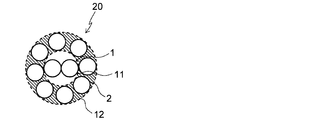
- FIG. 1 is a cross-sectional view of a steel cord for reinforcing rubber articles according to a preferred embodiment of the present invention.
- the steel cord 20 of the present invention is formed by twisting a core 11 composed of two core filaments 1 and seven or eight, preferably eight sheath filaments 2 around the core 11. It has a layer twist structure made of a sheath 12.
- the two core filaments 1 constituting the core 11 are twisted together. By setting it as this structure, it becomes a thing excellent in cut resistance rather than the steel cord formed by twisting together the conventional three core filaments. The reason will be described below.
- FIG. 2 is a cross-sectional view of a steel cord according to a preferred embodiment of the present invention, (a) is a cross-sectional view before cutting input, and (b) is a cross-sectional view at the time of cutting input.
- FIG. 3 is a cross-sectional view of a steel cord having a 1 ⁇ 3 + 8 structure, (a) is a cross-sectional view before cutting input, and (b) is a cross-sectional view at the time of cutting input.
- the steel cord 20 having the core 11 obtained by twisting the two core filaments 1 has many gaps in the core 11. For this reason, the sheath filament 2 can sink into the gap portion of the core 11 when a cut is input, and the cross section can be deformed into a flat shape. Therefore, the cut input can be relaxed and the shear load is increased.
- the steel cord having the core 11 in which the three core filaments 1 are twisted has no gap for the sheath filament 2 to sink into the core 11 at the time of the cut input.
- the cross section cannot be deformed into a flat shape.
- the cut input cannot be relaxed and the shear load is relatively small.
- the core filament is one or four steel cords, there is no gap in which the sheath filament sinks into the core. Therefore, in the steel cord 20 of the present invention, the core 11 is formed by twisting two core filaments 1 together. Further, since the sheath filament can be smoothly subducted, it is preferable to use a straight filament as the core filament and the sheath filament.
- the number of sheath filaments 2 is 7 or 8. If the number of sheath filaments is less than 7, the amount of steel per unit area of the steel cord is small, so that the shear load is reduced. On the other hand, when there are more than eight sheath filaments, the gap between the sheath filaments becomes small and cannot be flattened, resulting in a low shear load. In addition, the gap between the sheath filaments is reduced, which is not preferable because the rubber is less likely to penetrate.
- the gap area S1 of the sheath 12 and the sum S2 of the cross-sectional areas of the sheath filament 2 are expressed by the following formula (1), 40 ⁇ S1 / S2 ⁇ 100 (%) ⁇ 120 (1) It is preferable to satisfy the relationship represented by these.
- the gap area S1 of the sheath 12 refers to a portion indicated by oblique lines in FIG. By setting S1 / S2 ⁇ 100 (%) to 40 or more, the gap area of the sheath 12 can be sufficiently secured, and the steel cord is easily deformed into a flat shape at the time of cutting input.
- the rubber has excellent permeability, and it is possible to satisfactorily prevent a separation failure caused by water entering from cut flaws and corroding the steel cord.
- S1 / S2 ⁇ 100 (%) the amount of steel in the sheath 12 can be secured, and the cut resistance as a reinforcing material can be sufficiently secured.
- the gap area S1 of the sheath 12 can be obtained by the following formula (3).
- S1 (r 1 + r 2 ) 2 ⁇ -r 1 2 ⁇ -r 2 2 ⁇ ⁇ N / 4 (3)
- r 1 Core filament diameter
- r 2 Sheath filament diameter
- N Number of sheath filaments
- the clearance gap area S1 of the sheath 12 is 0.30 mm ⁇ 2 > or more.
- the diameters of the core filament 1 and the sheath filament 2 may be set as appropriate within the range used in ordinary steel cords.
- the wire diameters of the core filament 1 and the sheath filament 2 are the same.
- the diameter of the core filament 1 and the diameter of the sheath filament 2 are adjusted so that the gap area S1 of the sheath 12 is 0.30 mm 2 or more. An effect can be obtained.
- the core filament strength F1 and the sheath filament strength F2 are represented by the following formula (2): F1 / F2 ⁇ 100 ⁇ 90 (%) (2) It is preferable to satisfy the relationship represented by these.
- strength is also required for the belt layer. If this is insufficient, it will not be able to withstand internal pressure and load, and burst durability will be reduced.
- the steel filament is thickened to increase the strength, the penetration rate of rubber into the steel cord will deteriorate.
- the shear load is deteriorated.
- the strength F2 of the sheath filament is 150 N or more, but considering the shear load, the upper limit of F1 and F2 is 580 N or less.
- the steel cord 20 of the present invention is only important to have a core 11 formed by twisting two core filaments 1 and a sheath 12 formed by seven or eight sheath filaments 2 twisted by the core 11.
- the other structures are not particularly limited.
- the twisting pitch of the core filament 1 and the sheath filament 2 may be set as appropriate within the range conventionally employed, and the twisting pitch of the core filament 1 and the twisting pitch of the sheath filament 2 are different even if they are the same. May be.
- the material of the steel filament used for the steel cord 20 of this invention Any can be used if it is conventionally used, but the carbon component is 0.80 mass% or more. Carbon steel is preferred. The effect of the present invention can be obtained satisfactorily by making the filament material a high carbon steel having a high hardness carbon component of 0.80% by mass or more. On the other hand, if the carbon component exceeds 1.5% by mass, the ductility is lowered and the fatigue resistance is inferior.
- the surface of the steel cord 20 of the present invention may be plated.
- the composition of the surface of the steel cord 20 is not particularly limited, but is preferably brass plating made of copper and zinc, and more preferably has a copper content of 60% by mass or more. . Thereby, the adhesiveness of a steel filament and rubber can be improved.
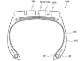
- FIG. 4 shows a cross-sectional view in the width direction of a pneumatic tire according to an embodiment of the present invention.
- the tire 100 of the present invention includes a bead core 101 provided on a pair of right and left bead portions 106, and extends from the crown portion to both bead portions 106 via both sidewall portions 105, and is wound around the bead core 101 to bead.
- the reinforcing material for heavy duty pneumatic tires such as dump trucks, in particular, the outermost layer belt 103c and the outermost layer belt layer 103c in the tire radial direction. It is suitable as a reinforcing material for a belt reinforcing layer (not shown) disposed outside.
- the tire 100 of the present invention there are no particular limitations on the details of the structure and the material of each member, and the tire 100 can be appropriately selected from conventionally known ones.
- a tread pattern is appropriately formed on the surface of the tread portion 104, a bead filler (not shown) is disposed outside the bead core 101 in the tire radial direction, and an inner liner is disposed in the innermost layer of the tire 100.
- an inert gas such as nitrogen.
- Examples 1 to 10 Conventional Example and Comparative Examples 1 to 6>
- Two-layered steel cords having the structures shown in Tables 1 to 3 below were produced.
- the values of the clearance area S1 of the sheath of the sheath filament, the sum S2 of the cross-sectional area, the value of S1 / S2 ⁇ 100, the strength F1 of the core filament, the strength F2 of the sheath filament, and F1 / F2 ⁇ 100 are also shown in the same table.
- the obtained steel cord was evaluated for shear fracture resistance.
- the evaluation method is as follows.
Landscapes
- Engineering & Computer Science (AREA)
- Mechanical Engineering (AREA)
- Ropes Or Cables (AREA)
- Tires In General (AREA)
Abstract
L'invention concerne : un câble d'acier de renforcement d'article en caoutchouc présentant une meilleure résistance à la coupe que des câbles selon l'état de la technique; et un pneumatique l'utilisant. La présente invention concerne un câble d'acier de renforcement d'article en caoutchouc 20 ayant une structure de couche torsadée d'une âme 11, obtenue à partir de deux filaments d'âme 1, et d'une gaine 12 obtenue en tordant ensemble sept ou huit filaments de gaine 2 autour de l'âme 11. Les deux filaments d'âme 1 formant l'âme 11 sont torsadés ensemble.
Applications Claiming Priority (2)
| Application Number | Priority Date | Filing Date | Title |
|---|---|---|---|
| JP2015-026064 | 2015-02-13 | ||
| JP2015026064 | 2015-02-13 |
Publications (1)
| Publication Number | Publication Date |
|---|---|
| WO2016129595A1 true WO2016129595A1 (fr) | 2016-08-18 |
Family
ID=56614650
Family Applications (1)
| Application Number | Title | Priority Date | Filing Date |
|---|---|---|---|
| PCT/JP2016/053827 Ceased WO2016129595A1 (fr) | 2015-02-13 | 2016-02-09 | Câble d'acier de renforcement d'article en caoutchouc et pneumatique l'utilisant |
Country Status (1)
| Country | Link |
|---|---|
| WO (1) | WO2016129595A1 (fr) |
Citations (8)
| Publication number | Priority date | Publication date | Assignee | Title |
|---|---|---|---|---|
| JPS63235587A (ja) * | 1986-11-25 | 1988-09-30 | 横浜ゴム株式会社 | 重荷重用空気入りタイヤ |
| JPH02154086A (ja) * | 1988-12-07 | 1990-06-13 | Bridgestone Corp | ゴム物品補強用スチールコード及び空気入りラジアルタイヤ |
| JPH02306801A (ja) * | 1989-05-22 | 1990-12-20 | Bridgestone Corp | ラジアルタイヤ |
| JPH04193605A (ja) * | 1990-11-28 | 1992-07-13 | Bridgestone Corp | 大型ラジアルタイヤ |
| JPH09143890A (ja) * | 1995-11-17 | 1997-06-03 | Bridgestone Metalpha Kk | タイヤ補強用スチ−ルコ−ド及びそれを用いた空気入りタイヤ |
| JP2001234486A (ja) * | 2000-02-25 | 2001-08-31 | Tokyo Seiko Co Ltd | スチールコード及びゴム複合体 |
| JP2007537083A (ja) * | 2004-05-12 | 2007-12-20 | ソシエテ ド テクノロジー ミシュラン | タイヤ及びタイヤ用の金属/ゴム複合材料 |
| KR101601202B1 (ko) * | 2014-09-23 | 2016-03-21 | 금호타이어 주식회사 | 카카스용 극세선 스틸코드를 가지는 승용차용 래디알 타이어 |
-
2016
- 2016-02-09 WO PCT/JP2016/053827 patent/WO2016129595A1/fr not_active Ceased
Patent Citations (8)
| Publication number | Priority date | Publication date | Assignee | Title |
|---|---|---|---|---|
| JPS63235587A (ja) * | 1986-11-25 | 1988-09-30 | 横浜ゴム株式会社 | 重荷重用空気入りタイヤ |
| JPH02154086A (ja) * | 1988-12-07 | 1990-06-13 | Bridgestone Corp | ゴム物品補強用スチールコード及び空気入りラジアルタイヤ |
| JPH02306801A (ja) * | 1989-05-22 | 1990-12-20 | Bridgestone Corp | ラジアルタイヤ |
| JPH04193605A (ja) * | 1990-11-28 | 1992-07-13 | Bridgestone Corp | 大型ラジアルタイヤ |
| JPH09143890A (ja) * | 1995-11-17 | 1997-06-03 | Bridgestone Metalpha Kk | タイヤ補強用スチ−ルコ−ド及びそれを用いた空気入りタイヤ |
| JP2001234486A (ja) * | 2000-02-25 | 2001-08-31 | Tokyo Seiko Co Ltd | スチールコード及びゴム複合体 |
| JP2007537083A (ja) * | 2004-05-12 | 2007-12-20 | ソシエテ ド テクノロジー ミシュラン | タイヤ及びタイヤ用の金属/ゴム複合材料 |
| KR101601202B1 (ko) * | 2014-09-23 | 2016-03-21 | 금호타이어 주식회사 | 카카스용 극세선 스틸코드를 가지는 승용차용 래디알 타이어 |
Similar Documents
| Publication | Publication Date | Title |
|---|---|---|
| JP6560677B2 (ja) | ゴム物品補強用スチールコード | |
| JP6545942B2 (ja) | ゴム物品補強用スチールコードおよびそれを用いた空気入りタイヤ | |
| JP6400972B2 (ja) | ゴム物品補強用スチールコード | |
| JP5587739B2 (ja) | 空気入りタイヤ | |
| US10895037B2 (en) | Steel cord for reinforcing rubber article | |
| JP7330190B2 (ja) | 超低、低、及び中程度の弾性率を有する2層マルチストランドコード | |
| JP5860336B2 (ja) | ゴム物品補強用スチールコード及びタイヤ | |
| JP6689747B2 (ja) | ゴム物品補強用スチールコード | |
| JP6440206B2 (ja) | 空気入りタイヤ | |
| JP6717701B2 (ja) | タイヤ用スチールコードおよびこれを用いた空気入りタイヤ | |
| JP6683570B2 (ja) | 空気入りタイヤ | |
| EP3444127A1 (fr) | Pneu pour véhicules de construction, et câble d'acier | |
| JP5495412B2 (ja) | ゴム物品補強用スチールコードおよびタイヤ | |
| JP6717702B2 (ja) | 空気入りタイヤ | |
| JP5592127B2 (ja) | ゴム物品補強用スチールコードおよびそれを用いたタイヤ | |
| JP5718087B2 (ja) | 空気入りタイヤ | |
| JP2007296991A (ja) | 大型空気入りラジアルタイヤ | |
| JP2010064688A (ja) | 重荷重用空気入りラジアルタイヤ |
Legal Events
| Date | Code | Title | Description |
|---|---|---|---|
| 121 | Ep: the epo has been informed by wipo that ep was designated in this application |
Ref document number: 16749239 Country of ref document: EP Kind code of ref document: A1 |
|
| NENP | Non-entry into the national phase |
Ref country code: DE |
|
| 122 | Ep: pct application non-entry in european phase |
Ref document number: 16749239 Country of ref document: EP Kind code of ref document: A1 |
|
| NENP | Non-entry into the national phase |
Ref country code: JP |