WO2016139710A1 - Fil de tondeuse, et procédé de fabrication de fil de tondeuse - Google Patents
Fil de tondeuse, et procédé de fabrication de fil de tondeuse Download PDFInfo
- Publication number
- WO2016139710A1 WO2016139710A1 PCT/JP2015/056056 JP2015056056W WO2016139710A1 WO 2016139710 A1 WO2016139710 A1 WO 2016139710A1 JP 2015056056 W JP2015056056 W JP 2015056056W WO 2016139710 A1 WO2016139710 A1 WO 2016139710A1
- Authority
- WO
- WIPO (PCT)
- Prior art keywords
- wire
- mowing cord
- manufacturing
- cord according
- mowing
- Prior art date
- Legal status (The legal status is an assumption and is not a legal conclusion. Google has not performed a legal analysis and makes no representation as to the accuracy of the status listed.)
- Ceased
Links
Images






Classifications
-
- A—HUMAN NECESSITIES
- A01—AGRICULTURE; FORESTRY; ANIMAL HUSBANDRY; HUNTING; TRAPPING; FISHING
- A01D—HARVESTING; MOWING
- A01D34/00—Mowers; Mowing apparatus of harvesters
- A01D34/01—Mowers; Mowing apparatus of harvesters characterised by features relating to the type of cutting apparatus
- A01D34/412—Mowers; Mowing apparatus of harvesters characterised by features relating to the type of cutting apparatus having rotating cutters
- A01D34/416—Flexible line cutters
- A01D34/4168—Constructional details of the flexible lines
-
- A—HUMAN NECESSITIES
- A01—AGRICULTURE; FORESTRY; ANIMAL HUSBANDRY; HUNTING; TRAPPING; FISHING
- A01D—HARVESTING; MOWING
- A01D34/00—Mowers; Mowing apparatus of harvesters
- A01D34/01—Mowers; Mowing apparatus of harvesters characterised by features relating to the type of cutting apparatus
- A01D34/412—Mowers; Mowing apparatus of harvesters characterised by features relating to the type of cutting apparatus having rotating cutters
- A01D34/63—Mowers; Mowing apparatus of harvesters characterised by features relating to the type of cutting apparatus having rotating cutters having cutters rotating about a vertical axis
- A01D34/73—Cutting apparatus
-
- B—PERFORMING OPERATIONS; TRANSPORTING
- B26—HAND CUTTING TOOLS; CUTTING; SEVERING
- B26F—PERFORATING; PUNCHING; CUTTING-OUT; STAMPING-OUT; SEVERING BY MEANS OTHER THAN CUTTING
- B26F1/00—Perforating; Punching; Cutting-out; Stamping-out; Apparatus therefor
- B26F1/02—Perforating by punching, e.g. with relatively-reciprocating punch and bed
- B26F1/12—Perforating by punching, e.g. with relatively-reciprocating punch and bed to notch margins of work
-
- B—PERFORMING OPERATIONS; TRANSPORTING
- B29—WORKING OF PLASTICS; WORKING OF SUBSTANCES IN A PLASTIC STATE IN GENERAL
- B29C—SHAPING OR JOINING OF PLASTICS; SHAPING OF MATERIAL IN A PLASTIC STATE, NOT OTHERWISE PROVIDED FOR; AFTER-TREATMENT OF THE SHAPED PRODUCTS, e.g. REPAIRING
- B29C43/00—Compression moulding, i.e. applying external pressure to flow the moulding material; Apparatus therefor
- B29C43/02—Compression moulding, i.e. applying external pressure to flow the moulding material; Apparatus therefor of articles of definite length, i.e. discrete articles
-
- B—PERFORMING OPERATIONS; TRANSPORTING
- B29—WORKING OF PLASTICS; WORKING OF SUBSTANCES IN A PLASTIC STATE IN GENERAL
- B29C—SHAPING OR JOINING OF PLASTICS; SHAPING OF MATERIAL IN A PLASTIC STATE, NOT OTHERWISE PROVIDED FOR; AFTER-TREATMENT OF THE SHAPED PRODUCTS, e.g. REPAIRING
- B29C43/00—Compression moulding, i.e. applying external pressure to flow the moulding material; Apparatus therefor
- B29C43/02—Compression moulding, i.e. applying external pressure to flow the moulding material; Apparatus therefor of articles of definite length, i.e. discrete articles
- B29C43/021—Compression moulding, i.e. applying external pressure to flow the moulding material; Apparatus therefor of articles of definite length, i.e. discrete articles characterised by the shape of the surface
-
- B—PERFORMING OPERATIONS; TRANSPORTING
- B29—WORKING OF PLASTICS; WORKING OF SUBSTANCES IN A PLASTIC STATE IN GENERAL
- B29C—SHAPING OR JOINING OF PLASTICS; SHAPING OF MATERIAL IN A PLASTIC STATE, NOT OTHERWISE PROVIDED FOR; AFTER-TREATMENT OF THE SHAPED PRODUCTS, e.g. REPAIRING
- B29C43/00—Compression moulding, i.e. applying external pressure to flow the moulding material; Apparatus therefor
- B29C43/22—Compression moulding, i.e. applying external pressure to flow the moulding material; Apparatus therefor of articles of indefinite length
-
- B—PERFORMING OPERATIONS; TRANSPORTING
- B29—WORKING OF PLASTICS; WORKING OF SUBSTANCES IN A PLASTIC STATE IN GENERAL
- B29C—SHAPING OR JOINING OF PLASTICS; SHAPING OF MATERIAL IN A PLASTIC STATE, NOT OTHERWISE PROVIDED FOR; AFTER-TREATMENT OF THE SHAPED PRODUCTS, e.g. REPAIRING
- B29C43/00—Compression moulding, i.e. applying external pressure to flow the moulding material; Apparatus therefor
- B29C43/22—Compression moulding, i.e. applying external pressure to flow the moulding material; Apparatus therefor of articles of indefinite length
- B29C43/222—Compression moulding, i.e. applying external pressure to flow the moulding material; Apparatus therefor of articles of indefinite length characterised by the shape of the surface
-
- B—PERFORMING OPERATIONS; TRANSPORTING
- B29—WORKING OF PLASTICS; WORKING OF SUBSTANCES IN A PLASTIC STATE IN GENERAL
- B29C—SHAPING OR JOINING OF PLASTICS; SHAPING OF MATERIAL IN A PLASTIC STATE, NOT OTHERWISE PROVIDED FOR; AFTER-TREATMENT OF THE SHAPED PRODUCTS, e.g. REPAIRING
- B29C43/00—Compression moulding, i.e. applying external pressure to flow the moulding material; Apparatus therefor
- B29C43/22—Compression moulding, i.e. applying external pressure to flow the moulding material; Apparatus therefor of articles of indefinite length
- B29C43/224—Compression moulding, i.e. applying external pressure to flow the moulding material; Apparatus therefor of articles of indefinite length having a profiled section, e.g. tubes, rods
-
- B—PERFORMING OPERATIONS; TRANSPORTING
- B29—WORKING OF PLASTICS; WORKING OF SUBSTANCES IN A PLASTIC STATE IN GENERAL
- B29C—SHAPING OR JOINING OF PLASTICS; SHAPING OF MATERIAL IN A PLASTIC STATE, NOT OTHERWISE PROVIDED FOR; AFTER-TREATMENT OF THE SHAPED PRODUCTS, e.g. REPAIRING
- B29C43/00—Compression moulding, i.e. applying external pressure to flow the moulding material; Apparatus therefor
- B29C43/22—Compression moulding, i.e. applying external pressure to flow the moulding material; Apparatus therefor of articles of indefinite length
- B29C43/224—Compression moulding, i.e. applying external pressure to flow the moulding material; Apparatus therefor of articles of indefinite length having a profiled section, e.g. tubes, rods
- B29C43/226—Compression moulding, i.e. applying external pressure to flow the moulding material; Apparatus therefor of articles of indefinite length having a profiled section, e.g. tubes, rods having a corrugated section
-
- B—PERFORMING OPERATIONS; TRANSPORTING
- B29—WORKING OF PLASTICS; WORKING OF SUBSTANCES IN A PLASTIC STATE IN GENERAL
- B29C—SHAPING OR JOINING OF PLASTICS; SHAPING OF MATERIAL IN A PLASTIC STATE, NOT OTHERWISE PROVIDED FOR; AFTER-TREATMENT OF THE SHAPED PRODUCTS, e.g. REPAIRING
- B29C48/00—Extrusion moulding, i.e. expressing the moulding material through a die or nozzle which imparts the desired form; Apparatus therefor
-
- B—PERFORMING OPERATIONS; TRANSPORTING
- B29—WORKING OF PLASTICS; WORKING OF SUBSTANCES IN A PLASTIC STATE IN GENERAL
- B29C—SHAPING OR JOINING OF PLASTICS; SHAPING OF MATERIAL IN A PLASTIC STATE, NOT OTHERWISE PROVIDED FOR; AFTER-TREATMENT OF THE SHAPED PRODUCTS, e.g. REPAIRING
- B29C55/00—Shaping by stretching, e.g. drawing through a die; Apparatus therefor
Definitions
- the present invention relates to a mowing cord used for a cord type mowing apparatus.
- a nylon cord that is used by being attached to the outer periphery of a rotating part such as a disk in a mowing apparatus is known (see, for example, JP-A-2007-135418).
- This nylon cord is swung by the rotation of a rotating part to cut off the grass, and is generally spreading instead of a metal rotary blade.
- Nylon cords are not as sharp as metal rotating blades, and even if a human body touches a nylon cord that is turning, there is a low possibility of serious injury. Further, the nylon cord can be replaced according to the condition of breakage or wear, and the replacement is easy.
- the cross section (transverse section) in the direction perpendicular to the axis is square or rhombus, or the unevenness in the longitudinal direction is formed in the cross section (vertical section) in the axial direction.
- Japanese Patent Laid-Open No. 2003-230312 If it does in this way, it will become easy to bite a nylon cord with respect to grass, and the cutting effect of grass will increase.
- Nylon cords may be broken and scattered, or may be discarded after replacement and left on the spot.
- the nylon cord is not naturally decomposed and is left semipermanently. Therefore, from the standpoint of environmental conservation, it has been proposed to use a cord made of a biodegradable plastic that can be naturally decomposed instead of a nylon cord (see, for example, JP 2012-0191913 A).
- Nylon cords are manufactured by extruding a resin raw material and then stretching it. Therefore, in order to make the cross section square or rhombus, the hole shape of the die at the time of extrusion molding may be square or rhombus. However, there is a problem that the unevenness that is continuous in the longitudinal direction of the cord cannot be formed in the extrusion molding and stretching processes.
- a cord manufactured using a biodegradable plastic has a problem that its rigidity is likely to be lowered (that is, soft) as compared with a normal nylon cord. Since the mowing cord is cut while hitting the grass at the time of rotation, a certain degree of rigidity is required. Therefore, when biodegradable plastic is used as a material, there is a concern that the mowing efficiency may be slightly reduced. On the other hand, there is a problem in that the strength of the cord produced using the biodegradable plastic is more likely to be reduced when the unevenness is sheared.
- the present invention has been made in view of the above problems, and an object thereof is to provide a cord for mowing that can dramatically increase the mowing efficiency.
- the present invention for achieving the above object is a method for producing a mowing cord, characterized in that at least a part of the wire is plastically deformed in a direction perpendicular to the axis by pressing a resin wire.
- the cross-sectional shape of the wire may be made into a non-circular shape by the plastic deformation.
- the portion where at least a part of the wire is plastically deformed may have a flat portion that is thinner in the pressing direction than the wire before pressing.
- the portion where at least a part of the wire rod is plastically deformed may have an extending portion that extends radially outward compared to the wire rod before pressing.
- the outer edge in the radial direction of the flat part or the extended part may have a peak extending in the longitudinal direction of the wire.
- a plurality of concavities and convexities that are continuous in the longitudinal direction of the wire may be formed at a site where at least a part of the wire is plastically deformed.
- the unevenness may be formed by excising a part of the plastically deformed portion.
- the wire may be produced by stretching a resin material.
- the cross-section in the direction perpendicular to the axis of the wire may be any one of a circle, an ellipse, a square, and a rhombus.
- the wire may be pressed by a pressing die to plastically deform at least a part of the wire.
- the pressurizing die may have a groove for accommodating the wire, and press the wire while holding the wire by the groove.
- the groove may be in contact with a place inside the width direction of the wire.
- the pressurizing die has a pressing surface continuous to the outside in the width direction of the groove, and presses the wire by the pressing surface while holding the wire by the groove.
- the pressurizing die may have a tapered surface that comes into contact with the wire.
- the present invention which achieves the above object is a mowing cord manufactured by any one of the above manufacturing methods.
- the present invention that achieves the above object comprises a string-like main body portion, and a flat portion that is continuous radially outward from the main body portion and is molded thinner than the main body portion by plastic deformation. This is a mowing cord.
- the flat part may be configured to form a plurality of irregularities along the longitudinal direction of the main body part.
- the unevenness may be formed by cutting a part of the flat part.
- the surface of the flat part may be harder than the surface of the main body part.
- the main body may be a resin material stretched.
- the main body may be characterized in that the cross section in the direction perpendicular to the axis is any one of a circle, an ellipse, a square, and a rhombus.
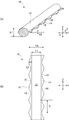
- (A) is the fragmentary perspective view which showed a part of the mowing cord which concerns on this invention
- (B) is the fragmentary top view of the code
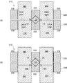
- (A) is a cross-sectional view taken along the line AA in FIG. 3 of the mold, and (B) is a cross-sectional view taken along the line BB in FIG. 3 of the mold.
- (A) is a side view which shows the structure of the metal mold
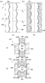
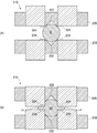
- (A) is front sectional drawing which shows the state of the same metal mold
- (B) is front sectional drawing which shows the state of the same metal mold
- (C) is a front sectional view of the weed cutting cord after the plastic working step is completed.
- (A) is front sectional drawing which shows the state of the same metal mold
- (B) is front sectional drawing which shows the state of the same metal mold
- or (D) is front sectional drawing which shows the other example of the metal mold
- or (D) is front sectional drawing which shows the other example of the metal mold
- (A) And (B) is front sectional drawing which shows the other example of the metal mold
- (A) And (B) is front sectional drawing which shows the other example of the metal mold
- (A) is a plan view showing another example of the mold, (B) is a plane partial sectional view, (C) is a front sectional view taken along line CC of (A), (D) is a front sectional view taken along the line DD of (A).
- or (C) is a front sectional view which shows the aspect which plastically deforms the mowing cord in the cross section of FIG.13 (C), (D) thru
- or (C) is a top view which shows the other example of the cord for the mowing.
- the mowing cord 10 shown in FIG. 1 is used not only for cutting grass such as lawn, camellia, and weed but also for cutting various kinds of vegetation such as bushes and twigs.
- the material of the mowing cord 10 is, for example, a resin, and a typical one is a synthetic resin monofilament.
- the mowing cord 10 includes a cord (cord) -like main body portion 12 and a flat portion 14 that is a portion obtained by plastic deformation and is thinner than the main body portion 12.
- the flat portion 14 is flatter than the wire S (see FIG. 2) before the mowing cord 10 is plastically deformed.
- the flat portion 14 can also be defined as an extending portion that is formed so as to extend outward in the radial direction with respect to the main body portion 12. Therefore, the cross-sectional shape of the mowing cord 10 in the direction perpendicular to the axis becomes a non-circular shape due to plastic deformation.
- the wire S is obtained by stretching a resin material.
- the material of the wire S is, for example, polyamides such as nylon 6, nylon 66, nylon 610 and nylon 11, polyesters such as polyethylene terephthalate and polybutylene terephthalate, polyolefins such as polyethylene and polypropylene, and polyhalogenated carbons such as polyvinylidene chloride. It can be obtained by melt spinning hydrogen, polyether, a copolymer containing these as main components, and drawing.
- biodegradable plastics such as polylactic acid, polycaprolactone, polyhydroxyalkanoate, polyglycolic acid, modified polyvinyl alcohol, casein, modified starch, and PET copolymer can be used.
- the mowing efficiency can be improved by forming the irregularities by processing and hardening the surface by plastic deformation. It is possible to compensate for the shortcomings of the material by increasing. It is also preferable to improve properties such as wear resistance by mixing glass wool into these raw materials.
- the main body 12 has a circular or elliptical cross section, and is approximated to an elliptical shape here.
- the main body 12 is plastically deformed into an elliptical shape by pressurizing the wire S having a circular cross section.
- the thickness (height) X1 of the main body 12 in the pressing direction X is about 3 mm
- the thickness (width) Y1 in the direction perpendicular to the pressing direction X and the longitudinal direction Z (pressure perpendicular direction Y) is about 3 mm. It becomes.
- the flat part 14 protrudes in the pressure perpendicular direction Y with respect to the main body part 12, the thickness (blade thickness) X2 in the pressure direction X is about 1 mm, and the wall thickness (blade width) Y2 in the pressure perpendicular direction Y. Is about 1.5 mm. Therefore, regarding the thickness in the pressing direction X, the flat portion 14 is thinner than the main body portion 12. Further, with respect to the wire S, the plastic deformation amount in the pressing direction X in the flat portion 14 is preferably in the range of about 40% to 95%, and more preferably 40% to 80%. If the plastic deformation is sufficiently performed to this extent, the subsequent shape is difficult to recover to the original shape of the wire S.
- a pair of flat portions 14 are formed so as to be disposed on both outer sides in the pressurizing right-angle direction Y with respect to the main body portion 12, and as a result, the full width YA of the mowing cord 10 in the pressurizing right-angle direction is about 5 mm. .
- the total thickness of the mowing cord 10 in the pressing direction X is 1.2 mm or more and 4 mm or less, preferably 3 mm or less.
- a size of about 1.6 mm is suitable, and for farmland and roadside weeds and weeds, a size of 2.0 mm to 2.6 mm is suitable.
- the weeds and weeds those of 2.4 mm or more and 4 mm or less are preferable, and about 2.4 mm to 3 mm is more preferable.
- the length of the mowing cord 10 is, for example, 200 mm and can be set according to the application. In some cases, a cutting cord 10 of several meters to several tens of meters is used while being cut.
- the flat portion 14 is a portion formed by greatly plastically deforming the wire S, so that the surface thereof is more than the surface of the main body portion 12 due to accumulation of internal strain, for example. Generally hard.
- a plurality of irregularities 16 are formed in the flat portion 14 along the longitudinal direction Z of the main body portion 12.
- the unevenness 16 is a notch recessed in a partial arc shape, and is continuous in the longitudinal direction Z at a predetermined unevenness pitch P.
- the unevenness 16 is formed by cutting (shearing here) the flat portion 14 with a punch or the like.
- FIG. 2 is a flowchart showing a manufacturing process of the mowing cord 10.
- the production process of the mowing cord 10 includes a stirring process (step S100), an extrusion molding process (step S101), a cooling process (step S102), a stretching process (step S103), a heat treatment process (step S104), Winding process (step S105), flexible processing process (step S106), drying process (step S107), plastic working process (step S108), excision working process (step S109), and performance inspection process (step) S110) and a final processing step (step S111).
- the raw material in the container is stirred.
- the stirred raw material is extruded with a die and formed into a thread shape in the extrusion process (step S101).
- the target object formed into a thread shape is cooled in the cooling tank in the cooling step (step S102).
- the cooled object is stretched in the stretching step (step S103).
- the stretched object is heated in the heat treatment step (step S104).
- the heated object is wound around the shaft core in the winding step (step S105).
- the object wound around the shaft core is immersed in a plasticizer and subjected to a softening process in the softening process (step S106).
- the object subjected to the softening process is heated and dried in the drying process (step S107).
- the object subjected to the drying process becomes the wire rod S.
- the wire S is plastically deformed by press working using a pressurizing die to form the main body portion 12 and the flat portion 14, and in the cutting step (step S109), a punching punch is formed.
- the irregularities 16 are formed in the flat portion 14.
- performance inspections such as strength and dimensions are performed.
- the object subjected to the performance inspection is processed as a mowing cord 10 which is a product by cutting it to a desired length in the final processing step (step S111).
- the stretching step (step S103) and the heat treatment step (step S104) may be appropriately repeated a plurality of times before the winding step (step S105). Note that, after the plastic working step (step S108), the material can be further hardened by rapid heating.
- FIG. 3 to 5 show a mold 210 set in the press machine of the processing apparatus 200.
- the mold 210 includes a first pressurizing die 220, a second pressurizing die 230, and a plurality (here, two) punching punches 240.
- the mold 210 forms the flat portion 14 by plastically deforming at least a part of the wire S by sandwiching the wire S with the first pressure die 220 and the second pressure die 230.
- corrugation 16 is formed by excising a part of the flat part 14 of the wire S with the punching punch 240. As shown in FIG.
- a region in which a part of the wire S is plastically deformed is defined as a plastic working region 210 ⁇ / b> A, and a region to be cut by the punching punch 240 is defined as a cutting region 210 ⁇ / b> B.
- the first pressurizing die 220 includes a groove 222 that accommodates at least a part of the wire S, and a pair of pressing surfaces 224 that are continuous on both outer sides in the width direction (pressing right-angle direction Y) of the groove 222. And a punching hole 228 through which the punching punch 240 slides along the pressing direction X.
- the groove 222 mainly holds a part of the wire S so that the wire S does not move during clamping. Of course, the wire S can be plastically deformed by the groove 222.
- the maximum width Mw in the pressure perpendicular direction Y of the groove 222 is set to be smaller than the maximum width Sw (see FIG. 6) of the wire S in the same direction.
- the contact point, tangent line, or tangent surface where the groove 222 is in contact with the wire S (the tangent line 222A or tangent surface 222B (see FIG. 6) in this embodiment) is defined as the width direction of the wire S (this is defined as the pressure perpendicular direction Y). To be set inside.
- the groove 222 of the first pressurizing die 220 has a tapered surface that is inclined with respect to the pressing direction X at the portion that contacts the wire S. That is, the contact surface 222B of the groove 222 becomes a tapered surface inclined at an angle ⁇ with respect to the pressing direction X (see FIG. 6).
- the groove 222 has a pair of contact surfaces 222B, which are tapered surfaces.
- the groove 222 is V-shaped. As shown in FIG. 4B, the distance between the pair of contact surfaces 222B in the direction perpendicular to the pressing direction Y is wide on the pressing side (for example, M1) in the pressing direction X and opposite to the pressing direction (for example, M2). Becomes narrower.
- the axis of the wire S can be centered in the longitudinal direction Z. Since the wire S is always curved in the stretching process or the like, the processing accuracy can be greatly increased by plastic deformation while performing centering.
- the pressing surfaces 224 arranged on both sides of the groove 222 are inclined at an angle ⁇ with respect to the pressing direction X (see FIG. 6), and this angle ⁇ is larger than the angle ⁇ of the contact surface 222B of the groove 222. .
- the angle ⁇ is 90 °, which is a plane perpendicular to the pressing direction X.
- the pressing surface 224 is plastically deformed so as to crush a part of the strand S to form the flat portion 14.
- the flat portion 14 is a flat plate perpendicular to the pressing direction X.
- the second pressurizing die 230 includes a groove 232 that houses at least a part of the wire S, a pair of pressing surfaces 234 that are continuous on both outer sides in the width direction (pressing right-angle direction Y) of the groove 232, and the pressing direction X. It has a sliding hole 238 along which the punching punch 240 slides.
- the groove 232 accommodates a part of the wire S to hold the wire S so that it does not move at the time of clamping, and plastically deforms the wire S.
- the maximum width Mw of the groove 232 in the direction perpendicular to the pressure Y is set to be smaller than the maximum width Sw (see FIG. 6) of the wire S in the same direction.
- the contact point, tangent line or contact surface (in this embodiment, the tangent line 232A or the contact surface 232B) where the groove 232 comes into contact with the wire S is set inside the width direction (pressing right-angle direction Y) of the wire S.
- the groove 232 of the second pressurizing die 230 has a tapered surface that is inclined with respect to the pressing direction X at the portion that contacts the wire S. That is, the contact surface 232B of the groove 232 becomes a tapered surface inclined at an angle ⁇ with respect to the pressing direction X (see FIG. 6).
- the groove 232 has a pair of contact surfaces 232B, and each is a tapered surface.
- the groove 222 is V-shaped. As shown in FIG. 4B, the space between the pair of contact surfaces 232B in the direction perpendicular to the pressing direction Y is wide on the pressing side (for example, M1) in the pressing direction X and opposite to the pressing side in the pressing direction X (for example, M2).
- the axis of the wire S can be centered in the longitudinal direction Z. Since the wire S is always curved in the stretching process or the like, the processing accuracy can be greatly increased by plastic deformation while performing centering.
- the pressing surfaces 234 arranged on both sides of the groove 232 are inclined at an angle ⁇ with respect to the pressing direction X (see FIG. 6), and this angle ⁇ is larger than the angle ⁇ of the contact surface 232B of the groove 232. Become. Incidentally, in the present embodiment, the angle ⁇ is 90 ° and is a plane perpendicular to the pressing direction X.
- the pressing surface 234 is plastically deformed so as to crush a part of the wire S to form the flat portion 14.
- the grooves 222 and 232 of the first pressurizing die 220 and the second pressurizing die 230 have similar shapes, but the present invention is not limited to this.
- one die may be flat.
- the punching punch 240 is installed in the sliding hole 228 of the first pressurizing die 220 and can reciprocate in the pressurizing direction X.
- the tip thereof enters the sliding hole 238 of the second pressurizing punch 240 (see FIG. 7). Since the tip of the punching punch 240 and the sliding hole 238 intersect, a part of the flat portion 14 of the strand S is sheared. Since the punching punch 240 has a cylindrical shape, the unevenness 16 formed in the flat portion 14 has a partial arc shape. Further, the pair of punching punches 240 are arranged at intervals on both outer sides of the grooves 222 and 223. As shown in FIG.
- the inner distance F between the pair of punching punches 240 is set to be equal to or greater than the maximum width Mw of the grooves 222 and 232 and is set to be smaller than the width Sw of the wire S.
- the pair of punching punches 240 is shifted in the longitudinal direction Z by a semi-concave pitch (0.5 P).
- a plurality of punching punches 240 are arranged in the longitudinal direction Z, or if the shape of the punch tip is devised so that a plurality of irregularities 16 can be formed with a single punching punch, the feed amount of the wire S once. Can be increased.
- the wire S When the wire S is inserted into the plastic working region 210A of the grooves 222 and 232 of the mold 210 and the first pressurizing die 220 and the second pressurizing die 230 of the mold 210 are brought close to each other by a press machine (not shown). As shown in FIG. 6 (A), the wire S is held by the grooves 222 and 232. At this time, since the pair of contact surfaces 222B and 232B of the grooves 222 and 232 are tapered surfaces inclined in a V-shaped cross section, the wire S is centered along the longitudinal direction Z. Since the maximum width Mw of the grooves 222 and 232 is smaller than the maximum width S2 of the wire S, a part of the wire S protrudes from the grooves 222 and 232 in the width direction.
- the wire S is compressed by the grooves 222 and 232 while being pressed by the pressing surfaces 224 and 234 as shown in FIG.
- a part of the side surface of the wire S is crushed and expanded / stretched in the direction Y in the pressure perpendicular direction.
- FIG. 3 when this pressurization is repeated while moving the strand S in the longitudinal direction Z for each pit P, grooves 222 and 232 are formed in the wire S as shown in FIG.
- the region (which may be plastically deformed) held in the body becomes the main body portion 12, and the region deformed by being plastically pressed by the pressing surfaces 224 and 234 becomes the flat portion 14.
- the main body 12 is a perfect circle or an ellipse, and the flat part 14 is a plate.
- the first pressurizing die 220 and the second pressurizing die 230 are close to each other, that is, the strand S is in the groove 222.
- the punching punch 240 moves up and down while being held and centered by 232.
- the flat portion 14 is cut into a partial arc shape to form the unevenness 16, and the cut piece 16 ⁇ / b> A falls from the sliding hole 238.
- the multiple uneven portions 16 of the flat portion 14 are formed.
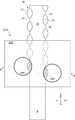
- the mowing apparatus 20 to which the mowing cord 10 is attached will be described with reference to FIG. FIG. 8 shows a state where the mowing cord 10 is attached to the mowing device 20.
- the mowing apparatus 20 includes a handle 21 serving as a handle portion, a handle 22 having a base end portion attached to the handle 21, a disc 23 rotatably attached to a tip portion of the handle 22, and the disc 23.
- a power source (not shown) such as a motor to be rotated is provided.
- One or a plurality of mowing cords 10 are attached to the outer periphery of the disk 23 in a replaceable manner. The mowing cord 10 turns by the rotation of the disk 23 to cut off the grass.
- the mowing cord 10 of the present embodiment includes the string-shaped main body 12 and the flat portion 14 that is extended and formed by plastic deformation radially outward with respect to the main body 12. Due to this plastic deformation, the cross-sectional shape becomes a non-circular shape, so that the mowing cord 10 can easily bite into the grass.
- the flat part 14 since the flat part 14 becomes flat, it functions as a so-called cutting edge, easily bites into the grass, and can be cut efficiently.
- the flat part 14 can harden the surface by cold (normal temperature) plastic working. As a result, the cutting efficiency can be further increased, and at the same time, the wear resistance is increased, so that the life of the mowing cord 10 can be extended.
- the cord for mowing 10 is formed by cutting a part of the flat part 14 to form a plurality of irregularities 16 along the longitudinal direction Z.
- the unevenness 16 when the unevenness 16 is caught on the grass, it can be cut like a so-called saw blade.
- the flat portion 14 whose surface has been hardened by plastic deformation is cut out by shearing to form the unevenness 16, so that the cross section of the unevenness 16 becomes hard and tends to bite into the grass.
- the unevenness 16 serving as a pseudo saw blade is thin, extremely efficient mowing can be realized.
- the main body 12 can maintain flexibility as an originally stretched strand. It is also advantageous that the surface-cured flat portion 14 has a volume smaller than the volume of the main body portion 12. As a result, the entire mowing cord 10 can be secured without being broken or broken. In addition, since the unevenness 16 (blade edge) can be locally hardened, it is possible to achieve both long life and improved mowing efficiency.
- the first and second pressing dies 220 and 230 pressurize while holding the wire S by the grooves 222 and 232, so that the shape accuracy of plastic deformation can be improved. Further, since the contact, tangent or contact surface where the grooves 222 and 232 are in contact with the wire S is set on the inner side in the width direction of the wire S, when the wire S is pressurized by these contact, tangent or contact surface, The wire S is spread in the direction Y in the direction perpendicular to the pressure. Accordingly, a part of the wire S can flow in the pressure-perpendicular direction Y and move to the flat portion 14 side.
- the portions of the pressurizing dies 220 and 230 that come into contact with the wire S are tapered surfaces that are inclined with respect to the pressing direction. Therefore, the shape accuracy of the mowing cord 10 can be further improved.
- the pressing dies 220 and 230 have pressing surfaces 224 and 234 that continue to the outside in the width direction of the grooves 222 and 232, the pressing surfaces 224 and 234 hold the wire S by the grooves 222 and 232. Since a part of the wire S can be pressed, the flat part 14 is cold-worked (room temperature) thinner than the main body 12 by the pressing surfaces 224 and 234 while the main body 12 remains thick by the grooves 222 and 232. it can.
- the cross-sectional shape of the wire S is a perfect circle.
- twist may generally occur.
- it can be plastically deformed without returning the twist. That is, the plastic deformation is further performed in the twisted state, and as a result, it is not affected by the twist.
- the flat portion 14 is formed by the punching punch 240. Positioning when the irregularities 16 are formed on the substrate is facilitated.
- the first pressurizing die and the punching punch are integrated, it is possible to further increase the positioning accuracy.
- the cross-sectional shape is passed through a die whose hole shape becomes a diamond shape on the spot.
- the flat portion is not plastically deformed at room temperature due to the pinching pressure.
- the cord is likely to be twisted or bent. Therefore, in another process after that, it becomes difficult to perform positioning when processing the unevenness with respect to the flat portion, and there is also a drawback that the working efficiency is extremely lowered.
- the cord 10 for mowing was manufactured using the wire S which a cross section becomes a perfect circle
- this invention is not limited to this.
- a wire S having a square cross section or a cross-sectional rhombus can be used.
- the other diagonal K2 is plastically deformed by the pressing surfaces 224 and 234, and the flat portion is formed. 14 can be configured.
- the grooves 222 and 232 have a V-shaped cross section
- the cross sections of the grooves 222 and 232 may be a partial regular circular arc or a partial elliptical arc.
- the wire S When the wire S is pressed by these contact points, tangents, or contact surfaces, the wire S is expanded in the pressurization right-angle direction Y. Therefore, a part of the wire S can spread outside the grooves 222 and 232 in the direction perpendicular to the pressure Y, and the flat portion 14 can be configured.
- the flat portion 14 that expands in the direction perpendicular to the pressure Y is formed by plastically deforming the wire S by the pressing surfaces 224 and 234 is illustrated, but the present invention is not limited thereto.
- slits 222S and 232S extending in the pressing direction X are formed in the deepest portions of the grooves 222 and 232 having a V-shaped cross section, and the wire S is formed.
- the flat part 15 which expands in the pressurization direction X can be comprised by flowing a part of material into these slits 222S and 232S.
- the pressing surfaces 224 and 234 are formed outside the grooves 222 and 232, and the flat portions 14 are formed by plastically deforming the wire S by the pressing surfaces 224 and 234.
- the invention is not limited to this.
- the maximum width Mw in the pressure perpendicular direction Y of the grooves 222 and 232 having a V-shaped cross section is made larger than that of the wire S, and the grooves 222 and 232 are formed.
- the cross section can be formed into a rhombus.
- the flat part 15 in which the wire S is flattened in the pressurizing direction X can be configured as compared with the wire S before clamping.
- the flat portion 15 may be defined as an extending portion that is expanded outwardly in the pressurization right-angle direction Y by Mk with respect to the dimension Sw in the pressurization right-angle direction Y of the wire S before clamping.
- Concavities and convexities 16 may be formed on the flat portion 15 by a punching punch 240.
- the plastic working region 210A and the cutting region 210B are separately provided in the mold 210 (see FIG. 3) is illustrated, but the present invention is not limited to this.
- punching punches 240 and 241 are installed on both the first pressurizing die 220 and the second pressurizing die 230, and the distal end surfaces 240A and 241A plasticize the wire S. It can also serve as a part of the pressing surfaces 224 and 234 to be deformed.
- the flat portion 14 is formed by crushing the wire S by the tip surfaces 240A and 241A of the punching punches 240 and 241, and continuously, as shown in FIG. 11B, the punching punches 240 and 241 are formed. By moving, the flat portion 14 can be excised and the irregularities 16 can be formed. As a result, in the mold 210, the plastic working region and the cutting region are provided at the same place.
- a cutter blade 248 along the tip shape of the concavo-convex 16 is formed on at least one of the first pressurizing die 220 and the second pressurizing die 230, and the cutter blade 248 adds the cutter blade 248.
- Concavities and convexities 16 can be excised simultaneously with plastic deformation by pressure.
- the present invention is not limited to this.
- a side wall 250 is prepared in advance along the uneven tip (peak) shape of the mowing cord 10, and the first pressure die 220 and the second pressure die are prepared.
- the shape of the edge in the width direction of the pressing surfaces 224 and 234 of 230 is also made to match the tip (peak) shape of the unevenness of the mowing cord 10.
- the first pressing die 220 and the second pressing die 230 are moved along the side wall 250.
- FIGS. 14A to 14C and FIGS. 14D to 14F the space surrounded by the pressing surfaces 224 and 234 and the side wall 250 has a flat portion 14 with irregularities 16.
- the unevenness 16 can be formed simultaneously by plastic deformation.
- the pressing surfaces 224 and 234 may be configured so as to be convex on the inner side in the pressurizing direction Y (that is, on the wire S side).
- the pressing surfaces 224 and 234 are brought close to each other, thereby part of the wire S Plastically deformed to pinch.
- a portion of the wire rod S is spread outward in the pressurizing right-angle direction Y, so that a flat portion 14 that protrudes outward in the pressurizing perpendicular direction Y is formed.
- the unevenness 16 continuous in the longitudinal direction is simultaneously completed depending on the shape of the flat portions 14 (see FIG. 5).
- the shape of the unevenness 16 is exemplified by a partial arc shape that protrudes inward in FIG. 1, but the shape of the unevenness 16 can be variously selected.
- a V-shaped peak or valley may be continuous or a saw blade shape, or as shown in FIG. 17B, a partial arc shape that protrudes outward may be used.
- the main body 12 may be processed so that a part of the unevenness 16 is included.
- corrugation 16 was formed in the said embodiment in the direction in which the width
- the unevenness 16 can be formed so as to be displaced in the pressing direction X by plastically deforming the flat portion 14.
- plastic working region 210A and the cutting region 210B are integrally configured in one mold is illustrated, but it is also possible to process with a separate machine (mold).
- the present invention is not limited to this.
- the cutting process may be performed first so as to form irregularities on the strands, and then the plastic working process may be performed on the irregularities to extend the irregularities in the diameter direction.
Landscapes
- Engineering & Computer Science (AREA)
- Mechanical Engineering (AREA)
- Life Sciences & Earth Sciences (AREA)
- Environmental Sciences (AREA)
- Forests & Forestry (AREA)
- Harvester Elements (AREA)
- Wire Processing (AREA)
- Shaping Of Tube Ends By Bending Or Straightening (AREA)
Abstract
Priority Applications (6)
| Application Number | Priority Date | Filing Date | Title |
|---|---|---|---|
| PCT/JP2015/056056 WO2016139710A1 (fr) | 2015-03-02 | 2015-03-02 | Fil de tondeuse, et procédé de fabrication de fil de tondeuse |
| JP2017503219A JP6453438B2 (ja) | 2015-03-02 | 2015-03-02 | 草刈り用コード、草刈り用コード製造方法 |
| US15/553,866 US10945365B2 (en) | 2015-03-02 | 2015-03-02 | Mower cord and manufacturing method for mower cord |
| CN201580077015.0A CN107404840A (zh) | 2015-03-02 | 2015-03-02 | 割草用绳、割草用绳制造方法 |
| CN202211093423.3A CN115366309A (zh) | 2015-03-02 | 2015-03-02 | 割草用绳的制造方法及割草用绳的制造装置 |
| US17/108,402 US11510363B2 (en) | 2015-03-02 | 2020-12-01 | Mower cord and manufacturing method for mower cord |
Applications Claiming Priority (1)
| Application Number | Priority Date | Filing Date | Title |
|---|---|---|---|
| PCT/JP2015/056056 WO2016139710A1 (fr) | 2015-03-02 | 2015-03-02 | Fil de tondeuse, et procédé de fabrication de fil de tondeuse |
Related Child Applications (2)
| Application Number | Title | Priority Date | Filing Date |
|---|---|---|---|
| US15/553,866 A-371-Of-International US10945365B2 (en) | 2015-03-02 | 2015-03-02 | Mower cord and manufacturing method for mower cord |
| US17/108,402 Continuation US11510363B2 (en) | 2015-03-02 | 2020-12-01 | Mower cord and manufacturing method for mower cord |
Publications (1)
| Publication Number | Publication Date |
|---|---|
| WO2016139710A1 true WO2016139710A1 (fr) | 2016-09-09 |
Family
ID=56849328
Family Applications (1)
| Application Number | Title | Priority Date | Filing Date |
|---|---|---|---|
| PCT/JP2015/056056 Ceased WO2016139710A1 (fr) | 2015-03-02 | 2015-03-02 | Fil de tondeuse, et procédé de fabrication de fil de tondeuse |
Country Status (4)
| Country | Link |
|---|---|
| US (2) | US10945365B2 (fr) |
| JP (1) | JP6453438B2 (fr) |
| CN (2) | CN115366309A (fr) |
| WO (1) | WO2016139710A1 (fr) |
Cited By (1)
| Publication number | Priority date | Publication date | Assignee | Title |
|---|---|---|---|---|
| KR102187535B1 (ko) * | 2020-07-24 | 2020-12-07 | 주식회사 에스엠유니트 | 탄소섬유실이 포함된 예초기 커팅줄 |
Families Citing this family (10)
| Publication number | Priority date | Publication date | Assignee | Title |
|---|---|---|---|---|
| WO2016139710A1 (fr) * | 2015-03-02 | 2016-09-09 | 三洋テグス株式会社 | Fil de tondeuse, et procédé de fabrication de fil de tondeuse |
| CA3031129C (fr) * | 2018-02-05 | 2025-06-17 | Tritana Intellectual Property Ltd. | Lame de coupe |
| AT522248A1 (de) * | 2019-02-26 | 2020-09-15 | Boehlerit Gmbh & Co Kg | Einsatz aus Hartmetall für eine landwirtschaftliche Vorrichtung |
| US12219896B2 (en) | 2019-03-28 | 2025-02-11 | Aero-Flex Technologies, Inc. | Trimmer line blade |
| US11464162B2 (en) * | 2019-03-28 | 2022-10-11 | Aero-Flex Technologies, Inc. | Reversible line blades |
| USD1013469S1 (en) | 2019-03-28 | 2024-02-06 | Aero-Flex Technologies, Inc. | Trimmer line blade |
| US11311922B2 (en) * | 2020-02-18 | 2022-04-26 | Winn Applied Material Inc. | Wire drawing process of light storage wire |
| EP3935932A1 (fr) * | 2020-07-07 | 2022-01-12 | Andreas Stihl AG & Co. KG | Lame de coupe pour une tête de coupe et tête de coupe pour une débroussailleuse |
| ES2906676A1 (es) * | 2020-10-15 | 2022-04-19 | Int S A | Procedimiento de fabricacion monofilamento de corte perfil oval retorcido |
| CN112482058B (zh) * | 2020-11-27 | 2023-06-02 | 广东康派环创科技有限公司 | 圆绳印花方法 |
Citations (5)
| Publication number | Priority date | Publication date | Assignee | Title |
|---|---|---|---|---|
| US4186239A (en) * | 1976-12-06 | 1980-01-29 | Berkley & Company, Inc. | Monofilament weed cutters |
| JPH0633780Y2 (ja) * | 1989-10-26 | 1994-09-07 | 株式会社ゴーセン | 刈払用ナイロンコード |
| JP2005528900A (ja) * | 2002-06-07 | 2005-09-29 | スピード、フランス | 植物切断装置のための新規な切断ユニットおよび新規な切断フィラメント |
| JP3149886U (ja) * | 2009-02-06 | 2009-04-16 | 三洋テグス株式会社 | 草刈り用ナイロンコード |
| JP2012191913A (ja) * | 2011-03-18 | 2012-10-11 | Sanyo Tegusu Co Ltd | 草刈り用コード |
Family Cites Families (11)
| Publication number | Priority date | Publication date | Assignee | Title |
|---|---|---|---|---|
| US4869055A (en) * | 1987-01-23 | 1989-09-26 | Omark Industries, Inc. | Star-shaped flexible cutting line |
| US4858457A (en) * | 1988-05-12 | 1989-08-22 | Potucek Frank R | Machine and method for making concrete reinforcing bars |
| WO1997043469A1 (fr) | 1996-05-10 | 1997-11-20 | Klaus Bloch | Procede et dispositif pour produire un fil de fauchage |
| JP2003230312A (ja) | 2002-02-08 | 2003-08-19 | Hitachi Koki Co Ltd | 草刈りコードカッタ |
| WO2005077143A1 (fr) * | 2004-01-19 | 2005-08-25 | Speed France | Procede de fabrication de filaments de coupe de vegetaux ayant de nouvelles proprietes, et filaments ayant de telles proprietes |
| US20050172501A1 (en) * | 2004-02-10 | 2005-08-11 | Robert L. Phillips (50%) | Trimmer line and method of manufacture |
| JP2007135418A (ja) | 2005-11-15 | 2007-06-07 | Cal Enterprise Kk | 刈払用プラスチック製抜け止め付きコード |
| EP2288249B1 (fr) | 2008-04-11 | 2016-12-21 | Speed France S.A.S. | Filament de coupe d'une composition améliorée pour taille-bordure, débroussailleuses et autres |
| CN201479592U (zh) * | 2009-08-28 | 2010-05-26 | 耀亿工业股份有限公司 | 可分解的割草线 |
| CN201947663U (zh) * | 2011-03-11 | 2011-08-31 | 温州市瑞昌特种单丝厂(普通合伙) | 割草机用割草线 |
| WO2016139710A1 (fr) * | 2015-03-02 | 2016-09-09 | 三洋テグス株式会社 | Fil de tondeuse, et procédé de fabrication de fil de tondeuse |
-
2015
- 2015-03-02 WO PCT/JP2015/056056 patent/WO2016139710A1/fr not_active Ceased
- 2015-03-02 JP JP2017503219A patent/JP6453438B2/ja active Active
- 2015-03-02 CN CN202211093423.3A patent/CN115366309A/zh active Pending
- 2015-03-02 US US15/553,866 patent/US10945365B2/en active Active
- 2015-03-02 CN CN201580077015.0A patent/CN107404840A/zh active Pending
-
2020
- 2020-12-01 US US17/108,402 patent/US11510363B2/en active Active
Patent Citations (5)
| Publication number | Priority date | Publication date | Assignee | Title |
|---|---|---|---|---|
| US4186239A (en) * | 1976-12-06 | 1980-01-29 | Berkley & Company, Inc. | Monofilament weed cutters |
| JPH0633780Y2 (ja) * | 1989-10-26 | 1994-09-07 | 株式会社ゴーセン | 刈払用ナイロンコード |
| JP2005528900A (ja) * | 2002-06-07 | 2005-09-29 | スピード、フランス | 植物切断装置のための新規な切断ユニットおよび新規な切断フィラメント |
| JP3149886U (ja) * | 2009-02-06 | 2009-04-16 | 三洋テグス株式会社 | 草刈り用ナイロンコード |
| JP2012191913A (ja) * | 2011-03-18 | 2012-10-11 | Sanyo Tegusu Co Ltd | 草刈り用コード |
Cited By (1)
| Publication number | Priority date | Publication date | Assignee | Title |
|---|---|---|---|---|
| KR102187535B1 (ko) * | 2020-07-24 | 2020-12-07 | 주식회사 에스엠유니트 | 탄소섬유실이 포함된 예초기 커팅줄 |
Also Published As
| Publication number | Publication date |
|---|---|
| US10945365B2 (en) | 2021-03-16 |
| CN107404840A (zh) | 2017-11-28 |
| US11510363B2 (en) | 2022-11-29 |
| US20210092898A1 (en) | 2021-04-01 |
| CN115366309A (zh) | 2022-11-22 |
| US20180064026A1 (en) | 2018-03-08 |
| JPWO2016139710A1 (ja) | 2018-02-01 |
| JP6453438B2 (ja) | 2019-01-16 |
Similar Documents
| Publication | Publication Date | Title |
|---|---|---|
| JP6453438B2 (ja) | 草刈り用コード、草刈り用コード製造方法 | |
| US8216497B2 (en) | Tissue holding devices and methods for making the same | |
| CN108471844B (zh) | 成形面连接件、成形面连接件的制造方法、以及成形装置 | |
| US3329998A (en) | Apparatus for the production of extruded articles with bristles or spikes | |
| CN1108126C (zh) | 用于圆整人造棕毛端部的装置 | |
| EP1236441B1 (fr) | Alésoir dentaire | |
| KR20040096640A (ko) | 균일한 인장 망의 일단계 회전 성형 | |
| CN102294290A (zh) | 碎纸机刀具及其加工方法 | |
| US4655986A (en) | Blow molded tubing with special holes and method of making same | |
| CN213047092U (zh) | 异形医用手术线 | |
| CN200942527Y (zh) | 组合式双刀刃旋转电动剃须刀刀头 | |
| JP2010042440A (ja) | 溝付きボルトの製造方法 | |
| JPH08141228A (ja) | 電気カミソリの外刃の製造方法 | |
| JP4605517B2 (ja) | 袋ナットの製造方法 | |
| JP4004980B2 (ja) | 繊維配向押出装置 | |
| US7900360B2 (en) | Cutter assembly and method of producing same | |
| CN113194844B (zh) | 制造具有再成形减小直径末端的外科缝合线的系统、装置和方法 | |
| CN205377591U (zh) | 一种漆包线段切尖头装置 | |
| JP4352058B2 (ja) | 造粒装置用切断装置 | |
| KR102738502B1 (ko) | 봉합사에 바브를 가공하는 장치 | |
| JP2000301487A (ja) | カッター装置 | |
| CN217047069U (zh) | 塑料母粒生产用切粒刀具 | |
| JP2013170229A (ja) | 固形燃料棒およびその製造装置 | |
| JP6732180B2 (ja) | 草刈り用コード及びその製造方法 | |
| RU2240201C2 (ru) | Способ изготовления болтов с зачищающими выемками на стержне |
Legal Events
| Date | Code | Title | Description |
|---|---|---|---|
| 121 | Ep: the epo has been informed by wipo that ep was designated in this application |
Ref document number: 15883880 Country of ref document: EP Kind code of ref document: A1 |
|
| ENP | Entry into the national phase |
Ref document number: 2017503219 Country of ref document: JP Kind code of ref document: A |
|
| WWE | Wipo information: entry into national phase |
Ref document number: 15553866 Country of ref document: US |
|
| NENP | Non-entry into the national phase |
Ref country code: DE |
|
| 122 | Ep: pct application non-entry in european phase |
Ref document number: 15883880 Country of ref document: EP Kind code of ref document: A1 |