WO2016140345A1 - Dispositif et procédé de commande de mécanisme d'entraînement de vehicule - Google Patents
Dispositif et procédé de commande de mécanisme d'entraînement de vehicule Download PDFInfo
- Publication number
- WO2016140345A1 WO2016140345A1 PCT/JP2016/056809 JP2016056809W WO2016140345A1 WO 2016140345 A1 WO2016140345 A1 WO 2016140345A1 JP 2016056809 W JP2016056809 W JP 2016056809W WO 2016140345 A1 WO2016140345 A1 WO 2016140345A1
- Authority
- WO
- WIPO (PCT)
- Prior art keywords
- stopper
- sensor
- learning
- limit value
- output
- Prior art date
- Legal status (The legal status is an assumption and is not a legal conclusion. Google has not performed a legal analysis and makes no representation as to the accuracy of the status listed.)
- Ceased
Links
Images




Classifications
-
- F—MECHANICAL ENGINEERING; LIGHTING; HEATING; WEAPONS; BLASTING
- F02—COMBUSTION ENGINES; HOT-GAS OR COMBUSTION-PRODUCT ENGINE PLANTS
- F02B—INTERNAL-COMBUSTION PISTON ENGINES; COMBUSTION ENGINES IN GENERAL
- F02B75/00—Other engines
- F02B75/04—Engines with variable distances between pistons at top dead-centre positions and cylinder heads
- F02B75/048—Engines with variable distances between pistons at top dead-centre positions and cylinder heads by means of a variable crank stroke length
-
- F—MECHANICAL ENGINEERING; LIGHTING; HEATING; WEAPONS; BLASTING
- F02—COMBUSTION ENGINES; HOT-GAS OR COMBUSTION-PRODUCT ENGINE PLANTS
- F02B—INTERNAL-COMBUSTION PISTON ENGINES; COMBUSTION ENGINES IN GENERAL
- F02B75/00—Other engines
- F02B75/04—Engines with variable distances between pistons at top dead-centre positions and cylinder heads
- F02B75/045—Engines with variable distances between pistons at top dead-centre positions and cylinder heads by means of a variable connecting rod length
-
- F—MECHANICAL ENGINEERING; LIGHTING; HEATING; WEAPONS; BLASTING
- F01—MACHINES OR ENGINES IN GENERAL; ENGINE PLANTS IN GENERAL; STEAM ENGINES
- F01L—CYCLICALLY OPERATING VALVES FOR MACHINES OR ENGINES
- F01L13/00—Modifications of valve-gear to facilitate reversing, braking, starting, changing compression ratio, or other specific operations
-
- F—MECHANICAL ENGINEERING; LIGHTING; HEATING; WEAPONS; BLASTING
- F02—COMBUSTION ENGINES; HOT-GAS OR COMBUSTION-PRODUCT ENGINE PLANTS
- F02B—INTERNAL-COMBUSTION PISTON ENGINES; COMBUSTION ENGINES IN GENERAL
- F02B75/00—Other engines
- F02B75/32—Engines characterised by connections between pistons and main shafts and not specific to preceding main groups
-
- F—MECHANICAL ENGINEERING; LIGHTING; HEATING; WEAPONS; BLASTING
- F02—COMBUSTION ENGINES; HOT-GAS OR COMBUSTION-PRODUCT ENGINE PLANTS
- F02D—CONTROLLING COMBUSTION ENGINES
- F02D13/00—Controlling the engine output power by varying inlet or exhaust valve operating characteristics, e.g. timing
- F02D13/02—Controlling the engine output power by varying inlet or exhaust valve operating characteristics, e.g. timing during engine operation
-
- F—MECHANICAL ENGINEERING; LIGHTING; HEATING; WEAPONS; BLASTING
- F02—COMBUSTION ENGINES; HOT-GAS OR COMBUSTION-PRODUCT ENGINE PLANTS
- F02D—CONTROLLING COMBUSTION ENGINES
- F02D15/00—Varying compression ratio
- F02D15/02—Varying compression ratio by alteration or displacement of piston stroke
-
- F—MECHANICAL ENGINEERING; LIGHTING; HEATING; WEAPONS; BLASTING
- F02—COMBUSTION ENGINES; HOT-GAS OR COMBUSTION-PRODUCT ENGINE PLANTS
- F02D—CONTROLLING COMBUSTION ENGINES
- F02D41/00—Electrical control of supply of combustible mixture or its constituents
- F02D41/24—Electrical control of supply of combustible mixture or its constituents characterised by the use of digital means
- F02D41/2406—Electrical control of supply of combustible mixture or its constituents characterised by the use of digital means using essentially read only memories
- F02D41/2425—Particular ways of programming the data
- F02D41/2429—Methods of calibrating or learning
- F02D41/2451—Methods of calibrating or learning characterised by what is learned or calibrated
- F02D41/2474—Characteristics of sensors
-
- F—MECHANICAL ENGINEERING; LIGHTING; HEATING; WEAPONS; BLASTING
- F02—COMBUSTION ENGINES; HOT-GAS OR COMBUSTION-PRODUCT ENGINE PLANTS
- F02D—CONTROLLING COMBUSTION ENGINES
- F02D45/00—Electrical control not provided for in groups F02D41/00 - F02D43/00
-
- G—PHYSICS
- G05—CONTROLLING; REGULATING
- G05B—CONTROL OR REGULATING SYSTEMS IN GENERAL; FUNCTIONAL ELEMENTS OF SUCH SYSTEMS; MONITORING OR TESTING ARRANGEMENTS FOR SUCH SYSTEMS OR ELEMENTS
- G05B13/00—Adaptive control systems, i.e. systems automatically adjusting themselves to have a performance which is optimum according to some preassigned criterion
- G05B13/02—Adaptive control systems, i.e. systems automatically adjusting themselves to have a performance which is optimum according to some preassigned criterion electric
- G05B13/0265—Adaptive control systems, i.e. systems automatically adjusting themselves to have a performance which is optimum according to some preassigned criterion electric the criterion being a learning criterion
-
- F—MECHANICAL ENGINEERING; LIGHTING; HEATING; WEAPONS; BLASTING
- F01—MACHINES OR ENGINES IN GENERAL; ENGINE PLANTS IN GENERAL; STEAM ENGINES
- F01L—CYCLICALLY OPERATING VALVES FOR MACHINES OR ENGINES
- F01L2800/00—Methods of operation using a variable valve timing mechanism
- F01L2800/09—Calibrating
-
- F—MECHANICAL ENGINEERING; LIGHTING; HEATING; WEAPONS; BLASTING
- F02—COMBUSTION ENGINES; HOT-GAS OR COMBUSTION-PRODUCT ENGINE PLANTS
- F02D—CONTROLLING COMBUSTION ENGINES
- F02D2250/00—Engine control related to specific problems or objectives
- F02D2250/16—End position calibration, i.e. calculation or measurement of actuator end positions, e.g. for throttle or its driving actuator
-
- F—MECHANICAL ENGINEERING; LIGHTING; HEATING; WEAPONS; BLASTING
- F02—COMBUSTION ENGINES; HOT-GAS OR COMBUSTION-PRODUCT ENGINE PLANTS
- F02D—CONTROLLING COMBUSTION ENGINES
- F02D2700/00—Mechanical control of speed or power of a single cylinder piston engine
- F02D2700/03—Controlling by changing the compression ratio
Definitions
- the present invention relates to a control device and a control method for a vehicle drive mechanism, and more particularly to a technique for detecting the position of a moving body in which both ends of a movable region are defined by two stoppers.
- Patent Document 1 discloses a variable compression that can change an engine compression ratio by changing at least one of a top dead center position and a bottom dead center position of a piston of an internal combustion engine by changing a rotational position of a control shaft by an actuator.
- a ratio mechanism is disclosed.
- Patent Document 2 includes a rack end determination unit that determines that a rack end is approached or a steering limit determination unit that determines a steering limit in a control device for an electric power steering apparatus. It is disclosed that the current command value is limited when the limit is reached, and the electromagnetic brake is applied to the motor at the timing when the limited current command value becomes zero.
- the control shaft is the stopper.
- a signal output from a sensor that detects the angle of the control shaft is learned at a position where the control shaft is in contact with the control shaft, and the control shaft angle is controlled based on the learned sensor output.
- the stopper when the rigidity of the stopper is low, if the rotation speed is increased to shorten the learning time, the stopper may be damaged when the control shaft comes into contact with the stopper. There was a problem that learning time would become longer if the speed was slowed down.
- the control shaft is rotated quickly until just before contacting the stopper, and then the motor torque is reduced so that the control shaft contacts the stopper, the learning time can be shortened and the impact force can be reduced. Is possible.
- the present invention has been made in view of the above problems, and learning of sensor output at the stopper position is performed in as short a time as possible while keeping the impact force of contact within an allowable range even during initial learning.
- An object of the present invention is to provide a control device and control method for a vehicle drive mechanism.
- the control device includes a movable body that is movably supported, two stoppers that define both ends of the movable area of the movable body, an actuator that drives the movable body in the movement direction,
- a control device for controlling a vehicle drive mechanism including a sensor for detecting a position of a moving body, comprising: a learning unit that learns an output of the sensor in a contact state of each of the two stoppers; The learning for the stopper having the higher rigidity of the two stoppers is performed prior to the learning for the stopper having the lower rigidity.
- the control method includes a movable body that is movably supported, two stoppers that define both ends of a movable area of the movable body, an actuator that drives the movable body in a movement direction,
- a control method for controlling a vehicle drive mechanism including a sensor for detecting a position of the moving body, wherein the moving body is moved in a direction approaching a stopper having a higher rigidity of the two stoppers, Learning the output of the sensor in the contact state of the stopper on the high rigidity side, moving the moving body in the direction approaching the stopper on the low rigidity side from the contact state of the stopper on the high rigidity side,
- the amount of operation of the actuator when moving the moving body from the contact state of the stopper on the higher rigidity side to the stopper on the lower rigidity side is defined as the stop amount on the higher rigidity side.
- the sensor output is limited to a smaller value.
- the output of the sensor is learned in the contact state of the stop
- the moving body when learning about the stopper with higher rigidity, the moving body can be moved faster toward the stopper contact position than when learning with the stopper with lower rigidity.
- the correlation between the sensor output and the position of the moving body is almost known, so the stopper on the lower rigidity side is as short as possible with an impact force within an allowable range.
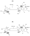
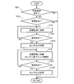
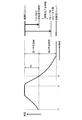
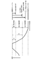
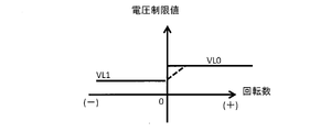
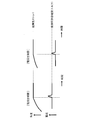
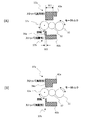
- FIG. 1 is a system diagram of a vehicle internal combustion engine including a variable compression ratio mechanism according to an embodiment of the present invention. It is a figure which shows the stopper structure of the variable compression ratio mechanism in embodiment of this invention. It is a flowchart which shows the flow of stopper position learning in embodiment of this invention. It is a time chart which shows an example of the angle change in the stopper position learning state in the embodiment of the present invention, and a learning period (limit value change timing). It is a figure which illustrates the current limiting value applied in the 1st and 2nd learning period in the embodiment of the present invention. It is a time chart which illustrates the change of the angle in the stopper position learning state in the embodiment of the present invention, number of rotations, and motor current.
- FIG. 1 shows a system configuration of a vehicle internal combustion engine 1 including a variable compression ratio mechanism as an example of a vehicle drive mechanism to which a control device and a control method according to the present invention are applied.
- the internal combustion engine 1 of FIG. 1 is a four-cycle spark ignition engine provided with a variable compression ratio mechanism 2 using a multi-link type piston crank mechanism.
- a pair of intake valves 4 and a pair of exhaust valves 5 are arranged on the ceiling wall surface of the combustion chamber 3 of the internal combustion engine 1, and an ignition plug 6 is provided at the center surrounded by the intake valves 4 and the exhaust valves 5. Is arranged.
- the intake valve 4 opens and closes the intake port 7, and the exhaust valve 5 opens and closes the exhaust port 11.
- a cylinder injection fuel injection valve 8 that directly injects fuel into the combustion chamber 3 is disposed below the intake port 7.
- the intake port 7 is provided with a port injection fuel injection valve 41 that injects fuel into the intake port 7.
- in-cylinder injection fuel injection valve 8 and port injection fuel injection valve 41 are both electromagnetic or piezoelectric injection valves that are opened when a drive pulse signal is applied. An amount of fuel that is substantially proportional to the pulse width is injected.
- the internal combustion engine 1 can include either one of the port injection fuel injection valve 41 and the in-cylinder injection fuel injection valve 8.
- the engine control unit 9 including a microcomputer includes an air flow sensor 10 that detects the intake air flow rate of the internal combustion engine 1, and an air / fuel ratio that detects the air / fuel ratio of the air / fuel mixture based on the oxygen concentration in the exhaust gas of the internal combustion engine 1.
- Sensor 14 a crank angle sensor 15 for detecting the rotation angle of the crankshaft 21, a water temperature sensor 16 for detecting the temperature of the cooling water of the internal combustion engine 1, and an accelerator opening sensor for detecting the amount of depression of the accelerator pedal operated by the driver Detection signals of various sensors such as 17 are input.
- the engine control unit 9 controls the fuel injection amount and injection timing by the fuel injection valves 8 and 41, the ignition timing by the spark plug 6 and the like based on the input detection signal.
- variable compression ratio mechanism 2 as an example of a vehicle drive mechanism uses a known multi-link type piston crank mechanism.
- the variable compression ratio mechanism 2 includes a lower link 22 rotatably supported by a crank pin 21a of the crankshaft 21, an upper link 25 that connects an upper pin 23 at one end of the lower link 22 and a piston pin 24a of a piston 24 to each other.
- a control link 27 having one end connected to a control pin 26 at the other end of the lower link 22, and a control shaft (first control shaft, first moving body) that supports the other end of the control link 27 in a swingable manner. 28 as a main component.
- the crankshaft 21 and the control shaft 28 are rotatably supported by a bearing structure not shown in the crankcase below the cylinder block 29.
- the control shaft 28 has an eccentric shaft portion 28a whose position changes with the rotation of the control shaft 28, and an end portion of the control link 27 is rotatably fitted to the eccentric shaft portion 28a.
- the top dead center position of the piston 24 is displaced vertically as the control shaft 28 rotates, and the mechanical compression ratio of the internal combustion engine 1 changes.
- an electric motor (actuator) 31 having a rotation center axis parallel to the crankshaft 21 is disposed below the cylinder block 29 and is serially connected to the electric motor 31 in the axial direction.
- Reducers 32 are connected so as to line up.
- An output shaft (second control shaft, second moving body) 32 a of the speed reducer 32 is positioned coaxially with an output shaft (not shown) of the electric motor 31.
- the output shaft 32a and the control shaft 28 are positioned in parallel with each other, and the first arm 33 fixed to the output shaft 32a and the first arm fixed to the control shaft 28 are so rotated that they are interlocked with each other.
- Two arms 34 are connected to each other by an intermediate link 35. That is, when the electric motor 31 rotates, the speed is reduced by the speed reducer 32 and the angle of the output shaft 32a changes.
- the rotation of the output shaft 32a of the speed reducer 32 is transmitted from the first arm 33 to the second arm 34 via the intermediate link 35, the control shaft 28 rotates, and the angle of the control shaft 28 changes.
- the top dead center position of the piston 24 is displaced vertically, and the mechanical compression ratio of the internal combustion engine 1 changes.
- the first arm 33 and the second arm 34 extend in the same direction.
- the control is performed when the output shaft 32a of the speed reducer 32 rotates in the clockwise direction.
- the shaft 28 is also configured to rotate in the clockwise direction, but it is also possible to configure the link mechanism so that the output shaft 32a and the control shaft 28 rotate in opposite directions.
- the engine control unit 9 calculates a target compression ratio of the variable compression ratio mechanism 2 based on engine operating conditions (for example, engine load and engine speed), and drives the electric motor 31 based on the target compression ratio and the actual compression ratio. Control. Note that the control unit is separate from the engine control unit 9 and configured to be able to communicate with the engine control unit 9 via CAN or the like to drive and control the electric motor 31 of the variable compression ratio mechanism 2. be able to.
- the engine control unit 9 calculates the target angular position of the control shaft 28 (or output shaft 32a) as the target compression ratio of the variable compression ratio mechanism 2, and detects the angular position of the control shaft 28 (or output shaft 32a).
- the operation amount of the electric motor 31 is calculated so that the actual angular position obtained from the output signal of the angle sensor 36 approaches the target angle position, and energization to the electric motor 31 is controlled based on the calculated operation amount.
- variable compression ratio mechanism 2 includes two stoppers 37a and 37b that define both ends of a rotatable angle region of the control shaft 28 (and the output shaft 32a), and control in which one of the stoppers 37a and 37b abuts.
- the compression ratio becomes maximum at the angular position of the shaft 28 (and the output shaft 32a), and the compression ratio becomes minimum at the angular position of the control shaft 28 (and the output shaft 32a) with which the other abuts.
- the stoppers 37a and 37b are provided in, for example, protrusions (movable parts) 38a and 38b protruding from the outer periphery of the control shaft 28 and / or the output shaft 32a, the cylinder block 29, etc.
- Engaging portions (fixed portions) 39a and 39b, and the protrusions 38a and 38b rotate around the axis so as to be separated from and engaged with the engaging portions 39a and 39b.
- the rotation (movement) of the control shaft 28 (and the output shaft 32a) is restricted by hitting the joint portions 39a and 39b.
- FIGS. 2A and 2B show an example of the structure of the stoppers 37a and 37b.
- one of the stoppers 37 a and 37 b is provided on the output shaft 32 a and the other stopper 37 b is provided on the control shaft 28.
- the protrusion 38a of the stopper 37a is provided integrally with the output shaft 32a, and the engaging part 39a rotates the protrusion 38a clockwise in FIG. Thus, it is arranged in the vicinity of the output shaft 32a so as to abut near the 12 o'clock position.
- FIG. 2A shows a state in which the protrusion 38b of the stopper 37b is in contact with the engaging portion 39b, and the control shaft 28 and the output shaft 32a are further rotated counterclockwise from this state. Cannot be turned, and clockwise rotation is allowed.
- An angular region of approximately 180 deg between the angular position where the stopper 37a abuts and the angular position where the stopper 37b abuts is the rotatable angular region of the control shaft 28 and the output shaft 32a.
- the maximum compression ratio and the minimum compression ratio of the compression ratio are defined by the angular position where the stopper 37a abuts and the angular position where the stopper 37b abuts, and the compression ratio and the stopper 37b at the angular position where the stopper 37a abuts.
- the compression ratio variable region is between the compression ratio at the angular position where the two come into contact.
- the size of the movable angle region of the control shaft 28 is approximately 180 degrees, but it is obvious that the size of the movable angle region is not limited to 180 degrees.
- the engine control unit 9 detects the output of the angle sensor 36 at the angular position where the stopper 37a abuts and the output of the angle sensor 36 at the angular position where the stopper 37b abuts, and stores them as reference output values. Perform stopper position learning. That is, the engine control unit 9 is provided with a function as a learning unit that performs stopper position learning in software.
- the engine control unit 9 detects the angle of the control shaft 28 (output shaft 32a) from the output of the angle sensor 36 and the reference output value, and the operation amount of the electric motor 31 of the variable compression ratio mechanism 2 based on the detected angle value. Is calculated and output.
- FIG. 3 shows the flow of the stopper position learning process by the engine control unit 9.
- step S101 the engine control unit 9 determines whether or not the operating state of the internal combustion engine 1 satisfies the learning execution condition. If the learning execution condition is satisfied, the process proceeds to step S102.
- the steady state operation of the internal combustion engine 1 in a predetermined operation region can be set as the learning execution condition.
- step S102 the engine control unit 9 determines whether or not the stopper position learning is the first time.
- the first stopper position learning means that after the angle sensor 36 is assembled, there is no history of stopper position learning for both the stoppers 37a and 37b, and the reference output value is indefinite. For example, inspection adjustment at a vehicle assembly factory This is the case immediately after learning in the process or exchanging the angle sensor 36 at a maintenance shop. However, it is not limited to the configuration that proceeds to step S103 and subsequent steps at the first learning, and the determination process in step S102 can be omitted. Further, it is possible to provide a means for outputting an initial learning command to the engine control unit 9 when adjustment or replacement work of sensors or actuators is performed in a maintenance shop or the like.
- step S103 the engine control unit 9 proceeds to step S103, and rotates the control shaft 28 and the output shaft 32a in the rotational direction in which one of the stoppers stored as the stopper that performs the learning first comes into contact.
- the electric motor 31 is controlled so as to be moved.
- the engine control unit 9 sets, for example, an angular position that exceeds an angular position at which rotation is restricted by the stopper to be learned as a target angular position, and the electric motor 31 is determined from the output of the angle sensor 36 and the target angular position. Or the rotational speed of the electric motor 31 is controlled to the target rotational speed for learning, and the electric motor 31 is driven in the rotational direction in which the stopper to be learned comes into contact.
- the higher rigidity side (the higher impact resistance side) of the two stoppers 37a and 37b that define both ends of the movable angle region of the control shaft 28 is selected in advance. .
- the stopper 37b is compared with the stopper 37a. Since there are more parts from the electric motor 31 to the stopper 37b than the parts from the electric motor 31 to the stopper 37a, the rigidity of the stopper 37b is lower than the rigidity of the stopper 37a.
- a stopper 37a having a relatively high rigidity is selected as a stopper to be first learned.
- the stopper 37a on the higher rigidity side has higher impact resistance than the stopper 37b on the lower rigidity side, and can be brought into contact at a higher speed, from the initial position (the angular position of the control shaft 28 at the start of learning).
- the control shaft 28 can be rotated in a shorter time to the stopper contact position, and the learning time can be shortened.
- step S103 the engine control unit 9 causes the electric motor 31 to rotate the control shaft 28 at a speed as high as possible that generates an impact force that can be withstood by the stopper 37a having relatively high rigidity.
- Control For example, when learning the stopper 37b having relatively low rigidity, the impact resistance at the time of contact is lower than that of the stopper 37a by the amount of rigidity, and the control shaft 28 is rotated toward the contact position. It is necessary to make the speed (torque) slower (smaller) than when learning the stopper 37a. For this reason, the time required to rotate to the stopper contact position becomes longer, and the learning time becomes longer.
- the variation range of the position where the stopper comes into contact is wide, and control for shock reduction such as weakening the motor torque just before the contact is made accurately. Since it is difficult to perform, it is difficult to learn the stopper 37b having low rigidity in a short time while sufficiently suppressing the impact force of contact. Therefore, the engine control unit 9 is allowed to contact at a higher rotational speed (higher torque) among the stoppers 37a and 37b. The first stopper position learning is performed for the stopper 37a that can shorten the time until it is made.
- the engine control unit 9 determines whether or not the stopper 37a is stably in the contact state by determining whether or not the output of the angle sensor 36 has been maintained at a substantially constant value in step S104. To do.
- the engine control unit 9 determines that the output of the angle sensor 36 is in a stable state when a state where the output of the angle sensor 36 is substantially equal to the previous value continues for a predetermined time or more. If the output of the angle sensor 36 has fluctuated, the engine control unit 9 returns to step S103 and continues the drive control for bringing the stopper 37a into contact, and the output of the angle sensor 36 has a substantially constant value. If it comes to hold
- step S105 the engine control unit 9 stores the output value of the angle sensor 36 at that time as a sensor output at the contact position of the stopper 37a (upper limit value or lower limit value of the compression ratio).
- step S106 reverses the rotational drive direction of the control shaft 28, and rotates the control shaft 28 from the contact position of the stopper 37a toward the contact position of the stopper 37b. 31 is controlled.
- the stopper 37b is a stopper having a lower rigidity than the stopper 37a
- the engine control unit 9 performs buffering control that weakens the impact force when the stopper 37b abuts compared to when the stopper 37a abuts.
- the stopper 37a starts to move from the contact position and is limited to a torque such that the contact impact force is within the allowable range, the time required to rotate the stopper 37b to the contact position becomes long.
- the engine control unit 9 can predict how much the output of the angle sensor 36 will come into contact with the stopper 37b. it can.
- the engine control unit 9 determines the operation amount of the electric motor 31 at the timing during the change in angle detected based on the change in the rotation angle from the contact position of the stopper 37a (change in the output value of the angle sensor 36).
- the buffer control is performed to limit the impact to a smaller value and weaken the impact force when the stopper 37b comes into contact while moving to the contact position of the stopper 37b with good response.
- the engine control unit 9 is estimated that the stopper 37b will not contact in a predetermined angle range immediately after the stopper 37a starts to move, so that the control shaft 28 is allowed to be in contact with the stopper 37b.
- the learning time (movement time) is shortened by rotationally driving at a torque higher than the maximum torque (speed faster than the allowable maximum speed).
- the engine control unit 9 detects that the angle range in which the stopper 37b is likely to come into contact is detected based on the change in the rotation angle from the contact position of the stopper 37a, and the tolerance at the time of contact of the stopper 37b.
- the operation amount of the electric motor 31 is limited to be smaller than before so that the motor torque is less than the maximum torque (the rotation speed is less than the maximum allowable speed).
- the engine control unit 9 performs the above-described buffering control, while shortening the time required to rotate from the contact position of the stopper 37a to the contact position of the stopper 37b (learning time for the stopper 37b).
- the stopper 37b is prevented from being bent or deformed by an impact force at the time of contact.
- step S107 in a state where the control shaft 28 is rotationally driven toward the contact position of the stopper 37b, and whether or not the output of the angle sensor 36 is maintained at a substantially constant value.
- the engine control unit 9 determines whether or not the stopper 37b is stable in the contact state, it is detected in the same manner as in step S104. Until the output of the angle sensor 36 maintains a substantially constant value, the engine control unit 9 returns to step S106 and continues the drive control of the electric motor 31 for contacting the stopper 37b.
- the engine control unit 9 proceeds to step S108, and the output value of the angle sensor 36 at that time is The sensor output is stored at the contact position of the stopper 37b.
- the engine control unit 9 The correlation between the output and the angular position (actual compression ratio) of the control shaft 28 is calibrated based on the learning value, and the electric motor 31 is controlled based on the output of the angle sensor 36.
- the time chart of FIG. 4 is a diagram for explaining an example of buffer control for changing the limit value (upper limit value) CL of the current command value of the electric motor 31.
- the engine control unit 9 sets the current limit value CL as the current command value when the current command value of the electric motor 31 exceeds the current limit value CL, so that the current command value does not exceed the current limit value CL. Like that.
- the engine control unit 9 passes through the stable contact state of the stopper 37a at time t1 from the learning start time at time t0, and the rotation angle of the control shaft 28 from the contact position of the stopper 37a is a predetermined angle.
- the current limit value CL having the characteristics shown in FIG. 5A is used as the current limit value CL.
- the second learning period (movement) from the time t2 when the rotation angle (angle change amount) ⁇ of the control shaft 28 from the contact position of the stopper 37a reaches the predetermined angle ⁇ until the stopper position learning for the stopper 37b is completed.
- the engine control unit 9 uses the current limit value having the characteristics shown in FIG. 5B as the current limit value CL.
- the engine control unit 9 detects the rotation angle ⁇ based on the output change amount of the angle sensor 36 from the sensor output value at the contact position of the stopper 37a. That is, the engine control unit 9 detects the switching timing of the current limit value CL based on the output change amount of the angle sensor 36 from the sensor output value (learned value) at the contact position of the stopper 37a. Perform switching.
- the current limit value CL shown in FIG. 5 (B) is lower than the current limit value CL shown in FIG. 5 (A), so that the motor torque in the second learning period is lower than the motor torque in the first learning period.
- the motor torque is limited to be small.
- the control shaft 28 is moved from the initial position until it comes into contact with the stopper 37a having relatively high rigidity and until the rotation angle from the contact position of the stopper 37a reaches a predetermined angle.
- a relatively high motor torque is generated so as to move with good response.
- the motor torque from when the rotation angle from the contact position of the stopper 37a reaches the predetermined angle ⁇ until the stopper 37b comes into contact is within an allowable range when the stopper 37b comes into contact. To be lower than the initial movement start.
- the current limit value CL is assigned according to the rotation speed and rotation direction of the electric motor 31, and in the present application, the rotation direction approaching the contact position of the stopper 37a is represented by a positive rotation speed, and the contact position of the stopper 37b. The rotation direction approaching is expressed by a negative rotation speed.
- the buffer control can be set so as not to limit the current during the first learning period.
- the limit value at a negative rotation speed in FIG. 5A is a current limit value used when the stopper 37a is brought close to the contact position of the stopper 37b, but the movement from the contact position of the stopper 37a starts.
- a limit value CL larger than the limit value CL1 is used, and the current limit value CL1 that can maintain the desired rotation speed is reduced until immediately before the contact position of the stopper 37b thereafter. It is a characteristic to be made. However, if the motor starting torque is not so much compared to the torque at the time of motor rotation due to the small friction, etc., a negative rotation is used so that the limit value CL1 is used even when the stopper 37a starts to move from the contact position.
- the limit value in the speed range can be uniformly set to CL1.
- the limit value CL0 at a positive rotational speed in FIG. 5A is a current limit value used when the stopper 37a is brought into contact with the stopper 37a.
- the stopper 37a has a relatively high rigidity and has a high impact resistance. Since it is high, the drive of the control shaft 28 with a larger torque is permitted as the limit value CL0 higher than the current limit value CL1.
- the current limit value of FIG. 5B used in the second learning period is a limit value used when the low-rigidity stopper 37b is brought into contact. Both are set to values lower than the limit value CL1 in FIG.
- the limit value CL2 at a negative rotational speed in FIG. 5B is applied when the stopper 37b having low rigidity is brought into contact, the limit value CL2 is smaller than the limit value CL1 and is brought into contact with the stopper 37b. It is set to a value that can be controlled below the allowable maximum torque. That is, when approaching the contact position of the stopper 37b from the contact position of the stopper 37a, initially (first learning period), the current limit value CL is set to the limit value CL1, so that the stopper 37b can be contacted with high response. Motor torque that can be approached is generated.
- the current limit value CL is switched from the limit value CL1 to a smaller limit value CL2, and the impact force applied to the stopper 37b at the time of contact is changed. Reduce the motor torque to within the allowable range.
- the limit value CL3 at the positive rotational speed in FIG. 5B rebounds due to the impact that the stopper 37b abuts (rotational change away from the abutting position of the stopper 37b toward the abutting position of the stopper 37a). Therefore, the current limit value CL3 is set to an intermediate value between the limit value CL1 and the limit value CL2 (CL2 ⁇ CL3 ⁇ CL1) so that the motor torque that returns from the rebound can be obtained. .
- the limit value CL gradually increases from CL2 as the rotational speed increases from zero to the plus direction, and holds the limit value CL3 after reaching the limit value CL3. It can be.
- the time chart of FIG. 6 shows the angle of the control shaft 28, the rotation speed (rpm) of the control shaft 28, the motor current, and the motor current when the current limit value CL of FIG. 5B is applied in the second learning period.
- the change of limit value CL is illustrated.
- the current command value is limited by the current limit value CL2 that can be limited to the motor torque at which the impact force at the time of contact is within the allowable range, and the impact force when the stopper 37b contacts is sufficiently relaxed.
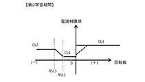
- the current limit value CL when rotating in the minus direction in the second learning period can be uniformly set to the limit value CL2 as shown in FIG. 5B, and as shown in FIG. The limit value can be further lowered in the low rotation speed region in the negative direction.
- the current limit value for the second learning period shown in FIG. 7 is the current limit value between the rotation speed of 0 and the predetermined rotation speed RSL2 among the current limit values in the negative rotation direction toward the stopper 37b.
- the current limit value CL4 (CL4 ⁇ CL2 ⁇ CL3 ⁇ CL1) that is lower than the value CL2 is set, and the current limit value CL is gradually increased as the rotational speed increases between the predetermined rotational speed RSL2 and the predetermined rotational speed RSL3.
- the current limit value CL4 is increased from the current limit value CL2 to a characteristic that holds the current limit value CL2 at a predetermined rotational speed RSL3 or higher.
- the current limit value CL4 applied in the low rotation range in the negative rotation direction is adapted based on the allowable torque when the stopper 37b comes into contact, and can further weaken the impact when the stopper 37b comes into contact. Further, in the characteristic of FIG. 7, the current limit value CL3 (CL2 ⁇ CL3 ⁇ CL1) is applied in the plus side rotational speed region, as in FIG. 5B. Further, when the engine control unit 9 rotates the control shaft 28 from the contact state of the stopper 37a toward the contact position of the stopper 37b, the angle change amount (movement amount) from the contact state of the stopper 37a increases.
- the switching of the current limit value (rotation speed-current limit value table) according to can be performed twice or more.
- the first current limit value (rotational speed-current limit value table) is switched when the angle change amount ⁇ from the contact state of the stopper 37a reaches the first angle ⁇ 1.
- buffer control is shown in which the second current limit value (rotational speed-current limit value table) is switched when the angle change amount ⁇ reaches the second angle ⁇ 2 ( ⁇ 1 ⁇ 2).
- the first learning period starting period in the minus direction
- the current limit of the characteristic shown in FIG. Apply the value CL.
- the current limit value CL11 used at the negative rotational speed in the first learning period is set to a value that can secure a current for starting the motor in the negative direction from the contact state of the stopper 37a, and at the positive rotational speed.
- the current limit value CL10 to be used is set to a value larger than the current limit value CL11. It should be noted that in the positive rotational speed range in the first learning period, it is possible to set so as not to be limited by the current limit value CL.
- the current limit value CL having the characteristics shown in FIG. 9B is applied.
- the second angle ⁇ 2 is set so as to be in an angular range where it is estimated that the stopper 37b does not come into contact in consideration of the variation in the interval angle between the position of the stopper 37a and the position of the stopper 37b.
- the learning time can be shortened by quickly rotating the control shaft 28 in the direction approaching the stopper 37b.
- the current limit value CL12 (CL12 ⁇ CL11) in the minus direction in the second learning period is a value that can maintain the intended rotation speed, that is, a value equivalent to the current limit value CL1 shown in FIG.
- the positive current limit value CL13 in the second learning period is adapted to suppress re-acceleration toward the stopper 37b when the stopper 37b abuts and bounces, so that CL12 ⁇ CL13 ⁇ CL10. Is set.
- the second learning period is an angular region where it is estimated that contact of the stopper 37b does not occur even if the positions of the stoppers 37a and 37b vary as described above, the current limit value CL12 is set to the minus rotation direction. It can be set to be used in both the plus rotation direction.
- the current limit value CL having the characteristics shown in FIG. 9C is applied. Since the third learning period is a period in which the stopper 37b is brought into contact, the current limit value CL14 (CL14 ⁇ CL12) equivalent to the current limit value CL4 shown in FIG. In the positive rotational speed range, a value equivalent to the positive current limit value CL13 in the second learning period is applied.
- the rotational speed-current limit value table is switched twice, and the movement period from the contact state of the stopper 37a to the contact of the stopper 37b is divided into the first half, the middle board, and the second half.
- the motor for rotating the control shaft 28 from the abutting state of the stopper 37a toward the abutting position of the stopper 37b can be activated with good response.
- the control shaft 28 is rotated as fast as possible, and in the latter half of the movement, the torque when the stopper 37b abuts can be sufficiently suppressed to control the abutting impact force within an allowable range.
- the angle change amount ⁇ is the rotation angle of the control shaft 28 from the contact position of the stopper 37a.
- the control accuracy of the rotational speed when the control shaft 28 is rotated toward the contact position of the stopper 37b is improved. be able to.
- the angle change amount ⁇ is in an angle range where the stopper 37b can be contacted, that is, in the second half of the movement which is the second learning period in FIG. 4 or the third learning period in FIG.
- the current control value CL that is set according to the increase of the initial value is set as an initial value, and thereafter the current control value CL is set to a smaller value every time the angle change amount increases by a unit angle (or every elapse of a predetermined unit time). Can do.
- the engine control unit 9 can perform a voltage limiting process for limiting the motor applied voltage to the upper limit value or less together with the current limiting in the second learning period of FIG. 4 or the third learning period of FIG.
- FIG. 10 shows an example of the characteristics of the voltage limit value (voltage upper limit value) VL used for limiting the motor applied voltage in the third learning period of FIG. Note that the characteristics of the voltage limit value (voltage upper limit value) VL in FIG. 10 can also be applied in the second learning period in FIG. In FIG. 10, in the positive rotational speed range, which is a direction approaching the stopper 37a having relatively high rigidity, the applied voltage corresponding to the current values of the current limit values CL3 and CL13 is set to the voltage limit value (applied voltage upper limit value). ) VL0.
- the voltage that becomes the maximum allowable current value (allowable maximum torque) at the time of contact is defined as a voltage limit value VL1 (VL1 ⁇ VL0). To do.
- the motor applied voltage is limited so as not to exceed the voltage limit value VL of the above characteristic, as shown in FIG. 11, the response of the angle change when approaching the stopper contact position becomes slow, but when the stopper contacts It is possible to suppress the motor current from exceeding the current limit value corresponding to the allowable maximum torque.
- the motor applied voltage is limited to a smaller value when the angle change amount reaches a predetermined value without changing the limit value of the motor current (the voltage limit value VL is Change to a smaller value).
- two stoppers having different rigidity are not limited to stoppers respectively provided on two different rotating bodies (the control shaft 28 and the output shaft 32a of the speed reducer 32), and one rotating body has two rigidity.
- the present invention can be applied to a drive mechanism in which different stoppers are provided.
- FIG. 12 shows a projection 38a projecting on the outer periphery of the output shaft 32a of the speed reducer 32, and a first relationship in which the projection 38a abuts around 12:00 when the output shaft 32a rotates in the clockwise direction in FIG.
- One stopper 37a is constituted by the joining portion 40a, and the projection 38a and the second engagement in which the projection 38a abuts around 6 o'clock when the output shaft 32a rotates counterclockwise in FIG.
- the other stopper 37b is constituted by the portion 40b.
- the angle variable region of the output shaft 32a is an angle region between the angular position where the stopper 37a abuts and the angular position where the stopper 37b abuts.
- the wall thickness w1 of the first engagement portion 40a in the rotation direction of the projection portion 38a is thicker than the wall thickness w2 of the second engagement portion 40b in the rotation direction of the projection portion 38a.
- the rigidity of the stopper 37a configured by the combination with the protruding portion 38a is higher than the rigidity of the stopper 37b configured by the combination of the second engaging portion 40b and the protruding portion 38a.
- the rigidity of the stopper 37a is higher than the rigidity of the stopper 37b. Therefore, when the engine control unit 9 performs the stopper position learning, first, the stopper 37a (the first engaging portion 40a and the protrusion) And the output of the angle sensor 36 at the contact position of the stopper 37a is learned.
- the engine control unit 9 rotationally drives the control shaft 28 toward the contact position of the stopper 37b.
- the motor operation unit 9 By switching the limit value in accordance with the change in angle from the contact position of the stopper 37a, the motor operation unit 9 By limiting the amount (current and / or voltage) to a smaller value and suppressing the impact force when the stopper 37b comes into contact with within an allowable range, the contact position of the stopper 37b can be approached with good response.
- the two stoppers 37 a and 37 b are provided on the output shaft 32 a, but the two stoppers 37 a and 37 b can be provided on the control shaft 28.
- the drive mechanism is not limited to the variable compression ratio mechanism 2, for example, a variable valve mechanism that makes the lift characteristics of the intake valve or the exhaust valve of the internal combustion engine variable according to the angle of the control shaft, It is clear that the present invention can be applied.
- the moving body constituting the drive mechanism is not limited to an axis that rotates around the central axis.
- a rack and pinion rack is used as the moving body, and linear movement in the front-rear direction of the rack is limited by a stopper.
- the present invention can be applied to the drive mechanism.
- a control device for controlling a vehicle drive mechanism including an actuator and a sensor for detecting the position of the moving body, comprising a learning unit that learns an output of the sensor in a contact state between the two stoppers.
- the learning unit performs learning for the stopper having the higher rigidity of the two stoppers prior to learning for the stopper having the lower rigidity.
- the learning unit when the learning unit abuts the stopper having a low rigidity, the learning unit increases the output change amount of the sensor from the contact state of the stopper having a high rigidity. Limit the amount of actuator operation to be smaller. In another preferable aspect, the learning unit moves the moving body in a direction approaching the stopper having a lower rigidity than the operation amount when the moving body moves in a direction approaching the stopper having a higher rigidity. The operation amount when moving is limited to be smaller.
- the learning unit responds to an increase in an output change amount of the sensor from a contact state of the stopper having a higher rigidity when the stopper having a lower rigidity is contacted.
- the upper limit value of the manipulated variable is switched to a smaller value.
- the actuator is a motor, and the learning unit limits at least one of the current of the motor and the applied voltage.
- the higher-strength stopper is a stopper closer to the actuator of the two stoppers.
- a control method for controlling a vehicle drive mechanism including an actuator to be driven and a sensor for detecting a position of the moving body, wherein the movement is performed in a direction approaching a stopper having a higher rigidity of the two stoppers. Move the body, learn the output of the sensor while the high-strength stopper is in contact, and move from the contact state of the high-rigidity stopper toward the stopper with low rigidity.
- the amount of operation of the actuator when the body is moved and the moving body is moved in a direction approaching the stopper on the low rigidity side from the contact state of the stopper on the high rigidity side As the amount of change in the output of the sensor from the contact state of the stopper on the side having higher properties increases, the amount of change is limited to a smaller value, and the output of the sensor is learned in the contact state of the stopper on the lower side of rigidity.
- the actuator is controlled based on the learned value.
- SYMBOLS 1 Internal combustion engine, 2 ... Variable compression ratio mechanism (drive mechanism), 9 ... Engine control unit (control apparatus), 28 ... Control shaft (moving body), 31 ... Electric motor (actuator), 32 ... Reduction gear, 36 ... Angle sensor, 37a ... Stopper (high rigidity), 37b ... Stopper (low rigidity)
Landscapes
- Engineering & Computer Science (AREA)
- Chemical & Material Sciences (AREA)
- Mechanical Engineering (AREA)
- General Engineering & Computer Science (AREA)
- Combustion & Propulsion (AREA)
- Analytical Chemistry (AREA)
- Artificial Intelligence (AREA)
- Medical Informatics (AREA)
- Automation & Control Theory (AREA)
- Evolutionary Computation (AREA)
- Health & Medical Sciences (AREA)
- Software Systems (AREA)
- Physics & Mathematics (AREA)
- General Physics & Mathematics (AREA)
- Computer Vision & Pattern Recognition (AREA)
- Output Control And Ontrol Of Special Type Engine (AREA)
- Power Steering Mechanism (AREA)
- Valve Device For Special Equipments (AREA)
- Combined Controls Of Internal Combustion Engines (AREA)
- Control Of Electric Motors In General (AREA)
- Steering Control In Accordance With Driving Conditions (AREA)
Abstract
La présente invention se rapporte à un dispositif et procédé de commande pour commander un mécanisme d'entraînement de véhicule comprenant un corps mobile, dont la plage de mobilité est délimitée par deux butées, ainsi qu'un capteur pour détecter la position du corps mobile. Selon la présente application, le dispositif de commande apprend la sortie provenant du capteur dans un état de contact avec la butée sur le côté plus rigide à l'avant, et réduit de façon croissante la quantité de fonctionnement d'un actionneur lors du déplacement du corps mobile dans la direction vers la butée sur le côté moins rigide à mesure que la quantité de changement dans la sortie provenant du capteur à partir de l'état de contact avec la butée sur le côté plus rigide augmente, et apprend la sortie provenant du capteur dans un état de contact avec la butée sur le côté moins rigide, et commande l'actionneur sur la base des sorties de capteur apprises pour les deux positions de butée.
Priority Applications (6)
| Application Number | Priority Date | Filing Date | Title |
|---|---|---|---|
| EP16759037.1A EP3267014B1 (fr) | 2015-03-05 | 2016-03-04 | Dispositif et procédé de commande de mécanisme d'entraînement de véhicule |
| US15/555,707 US10138806B2 (en) | 2015-03-05 | 2016-03-04 | Control device and control method for vehicle drive mechanism |
| CN201680012895.8A CN107429616B (zh) | 2015-03-05 | 2016-03-04 | 车辆用驱动机构的控制装置以及控制方法 |
| US16/161,635 US10364742B2 (en) | 2015-03-05 | 2018-10-16 | Control device and control method for vehicle drive mechanism |
| US16/433,730 US10738691B2 (en) | 2015-03-05 | 2019-06-06 | Control device and control method for vehicle drive mechanism |
| US16/922,486 US11193417B2 (en) | 2015-03-05 | 2020-07-07 | Control device and control method for vehicle drive mechanism |
Applications Claiming Priority (2)
| Application Number | Priority Date | Filing Date | Title |
|---|---|---|---|
| JP2015-043516 | 2015-03-05 | ||
| JP2015043516A JP6258887B2 (ja) | 2015-03-05 | 2015-03-05 | 車両用駆動機構の制御装置及び制御方法 |
Related Child Applications (2)
| Application Number | Title | Priority Date | Filing Date |
|---|---|---|---|
| US15/555,707 A-371-Of-International US10138806B2 (en) | 2015-03-05 | 2016-03-04 | Control device and control method for vehicle drive mechanism |
| US16/161,635 Continuation US10364742B2 (en) | 2015-03-05 | 2018-10-16 | Control device and control method for vehicle drive mechanism |
Publications (1)
| Publication Number | Publication Date |
|---|---|
| WO2016140345A1 true WO2016140345A1 (fr) | 2016-09-09 |
Family
ID=56847489
Family Applications (1)
| Application Number | Title | Priority Date | Filing Date |
|---|---|---|---|
| PCT/JP2016/056809 Ceased WO2016140345A1 (fr) | 2015-03-05 | 2016-03-04 | Dispositif et procédé de commande de mécanisme d'entraînement de vehicule |
Country Status (5)
| Country | Link |
|---|---|
| US (4) | US10138806B2 (fr) |
| EP (1) | EP3267014B1 (fr) |
| JP (1) | JP6258887B2 (fr) |
| CN (2) | CN110043383B (fr) |
| WO (1) | WO2016140345A1 (fr) |
Cited By (1)
| Publication number | Priority date | Publication date | Assignee | Title |
|---|---|---|---|---|
| WO2017144268A1 (fr) * | 2016-02-26 | 2017-08-31 | Continental Automotive Gmbh | Procédé de fonctionnement et moteur à combustion interne |
Families Citing this family (8)
| Publication number | Priority date | Publication date | Assignee | Title |
|---|---|---|---|---|
| EP3315741B1 (fr) * | 2015-06-25 | 2018-10-24 | Nissan Motor Co., Ltd. | Moteur à combustion interne à taux de compression variable et procédé d'apprentissage pour ce dernier |
| MX364021B (es) * | 2015-07-15 | 2019-04-11 | Nissan Motor | Motor de combustion interna de relacion de compresion variable. |
| JP6492153B2 (ja) * | 2017-12-07 | 2019-03-27 | 日立オートモティブシステムズ株式会社 | 車両用駆動機構の制御装置及び制御方法 |
| JP6979930B2 (ja) * | 2018-06-26 | 2021-12-15 | 日立Astemo株式会社 | 可変圧縮比機構の制御装置 |
| CN110361965B (zh) * | 2019-05-20 | 2022-01-11 | 北京理工大学 | 线性Luenberger观测器的构建方法 |
| EP3748145B1 (fr) * | 2019-06-07 | 2023-12-06 | Winterthur Gas & Diesel Ltd. | Moteur à taux de compression variable (vcr) |
| CN113818970B (zh) * | 2021-08-10 | 2022-12-23 | 浙江吉利控股集团有限公司 | 一种发动机气缸盖、发动机、车辆及沉积物处理方法 |
| CN120729114B (zh) * | 2025-08-19 | 2025-12-23 | 旋智电子科技(上海)有限公司 | 用于预测电机电流的方法、设备、存储介质和程序产品 |
Citations (3)
| Publication number | Priority date | Publication date | Assignee | Title |
|---|---|---|---|---|
| JP2002357135A (ja) * | 2001-05-31 | 2002-12-13 | Nissan Motor Co Ltd | 可変バルブタイミング装置の制御装置 |
| JP2007045394A (ja) * | 2005-07-12 | 2007-02-22 | Nsk Ltd | 電動パワーステアリング装置の制御装置 |
| JP2008215247A (ja) * | 2007-03-06 | 2008-09-18 | Toyota Motor Corp | 内燃機関の可変動弁装置 |
Family Cites Families (15)
| Publication number | Priority date | Publication date | Assignee | Title |
|---|---|---|---|---|
| US5844394A (en) * | 1996-09-20 | 1998-12-01 | Matsushita Electric Industrial Co., Ltd. | Stepping motor controller |
| JP3579398B2 (ja) * | 2002-01-25 | 2004-10-20 | 三菱電機株式会社 | 位置決め制御装置 |
| JP5003723B2 (ja) * | 2002-12-16 | 2012-08-15 | 株式会社デンソー | 電動アクチュエータシステム |
| US7900797B1 (en) | 2004-01-12 | 2011-03-08 | Daryl Dean Witcraft | Lid separator and dispensing device |
| JP5035866B2 (ja) * | 2005-10-04 | 2012-09-26 | ヤンマー株式会社 | 作業車両における動力伝達装置 |
| US7546820B2 (en) * | 2007-10-31 | 2009-06-16 | Ford Global Technologies, Llc | Variable compression ratio engine with lost motion coupling |
| JP2009177965A (ja) * | 2008-01-25 | 2009-08-06 | Denso Corp | モータ制御装置 |
| EP2274521B1 (fr) * | 2008-04-22 | 2020-06-17 | Borgwarner Inc. | Procédé pour commander un actionneur |
| JP5625491B2 (ja) * | 2010-05-17 | 2014-11-19 | いすゞ自動車株式会社 | 流量制御弁の制御装置 |
| JP2012011578A (ja) * | 2010-06-29 | 2012-01-19 | Brother Industries Ltd | カバー開閉機構及び画像処理装置 |
| JP5721256B2 (ja) * | 2011-01-24 | 2015-05-20 | 本田技研工業株式会社 | 電動車両の制御装置 |
| JP5906589B2 (ja) | 2011-06-01 | 2016-04-20 | 日産自動車株式会社 | 内燃機関の故障診断装置 |
| US9243553B2 (en) * | 2013-05-16 | 2016-01-26 | Ford Global Technologies, Llc | Electric waste gate control system sensor calibration with end-stop detection |
| DE102014210930A1 (de) * | 2014-06-06 | 2015-12-17 | Robert Bosch Gmbh | Verfahren und Vorrichtung zum Verstellen eines Stellglieds eines Stellgebersystems mit einem elektronisch kommutierten Stellantrieb |
| MX364021B (es) * | 2015-07-15 | 2019-04-11 | Nissan Motor | Motor de combustion interna de relacion de compresion variable. |
-
2015
- 2015-03-05 JP JP2015043516A patent/JP6258887B2/ja active Active
-
2016
- 2016-03-04 EP EP16759037.1A patent/EP3267014B1/fr active Active
- 2016-03-04 CN CN201910392587.8A patent/CN110043383B/zh active Active
- 2016-03-04 CN CN201680012895.8A patent/CN107429616B/zh active Active
- 2016-03-04 WO PCT/JP2016/056809 patent/WO2016140345A1/fr not_active Ceased
- 2016-03-04 US US15/555,707 patent/US10138806B2/en active Active
-
2018
- 2018-10-16 US US16/161,635 patent/US10364742B2/en active Active
-
2019
- 2019-06-06 US US16/433,730 patent/US10738691B2/en active Active
-
2020
- 2020-07-07 US US16/922,486 patent/US11193417B2/en active Active
Patent Citations (3)
| Publication number | Priority date | Publication date | Assignee | Title |
|---|---|---|---|---|
| JP2002357135A (ja) * | 2001-05-31 | 2002-12-13 | Nissan Motor Co Ltd | 可変バルブタイミング装置の制御装置 |
| JP2007045394A (ja) * | 2005-07-12 | 2007-02-22 | Nsk Ltd | 電動パワーステアリング装置の制御装置 |
| JP2008215247A (ja) * | 2007-03-06 | 2008-09-18 | Toyota Motor Corp | 内燃機関の可変動弁装置 |
Non-Patent Citations (1)
| Title |
|---|
| See also references of EP3267014A4 * |
Cited By (1)
| Publication number | Priority date | Publication date | Assignee | Title |
|---|---|---|---|---|
| WO2017144268A1 (fr) * | 2016-02-26 | 2017-08-31 | Continental Automotive Gmbh | Procédé de fonctionnement et moteur à combustion interne |
Also Published As
| Publication number | Publication date |
|---|---|
| US20200340395A1 (en) | 2020-10-29 |
| US10738691B2 (en) | 2020-08-11 |
| US10138806B2 (en) | 2018-11-27 |
| US20190085762A1 (en) | 2019-03-21 |
| EP3267014A4 (fr) | 2018-08-22 |
| EP3267014A1 (fr) | 2018-01-10 |
| JP2016163519A (ja) | 2016-09-05 |
| CN107429616B (zh) | 2019-06-07 |
| US11193417B2 (en) | 2021-12-07 |
| US20180058314A1 (en) | 2018-03-01 |
| CN110043383A (zh) | 2019-07-23 |
| JP6258887B2 (ja) | 2018-01-10 |
| US10364742B2 (en) | 2019-07-30 |
| CN107429616A (zh) | 2017-12-01 |
| US20190284994A1 (en) | 2019-09-19 |
| CN110043383B (zh) | 2021-09-03 |
| EP3267014B1 (fr) | 2020-12-16 |
Similar Documents
| Publication | Publication Date | Title |
|---|---|---|
| JP6258887B2 (ja) | 車両用駆動機構の制御装置及び制御方法 | |
| JP6659884B2 (ja) | 車両用駆動機構の制御装置及び制御方法 | |
| JP6372617B2 (ja) | 可変圧縮比内燃機関及びその学習方法 | |
| JP6492153B2 (ja) | 車両用駆動機構の制御装置及び制御方法 | |
| CN100516472C (zh) | 可变气门系统 | |
| JP5900701B2 (ja) | 内燃機関の制御装置および制御方法 | |
| JP6057026B2 (ja) | 可変圧縮比内燃機関の制御装置 | |
| JP6854048B2 (ja) | 車両用駆動機構の制御装置及び制御方法 | |
| JP2020002822A (ja) | 車両用駆動機構の制御装置 | |
| JP4207868B2 (ja) | 直線運動機構及び同機構を用いた内燃機関の可変動弁機構 | |
| JP2004116365A (ja) | 可変動弁系の制御装置 | |
| JP2011226331A (ja) | 内燃機関の可変動弁装置 | |
| JP5051146B2 (ja) | 内燃機関の複リンク式可変圧縮比装置 | |
| JP6756309B2 (ja) | 内燃機関の可変動弁機構の制御装置 | |
| JP4605023B2 (ja) | 内燃機関の可変動弁機構制御装置 | |
| JP2006242090A (ja) | 内燃機関の可変動弁装置 | |
| JP2008196335A (ja) | 可変動弁機構の制御装置 | |
| JP2008215239A (ja) | 内燃機関の可変動弁装置 | |
| JP2006250042A (ja) | 内燃機関の制御装置 | |
| JP2007138783A (ja) | 動作位置推定装置 |
Legal Events
| Date | Code | Title | Description |
|---|---|---|---|
| 121 | Ep: the epo has been informed by wipo that ep was designated in this application |
Ref document number: 16759037 Country of ref document: EP Kind code of ref document: A1 |
|
| WWE | Wipo information: entry into national phase |
Ref document number: 15555707 Country of ref document: US |
|
| NENP | Non-entry into the national phase |
Ref country code: DE |
|
| REEP | Request for entry into the european phase |
Ref document number: 2016759037 Country of ref document: EP |