WO2016147457A1 - 湾曲操作装置及び内視鏡 - Google Patents
湾曲操作装置及び内視鏡 Download PDFInfo
- Publication number
- WO2016147457A1 WO2016147457A1 PCT/JP2015/078766 JP2015078766W WO2016147457A1 WO 2016147457 A1 WO2016147457 A1 WO 2016147457A1 JP 2015078766 W JP2015078766 W JP 2015078766W WO 2016147457 A1 WO2016147457 A1 WO 2016147457A1
- Authority
- WO
- WIPO (PCT)
- Prior art keywords
- bending
- wire
- lever
- relay
- endoscope
- Prior art date
- Legal status (The legal status is an assumption and is not a legal conclusion. Google has not performed a legal analysis and makes no representation as to the accuracy of the status listed.)
- Ceased
Links
Images




Classifications
-
- A—HUMAN NECESSITIES
- A61—MEDICAL OR VETERINARY SCIENCE; HYGIENE
- A61B—DIAGNOSIS; SURGERY; IDENTIFICATION
- A61B1/00—Instruments for performing medical examinations of the interior of cavities or tubes of the body by visual or photographical inspection, e.g. endoscopes; Illuminating arrangements therefor
- A61B1/005—Flexible endoscopes
- A61B1/0051—Flexible endoscopes with controlled bending of insertion part
- A61B1/0052—Constructional details of control elements, e.g. handles
-
- A—HUMAN NECESSITIES
- A61—MEDICAL OR VETERINARY SCIENCE; HYGIENE
- A61B—DIAGNOSIS; SURGERY; IDENTIFICATION
- A61B1/00—Instruments for performing medical examinations of the interior of cavities or tubes of the body by visual or photographical inspection, e.g. endoscopes; Illuminating arrangements therefor
- A61B1/005—Flexible endoscopes
- A61B1/0051—Flexible endoscopes with controlled bending of insertion part
- A61B1/0057—Constructional details of force transmission elements, e.g. control wires
-
- G—PHYSICS
- G02—OPTICS
- G02B—OPTICAL ELEMENTS, SYSTEMS OR APPARATUS
- G02B23/00—Telescopes, e.g. binoculars; Periscopes; Instruments for viewing the inside of hollow bodies; Viewfinders; Optical aiming or sighting devices
- G02B23/24—Instruments or systems for viewing the inside of hollow bodies, e.g. fibrescopes
-
- A—HUMAN NECESSITIES
- A61—MEDICAL OR VETERINARY SCIENCE; HYGIENE
- A61B—DIAGNOSIS; SURGERY; IDENTIFICATION
- A61B1/00—Instruments for performing medical examinations of the interior of cavities or tubes of the body by visual or photographical inspection, e.g. endoscopes; Illuminating arrangements therefor
- A61B1/00064—Constructional details of the endoscope body
- A61B1/00066—Proximal part of endoscope body, e.g. handles
-
- A—HUMAN NECESSITIES
- A61—MEDICAL OR VETERINARY SCIENCE; HYGIENE
- A61B—DIAGNOSIS; SURGERY; IDENTIFICATION
- A61B1/00—Instruments for performing medical examinations of the interior of cavities or tubes of the body by visual or photographical inspection, e.g. endoscopes; Illuminating arrangements therefor
- A61B1/04—Instruments for performing medical examinations of the interior of cavities or tubes of the body by visual or photographical inspection, e.g. endoscopes; Illuminating arrangements therefor combined with photographic or television appliances
Definitions
- the present invention relates to a bending operation device and an endoscope for bending a bending portion in conjunction with a tilting operation to a bending lever.
- endoscopes that can be inserted into a subject are widely used in, for example, the medical field or the industrial field in order to observe a portion inside the subject that is difficult to observe, such as the inside of a living body or the inside of a structure. Has been.
- Such an endoscope insertion portion is provided with a bending portion for improving insertion property and observation property in the subject.
- the bending portion is operated to bend by a bending operation device provided in the operation unit.
- Japanese Patent Application Laid-Open No. 2003-325437 discloses a joystick-type bending operation device as a bending operation device for bending a bending portion of an insertion portion.
- This type of bending operation device has a joystick-type bending lever in which a plurality of arm portions are fixed to a base end portion, and a pulling wire connected to the end portion of each arm portion is tilted to the bending lever. By being pulled or relaxed in conjunction with each other, the bending portion can be bent.
- the joystick-type bending lever is generally limited in a tiltable angle, it is difficult to secure a sufficient pulling amount of the pulling wire as compared with a bending operation knob or the like, and a large bending portion is required. It tends to be difficult to perform a bending operation at a bending angle.
- the present invention has been made in view of the above circumstances, and an object thereof is to provide a bending operation device and an endoscope that can bend a bending portion at a sufficient bending angle without increasing the length of an arm portion. To do.
- a bending operation device includes a bending lever that is supported to be tiltable with respect to an operation unit of an endoscope, and a distal end side that can be displaced in conjunction with the tilting operation of the bending lever provided on the bending lever. And a bending portion provided at the insertion portion of the endoscope.
- the arm portion has a power point that is connected to the distal end side of the arm portion via a relay wire.
- a relay lever having a point of action to which a bending wire for bending the portion is connected at a position farther from the fulcrum than the force point.
- an endoscope according to an aspect of the present invention includes the bending operation device in the operation unit.
- FIG. 1 is a front view showing the appearance of the endoscope
- FIG. 2 is a right side view showing the appearance of the endoscope
- FIG. 3 is a top view showing the appearance of the endoscope.
- FIG. 4 is an explanatory view showing an arrangement relationship between the wire pulling member and the cylinder
- FIG. 5 is a perspective view showing an arrangement relationship between the wire pulling mechanism and the cylinder
- FIG. 6 is a perspective view showing an internal structure of the wire pulling mechanism.
- 7 is an exploded perspective view showing the internal structure of the wire pulling mechanism
- FIG. 8 is a cross-sectional view of the main part of the operation part
- FIG. 9 is a view taken along arrow IX in FIG.
- FIG. 11 is a cross-sectional view showing the tip along the line XI-XI in FIG.
- the endoscope 1 of the present embodiment is a bronchial endoscope.
- the endoscope 1 includes an insertion portion 2 formed in an elongated tubular shape, and an insertion portion 2 of the insertion portion 2.
- An operation unit 3 continuously provided at the proximal end, a universal cord 4 which is an endoscope cable extending from the operation unit 3, an endoscope connector 5 disposed at the distal end of the universal cord 4; It is configured with.
- the insertion portion 2 is constituted by a flexible tubular member in which a distal end portion 6, a bending portion 7, and a flexible tube portion 8 are connected in order from the distal end side.
- a metal tip hard portion 10 is provided in the tip portion 6, and the tip hard portion 10 includes a pair of an image pickup unit 11 including an image pickup device such as a CCD or a CMOS.
- the light guide 12 and the treatment instrument insertion channel 13 are held.
- a cutting edge bending piece 20 having a substantially cylindrical shape is fitted on the proximal end side of the distal end hard portion 10, and an outer periphery of the cutting edge bending piece 20 is covered with a bending rubber 22.
- Wire fixing portions 21 are provided at four locations around the insertion axis O on the inner periphery of the cutting edge bending piece 20. Each wire fixing portion 21 has four pulling wires 23 inserted through the insertion portion 2. Either tip is fixed.
- the imaging unit 11 and the treatment instrument insertion channel 13, which are large members, are provided in the distal end rigid portion 10 and the distalmost bending piece 20. Are arranged side by side (see FIGS. 10 and 11), and the light guides 12 are arranged in spaces formed vertically by these arrangements.
- each wire fixing portion 21 rotates by a predetermined angle around the insertion axis O with respect to the vertical and horizontal positions of the distal end portion 6. It is provided at the moved position. That is, for example, as shown in FIG. 11, the cutting edge bending piece 20 is rotated and moved within the range of 30 to 60 degrees around the insertion axis O with respect to the upper direction of the distal end portion 6, and Each wire fixing portion 21 is provided at a position rotated around the insertion axis O within a range of 30 to 60 degrees to the left and right with respect to the downward direction of the distal end portion 6.
- the bending portion 7 can be actively bent in all directions around the insertion axis O including the up / down / left / right directions (UP-DOWN / RIGHT-LEFT) in response to an operation input from the operator or the like to the operation portion 3. It is configured. That is, in the bending portion 7 of the present embodiment, the plurality of bending pieces 25 alternately have a pivot portion 25a disposed in the vertical direction of the insertion portion 2 and a pivot portion 25b disposed in the left-right direction of the insertion portion 2.
- the bending piece set 24 is connected to each other.
- the signal cable 11a, the light guide 12, and the treatment instrument insertion channel 13 extending from the imaging unit 11 are inserted in the same arrangement as that in the distal end portion 6.
- wire guides through which the pulling wires 23 are respectively inserted at positions where the rotational arrangement around the insertion axis O is substantially the same as that of the wire fixing portions 21 described above. (Not shown) is formed.
- the outer periphery of the bending piece set 24 is covered with a bending rubber 22 extending from the distal end portion 6 side.
- the flexible tube portion 8 is formed of a flexible tubular member that can bend passively. Inside the flexible tube portion 8, the signal cable 11a, the light guide 12, and the treatment instrument insertion channel 13 are inserted (all are not shown here).
- the operation unit 3 includes a folding stop 30 connected to the flexible tube 8 in a state where the proximal end of the flexible tube 8 is covered, and a hand of a user or the like connected to the folding stop 30.
- the grip portion 31 is configured to include a grip portion 31 that can be gripped, and an operation portion main body 32 that is connected to the base end side of the grip portion 31.
- the direction around the insertion axis O in the operation unit 3 is defined with reference to a state in which the user or the like grips the grip unit 31.
- the front-rear and left-right directions front surface, back surface, left and right side surfaces, etc. are defined with reference to the user or the like holding the part 31.
- the grip portion 31 is formed in a symmetrical shape with respect to the insertion axis O (center axis), and can be gripped by the user or the like in the same manner with either the left hand or the right hand. It has become.
- a treatment instrument insertion portion 35 is provided on the front surface on the distal end side of the grip portion 31.
- the treatment instrument insertion portion 35 includes a treatment instrument insertion port 35a for inserting treatment instruments (not shown) at various places. Inside the operation section 3, the treatment instrument insertion channel 35 is communicated with the treatment instrument insertion port 35a via a branch member (not shown).
- a forceps plug (not shown), which is a lid member for closing the treatment tool insertion port 35a, is detachable from the treatment tool insertion portion 35.
- the operation unit main body 32 is configured by a hollow member having a substantially partial spherical shape that mainly bulges to the left and right sides and the front side on the proximal end side of the grip unit 31.
- an operation button group 40 for executing various functions of the endoscope 1 is disposed on the front side of the operation unit main body 32.
- a bending lever 45 as an operation lever for performing a bending operation on the bending portion 7 is disposed on the back side of the operation portion main body 32.
- the universal cord 4 extends from one side (for example, the left side) of the operation unit main body 32.
- the left and right shape of the operation portion main body 32 is a shape that is swelled symmetrically with respect to the insertion axis O, and the grip portion 31 is held on the left and right side surfaces on the distal end side of the operation portion main body 32.
- Guide recesses 32a for guiding the user's index finger or the like to the operation button group 40 are formed.
- the universal cord 4 reaches the operation unit 3 from the distal end 6 side through the inside of the insertion unit 2, and further passes various signal lines and the like extending from the operation unit 3 to the inside, and a light guide of a light source device (not shown).
- 12 is a composite cable through which a tube for air / water supply extending from an air / water supply device (not shown) is inserted.
- the endoscope connector 5 has an electric connector portion 5a to which a signal cable for connection with a video processor (not shown) of an external device is connected on a side surface portion, and is connected to a light source device that is an external device.
- the operation button group 40 includes, for example, a suction button 41 a that protrudes from a suction valve 41 that is detachably attached to the operation unit main body 32, and an arbitrary function among various functions related to the endoscope 1. And two button switches 42 to which can be assigned.
- the suction button 41a and the button switch 42 are arranged so as to be symmetrical on the front side of the operation unit main body 32.
- the suction button 41 a is disposed at the center in the left-right width direction of the operation unit main body 32 so as to overlap the insertion axis O.
- the two button switches 42 are arranged at positions that are symmetrical with respect to the insertion axis O on the tip side of the suction button 41a.
- a cylinder 43 connected to the suction valve 41 is provided inside the operation unit main body 32.
- the cylinder 43 is detachably mountable with the suction valve 41, and is disposed at the center in the left-right width direction of the operation unit main body 32 so as to overlap the insertion shaft O corresponding to the arrangement of the suction button 41a. Yes.
- the bending lever 45 is constituted by, for example, a joystick-type lever that can tilt in all directions including up, down, left, and right directions.
- the bending lever 45 is disposed at a position that is symmetrical on the back side of the operation unit main body 32. That is, in the present embodiment, the bending lever 45 is disposed at the center in the left-right width direction of the operation unit main body 32 so as to overlap the insertion axis O.
- the tilting direction of the bending lever 45 is defined as the left-right direction of the tilting operation in the left-right width direction of the operation unit 3, which is a direction orthogonal to the insertion axis O, for example.
- the vertical direction is defined in a direction orthogonal to the horizontal width direction.
- the tilting direction of the bending lever 45 of the present embodiment is, for example, the tilting direction (left tilting direction) for curving the bending portion 7 leftward on the left side in FIG.
- the right side is a tilt direction (right tilt direction) for curving the curved portion 7 to the right side
- the lower side in FIG. 3 is the tilt direction (upward tilt direction) for curving the curved portion 7 upward
- the upper side is defined as a tilt direction (down tilt direction) for bending the bending portion 7 downward.
- a finger rest 46 capable of abutting the thumb of a user or the like is provided at the protruding end of the bending lever 45.
- a wire pulling mechanism 50 is connected to the proximal end side of the bending lever 45 inside the operation unit 3, and the wire pulling mechanism 50 is further connected via a relay lever mechanism 60.
- Each pulling wire 23 is connected.
- the bending lever 45 and the wire pulling mechanism 50 and the relay lever mechanism 60 constitute a bending operation device 70 for bending the bending portion 7 in an arbitrary direction.
- the wire pulling mechanism 50 includes a housing 51, a rotating frame 52 that is rotatably supported in the housing 51, and a rotating frame 52 that rotates in the rotating frame 52.
- the base member 53 is pivotally supported so as to be freely movable (oscillated), and the wire pulling member 54 is fixed to the base member 53.
- the housing 51 is constituted by a substantially cylindrical member, and axial holes 51 a facing each other are formed in the peripheral wall of the housing 51.
- the rotation frame 52 is constituted by a frame body having a substantially rectangular shape, for example.
- the rotating frame 52 has a pair of screw holes 52a facing each other in the center of both ends in the longitudinal direction, and a pair of shaft holes 52b facing each other in the center of both ends in the short direction. ing. Then, the screw 55 inserted into each shaft hole 51 a of the housing 51 is screwed into each screw hole 52 a, so that the rotation frame 52 is pivotally supported with respect to the housing 51.
- the base member 53 is configured by a substantially cylindrical member.
- a bending lever 45 is integrally formed on the central axis of the base member 53.
- a pair of flat portions 53b facing each other are formed in the peripheral portion of the base member 53, and a screw hole 53c penetrating the flat portions 53b is formed. Screws 53 inserted into the respective shaft holes 52b of the rotating frame 52 are screwed into the screw holes 53c, whereby the base member 53 is pivotally supported with respect to the rotating frame 52. Yes.
- the base member 53 is supported by the housing 51 via the rotation frame 52, so that the bending lever 45 integrally connected to the base member 53 tilts in an arbitrary direction. Is possible.
- the wire pulling member 54 is configured by a plate-like member in which the arm portion 54b extends in four different directions. More specifically, in the present embodiment, the wire pulling member 54 is configured by a cross-shaped plate member in which the angle formed by the adjacent arm portions 54b is set to 90 degrees, and the central portion 54a thereof is a screw 57. It is being fixed to the base member 53 via. In other words, the bending lever 45 is connected to the wire pulling member 54 via the base member 53, whereby the distal end side of each arm portion 54 b can be displaced in conjunction with the tilting operation of the bending lever 45. In addition, a wire fixing hole 54c is formed on the distal end side of each arm portion 54b supported in such a manner as to be displaceable.
- the angle formed by each arm portion 54b is not limited to 90 degrees, and can be arbitrarily changed within a range of ⁇ 30 degrees with reference to the 90 degrees.
- the wire pulling mechanism 50 configured as described above is disposed in the operation portion main body 32 so as to face the cylinder 43 in the front-rear direction.
- each arm portion 54b is within a range of 30 to 60 degrees around the central axis Ol of the bending lever 45 with respect to the vertical and horizontal tilt directions defined by the bending lever 45. It is arranged at a position where it is rotated (for example, a position that is rotated 45 degrees).
- the wire pulling mechanism 50 is disposed in a state where the cylinder 43 faces the two arm portions 54 b of the wire pulling member 54.
- the relay lever mechanism 60 includes a pair of left and right stays 61 extending from the operation unit main body 32 into the gripping part 33, and four relay levers supported by these stays 61. 62.
- the relay levers 62 are arranged side by side in the left and right sides in the gripping portion 33, and the fixed end sides of the relay levers 62 are supported so as to be swingable around a single shaft portion 63 installed between the left and right stays 61. Has been.
- relay levers 62 correspond to the arm portions 54 b of the wire pulling mechanism 50, and in the middle of each relay lever 62, the displacement amount of each arm portion 54 b accompanying the tilting operation of the bending lever 45 is the relay wire 65.
- the force point 62a transmitted through the is set. Further, on the free end side of each relay lever 62 located farther from the fulcrum (shaft portion 63) than the force point 62a, an action for amplifying the amount of displacement of each arm portion 54b and transmitting it to each traction wire 23. A point 62b is set.
- the proximal end side of the relay wire 65 is connected to the wire fixing hole 54c of each arm portion 54b.
- the force point 62 a of each relay lever 62 is provided with a screw-type first wire adjusting unit 66 for adjusting the length of the relay wire 65, and the relay is provided via the first wire adjusting unit 66.
- the tip end side of the wire 65 is connected.
- a pulley 68 supported by the operation section main body 32 is engaged in the middle of each relay wire 65.
- each relay wire 65 has an angle (within a predetermined angle range with respect to the vertical direction of the arm portion 54b when the bending lever 45 is in a neutral state, depending on the setting position of each pulley 68, etc. For example, it is adjusted so as to be directed at an angle within an error range of about ⁇ 20 ° with respect to the vertical direction of the arm portion 54b.
- each relay wire 65 has an angle within a predetermined angle range with respect to the vertical direction of the relay lever 62 when the bending lever 45 is in a neutral state (for example, due to the setting position of each pulley 68, for example)
- the angle is within an error range of about ⁇ 20 ° with respect to the vertical direction of the relay lever 62.
- a screw-type second wire adjusting portion 67 for adjusting the length of the pulling wire 23 is provided at the action point 62 b of each relay lever 62.
- the proximal end side of the pulling wire 23 is connected via the second wire adjusting portion 67.
- the front end side of each pulling wire 23 is routed in the insertion portion 2 in a state where the top, bottom, left and right are crossed.
- the two arm portions 54b positioned mainly in the left tilt direction are used.
- the relay wire 65 connected to is pulled.
- the pulling to these relay wires 65 is transmitted to the corresponding relay levers 62, and each relay lever 62 is swung at an angle corresponding to the pulling amount. Accordingly, in the bending portion 7, the two pulling wires 23 positioned mainly on the right side in the bending direction are pulled by the pulling amount amplified by the relay lever 62, and the bending portion 7 is bent to the right side.
- the two arm portions 54b positioned mainly in the downward tilt direction.
- the relay wire 65 connected to is pulled.
- the pulling to these relay wires 65 is transmitted to the corresponding relay levers 62, and each relay lever 62 is swung at an angle corresponding to the pulling amount.
- the two pulling wires 23 positioned mainly on the lower side in the bending direction are pulled by the pulling amount amplified by the relay lever 62, and the bending portion 7 is bent upward.
- the two arm portions 54b positioned mainly in the upward tilt direction.
- the relay wire 65 connected to is pulled.
- the pulling to these relay wires 65 is transmitted to the corresponding relay levers 62, and each relay lever 62 is swung at an angle corresponding to the pulling amount.
- the two pulling wires 23 positioned mainly on the upper side in the bending direction are pulled by the pulling amount amplified by the relay lever 62, and the bending portion 7 is bent downward.
- the bending lever 45 supported to be tiltable with respect to the operation unit 3 of the endoscope 1, and the tip provided in conjunction with the tilting operation of the bending lever 45 provided on the bending lever 45.
- the arm portion 54b whose side is displaceable, and a force point 62a that is connected to the distal end side of the arm portion 54b via the relay wire 65 are supported in the middle, and the bending wire 23 is connected.
- the relay lever 62 having the action point 62b at a position farther from the fulcrum (shaft portion 63) than the force point 62a, thereby constituting the bending operation device 70, thereby making the bending portion without lengthening the arm portion 54b. 7 can be bent at a sufficient bending angle.
- the amount of displacement (traction amount) by the arm portion 54b is amplified by the relay lever 62 and then transmitted to the pulling wire 23, so that the bending portion 7 can be moved with a sufficient pulling amount without increasing the length of the arm portion 54b. It can be bent. Therefore, interference between the arm portion 54b and other built-in objects can be prevented, and further, the enlargement of the operation portion 3 can be effectively suppressed.
- a pulley 68 that engages in the middle of the relay wire 65 is provided, and the pulley 68 directs the proximal end side of the relay wire 65 when the bending lever 45 is in a neutral state to be substantially perpendicular to the arm portion 54b.
- the pulley 68 is set so that the distal end side of the relay wire 65 when the bending lever 45 is in the neutral state is oriented substantially perpendicular to the relay lever 62, so that the traction amount by the relay wire 65 can be efficiently increased. It can be converted into the swing amount of the relay lever 62.
- the inside of the operation portion 3 is provided. Dead space can be used effectively.
- the relay levers 62 can be arranged in one place.
- the length of the first wire adjusting portion 66 for adjusting the length of the relay wire 65 connected to the force point 62 a of each relay lever 62 and the length of the pulling wire 23 connected to the action point 62 b of each relay lever 62 are set.
- the second wire adjustment portion 67 for adjustment in the relay lever mechanism 60 the relationship between the tilting state of the bending lever 45 and the bending state of the bending portion 7 can be easily tuned. That is, in the relay lever mechanism 60 of the present embodiment having the first and second wire adjusting portions 66 and 67, the tilting state and the bending of the bending lever 45 are adjusted by adjusting the length of the relay wire 65 by the first wire adjusting portion 66.
- the relationship with the curved state of the portion 7 can be roughly adjusted, and then the above relationship can be finely adjusted by adjusting the length of the pulling wire 23 by the second wire adjusting portion 67, and the tuning operation can be simplified.
- the relay levers 62 are collectively arranged in the gripping portion 33, and the first and second wire adjusting portions 66 and 67 are connected to the force point 62a and the action point 62b of each relay lever 62.
Landscapes
- Health & Medical Sciences (AREA)
- Life Sciences & Earth Sciences (AREA)
- Physics & Mathematics (AREA)
- Surgery (AREA)
- Optics & Photonics (AREA)
- Biomedical Technology (AREA)
- Public Health (AREA)
- Nuclear Medicine, Radiotherapy & Molecular Imaging (AREA)
- Pathology (AREA)
- Radiology & Medical Imaging (AREA)
- Veterinary Medicine (AREA)
- Engineering & Computer Science (AREA)
- Molecular Biology (AREA)
- Biophysics (AREA)
- Medical Informatics (AREA)
- Heart & Thoracic Surgery (AREA)
- Animal Behavior & Ethology (AREA)
- General Health & Medical Sciences (AREA)
- General Physics & Mathematics (AREA)
- Astronomy & Astrophysics (AREA)
- Instruments For Viewing The Inside Of Hollow Bodies (AREA)
- Endoscopes (AREA)
Abstract
内視鏡1の操作部3に対して傾動可能に支持された湾曲レバー45と、この湾曲レバー45に設けられ当該湾曲レバー45の傾動動作に連動して先端側が変位可能なアーム部54bと、操作部3に対して揺動可能に支持され、アーム部54bの先端側が中継ワイヤ65を介して接続する力点62cを中途に有するとともに、湾曲ワイヤ23が接続する作用点62bを力点62aよりも支点(軸部63)から離間した位置に有する中継レバー62と、を備えて湾曲操作装置70を構成する。
Description
本発明は、湾曲レバーへの傾動操作に連動して湾曲部を湾曲動作させる湾曲操作装置及び内視鏡に関する。
従来、生体の体内、構造物の内部など、観察が困難な被検体の内部の箇所を観察するために、被検体内に挿入可能な内視鏡が、例えば、医療分野または工業分野において広く利用されている。
このような内視鏡の挿入部には、被検体内の挿入性及び観察性を向上させるための湾曲部が設けられている。この湾曲部は、操作部に設けられた湾曲操作装置により湾曲操作される。
例えば、日本国特開2003-325437号公報には、挿入部の湾曲部を湾曲操作するための湾曲操作装置として、ジョイスティック型の湾曲操作装置が開示されている。この種の湾曲操作装置は、基端部に複数のアーム部が固設されたジョイスティック型の湾曲レバーを有し、各アーム部の端部に連結された牽引ワイヤが湾曲レバーへの傾動動作に連動して牽引或いは弛緩されることにより、湾曲部を湾曲動作させることが可能となっている。
しかしながら、ジョイスティック型の湾曲レバーは、一般に、傾動可能な角度が所定に制限されるため、湾曲操作ノブ等に比べて牽引ワイヤの牽引量を十分に確保することが困難であり、湾曲部を大きな湾曲角度にて湾曲動作させることが困難な傾向にある。
これに対処し、各アーム部を長く設定すると、操作部内においてアーム部と他の内蔵物とが干渉する虞があり、このようなアーム部と内蔵物との干渉を回避しようとすると操作部の大型化等を招く虞がある。
本発明は上記事情に鑑みてなされたもので、アーム部を長大化させることなく、湾曲部を十分な湾曲角度で湾曲動作させることができる湾曲操作装置及び内視鏡を提供することを目的とする。
本発明の一態様による湾曲操作装置は、内視鏡の操作部に対して傾動可能に支持された湾曲レバーと、前記湾曲レバーに設けられ当該湾曲レバーの傾動動作に連動して先端側が変位可能なアーム部と、前記操作部に対して揺動可能に支持され、前記アーム部の先端側が中継ワイヤを介して接続する力点を中途に有するとともに、前記内視鏡の挿入部に設けられた湾曲部を湾曲動作させるための湾曲ワイヤが接続する作用点を前記力点よりも支点から離間した位置に有する中継レバーと、を備えたものである。
また、本発明の一態様による内視鏡は、前記湾曲操作装置を前記操作部に備えたものである。
以下、図面を参照して本発明の形態を説明する。図面は本発明の一実施形態に係り、図1は内視鏡の外観を示す正面図、図2は内視鏡の外観を示す右側面図、図3は内視鏡の外観を示す上面図、図4はワイヤ牽引部材とシリンダとの配置関係を示す説明図、図5はワイヤ牽引機構とシリンダとの配置関係を示す斜視図、図6はワイヤ牽引機構の内部構造体を示す斜視図、図7はワイヤ牽引機構の内部構造体を示す分解斜視図、図8は操作部の要部断面図、図9は図8のIX矢視図、図10は先端部及び湾曲部の要部を示す横断面図、図11は先端部を図10のXI-XI線に沿って示す断面図である。
図1,2に示すように、本実施形態の内視鏡1は気管支用の内視鏡であり、この内視鏡1は、細長管状に形成された挿入部2と、この挿入部2の基端に連設された操作部3と、この操作部3から延設された内視鏡ケーブルであるユニバーサルコード4と、このユニバーサルコード4の先端に配設された内視鏡コネクタ5と、を備えて構成されている。
挿入部2は、先端側から順に、先端部6、湾曲部7、可撓管部8が連設された可撓性を有する管状部材によって構成されている。
例えば、図10,11に示すように、先端部6内には金属製の先端硬質部10が設けられ、この先端硬質部10にはCCD,CMOS等の撮像素子を内蔵した撮像ユニット11、一対のライトガイド12、及び、処置具挿通チャンネル13が保持されている。
また、先端部6内において、先端硬質部10の基端側には、略円筒形状をなす最先端湾曲駒20が外嵌され、この最先端湾曲駒20の外周が湾曲ゴム22によって覆われている。最先端湾曲駒20の内周には、挿入軸O周りの4箇所にワイヤ固定部21が設けられ、各ワイヤ固定部21には、挿入部2内に挿通された4本の牽引ワイヤ23の何れかの先端がそれぞれ固定されている。
ここで、先端部6を太径化させることなく各構成部材を効率良く配置するため、先端硬質部10及び最先端湾曲駒20内には大型部材である撮像ユニット11と処置具挿通チャンネル13とが左右に並んで配置され、(図10,11参照)、これらの配置によって上下に形成されたスペースにライトガイド12がそれぞれ配置されている。
また、撮像ユニット11及び処置具挿通チャンネル13と、各牽引ワイヤ23との干渉を回避するため、各ワイヤ固定部21は、先端部6の上下左右位置に対して挿入軸O周りに所定角度回転移動した位置に設けられている。すなわち、例えば、図11に示すように、最先端湾曲駒20には、先端部6の上方向を基準として挿入軸O周りに左右それぞれ30~60度の範囲内で回転移動させた位置、及び、先端部6の下方向を基準として挿入軸O周りに左右それぞれ30~60度の範囲内で回転移動させた位置に、各ワイヤ固定部21が設けられている。
湾曲部7は、操作部3に対する術者等の操作入力に応じて、上下左右方向(UP-DOWN/RIGHT-LEFT)を含む挿入軸O周りの全方向へと能動的に湾曲させ得るように構成されている。すなわち、本実施形態の湾曲部7は、複数の湾曲駒25が、挿入部2の上下方向に配置された枢軸部25aと、挿入部2の左右方向に配置された枢軸部25bと、を交互に介して連結された湾曲駒組24を有して構成されている。
この湾曲駒組24の内部には、撮像ユニット11から延在する信号ケーブル11a、ライトガイド12、及び、処置具挿通チャンネル13が、先端部6内と略同様の配置にて挿通されている。また、湾曲駒組24を構成する所定の湾曲駒25には、挿入軸O周りの回転配置が上述の各ワイヤ固定部21と略同様となる位置に、各牽引ワイヤ23をそれぞれ挿通するワイヤガイド(図示せず)が形成されている。さらに、湾曲駒組24の外周は、先端部6側から延在する湾曲ゴム22によって覆われている。
可撓管部8は、受動的に湾曲可能な可撓性を有する管状部材によって構成されている。この可撓管部8の内部には、上述の信号ケーブル11a、ライトガイド12、及び、処置具挿通チャンネル13が挿通されている(ここでは、何れも不図示)。
操作部3は、可撓管部8の基端を覆った状態にて当該可撓管部8に接続された折れ止部30と、この折れ止部30に連設され使用者等の手によって把持可能な把持部31と、この把持部31の基端側に連設された操作部本体32と、を有して構成されている。なお、本実施形態において、操作部3における挿入軸O周りの方向等は使用者等が把持部31を把持した状態を基準として定義されており、具体的には、操作部3には、把持部31を把持した使用者等を基準とする前後左右方向(前面、背面、及び、左右側面等)が定義されている。
図1に示すように、把持部31は、挿入軸O(中心軸)に対して左右対称な形状に形成され、使用者等が左手或いは右手の何れの手によっても同様に把持することが可能となっている。
また、把持部31の先端側の前面には、処置具挿通部35が設けられている。この処置具挿通部35は、各所の処置具(不図示)を挿入する処置具挿通口35aを備えて構成されている。操作部3の内部において、処置具挿通口35aには、図示しない分岐部材を介して、処置具挿通チャンネル13が連通されている。また、処置具挿通部35には、処置具挿通口35aを閉塞するための蓋部材である鉗子栓(不図示)が着脱自在となっている。
操作部本体32は、把持部31の基端側において、主として左右側方及び前方に膨出された略部分球状をなす中空部材によって構成されている。この操作部本体32の前面側には、内視鏡1の各種機能を実行するための操作ボタン群40が配設されている。一方、操作部本体32の背面側には、湾曲部7に対する湾曲操作を行うための操作レバーとしての湾曲レバー45が配設されている。さらに、操作部本体32の一側部(例えば、左側部)からは、ユニバーサルコード4が延出されている。
ここで、操作部本体32の左右形状は挿入軸Oに対して左右対称に膨出された形状となっており、この操作部本体32の先端側の左右側面には、把持部31を把持した使用者の人差し指等を操作ボタン群40に導くガイド用凹部32aがそれぞれ形成されている。
ユニバーサルコード4は、挿入部2の内部を通じて先端部6側から操作部3に至り、さらに操作部3から延出する各種信号線などを内部に挿通するとともに、光源装置(不図示)のライトガイド12を挿通し、さらに送気送水装置(不図示)から延出される送気送水用チューブを挿通する複合ケーブルである。
内視鏡コネクタ5は、外部機器のビデオプロセッサ(不図示)との間を接続する信号ケーブルが接続される電気コネクタ部5aを側面部に有するとともに、外部機器である光源装置との間を接続するライトガイド及び電気ケーブルが接続される光源コネクタ部5bと、を有して構成されている。
次に、操作部本体32における各部の構成について、より詳細に説明する。
図1に示すように、操作ボタン群40は、例えば、操作部本体32に着脱自在に装着された吸引バルブ41から突出する吸引ボタン41aと、内視鏡1に関する各種機能の中から任意の機能を割り当てることが可能な2つのボタンスイッチ42と、を有して構成されている。
これら吸引ボタン41a及びボタンスイッチ42は、操作部本体32の前面側において、左右対称となるよう配置されている。すなわち、本実施形態において、吸引ボタン41aは、挿入軸Oに重畳するよう、操作部本体32の左右幅方向の中央に配置されている。また、2つのボタンスイッチ42は、吸引ボタン41aよりも先端側において、挿入軸Oを挟んで左右対称な位置に配置されている。
ここで、例えば図4に示すように、操作部本体32の内部には、吸引バルブ41に連設するシリンダ43が設けられている。このシリンダ43は、吸引バルブ41を着脱自在に装着可能となっており、吸引ボタン41aの配置に対応して挿入軸Oに重畳するよう、操作部本体32の左右幅方向の中央に配置されている。
湾曲レバー45は、例えば、上下左右方向を含む全方向に傾動可能なジョイスティック型のレバーによって構成されている。この湾曲レバー45は、操作部本体32の背面側において、左右対称となる位置に配置されている。すなわち、本実施形態において、湾曲レバー45は、挿入軸Oに重畳するよう、操作部本体32の左右幅方向の中央に配置されている。ここで、例えば、図3に示すように、この湾曲レバー45の傾動方向は、例えば、挿入軸Oに直交する方向である操作部3の左右幅方向に傾動操作の左右方向が定義され、この左右幅方向に直交する方向に上下方向が定義されている。
より具体的には、本実施形態の湾曲レバー45の傾動方向は、例えば、図3中の紙面左側が湾曲部7を左側に湾曲させるための傾動方向(左傾動方向)、図3中の紙面右側が湾曲部7を右側に湾曲させるための傾動方向(右傾動方向)、図3中の紙面下側が湾曲部7を上側に湾曲させるための傾動方向(上傾動方向)、図3中の紙面上側が湾曲部7を下側に湾曲させるための傾動方向(下傾動方向)としてそれぞれ定義されている。
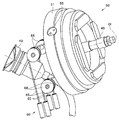
湾曲レバー45の突端部には、使用者等の親指等を当接させることが可能な指当て部46が設けられている。また、図8に示すように、操作部3の内部において、湾曲レバー45の基端側にはワイヤ牽引機構50が連設され、さらに、このワイヤ牽引機構50には、中継レバー機構60を介して各牽引ワイヤ23が接続されている。そして、湾曲レバー45は、これらワイヤ牽引機構50及び中継レバー機構60とともに、湾曲部7を任意の方向に湾曲動作させるための湾曲操作装置70を構成する。
図5~8に示すように、ワイヤ牽引機構50は、ハウジング51と、このハウジング51内に回動(揺動)自在に軸支される回動枠52と、この回動枠52内に回動(揺動)自在に軸支されるベース部材53と、このベース部材53に固設されるワイヤ牽引部材54と、を有して構成されている。
ハウジング51は、略円筒形状をなす部材によって構成され、このハウジング51の周壁には、互いに対向する軸孔51aが穿設されている。
回動枠52は、例えば、略矩形形状をなす枠体によって構成されている。この回動枠52には、長手方向両端部の中央に互いに対向する一対のねじ孔52aが穿設され、さらに、短手方向両端部の中央に互いに対向する一対の軸孔52bが穿設されている。そして、ハウジング51の各軸孔51aにそれぞれ挿通されたビス55が各ねじ孔52aに螺合することにより、回動枠52はハウジング51に対して回動自在に軸支されている。
ベース部材53は、略円柱形状をなす部材によって構成されている。このベース部材53の中心軸上には、湾曲レバー45が一体形成されている。また、ベース部材53の周部には、互いに対向する一対の平坦部53bが形成され、さらに、これら平坦部53bを貫通するねじ孔53cが穿設されている。このねじ孔53cには、回動枠52の各軸孔52bにそれぞれ挿通されたビス56が螺合され、これにより、ベース部材53は回動枠52に対して回動自在に軸支されている。そして、このようにベース部材53が回動枠52を介してハウジング51に支持されることにより、ベース部材53に対して一体に連設された湾曲レバー45は任意の方向に対して傾動することが可能となっている。
ワイヤ牽引部材54は、互いに異なる4方向にアーム部54bが延出された板状の部材によって構成されている。本実施形態において、より具体的には、ワイヤ牽引部材54は、互いに隣接するアーム部54bのなす角度が90度に設定された十字状の板状部材によって構成され、その中心部54aがビス57を介してベース部材53に固定されている。すなわち、ワイヤ牽引部材54にはベース部材53を介して湾曲レバー45が連結され、これにより、各アーム部54bの先端側は、湾曲レバー45の傾動動作に連動して変位可能となっている。また、このように変位可能に支持された各アーム部54bの先端側には、ワイヤ固定孔54cが穿設されている。なお、各アーム部54bのなす角度は90度に限定されるものではなく、例えば、当該90度を基準とする±30度の範囲内において任意に変更することも可能である。
このように構成されたワイヤ牽引機構50は、操作部本体32内において、シリンダ43と前後に対向するよう配置されている。この場合において、ワイヤ牽引機構50は、各アーム部54bが湾曲レバー45に定義された上下左右の傾動方向に対して当該湾曲レバー45の中心軸Ol周りにそれぞれ30度~60度の範囲内で回転移動させた位置(例えば、45度回転移動させた位置)に配置されている。これにより、例えば、図4に示すように、ワイヤ牽引機構50は、ワイヤ牽引部材54の2つのアーム部54bの間にシリンダ43が臨まされた状態にて配置されている。
図8,9に示すように、中継レバー機構60は、操作部本体32内から把持部33内へと延在する左右一対のステー61と、これらのステー61に支持された4本の中継レバー62と、を有して構成されている。
各中継レバー62は、把持部33内において左右一列に並んで配置され、これら中継レバー62の固定端側が、左右のステー61間に架設する単一の軸部63を支点として揺動可能に支持されている。
これら各中継レバー62はワイヤ牽引機構50の各アーム部54bに対応するものであり、各中継レバー62の中途には、湾曲レバー45の傾動動作に伴う各アーム部54bの変位量が中継ワイヤ65を介して伝達される力点62aが設定されている。さらに、力点62aよりも支点(軸部63)から離間した位置にある各中継レバー62の自由端側には、各アーム部54bの変位量を増幅して各牽引ワイヤ23に伝達するための作用点62bが設定されている。
具体的に説明すると、例えば、図8,9に示すように、各アーム部54bのワイヤ固定孔54cには、中継ワイヤ65の基端側が接続されている。一方、各中継レバー62の力点62aには、中継ワイヤ65の長さを調整するためのネジ式の第1のワイヤ調整部66が設けられ、この第1のワイヤ調整部66を介して、中継ワイヤ65の先端側が接続されている。さらに、各中継ワイヤ65の中途には、操作部本体32に支持されたプーリ68が係合されている。
そして、各中継ワイヤ65の基端側は、各プーリ68の配設位置の設定等により、湾曲レバー45が中立状態にあるときのアーム部54bの垂直方向に対して所定角度範囲内の角度(例えば、アーム部54bの垂直方向に対して±20°程度の誤差範囲内の角度)にて指向するよう調整されている。さらに、各中継ワイヤ65の先端側は、各プーリ68の配設位置の設定等により、湾曲レバー45が中立状態にあるときの中継レバー62の垂直方向に対して所定角度範囲内の角度(例えば、中継レバー62の垂直方向に対して±20°程度の誤差範囲内の角度)にて指向するよう調整されている。
また、例えば、図8,9に示すように、各中継レバー62の作用点62bには、牽引ワイヤ23の長さを調整するためのネジ式の第2のワイヤ調整部67が設けられ、この第2のワイヤ調整部67を介して、牽引ワイヤ23の基端側が接続されている。なお、各牽引ワイヤ23の先端側は、上下左右がそれぞれクロスした状態にて挿入部2内に配索されている。
このような構成において、例えば、使用者等が操作部3の把持部31を把持し、把持した手の親指によって湾曲レバー45を左傾動方向に傾動させると、主として、右傾動方向に位置する2つのアーム部54bに連結された中継ワイヤ65が牽引される。これらの中継ワイヤ65への牽引は、対応する各中継レバー62に伝達され、各中継レバー62は牽引量に応じた角度にて揺動される。これにより、湾曲部7内においては、主として湾曲方向左側に位置する2本の牽引ワイヤ23が中継レバー62によって増幅された牽引量にて牽引され、湾曲部7は左側に湾曲される。
また、例えば、使用者等が操作部3の把持部31を把持し、把持した手の親指によって湾曲レバー45を右傾動方向に傾動させると、主として、左傾動方向に位置する2つのアーム部54bに連結された中継ワイヤ65が牽引される。これらの中継ワイヤ65への牽引は、対応する各中継レバー62に伝達され、各中継レバー62は牽引量に応じた角度にて揺動される。これにより、湾曲部7内においては、主として湾曲方向右側に位置する2本の牽引ワイヤ23が中継レバー62によって増幅された牽引量にて牽引され、湾曲部7は右側に湾曲される。
また、例えば、使用者等が操作部3の把持部31を把持し、把持した手の親指によって湾曲レバー45を上傾動方向に傾動させると、主として、下傾動方向に位置する2つのアーム部54bに連結された中継ワイヤ65が牽引される。これらの中継ワイヤ65への牽引は、対応する各中継レバー62に伝達され、各中継レバー62は牽引量に応じた角度にて揺動される。これにより、湾曲部7内においては、主として湾曲方向下側に位置する2本の牽引ワイヤ23が中継レバー62によって増幅された牽引量にて牽引され、湾曲部7は上側に湾曲される。
また、例えば、使用者等が操作部3の把持部31を把持し、把持した手の親指によって湾曲レバー45を下傾動方向に傾動させると、主として、上傾動方向に位置する2つのアーム部54bに連結された中継ワイヤ65が牽引される。これらの中継ワイヤ65への牽引は、対応する各中継レバー62に伝達され、各中継レバー62は牽引量に応じた角度にて揺動される。これにより、湾曲部7内においては、主として湾曲方向上側に位置する2本の牽引ワイヤ23が中継レバー62によって増幅された牽引量にて牽引され、湾曲部7は下側に湾曲される。
このような実施形態によれば、内視鏡1の操作部3に対して傾動可能に支持された湾曲レバー45と、この湾曲レバー45に設けられ当該湾曲レバー45の傾動動作に連動して先端側が変位可能なアーム部54bと、操作部3に対して揺動可能に支持され、アーム部54bの先端側が中継ワイヤ65を介して接続する力点62aを中途に有するとともに、湾曲ワイヤ23が接続する作用点62bを力点62aよりも支点(軸部63)から離間した位置に有する中継レバー62と、を備えて湾曲操作装置70を構成することにより、アーム部54bを長大化させることなく、湾曲部7を十分な湾曲角度で湾曲動作させることができる。
すなわち、アーム部54bによる変位量(牽引量)を中継レバー62によって増幅させた後に牽引ワイヤ23に伝達することにより、アーム部54bを長大化させることなく、十分な牽引量にて湾曲部7を湾曲動作させることができる。従って、アーム部54bと他の内蔵物との干渉を防止することができ、さらに、操作部3の大型化を効果的に抑制することができる。
この場合において、中継ワイヤ65の中途に係合するプーリ68を設け、このプーリ68により、湾曲レバー45が中立状態にあるときの中継ワイヤ65の基端側がアーム部54bに対して略垂直に指向するよう設定することにより、アーム部54bの変位量を効率的に中継ワイヤ65の牽引量へと変換することができる。加えて、プーリ68により、湾曲レバー45が中立状態にあるときの中継ワイヤ65の先端側が中継レバー62に対して略垂直に指向するよう設定することにより、中継ワイヤ65による牽引量を効率的に中継レバー62の揺動量へと変換することができる。
また、ステー61を操作部本体32側から把持部33側へと延在させて、アーム部54bの牽引量を増幅させるための中継レバー62を把持部33に設けることにより、操作部3内におけるデッドスペースを有効活用することができる。加えて、各中継レバー62を単一の軸部63上に並べて軸支することにより、中継レバー62を一箇所に集約して配置することができる。
また、各中継レバー62の力点62aに接続する中継ワイヤ65の長さを調整するための第1のワイヤ調整部66と、各中継レバー62の作用点62bに接続する牽引ワイヤ23の長さを調整するための第2のワイヤ調整部67と、を中継レバー機構60に設けることにより、湾曲レバー45の傾動状態と湾曲部7の湾曲状態との関係を容易にチューニングすることができる。すなわち、第1,第2のワイヤ調整部66,67を有する本実施形態の中継レバー機構60では、第1のワイヤ調整部66による中継ワイヤ65の長さ調整によって湾曲レバー45の傾動状態と湾曲部7の湾曲状態との関係を粗調整し、その後、第2のワイヤ調整部67による牽引ワイヤ23の長さ調整によって上記関係を微調整することができ、チューニング作業が簡便なものとなる。この場合、特に、各中継レバー62を把持部33内に集約して配置し、且つ、第1,第2のワイヤ調整部66,67を各中継レバー62の力点62a及び作用点62bに連結させた状態にて配置することにより、操作部本体32を分解等することなく、把持部33を操作部本体32から取り外すだけの簡単な作業により、全てのワイヤ調整部66,67に容易にアクセスすることができる。
なお、本発明は、以上説明した各実施形態に限定されることなく、種々の変形や変更が可能であり、それらも本発明の技術的範囲内である。
本出願は、2015年3月18日に日本国に出願された特願2015-55174号を優先権主張の基礎として出願するものであり、上記の開示内容は、本願明細書、請求の範囲に引用されるものとする。
Claims (5)
- 内視鏡の操作部に対して傾動可能に支持された湾曲レバーと、
前記湾曲レバーに設けられ当該湾曲レバーの傾動動作に連動して先端側が変位可能なアーム部と、
前記操作部に対して揺動可能に支持され、前記アーム部の先端側が中継ワイヤを介して接続する力点を中途に有するとともに、前記内視鏡の挿入部に設けられた湾曲部を湾曲動作させるための湾曲ワイヤが接続する作用点を前記力点よりも支点から離間した位置に有する中継レバーと、を備えたことを特徴とする湾曲操作装置。 - 前記中継ワイヤの中途に係合され、前記湾曲レバーが中立状態にあるときの前記中継ワイヤの基端側を前記アーム部の垂直方向に対して所定角度範囲内の角度にて指向させるプーリを備えたことを特徴とする請求項1に記載の湾曲操作装置。
- 前記プーリは、前記湾曲レバーが中立状態にあるときの前記中継ワイヤの先端側を前記中継レバーの垂直方向に対して所定角度範囲内の角度にて指向させることを特徴とする請求項2に記載の湾曲操作装置。
- 前記中継レバーの前記力点に接続する前記中継ワイヤの長さを調整する第1のワイヤ調整部と、
前記中継レバーの前記作用点に接続する前記湾曲ワイヤの長さを調整する第2のワイヤ調整部と、を備えたことを特徴とする請求項1に記載の湾曲操作装置。 - 請求項1に記載の湾曲操作装置を前記操作部に備えたことを特徴とする内視鏡。
Priority Applications (4)
| Application Number | Priority Date | Filing Date | Title |
|---|---|---|---|
| JP2016544634A JP6076556B1 (ja) | 2015-03-18 | 2015-10-09 | 湾曲操作装置及び内視鏡 |
| CN201580056791.2A CN107072481B (zh) | 2015-03-18 | 2015-10-09 | 弯曲操作装置和内窥镜 |
| EP15885549.4A EP3192426A4 (en) | 2015-03-18 | 2015-10-09 | Bending operation device and endoscope |
| US15/486,944 US10136800B2 (en) | 2015-03-18 | 2017-04-13 | Bending operation device and endoscope |
Applications Claiming Priority (2)
| Application Number | Priority Date | Filing Date | Title |
|---|---|---|---|
| JP2015-055174 | 2015-03-18 | ||
| JP2015055174 | 2015-03-18 |
Related Child Applications (1)
| Application Number | Title | Priority Date | Filing Date |
|---|---|---|---|
| US15/486,944 Continuation US10136800B2 (en) | 2015-03-18 | 2017-04-13 | Bending operation device and endoscope |
Publications (1)
| Publication Number | Publication Date |
|---|---|
| WO2016147457A1 true WO2016147457A1 (ja) | 2016-09-22 |
Family
ID=56918637
Family Applications (1)
| Application Number | Title | Priority Date | Filing Date |
|---|---|---|---|
| PCT/JP2015/078766 Ceased WO2016147457A1 (ja) | 2015-03-18 | 2015-10-09 | 湾曲操作装置及び内視鏡 |
Country Status (5)
| Country | Link |
|---|---|
| US (1) | US10136800B2 (ja) |
| EP (1) | EP3192426A4 (ja) |
| JP (1) | JP6076556B1 (ja) |
| CN (1) | CN107072481B (ja) |
| WO (1) | WO2016147457A1 (ja) |
Cited By (2)
| Publication number | Priority date | Publication date | Assignee | Title |
|---|---|---|---|---|
| WO2018092476A1 (ja) * | 2016-11-17 | 2018-05-24 | オリンパス株式会社 | 医療器具 |
| WO2021070389A1 (ja) * | 2019-10-11 | 2021-04-15 | オリンパス株式会社 | 内視鏡の湾曲操作機構 |
Families Citing this family (7)
| Publication number | Priority date | Publication date | Assignee | Title |
|---|---|---|---|---|
| CN106659363B (zh) * | 2015-03-12 | 2018-06-22 | 奥林巴斯株式会社 | 内窥镜操作部和内窥镜 |
| JP6116777B1 (ja) * | 2015-06-08 | 2017-04-19 | オリンパス株式会社 | 湾曲操作装置および内視鏡 |
| KR102562929B1 (ko) * | 2015-08-11 | 2023-08-03 | 휴먼 엑스텐션스 리미티드 | 가요성 내시경용 제어 유닛 |
| JP6360639B1 (ja) * | 2016-12-26 | 2018-07-18 | オリンパス株式会社 | 内視鏡 |
| JP3215550U (ja) * | 2017-01-25 | 2018-03-29 | 珠海嘉潤医用影像科技有限公司Zhuhai Kaden Medical Imaging Technology Co., Ltd | 気管支鏡の引張コードのための制御機構 |
| WO2018154824A1 (ja) * | 2017-02-22 | 2018-08-30 | オリンパス株式会社 | 内視鏡操作部およびこれを具備する内視鏡 |
| JP7329428B2 (ja) * | 2019-12-04 | 2023-08-18 | Hoya株式会社 | 内視鏡装置 |
Citations (5)
| Publication number | Priority date | Publication date | Assignee | Title |
|---|---|---|---|---|
| JPS645523A (en) * | 1987-06-29 | 1989-01-10 | Asahi Optical Co Ltd | Curving operating apparatus of endoscope |
| JP2001000384A (ja) * | 1999-06-23 | 2001-01-09 | Toshiba Corp | 内視鏡装置 |
| JP2004321697A (ja) * | 2003-04-28 | 2004-11-18 | Olympus Corp | 内視鏡 |
| JP2004321492A (ja) * | 2003-04-24 | 2004-11-18 | Olympus Corp | 内視鏡 |
| JP2009101076A (ja) * | 2007-10-25 | 2009-05-14 | Olympus Corp | 牽引部材操作装置及び内視鏡装置 |
Family Cites Families (9)
| Publication number | Priority date | Publication date | Assignee | Title |
|---|---|---|---|---|
| US5549542A (en) * | 1992-11-17 | 1996-08-27 | Life Medical Technologies, Inc. | Deflectable endoscope |
| US5667476A (en) * | 1995-06-05 | 1997-09-16 | Vision-Sciences, Inc. | Endoscope articulation system to reduce effort during articulation of an endoscope |
| JPH11216103A (ja) * | 1998-02-03 | 1999-08-10 | Mitsubishi Cable Ind Ltd | 首振機構 |
| JP3917894B2 (ja) | 2002-05-17 | 2007-05-23 | オリンパス株式会社 | 牽引部材操作装置 |
| JP4981379B2 (ja) * | 2006-08-01 | 2012-07-18 | オリンパス株式会社 | 内視鏡 |
| WO2013011771A1 (ja) * | 2011-07-15 | 2013-01-24 | オリンパスメディカルシステムズ株式会社 | 挿入機器 |
| EP2805664A4 (en) * | 2012-01-16 | 2015-09-02 | Olympus Medical Systems Corp | ENDOSCOPE |
| JP5416324B1 (ja) * | 2012-04-06 | 2014-02-12 | オリンパスメディカルシステムズ株式会社 | 挿入機器 |
| WO2014123245A1 (en) * | 2013-02-08 | 2014-08-14 | Olympus Corp. | Manipulator |
-
2015
- 2015-10-09 WO PCT/JP2015/078766 patent/WO2016147457A1/ja not_active Ceased
- 2015-10-09 EP EP15885549.4A patent/EP3192426A4/en not_active Withdrawn
- 2015-10-09 JP JP2016544634A patent/JP6076556B1/ja active Active
- 2015-10-09 CN CN201580056791.2A patent/CN107072481B/zh active Active
-
2017
- 2017-04-13 US US15/486,944 patent/US10136800B2/en active Active
Patent Citations (5)
| Publication number | Priority date | Publication date | Assignee | Title |
|---|---|---|---|---|
| JPS645523A (en) * | 1987-06-29 | 1989-01-10 | Asahi Optical Co Ltd | Curving operating apparatus of endoscope |
| JP2001000384A (ja) * | 1999-06-23 | 2001-01-09 | Toshiba Corp | 内視鏡装置 |
| JP2004321492A (ja) * | 2003-04-24 | 2004-11-18 | Olympus Corp | 内視鏡 |
| JP2004321697A (ja) * | 2003-04-28 | 2004-11-18 | Olympus Corp | 内視鏡 |
| JP2009101076A (ja) * | 2007-10-25 | 2009-05-14 | Olympus Corp | 牽引部材操作装置及び内視鏡装置 |
Non-Patent Citations (1)
| Title |
|---|
| See also references of EP3192426A4 * |
Cited By (6)
| Publication number | Priority date | Publication date | Assignee | Title |
|---|---|---|---|---|
| WO2018092476A1 (ja) * | 2016-11-17 | 2018-05-24 | オリンパス株式会社 | 医療器具 |
| JP6395989B1 (ja) * | 2016-11-17 | 2018-09-26 | オリンパス株式会社 | 医療器具 |
| CN109715031A (zh) * | 2016-11-17 | 2019-05-03 | 奥林巴斯株式会社 | 医疗器具 |
| CN109715031B (zh) * | 2016-11-17 | 2021-10-15 | 奥林巴斯株式会社 | 医疗器具 |
| WO2021070389A1 (ja) * | 2019-10-11 | 2021-04-15 | オリンパス株式会社 | 内視鏡の湾曲操作機構 |
| US12465203B2 (en) | 2019-10-11 | 2025-11-11 | Olympus Corporation | Bending operation mechanism for endoscope, and endoscope |
Also Published As
| Publication number | Publication date |
|---|---|
| US10136800B2 (en) | 2018-11-27 |
| JP6076556B1 (ja) | 2017-02-08 |
| US20170215697A1 (en) | 2017-08-03 |
| EP3192426A1 (en) | 2017-07-19 |
| CN107072481B (zh) | 2018-12-18 |
| CN107072481A (zh) | 2017-08-18 |
| EP3192426A4 (en) | 2018-07-04 |
| JPWO2016147457A1 (ja) | 2017-04-27 |
Similar Documents
| Publication | Publication Date | Title |
|---|---|---|
| JP6076556B1 (ja) | 湾曲操作装置及び内視鏡 | |
| JP5930255B2 (ja) | 内視鏡 | |
| JP6116777B1 (ja) | 湾曲操作装置および内視鏡 | |
| JP6081684B1 (ja) | 内視鏡 | |
| CN110730629B (zh) | 内窥镜的操作单元 | |
| JP6301014B2 (ja) | 湾曲操作装置および内視鏡 | |
| WO2018029916A1 (ja) | 内視鏡 | |
| WO2021070389A1 (ja) | 内視鏡の湾曲操作機構 | |
| US11064872B2 (en) | Bending operation device and endoscope with the same applied thereto | |
| JP7145982B2 (ja) | 内視鏡 | |
| WO2017145431A1 (ja) | 内視鏡 |
Legal Events
| Date | Code | Title | Description |
|---|---|---|---|
| ENP | Entry into the national phase |
Ref document number: 2016544634 Country of ref document: JP Kind code of ref document: A |
|
| 121 | Ep: the epo has been informed by wipo that ep was designated in this application |
Ref document number: 15885549 Country of ref document: EP Kind code of ref document: A1 |
|
| REEP | Request for entry into the european phase |
Ref document number: 2015885549 Country of ref document: EP |
|
| NENP | Non-entry into the national phase |
Ref country code: DE |