WO2016147457A1 - Dispositif pour opération de flexion et endoscope - Google Patents
Dispositif pour opération de flexion et endoscope Download PDFInfo
- Publication number
- WO2016147457A1 WO2016147457A1 PCT/JP2015/078766 JP2015078766W WO2016147457A1 WO 2016147457 A1 WO2016147457 A1 WO 2016147457A1 JP 2015078766 W JP2015078766 W JP 2015078766W WO 2016147457 A1 WO2016147457 A1 WO 2016147457A1
- Authority
- WO
- WIPO (PCT)
- Prior art keywords
- bending
- wire
- lever
- relay
- endoscope
- Prior art date
- Legal status (The legal status is an assumption and is not a legal conclusion. Google has not performed a legal analysis and makes no representation as to the accuracy of the status listed.)
- Ceased
Links
Images




Classifications
-
- A—HUMAN NECESSITIES
- A61—MEDICAL OR VETERINARY SCIENCE; HYGIENE
- A61B—DIAGNOSIS; SURGERY; IDENTIFICATION
- A61B1/00—Instruments for performing medical examinations of the interior of cavities or tubes of the body by visual or photographical inspection, e.g. endoscopes; Illuminating arrangements therefor
- A61B1/005—Flexible endoscopes
- A61B1/0051—Flexible endoscopes with controlled bending of insertion part
- A61B1/0052—Constructional details of control elements, e.g. handles
-
- A—HUMAN NECESSITIES
- A61—MEDICAL OR VETERINARY SCIENCE; HYGIENE
- A61B—DIAGNOSIS; SURGERY; IDENTIFICATION
- A61B1/00—Instruments for performing medical examinations of the interior of cavities or tubes of the body by visual or photographical inspection, e.g. endoscopes; Illuminating arrangements therefor
- A61B1/005—Flexible endoscopes
- A61B1/0051—Flexible endoscopes with controlled bending of insertion part
- A61B1/0057—Constructional details of force transmission elements, e.g. control wires
-
- G—PHYSICS
- G02—OPTICS
- G02B—OPTICAL ELEMENTS, SYSTEMS OR APPARATUS
- G02B23/00—Telescopes, e.g. binoculars; Periscopes; Instruments for viewing the inside of hollow bodies; Viewfinders; Optical aiming or sighting devices
- G02B23/24—Instruments or systems for viewing the inside of hollow bodies, e.g. fibrescopes
-
- A—HUMAN NECESSITIES
- A61—MEDICAL OR VETERINARY SCIENCE; HYGIENE
- A61B—DIAGNOSIS; SURGERY; IDENTIFICATION
- A61B1/00—Instruments for performing medical examinations of the interior of cavities or tubes of the body by visual or photographical inspection, e.g. endoscopes; Illuminating arrangements therefor
- A61B1/00064—Constructional details of the endoscope body
- A61B1/00066—Proximal part of endoscope body, e.g. handles
-
- A—HUMAN NECESSITIES
- A61—MEDICAL OR VETERINARY SCIENCE; HYGIENE
- A61B—DIAGNOSIS; SURGERY; IDENTIFICATION
- A61B1/00—Instruments for performing medical examinations of the interior of cavities or tubes of the body by visual or photographical inspection, e.g. endoscopes; Illuminating arrangements therefor
- A61B1/04—Instruments for performing medical examinations of the interior of cavities or tubes of the body by visual or photographical inspection, e.g. endoscopes; Illuminating arrangements therefor combined with photographic or television appliances
Definitions
- the present invention relates to a bending operation device and an endoscope for bending a bending portion in conjunction with a tilting operation to a bending lever.
- endoscopes that can be inserted into a subject are widely used in, for example, the medical field or the industrial field in order to observe a portion inside the subject that is difficult to observe, such as the inside of a living body or the inside of a structure. Has been.
- Such an endoscope insertion portion is provided with a bending portion for improving insertion property and observation property in the subject.
- the bending portion is operated to bend by a bending operation device provided in the operation unit.
- Japanese Patent Application Laid-Open No. 2003-325437 discloses a joystick-type bending operation device as a bending operation device for bending a bending portion of an insertion portion.
- This type of bending operation device has a joystick-type bending lever in which a plurality of arm portions are fixed to a base end portion, and a pulling wire connected to the end portion of each arm portion is tilted to the bending lever. By being pulled or relaxed in conjunction with each other, the bending portion can be bent.
- the joystick-type bending lever is generally limited in a tiltable angle, it is difficult to secure a sufficient pulling amount of the pulling wire as compared with a bending operation knob or the like, and a large bending portion is required. It tends to be difficult to perform a bending operation at a bending angle.
- the present invention has been made in view of the above circumstances, and an object thereof is to provide a bending operation device and an endoscope that can bend a bending portion at a sufficient bending angle without increasing the length of an arm portion. To do.
- a bending operation device includes a bending lever that is supported to be tiltable with respect to an operation unit of an endoscope, and a distal end side that can be displaced in conjunction with the tilting operation of the bending lever provided on the bending lever. And a bending portion provided at the insertion portion of the endoscope.
- the arm portion has a power point that is connected to the distal end side of the arm portion via a relay wire.
- a relay lever having a point of action to which a bending wire for bending the portion is connected at a position farther from the fulcrum than the force point.
- an endoscope according to an aspect of the present invention includes the bending operation device in the operation unit.
- FIG. 1 is a front view showing the appearance of the endoscope
- FIG. 2 is a right side view showing the appearance of the endoscope
- FIG. 3 is a top view showing the appearance of the endoscope.
- FIG. 4 is an explanatory view showing an arrangement relationship between the wire pulling member and the cylinder
- FIG. 5 is a perspective view showing an arrangement relationship between the wire pulling mechanism and the cylinder
- FIG. 6 is a perspective view showing an internal structure of the wire pulling mechanism.
- 7 is an exploded perspective view showing the internal structure of the wire pulling mechanism
- FIG. 8 is a cross-sectional view of the main part of the operation part
- FIG. 9 is a view taken along arrow IX in FIG.
- FIG. 11 is a cross-sectional view showing the tip along the line XI-XI in FIG.
- the endoscope 1 of the present embodiment is a bronchial endoscope.
- the endoscope 1 includes an insertion portion 2 formed in an elongated tubular shape, and an insertion portion 2 of the insertion portion 2.
- An operation unit 3 continuously provided at the proximal end, a universal cord 4 which is an endoscope cable extending from the operation unit 3, an endoscope connector 5 disposed at the distal end of the universal cord 4; It is configured with.
- the insertion portion 2 is constituted by a flexible tubular member in which a distal end portion 6, a bending portion 7, and a flexible tube portion 8 are connected in order from the distal end side.
- a metal tip hard portion 10 is provided in the tip portion 6, and the tip hard portion 10 includes a pair of an image pickup unit 11 including an image pickup device such as a CCD or a CMOS.
- the light guide 12 and the treatment instrument insertion channel 13 are held.
- a cutting edge bending piece 20 having a substantially cylindrical shape is fitted on the proximal end side of the distal end hard portion 10, and an outer periphery of the cutting edge bending piece 20 is covered with a bending rubber 22.
- Wire fixing portions 21 are provided at four locations around the insertion axis O on the inner periphery of the cutting edge bending piece 20. Each wire fixing portion 21 has four pulling wires 23 inserted through the insertion portion 2. Either tip is fixed.
- the imaging unit 11 and the treatment instrument insertion channel 13, which are large members, are provided in the distal end rigid portion 10 and the distalmost bending piece 20. Are arranged side by side (see FIGS. 10 and 11), and the light guides 12 are arranged in spaces formed vertically by these arrangements.
- each wire fixing portion 21 rotates by a predetermined angle around the insertion axis O with respect to the vertical and horizontal positions of the distal end portion 6. It is provided at the moved position. That is, for example, as shown in FIG. 11, the cutting edge bending piece 20 is rotated and moved within the range of 30 to 60 degrees around the insertion axis O with respect to the upper direction of the distal end portion 6, and Each wire fixing portion 21 is provided at a position rotated around the insertion axis O within a range of 30 to 60 degrees to the left and right with respect to the downward direction of the distal end portion 6.
- the bending portion 7 can be actively bent in all directions around the insertion axis O including the up / down / left / right directions (UP-DOWN / RIGHT-LEFT) in response to an operation input from the operator or the like to the operation portion 3. It is configured. That is, in the bending portion 7 of the present embodiment, the plurality of bending pieces 25 alternately have a pivot portion 25a disposed in the vertical direction of the insertion portion 2 and a pivot portion 25b disposed in the left-right direction of the insertion portion 2.
- the bending piece set 24 is connected to each other.
- the signal cable 11a, the light guide 12, and the treatment instrument insertion channel 13 extending from the imaging unit 11 are inserted in the same arrangement as that in the distal end portion 6.
- wire guides through which the pulling wires 23 are respectively inserted at positions where the rotational arrangement around the insertion axis O is substantially the same as that of the wire fixing portions 21 described above. (Not shown) is formed.
- the outer periphery of the bending piece set 24 is covered with a bending rubber 22 extending from the distal end portion 6 side.
- the flexible tube portion 8 is formed of a flexible tubular member that can bend passively. Inside the flexible tube portion 8, the signal cable 11a, the light guide 12, and the treatment instrument insertion channel 13 are inserted (all are not shown here).
- the operation unit 3 includes a folding stop 30 connected to the flexible tube 8 in a state where the proximal end of the flexible tube 8 is covered, and a hand of a user or the like connected to the folding stop 30.
- the grip portion 31 is configured to include a grip portion 31 that can be gripped, and an operation portion main body 32 that is connected to the base end side of the grip portion 31.
- the direction around the insertion axis O in the operation unit 3 is defined with reference to a state in which the user or the like grips the grip unit 31.
- the front-rear and left-right directions front surface, back surface, left and right side surfaces, etc. are defined with reference to the user or the like holding the part 31.
- the grip portion 31 is formed in a symmetrical shape with respect to the insertion axis O (center axis), and can be gripped by the user or the like in the same manner with either the left hand or the right hand. It has become.
- a treatment instrument insertion portion 35 is provided on the front surface on the distal end side of the grip portion 31.
- the treatment instrument insertion portion 35 includes a treatment instrument insertion port 35a for inserting treatment instruments (not shown) at various places. Inside the operation section 3, the treatment instrument insertion channel 35 is communicated with the treatment instrument insertion port 35a via a branch member (not shown).
- a forceps plug (not shown), which is a lid member for closing the treatment tool insertion port 35a, is detachable from the treatment tool insertion portion 35.
- the operation unit main body 32 is configured by a hollow member having a substantially partial spherical shape that mainly bulges to the left and right sides and the front side on the proximal end side of the grip unit 31.
- an operation button group 40 for executing various functions of the endoscope 1 is disposed on the front side of the operation unit main body 32.
- a bending lever 45 as an operation lever for performing a bending operation on the bending portion 7 is disposed on the back side of the operation portion main body 32.
- the universal cord 4 extends from one side (for example, the left side) of the operation unit main body 32.
- the left and right shape of the operation portion main body 32 is a shape that is swelled symmetrically with respect to the insertion axis O, and the grip portion 31 is held on the left and right side surfaces on the distal end side of the operation portion main body 32.
- Guide recesses 32a for guiding the user's index finger or the like to the operation button group 40 are formed.
- the universal cord 4 reaches the operation unit 3 from the distal end 6 side through the inside of the insertion unit 2, and further passes various signal lines and the like extending from the operation unit 3 to the inside, and a light guide of a light source device (not shown).
- 12 is a composite cable through which a tube for air / water supply extending from an air / water supply device (not shown) is inserted.
- the endoscope connector 5 has an electric connector portion 5a to which a signal cable for connection with a video processor (not shown) of an external device is connected on a side surface portion, and is connected to a light source device that is an external device.
- the operation button group 40 includes, for example, a suction button 41 a that protrudes from a suction valve 41 that is detachably attached to the operation unit main body 32, and an arbitrary function among various functions related to the endoscope 1. And two button switches 42 to which can be assigned.
- the suction button 41a and the button switch 42 are arranged so as to be symmetrical on the front side of the operation unit main body 32.
- the suction button 41 a is disposed at the center in the left-right width direction of the operation unit main body 32 so as to overlap the insertion axis O.
- the two button switches 42 are arranged at positions that are symmetrical with respect to the insertion axis O on the tip side of the suction button 41a.
- a cylinder 43 connected to the suction valve 41 is provided inside the operation unit main body 32.
- the cylinder 43 is detachably mountable with the suction valve 41, and is disposed at the center in the left-right width direction of the operation unit main body 32 so as to overlap the insertion shaft O corresponding to the arrangement of the suction button 41a. Yes.
- the bending lever 45 is constituted by, for example, a joystick-type lever that can tilt in all directions including up, down, left, and right directions.
- the bending lever 45 is disposed at a position that is symmetrical on the back side of the operation unit main body 32. That is, in the present embodiment, the bending lever 45 is disposed at the center in the left-right width direction of the operation unit main body 32 so as to overlap the insertion axis O.
- the tilting direction of the bending lever 45 is defined as the left-right direction of the tilting operation in the left-right width direction of the operation unit 3, which is a direction orthogonal to the insertion axis O, for example.
- the vertical direction is defined in a direction orthogonal to the horizontal width direction.
- the tilting direction of the bending lever 45 of the present embodiment is, for example, the tilting direction (left tilting direction) for curving the bending portion 7 leftward on the left side in FIG.
- the right side is a tilt direction (right tilt direction) for curving the curved portion 7 to the right side
- the lower side in FIG. 3 is the tilt direction (upward tilt direction) for curving the curved portion 7 upward
- the upper side is defined as a tilt direction (down tilt direction) for bending the bending portion 7 downward.
- a finger rest 46 capable of abutting the thumb of a user or the like is provided at the protruding end of the bending lever 45.
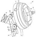
- a wire pulling mechanism 50 is connected to the proximal end side of the bending lever 45 inside the operation unit 3, and the wire pulling mechanism 50 is further connected via a relay lever mechanism 60.
- Each pulling wire 23 is connected.
- the bending lever 45 and the wire pulling mechanism 50 and the relay lever mechanism 60 constitute a bending operation device 70 for bending the bending portion 7 in an arbitrary direction.
- the wire pulling mechanism 50 includes a housing 51, a rotating frame 52 that is rotatably supported in the housing 51, and a rotating frame 52 that rotates in the rotating frame 52.
- the base member 53 is pivotally supported so as to be freely movable (oscillated), and the wire pulling member 54 is fixed to the base member 53.
- the housing 51 is constituted by a substantially cylindrical member, and axial holes 51 a facing each other are formed in the peripheral wall of the housing 51.
- the rotation frame 52 is constituted by a frame body having a substantially rectangular shape, for example.
- the rotating frame 52 has a pair of screw holes 52a facing each other in the center of both ends in the longitudinal direction, and a pair of shaft holes 52b facing each other in the center of both ends in the short direction. ing. Then, the screw 55 inserted into each shaft hole 51 a of the housing 51 is screwed into each screw hole 52 a, so that the rotation frame 52 is pivotally supported with respect to the housing 51.
- the base member 53 is configured by a substantially cylindrical member.
- a bending lever 45 is integrally formed on the central axis of the base member 53.
- a pair of flat portions 53b facing each other are formed in the peripheral portion of the base member 53, and a screw hole 53c penetrating the flat portions 53b is formed. Screws 53 inserted into the respective shaft holes 52b of the rotating frame 52 are screwed into the screw holes 53c, whereby the base member 53 is pivotally supported with respect to the rotating frame 52. Yes.
- the base member 53 is supported by the housing 51 via the rotation frame 52, so that the bending lever 45 integrally connected to the base member 53 tilts in an arbitrary direction. Is possible.
- the wire pulling member 54 is configured by a plate-like member in which the arm portion 54b extends in four different directions. More specifically, in the present embodiment, the wire pulling member 54 is configured by a cross-shaped plate member in which the angle formed by the adjacent arm portions 54b is set to 90 degrees, and the central portion 54a thereof is a screw 57. It is being fixed to the base member 53 via. In other words, the bending lever 45 is connected to the wire pulling member 54 via the base member 53, whereby the distal end side of each arm portion 54 b can be displaced in conjunction with the tilting operation of the bending lever 45. In addition, a wire fixing hole 54c is formed on the distal end side of each arm portion 54b supported in such a manner as to be displaceable.
- the angle formed by each arm portion 54b is not limited to 90 degrees, and can be arbitrarily changed within a range of ⁇ 30 degrees with reference to the 90 degrees.
- the wire pulling mechanism 50 configured as described above is disposed in the operation portion main body 32 so as to face the cylinder 43 in the front-rear direction.
- each arm portion 54b is within a range of 30 to 60 degrees around the central axis Ol of the bending lever 45 with respect to the vertical and horizontal tilt directions defined by the bending lever 45. It is arranged at a position where it is rotated (for example, a position that is rotated 45 degrees).
- the wire pulling mechanism 50 is disposed in a state where the cylinder 43 faces the two arm portions 54 b of the wire pulling member 54.
- the relay lever mechanism 60 includes a pair of left and right stays 61 extending from the operation unit main body 32 into the gripping part 33, and four relay levers supported by these stays 61. 62.
- the relay levers 62 are arranged side by side in the left and right sides in the gripping portion 33, and the fixed end sides of the relay levers 62 are supported so as to be swingable around a single shaft portion 63 installed between the left and right stays 61. Has been.
- relay levers 62 correspond to the arm portions 54 b of the wire pulling mechanism 50, and in the middle of each relay lever 62, the displacement amount of each arm portion 54 b accompanying the tilting operation of the bending lever 45 is the relay wire 65.
- the force point 62a transmitted through the is set. Further, on the free end side of each relay lever 62 located farther from the fulcrum (shaft portion 63) than the force point 62a, an action for amplifying the amount of displacement of each arm portion 54b and transmitting it to each traction wire 23. A point 62b is set.
- the proximal end side of the relay wire 65 is connected to the wire fixing hole 54c of each arm portion 54b.
- the force point 62 a of each relay lever 62 is provided with a screw-type first wire adjusting unit 66 for adjusting the length of the relay wire 65, and the relay is provided via the first wire adjusting unit 66.
- the tip end side of the wire 65 is connected.
- a pulley 68 supported by the operation section main body 32 is engaged in the middle of each relay wire 65.
- each relay wire 65 has an angle (within a predetermined angle range with respect to the vertical direction of the arm portion 54b when the bending lever 45 is in a neutral state, depending on the setting position of each pulley 68, etc. For example, it is adjusted so as to be directed at an angle within an error range of about ⁇ 20 ° with respect to the vertical direction of the arm portion 54b.
- each relay wire 65 has an angle within a predetermined angle range with respect to the vertical direction of the relay lever 62 when the bending lever 45 is in a neutral state (for example, due to the setting position of each pulley 68, for example)
- the angle is within an error range of about ⁇ 20 ° with respect to the vertical direction of the relay lever 62.
- a screw-type second wire adjusting portion 67 for adjusting the length of the pulling wire 23 is provided at the action point 62 b of each relay lever 62.
- the proximal end side of the pulling wire 23 is connected via the second wire adjusting portion 67.
- the front end side of each pulling wire 23 is routed in the insertion portion 2 in a state where the top, bottom, left and right are crossed.
- the two arm portions 54b positioned mainly in the left tilt direction are used.
- the relay wire 65 connected to is pulled.
- the pulling to these relay wires 65 is transmitted to the corresponding relay levers 62, and each relay lever 62 is swung at an angle corresponding to the pulling amount. Accordingly, in the bending portion 7, the two pulling wires 23 positioned mainly on the right side in the bending direction are pulled by the pulling amount amplified by the relay lever 62, and the bending portion 7 is bent to the right side.
- the two arm portions 54b positioned mainly in the downward tilt direction.
- the relay wire 65 connected to is pulled.
- the pulling to these relay wires 65 is transmitted to the corresponding relay levers 62, and each relay lever 62 is swung at an angle corresponding to the pulling amount.
- the two pulling wires 23 positioned mainly on the lower side in the bending direction are pulled by the pulling amount amplified by the relay lever 62, and the bending portion 7 is bent upward.
- the two arm portions 54b positioned mainly in the upward tilt direction.
- the relay wire 65 connected to is pulled.
- the pulling to these relay wires 65 is transmitted to the corresponding relay levers 62, and each relay lever 62 is swung at an angle corresponding to the pulling amount.
- the two pulling wires 23 positioned mainly on the upper side in the bending direction are pulled by the pulling amount amplified by the relay lever 62, and the bending portion 7 is bent downward.
- the bending lever 45 supported to be tiltable with respect to the operation unit 3 of the endoscope 1, and the tip provided in conjunction with the tilting operation of the bending lever 45 provided on the bending lever 45.
- the arm portion 54b whose side is displaceable, and a force point 62a that is connected to the distal end side of the arm portion 54b via the relay wire 65 are supported in the middle, and the bending wire 23 is connected.
- the relay lever 62 having the action point 62b at a position farther from the fulcrum (shaft portion 63) than the force point 62a, thereby constituting the bending operation device 70, thereby making the bending portion without lengthening the arm portion 54b. 7 can be bent at a sufficient bending angle.
- the amount of displacement (traction amount) by the arm portion 54b is amplified by the relay lever 62 and then transmitted to the pulling wire 23, so that the bending portion 7 can be moved with a sufficient pulling amount without increasing the length of the arm portion 54b. It can be bent. Therefore, interference between the arm portion 54b and other built-in objects can be prevented, and further, the enlargement of the operation portion 3 can be effectively suppressed.
- a pulley 68 that engages in the middle of the relay wire 65 is provided, and the pulley 68 directs the proximal end side of the relay wire 65 when the bending lever 45 is in a neutral state to be substantially perpendicular to the arm portion 54b.
- the pulley 68 is set so that the distal end side of the relay wire 65 when the bending lever 45 is in the neutral state is oriented substantially perpendicular to the relay lever 62, so that the traction amount by the relay wire 65 can be efficiently increased. It can be converted into the swing amount of the relay lever 62.
- the inside of the operation portion 3 is provided. Dead space can be used effectively.
- the relay levers 62 can be arranged in one place.
- the length of the first wire adjusting portion 66 for adjusting the length of the relay wire 65 connected to the force point 62 a of each relay lever 62 and the length of the pulling wire 23 connected to the action point 62 b of each relay lever 62 are set.
- the second wire adjustment portion 67 for adjustment in the relay lever mechanism 60 the relationship between the tilting state of the bending lever 45 and the bending state of the bending portion 7 can be easily tuned. That is, in the relay lever mechanism 60 of the present embodiment having the first and second wire adjusting portions 66 and 67, the tilting state and the bending of the bending lever 45 are adjusted by adjusting the length of the relay wire 65 by the first wire adjusting portion 66.
- the relationship with the curved state of the portion 7 can be roughly adjusted, and then the above relationship can be finely adjusted by adjusting the length of the pulling wire 23 by the second wire adjusting portion 67, and the tuning operation can be simplified.
- the relay levers 62 are collectively arranged in the gripping portion 33, and the first and second wire adjusting portions 66 and 67 are connected to the force point 62a and the action point 62b of each relay lever 62.
Landscapes
- Health & Medical Sciences (AREA)
- Life Sciences & Earth Sciences (AREA)
- Physics & Mathematics (AREA)
- Surgery (AREA)
- Optics & Photonics (AREA)
- Biomedical Technology (AREA)
- Public Health (AREA)
- Nuclear Medicine, Radiotherapy & Molecular Imaging (AREA)
- Pathology (AREA)
- Radiology & Medical Imaging (AREA)
- Veterinary Medicine (AREA)
- Engineering & Computer Science (AREA)
- Molecular Biology (AREA)
- Biophysics (AREA)
- Medical Informatics (AREA)
- Heart & Thoracic Surgery (AREA)
- Animal Behavior & Ethology (AREA)
- General Health & Medical Sciences (AREA)
- General Physics & Mathematics (AREA)
- Astronomy & Astrophysics (AREA)
- Instruments For Viewing The Inside Of Hollow Bodies (AREA)
- Endoscopes (AREA)
Abstract
L'invention concerne un dispositif pour opération de flexion 70, comprenant : un levier de flexion 45 supporté avec faculté d'inclinaison sur une partie de manipulation 3 d'un endoscope 1 ; une partie de bras 54b placée sur le levier de flexion à 45, le côté d'extrémité distale de la partie de bras 54b pouvant être déplacé en association avec l'action d'inclinaison du levier de flexion 45 ; et un levier de relais 62 supporté avec faculté d'oscillation sur la partie de manipulation 3, le levier de relais 62 comprenant à mi-chemin un point de puissance 62c auquel le côté d'extrémité distale de la partie de bras 54b est relié par un fil relais 65, et ayant un point de travail 62b auquel un fil de flexion 23 est relié, le point de travail étant situé plus loin du point d'appui (partie d'arbre 63) que le point de puissance 62a.
Priority Applications (4)
| Application Number | Priority Date | Filing Date | Title |
|---|---|---|---|
| JP2016544634A JP6076556B1 (ja) | 2015-03-18 | 2015-10-09 | 湾曲操作装置及び内視鏡 |
| CN201580056791.2A CN107072481B (zh) | 2015-03-18 | 2015-10-09 | 弯曲操作装置和内窥镜 |
| EP15885549.4A EP3192426A4 (fr) | 2015-03-18 | 2015-10-09 | Dispositif pour opération de flexion et endoscope |
| US15/486,944 US10136800B2 (en) | 2015-03-18 | 2017-04-13 | Bending operation device and endoscope |
Applications Claiming Priority (2)
| Application Number | Priority Date | Filing Date | Title |
|---|---|---|---|
| JP2015-055174 | 2015-03-18 | ||
| JP2015055174 | 2015-03-18 |
Related Child Applications (1)
| Application Number | Title | Priority Date | Filing Date |
|---|---|---|---|
| US15/486,944 Continuation US10136800B2 (en) | 2015-03-18 | 2017-04-13 | Bending operation device and endoscope |
Publications (1)
| Publication Number | Publication Date |
|---|---|
| WO2016147457A1 true WO2016147457A1 (fr) | 2016-09-22 |
Family
ID=56918637
Family Applications (1)
| Application Number | Title | Priority Date | Filing Date |
|---|---|---|---|
| PCT/JP2015/078766 Ceased WO2016147457A1 (fr) | 2015-03-18 | 2015-10-09 | Dispositif pour opération de flexion et endoscope |
Country Status (5)
| Country | Link |
|---|---|
| US (1) | US10136800B2 (fr) |
| EP (1) | EP3192426A4 (fr) |
| JP (1) | JP6076556B1 (fr) |
| CN (1) | CN107072481B (fr) |
| WO (1) | WO2016147457A1 (fr) |
Cited By (2)
| Publication number | Priority date | Publication date | Assignee | Title |
|---|---|---|---|---|
| WO2018092476A1 (fr) * | 2016-11-17 | 2018-05-24 | オリンパス株式会社 | Instrument médical |
| WO2021070389A1 (fr) * | 2019-10-11 | 2021-04-15 | オリンパス株式会社 | Mécanisme d'opération de flexion pour endoscope |
Families Citing this family (7)
| Publication number | Priority date | Publication date | Assignee | Title |
|---|---|---|---|---|
| CN106659363B (zh) * | 2015-03-12 | 2018-06-22 | 奥林巴斯株式会社 | 内窥镜操作部和内窥镜 |
| JP6116777B1 (ja) * | 2015-06-08 | 2017-04-19 | オリンパス株式会社 | 湾曲操作装置および内視鏡 |
| KR102562929B1 (ko) * | 2015-08-11 | 2023-08-03 | 휴먼 엑스텐션스 리미티드 | 가요성 내시경용 제어 유닛 |
| JP6360639B1 (ja) * | 2016-12-26 | 2018-07-18 | オリンパス株式会社 | 内視鏡 |
| JP3215550U (ja) * | 2017-01-25 | 2018-03-29 | 珠海嘉潤医用影像科技有限公司Zhuhai Kaden Medical Imaging Technology Co., Ltd | 気管支鏡の引張コードのための制御機構 |
| WO2018154824A1 (fr) * | 2017-02-22 | 2018-08-30 | オリンパス株式会社 | Unité d'actionnement d'endoscope et endoscope la comprenant |
| JP7329428B2 (ja) * | 2019-12-04 | 2023-08-18 | Hoya株式会社 | 内視鏡装置 |
Citations (5)
| Publication number | Priority date | Publication date | Assignee | Title |
|---|---|---|---|---|
| JPS645523A (en) * | 1987-06-29 | 1989-01-10 | Asahi Optical Co Ltd | Curving operating apparatus of endoscope |
| JP2001000384A (ja) * | 1999-06-23 | 2001-01-09 | Toshiba Corp | 内視鏡装置 |
| JP2004321697A (ja) * | 2003-04-28 | 2004-11-18 | Olympus Corp | 内視鏡 |
| JP2004321492A (ja) * | 2003-04-24 | 2004-11-18 | Olympus Corp | 内視鏡 |
| JP2009101076A (ja) * | 2007-10-25 | 2009-05-14 | Olympus Corp | 牽引部材操作装置及び内視鏡装置 |
Family Cites Families (9)
| Publication number | Priority date | Publication date | Assignee | Title |
|---|---|---|---|---|
| US5549542A (en) * | 1992-11-17 | 1996-08-27 | Life Medical Technologies, Inc. | Deflectable endoscope |
| US5667476A (en) * | 1995-06-05 | 1997-09-16 | Vision-Sciences, Inc. | Endoscope articulation system to reduce effort during articulation of an endoscope |
| JPH11216103A (ja) * | 1998-02-03 | 1999-08-10 | Mitsubishi Cable Ind Ltd | 首振機構 |
| JP3917894B2 (ja) | 2002-05-17 | 2007-05-23 | オリンパス株式会社 | 牽引部材操作装置 |
| JP4981379B2 (ja) * | 2006-08-01 | 2012-07-18 | オリンパス株式会社 | 内視鏡 |
| WO2013011771A1 (fr) * | 2011-07-15 | 2013-01-24 | オリンパスメディカルシステムズ株式会社 | Instrument d'introduction |
| EP2805664A4 (fr) * | 2012-01-16 | 2015-09-02 | Olympus Medical Systems Corp | Endoscope |
| JP5416324B1 (ja) * | 2012-04-06 | 2014-02-12 | オリンパスメディカルシステムズ株式会社 | 挿入機器 |
| WO2014123245A1 (fr) * | 2013-02-08 | 2014-08-14 | Olympus Corp. | Manipulateur |
-
2015
- 2015-10-09 WO PCT/JP2015/078766 patent/WO2016147457A1/fr not_active Ceased
- 2015-10-09 EP EP15885549.4A patent/EP3192426A4/fr not_active Withdrawn
- 2015-10-09 JP JP2016544634A patent/JP6076556B1/ja active Active
- 2015-10-09 CN CN201580056791.2A patent/CN107072481B/zh active Active
-
2017
- 2017-04-13 US US15/486,944 patent/US10136800B2/en active Active
Patent Citations (5)
| Publication number | Priority date | Publication date | Assignee | Title |
|---|---|---|---|---|
| JPS645523A (en) * | 1987-06-29 | 1989-01-10 | Asahi Optical Co Ltd | Curving operating apparatus of endoscope |
| JP2001000384A (ja) * | 1999-06-23 | 2001-01-09 | Toshiba Corp | 内視鏡装置 |
| JP2004321492A (ja) * | 2003-04-24 | 2004-11-18 | Olympus Corp | 内視鏡 |
| JP2004321697A (ja) * | 2003-04-28 | 2004-11-18 | Olympus Corp | 内視鏡 |
| JP2009101076A (ja) * | 2007-10-25 | 2009-05-14 | Olympus Corp | 牽引部材操作装置及び内視鏡装置 |
Non-Patent Citations (1)
| Title |
|---|
| See also references of EP3192426A4 * |
Cited By (6)
| Publication number | Priority date | Publication date | Assignee | Title |
|---|---|---|---|---|
| WO2018092476A1 (fr) * | 2016-11-17 | 2018-05-24 | オリンパス株式会社 | Instrument médical |
| JP6395989B1 (ja) * | 2016-11-17 | 2018-09-26 | オリンパス株式会社 | 医療器具 |
| CN109715031A (zh) * | 2016-11-17 | 2019-05-03 | 奥林巴斯株式会社 | 医疗器具 |
| CN109715031B (zh) * | 2016-11-17 | 2021-10-15 | 奥林巴斯株式会社 | 医疗器具 |
| WO2021070389A1 (fr) * | 2019-10-11 | 2021-04-15 | オリンパス株式会社 | Mécanisme d'opération de flexion pour endoscope |
| US12465203B2 (en) | 2019-10-11 | 2025-11-11 | Olympus Corporation | Bending operation mechanism for endoscope, and endoscope |
Also Published As
| Publication number | Publication date |
|---|---|
| US10136800B2 (en) | 2018-11-27 |
| JP6076556B1 (ja) | 2017-02-08 |
| US20170215697A1 (en) | 2017-08-03 |
| EP3192426A1 (fr) | 2017-07-19 |
| CN107072481B (zh) | 2018-12-18 |
| CN107072481A (zh) | 2017-08-18 |
| EP3192426A4 (fr) | 2018-07-04 |
| JPWO2016147457A1 (ja) | 2017-04-27 |
Similar Documents
| Publication | Publication Date | Title |
|---|---|---|
| JP6076556B1 (ja) | 湾曲操作装置及び内視鏡 | |
| JP5930255B2 (ja) | 内視鏡 | |
| JP6116777B1 (ja) | 湾曲操作装置および内視鏡 | |
| JP6081684B1 (ja) | 内視鏡 | |
| CN110730629B (zh) | 内窥镜的操作单元 | |
| JP6301014B2 (ja) | 湾曲操作装置および内視鏡 | |
| WO2018029916A1 (fr) | Endoscope | |
| WO2021070389A1 (fr) | Mécanisme d'opération de flexion pour endoscope | |
| US11064872B2 (en) | Bending operation device and endoscope with the same applied thereto | |
| JP7145982B2 (ja) | 内視鏡 | |
| WO2017145431A1 (fr) | Endoscope |
Legal Events
| Date | Code | Title | Description |
|---|---|---|---|
| ENP | Entry into the national phase |
Ref document number: 2016544634 Country of ref document: JP Kind code of ref document: A |
|
| 121 | Ep: the epo has been informed by wipo that ep was designated in this application |
Ref document number: 15885549 Country of ref document: EP Kind code of ref document: A1 |
|
| REEP | Request for entry into the european phase |
Ref document number: 2015885549 Country of ref document: EP |
|
| NENP | Non-entry into the national phase |
Ref country code: DE |