WO2016148065A1 - Dispositif de transfert de chaleur pour refroidissement - Google Patents
Dispositif de transfert de chaleur pour refroidissement Download PDFInfo
- Publication number
- WO2016148065A1 WO2016148065A1 PCT/JP2016/057788 JP2016057788W WO2016148065A1 WO 2016148065 A1 WO2016148065 A1 WO 2016148065A1 JP 2016057788 W JP2016057788 W JP 2016057788W WO 2016148065 A1 WO2016148065 A1 WO 2016148065A1
- Authority
- WO
- WIPO (PCT)
- Prior art keywords
- refrigerant circulation
- circulation frame
- cooling
- heat
- frame
- Prior art date
- Legal status (The legal status is an assumption and is not a legal conclusion. Google has not performed a legal analysis and makes no representation as to the accuracy of the status listed.)
- Ceased
Links
Images





Classifications
-
- B—PERFORMING OPERATIONS; TRANSPORTING
- B21—MECHANICAL METAL-WORKING WITHOUT ESSENTIALLY REMOVING MATERIAL; PUNCHING METAL
- B21D—WORKING OR PROCESSING OF SHEET METAL OR METAL TUBES, RODS OR PROFILES WITHOUT ESSENTIALLY REMOVING MATERIAL; PUNCHING METAL
- B21D53/00—Making other particular articles
- B21D53/02—Making other particular articles heat exchangers or parts thereof, e.g. radiators, condensers fins, headers
- B21D53/04—Making other particular articles heat exchangers or parts thereof, e.g. radiators, condensers fins, headers of sheet metal
-
- F—MECHANICAL ENGINEERING; LIGHTING; HEATING; WEAPONS; BLASTING
- F28—HEAT EXCHANGE IN GENERAL
- F28D—HEAT-EXCHANGE APPARATUS, NOT PROVIDED FOR IN ANOTHER SUBCLASS, IN WHICH THE HEAT-EXCHANGE MEDIA DO NOT COME INTO DIRECT CONTACT
- F28D15/00—Heat-exchange apparatus with the intermediate heat-transfer medium in closed tubes passing into or through the conduit walls ; Heat-exchange apparatus employing intermediate heat-transfer medium or bodies
- F28D15/02—Heat-exchange apparatus with the intermediate heat-transfer medium in closed tubes passing into or through the conduit walls ; Heat-exchange apparatus employing intermediate heat-transfer medium or bodies in which the medium condenses and evaporates, e.g. heat pipes
-
- H—ELECTRICITY
- H05—ELECTRIC TECHNIQUES NOT OTHERWISE PROVIDED FOR
- H05K—PRINTED CIRCUITS; CASINGS OR CONSTRUCTIONAL DETAILS OF ELECTRIC APPARATUS; MANUFACTURE OF ASSEMBLAGES OF ELECTRICAL COMPONENTS
- H05K7/00—Constructional details common to different types of electric apparatus
- H05K7/20—Modifications to facilitate cooling, ventilating, or heating
-
- H—ELECTRICITY
- H10—SEMICONDUCTOR DEVICES; ELECTRIC SOLID-STATE DEVICES NOT OTHERWISE PROVIDED FOR
- H10W—GENERIC PACKAGES, INTERCONNECTIONS, CONNECTORS OR OTHER CONSTRUCTIONAL DETAILS OF DEVICES COVERED BY CLASS H10
- H10W40/00—Arrangements for thermal protection or thermal control
- H10W40/40—Arrangements for thermal protection or thermal control involving heat exchange by flowing fluids
- H10W40/43—Arrangements for thermal protection or thermal control involving heat exchange by flowing fluids by flowing gases, e.g. forced air cooling
-
- H—ELECTRICITY
- H10—SEMICONDUCTOR DEVICES; ELECTRIC SOLID-STATE DEVICES NOT OTHERWISE PROVIDED FOR
- H10W—GENERIC PACKAGES, INTERCONNECTIONS, CONNECTORS OR OTHER CONSTRUCTIONAL DETAILS OF DEVICES COVERED BY CLASS H10
- H10W40/00—Arrangements for thermal protection or thermal control
- H10W40/70—Fillings or auxiliary members in containers or in encapsulations for thermal protection or control
- H10W40/73—Fillings or auxiliary members in containers or in encapsulations for thermal protection or control for cooling by change of state
Definitions
- the present invention is directed to a cooling heat transfer device in which a refrigerant circulation frame is provided radially in order to cool the heat transferred from the heating element.
- the transmitted heat is about to be conducted in the same direction along the contact surface.
- the heat-dissipating fins 2 are provided so as to protrude above the radial plane, and the cooling air from the fan Even though it enters the area sandwiched between the two, it is impossible to move in the plane direction. By filling the area where the heat pipe is installed, backflow is generated on the blower side, and efficient cooling is performed. I can't.
- the present invention achieves a high cooling effect by transferring the heat transferred from the heating element in a radial manner while reducing the degree of back wind generated even when cooling air is blown to the heat pipe. It is an object of the present invention to provide a configuration of a heat transfer device for cooling that can be performed.
- the basic configuration of the present invention is as follows. (1) Two or more radial refrigerant circulation frames are arranged radially from a central refrigerant circulation frame disposed at or near the central position in the planar direction along the direction in which the bonding surface for the heating element can be formed.
- the central refrigerant circulation frame and the radial refrigerant circulation frame form a heat pipe by connecting the adjacent areas to each other, and each radial refrigerant circulation frame, or each radial refrigerant circulation frame and the central refrigerant circulation frame A heat exchanger for cooling, in which the fins for heat cooling are laid in a state where a gap is formed between the fins in the plane direction in a region sandwiched between (2)
- Two or more radial refrigerant circulation frames are arranged radially from a central refrigerant circulation frame disposed at or near the central position in the planar direction along the direction in which the bonding surface for the heating element can be formed.
- an outer refrigerant circulation frame is arranged around the outside of each radial refrigerant circulation frame, the central refrigerant circulation frame and the radial refrigerant circulation frame are in communication with each other in the adjacent region, and the radial refrigerant circulation frame and the outer refrigerant circulation are provided.
- the frame forms a heat pipe by connecting the adjacent areas to each other, and between each outer refrigerant circulation frame and each radial refrigerant circulation frame, or each outer refrigerant circulation frame and each radial refrigerant circulation frame, and A heat exchanger for cooling, in which heat sink fins are installed in a state surrounded by a central refrigerant circulation frame so as to form a gap between the fins along the plane direction; Consists of.
- the heat transferred from the heating element is transferred to the radial refrigerant circulation frame, so that the object to be cooled is compared with those of Patent Documents 1 and 2.
- the cooling air is heat that forms a gap in the plane direction.
- it is possible to achieve efficient thermal cooling after setting the state where the back wind is generated to be extremely low as compared with the case of Patent Documents 3 and 4.
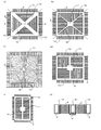
- FIG. 1 shows a basic configuration (1), (a), (b), (c), (d), and (e) are plan views, and (f) is a cross-section along AA in (a).
- FIG. 2 shows a basic configuration (2), wherein (a), (b), (c), (d), (e) are plan views, and (f) is a cross section taken along line AA in (a).
- coolant circulation frame is shown, (a) is a top view at the time of forming the uneven surface curved along the plane direction, (b) is a plane direction It is a top view at the time of forming a polygonal uneven surface along, and (c) and (d) form an uneven surface which has a portion which intersects perpendicularly with a longitudinal direction along a direction perpendicular to the plane direction and the plane direction. It is drawing of the direction orthogonal to the plane view and elevation in the case where it did, ie, the said plane direction.
- the radial refrigerant circulation frame of the basic configuration (1) and the radial refrigerant circulation frame and the outer refrigerant circulation frame of the basic configuration (2) include a meandering state, a parallel line shape, or a region perpendicular to the longitudinal direction.
- the embodiment made into the zigzag state is shown, (a) is a meandering top view, (b) is a polygonal plan view, and (c) is a zigzag plan view.
- the embodiment which the unevenness surface formed the fin for heat cooling has shown, (a) shows the case of the uneven surface along a plane direction, (b) shows the case of the uneven surface of the direction orthogonal to the said plane direction Indicates.
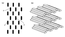
- the heat-dissipating fin is divided by a plurality of plate-like pieces in a direction perpendicular to the plane direction, and adjacent plate-like pieces in the direction perpendicular to the plane direction are set at different positions along the plane direction.
- 1A is a sectional view in a direction orthogonal to the planar direction
- FIG. 2B is a partial perspective view.
- coolant circulation frame is shown, (a) is a top view, (b) is a sectional side view. The sectional side view at the time of laminating
- the side sectional view of the embodiment in which the fan is provided on the side where the heating element does not exist is shown, and the dotted line on the right side shows the fixing mesh laid between the fan housing fixing frame and the central axis, A solid line indicates a beam constructed between the fan housing fixing frame and the central axis.
- the perspective view which shows the process of Example 1 which manufactures the heat transfer device for natural cooling of basic composition (1) is shown.
- the perspective view which shows the process of Example 2 which manufactures the heat exchanger for natural cooling of a basic composition (2) is shown.
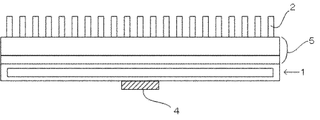
- the side view which shows the structure of a prior art is shown.
- the basic configuration (1) receives heat from the heating element 4 and has a planar direction.
- Two or more radial refrigerant circulation frames 12 are arranged radially with respect to the central refrigerant circulation frame 11 arranged at or near the center position thereof, with the adjacent regions communicating with each other.
- the heat-dissipating fins 2 are installed in a region sandwiched between the radial refrigerant circulation frames 12, or shown in FIGS. 1 (b), (c), and (d).
- the heat cooling fins 2 are installed, or as shown in FIG. 12 and a region not sandwiched between the central refrigerant circulation frame 11 (however, when there are two radial refrigerant circulation frames 12) It has been set.
- the heat cooling fin 2 is formed with a gap through which the cooling air passes along the plane direction.
- FIG. 1A shows a construction state in which both end portions of the heat-dissipating fins 2 are in contact with each radial refrigerant circulation frame 12 between the radial refrigerant circulation frames 12.
- (C), (d), (e), and (f) show a case where one end of the heat cooling fin 2 is in contact with each radial refrigerant circulation frame 12 and the central refrigerant circulation frame 11.
- the contact state can be arbitrarily selected.
- the basic configuration (2) includes a central refrigerant circulation frame that receives heat from the heating element 4, as shown in FIGS. 2 (a), (b), (c), (d), (e), and (f). 11, two or more radial refrigerant circulation frames 12 are arranged with their adjacent regions in communication with each other, and an outer refrigerant circulation frame 13 is arranged around the outer periphery of the tip of each radial refrigerant circulation frame 12. As shown in FIG. 2 (a), the heat cooling fin 2 is provided for heat cooling in a region surrounded by each outer refrigerant circulation frame 13 and each radial refrigerant circulation frame 12. 2 is installed, or as shown in FIGS.
- each outer refrigerant circulation frame 13 each radial refrigerant circulation frame 12, and the central refrigerant circulation frame 11 are provided.
- the heat-dissipating fins 2 are erected in a region surrounded by.
- FIG. FIG. 2B, FIG. 2D, and FIG. 2E show the case where one end of the heat-dissipating fin 2 is in contact with each radial refrigerant circulation frame 12.
- FIG. FIG. 2C shows the case where each outer refrigerant circulation frame 13 is in contact with each radial refrigerant circulation frame 12 and the central refrigerant circulation frame 11, and FIG. The case where it contacts with the circulation frame 13 and each radial refrigerant circulation frame 12 and the central refrigerant circulation frame 11 is shown, and any of such contact states can be selected.
- the heat-cooling fins 2 are used as outer refrigerants.
- a configuration that further promotes cooling efficiency is adopted by adopting an embodiment characterized in that it is provided on the outer side of the circulation frame 13.
- Ring in the basic configurations (1) and (2) refers to a state in which the radial refrigerant circulation frame 12 extends in two or more directions with respect to the central refrigerant circulation frame 11.
- Near position means that a state in which the heat transfer state in the radial refrigerant circulation frame 12 extending in two or more directions is almost uniform can be realized.
- the heat-dissipating fins 2 (in the case of the basic configuration (1)) and the outer refrigerant circulation frame 13 (in the case of the basic configuration (2)) that join the outer ends of the radial refrigerant circulation frame 12 are linear or curved. Any of these can be adopted, for example, a curved shape as shown in FIGS. 1A and 1C, a straight shape as shown in FIGS. 1B and 2A, 2B and 2C, Any of the intersecting linear shapes as shown in FIGS. 1D and 1E and FIGS. 2D and 2E can be adopted.
- the heat-dissipating fins 2 forming the outermost region form polygonal (rectangular or triangular) sides as shown in FIGS. 1B, 1D, and 1E
- the outer refrigerant circulation frame 13 forms a polygonal (rectangular) side as shown in FIGS. 2A, 2B, 2C, 2D, and 2E
- the radial refrigerant circulation frame 12 is 1 (b), 2 (a), 2 (b), and 2 (c), the configuration extending to the polygonal corner, and FIGS. 1 (d), 1 (e), and 2 (c).
- any of the configurations extending to the middle part of each side can be selected as the “radial” mode.
- FIG. 1 (d) shows a case where there are three radial refrigerant circulation frames 12
- FIGS. 1 (e) and 2 (e) show a case where there are two radial refrigerant circulation frames 12. Any of these embodiments tends to be employed when such a number of radial refrigerant circulation frames 12 have to be employed because of the space for installing the heat exchanger for cooling.
- the refrigerant circulation frames in the basic configurations (1) and (2) are both in a vacuum state, the refrigerant is in a liquid state on the lower side, and the liquid refrigerant evaporates by heat transmitted from the heating element 4,
- the upper side is filled with the vapor, and a mutual circulation state is realized by the rise accompanying the evaporation of the lower liquid and the fall accompanying the liquefaction of the upper vapor.
- a plurality of refrigerant circulation frames are provided radially, so that heat pipes 1 on both sides in the longitudinal direction of the heating element 4 are heated as in Patent Documents 1 and 2, respectively.
- the heat is diffused through the communication state of the areas adjacent to the at least three or more radial refrigerant circulation frames 12, so that the cooling target area via the heat cooling fins 2 is reduced. It can be enlarged, and as a result, efficient cooling of the heat can be realized.
- the total amount of heat Q transferred from the central refrigerant circulation frame 11 to the refrigerant in each radial refrigerant circulation frame 12 is:
- N 2 because heat is sequentially transferred in the longitudinal direction on both sides of the heating element 4, whereas in the case of the basic configurations (1) and (2), N Since ⁇ 3, it is possible to expand the heat transfer area to be cooled via the heat-dissipating fins 2 and to set a large amount of heat energy for cooling.
- the inner side surfaces of all or any of the radial refrigerant circulation frame 12 according to claim 1 and the radial refrigerant circulation frame 12 according to claim 2 and the outer refrigerant circulation frame 13 are longitudinal in the plane direction.
- a curved uneven surface is formed, or as shown in FIG. 3B, a polygonal curved surface is formed, or as shown in FIG. 3C.
- an embodiment characterized by forming an uneven surface having a region portion orthogonal to the longitudinal direction can be adopted.
- the central refrigerant circulation frame 11 and the radial refrigerant circulation frame 12 according to claim 1 and the central refrigerant circulation frame 11 and the radial refrigerant circulation frame 12 according to claim 2.
- the area of the wall portion increases, and as a result, the amount of heat transferred to the installed heat-dissipating fin 2 And the cooling efficiency can be improved.
- all or a part of the inner surface of the wall part forms an uneven surface due to a meandering state curved as shown in FIG. 4A along the longitudinal direction in the plane direction, or As shown in FIG. 4 (b), a concavo-convex surface with parallel broken lines is formed, or as shown in FIG. 4 (c), a concavo-convex surface with a region portion orthogonal to the longitudinal direction is formed.
- the distance between the radial refrigerant circulation frame 12 and / or the outer refrigerant circulation frame 13 is increased.
- the installed cooling fin is The amount of heat to be transmitted can be increased and efficient cooling efficiency can be achieved.
- the heat-dissipating fin 2 forms an uneven surface along the plane direction as shown in FIG. 5A, or as shown in FIG. 5B.
- an embodiment in which an uneven surface is formed along a direction orthogonal to the planar direction can be employed.
- FIG. 5A shows the case of a curved uneven surface
- FIG. 5B shows the case of a zigzag uneven surface by bending, but in these embodiments, the area of the fin is enlarged. Thus, the cooling efficiency can be improved.
- the heat-dissipating fins 2 form a plurality of plate-like pieces along the direction orthogonal to the planar direction.
- the embodiment is characterized in that the adjacent plate-like pieces are arranged at different positions along the plane direction.
- FIG. 6A shows an embodiment in which the direction perpendicular to the plane direction is thicker than the plane direction
- FIG. 6B shows the embodiment in which the plane direction is thicker than the direction perpendicular to the plane direction.
- the cooling air that has passed through the gap in a predetermined stage in the vertical direction is shown as having a thickness and the end portions exhibit a pair of coupled states along the planar direction.
- a turbulent flow is formed by colliding with the heat-dissipating fins 2 and the contact time with the cooling air is prolonged as compared with the flat heat-dissipating fins 2. Can be improved.
- the evaporated refrigerant collides with the beam forming the grid, and as a result, the heat-cooling fins installed between the refrigerant circulation frames.
- the amount of heat transferred to 2 can be increased, and the cooling effect can be further improved.
- FIG. 8 shows the laminated state in the basic configuration (2), but the same laminated state can naturally be adopted in the basic configuration (1).
- corresponds to a part of heat exchanger for cooling.
- the heating element 4 is in contact, and further, a stacked state in which the heating element 4 is in contact with the lowermost heat transfer device for cooling.
- the cooling area can be expanded and further improvement in cooling efficiency can be achieved.
- any of the basic configurations (1) and (2) an embodiment is adopted in which a refrigerant inlet is provided at a position opposite to the heating element 4 in the central refrigerant circulation frame 11.
- a refrigerant inlet is provided at a position opposite to the heating element 4 in the central refrigerant circulation frame 11.
- the cooling heat transfer device includes a case in which a fan for circulating cooling air between the heat cooling fins 2 is installed on the side where the heating element 4 is bonded, or on the opposite side. Both of the cases where they are not installed at these positions can be employed.
- the fan 6 is often installed on the side where the heating element 4 is not bonded.
- a fan housing fixing frame 81 is provided around the outside of the fan 6, and the fan housing fixing frame 81 and the fan 6 are provided.
- a fixing mesh 71 or a plurality of beams 72 are installed between the rotating shaft 91 and a central shaft 92 that rotatably supports the rotating shaft 91, while the cooling heat transfer device is supported around the outside of the cooling heat transfer device.
- the fixed frame 82 is provided and both the fixed frames are joined via the spacer 10 is adopted.
- each refrigerant circulation frame forms a hollow state inside, it is impossible to mold at once.
- the first embodiment is characterized in that a heat-cooling transmitter having a basic configuration (1) based on a manufacturing process according to the following order is manufactured.
- a heat-cooling transmitter having a basic configuration (1) based on a manufacturing process according to the following order is manufactured.
- (1) By the surface plate for the central refrigerant circulation frame 11 located on the side opposite to the side in contact with the heating element 4, the surface plate for the radial refrigerant circulation frame 12, A step of forming a single bonding surface plate to be formed by a die, a punching press, or etching; (2) A plurality of combined intermediate plates formed by an inner intermediate plate-like piece for the central refrigerant circulation frame 11, an intermediate plate-like piece for the radial refrigerant circulation frame 12, and a cooling fin plate-like piece to be installed.
- a mold or a punching press, or a process of forming by etching (3) Consists of a back plate for the central refrigerant circulation frame 11 located on the side in contact with the heating element 4, a back plate for the radial refrigerant circulation frame 12, and plate-like pieces of the heat-dissipating fins 2 that are installed.
- Forming one bonded back plate to be molded by a die, a punching press, or etching (4) (1) one coupling surface plate, (2) plural coupling intermediate plates, and (3) one coupling back plate are sequentially laminated and tightened or joined by screws. The process of adhering to each other by welding accompanying the diffusion of the melted components.
- the heat exchanger for cooling of the basic configuration (1) with each refrigerant circulation frame having a hollow state can be efficiently manufactured.
- the second embodiment is characterized in that a heat-cooling transmitter having a basic configuration (2) based on a manufacturing process according to the following order is manufactured.
- a surface plate for the central refrigerant circulation frame 11 located on the side opposite to the side in contact with the heating element 4, a surface plate for the radial refrigerant circulation frame 12, a surface plate for the outer refrigerant circulation frame 13, and the installed heat Forming one surface plate for bonding constituted by plate-like pieces for cooling fins 2 by a die, a punching press, or etching;
- Example 1 and 2 is naturally applicable also to each embodiment as shown in FIGS.
- the present invention can realize efficient air cooling in an apparatus having many heating elements such as an automobile and a computer, and its utility value is tremendous.
Landscapes
- Engineering & Computer Science (AREA)
- Mechanical Engineering (AREA)
- Physics & Mathematics (AREA)
- Thermal Sciences (AREA)
- Microelectronics & Electronic Packaging (AREA)
- Life Sciences & Earth Sciences (AREA)
- Sustainable Development (AREA)
- General Engineering & Computer Science (AREA)
- Cooling Or The Like Of Semiconductors Or Solid State Devices (AREA)
- Cooling Or The Like Of Electrical Apparatus (AREA)
Abstract
Le problème décrit par l'invention cest de fournir une configuration pour dispositif de transfert de chaleur pour refroidissement qui permet d'obtenir une grande efficacité de refroidissement par configuration de tubes chauffants et d'ailettes de refroidissement de dissipation de chaleur entre les tubes chauffants qui présentent une plus grande région de refroidissement que des tubes chauffants définis dans le sens longitudinal, et de générer sensiblement moins de contre-courant même lorsque de l'air de refroidissement est soufflé. L'invention concerne un dispositif de transfert de chaleur pour refroidissement, qui permet de résoudre le problème précité, en utilisant un tube chauffant (1) qui comprend deux grilles de circulation de réfrigérant radiales ou plus (12) disposées radialement en état de communication depuis une grille de circulation de réfrigérant centrale (11) ou un tube chauffant (1) qui comprend deux grilles de circulation de réfrigérant radiales ou plus (12) disposées radialement en état de communication depuis une grille de circulation de réfrigérant externe (13) qui comporte deux ou plusieurs grilles de circulation de réfrigérant radiales (12) disposées radialement en état de communication depuis une grille de circulation de réfrigérant centrale (11) et une grille de circulation de réfrigérant externe (13) disposée en état de communication sur l'extérieur de chaque grille de circulation de réfrigérant radiale (12). Les ailettes de refroidissement de dissipation de chaleur (2) sont disposées dans une région qui est prise en sandwich ou entourée par chaque grille de circulation de réfrigérant de façon à être dans un état tel que des espaces sont formés entre ceux-ci dans le plan par rapport à un élément de chauffage.
Priority Applications (1)
| Application Number | Priority Date | Filing Date | Title |
|---|---|---|---|
| JP2016540055A JP6454915B2 (ja) | 2015-03-13 | 2016-03-11 | 放冷用熱伝達器 |
Applications Claiming Priority (6)
| Application Number | Priority Date | Filing Date | Title |
|---|---|---|---|
| JP2015-050281 | 2015-03-13 | ||
| JP2015050281 | 2015-03-13 | ||
| JP2015179601 | 2015-09-11 | ||
| JP2015-179601 | 2015-09-11 | ||
| JP2016043510 | 2016-03-07 | ||
| JP2016-043510 | 2016-03-07 |
Publications (1)
| Publication Number | Publication Date |
|---|---|
| WO2016148065A1 true WO2016148065A1 (fr) | 2016-09-22 |
Family
ID=56920111
Family Applications (1)
| Application Number | Title | Priority Date | Filing Date |
|---|---|---|---|
| PCT/JP2016/057788 Ceased WO2016148065A1 (fr) | 2015-03-13 | 2016-03-11 | Dispositif de transfert de chaleur pour refroidissement |
Country Status (2)
| Country | Link |
|---|---|
| JP (1) | JP6454915B2 (fr) |
| WO (1) | WO2016148065A1 (fr) |
Cited By (2)
| Publication number | Priority date | Publication date | Assignee | Title |
|---|---|---|---|---|
| US20150296662A1 (en) * | 2014-04-10 | 2015-10-15 | Advanced Thermal Solutions, Inc. | Multiple Flow Entrance Heat sink |
| CN117261227A (zh) * | 2023-08-21 | 2023-12-22 | 贵州大学 | 一种基于3d打印骨架的热界面材料的制备方法及热界面材料 |
Citations (8)
| Publication number | Priority date | Publication date | Assignee | Title |
|---|---|---|---|---|
| JPH05275584A (ja) * | 1992-03-26 | 1993-10-22 | Toshiba Corp | 冷却装置および小型電子機器 |
| JP2004071636A (ja) * | 2002-08-01 | 2004-03-04 | Fujikura Ltd | ファン付きヒートシンク |
| JP2004311718A (ja) * | 2003-04-07 | 2004-11-04 | Furukawa Electric Co Ltd:The | ヒートシンク |
| JP2008535278A (ja) * | 2005-04-11 | 2008-08-28 | ジャルマン テック カンパニー リミテッド | コンピュータ部品用冷却装置及びその製造方法 |
| CN101516171A (zh) * | 2008-02-22 | 2009-08-26 | 富准精密工业(深圳)有限公司 | 散热装置 |
| JP3166568U (ja) * | 2010-12-27 | 2011-03-10 | 洪 進興 | 径方向排流機能を備えたヒートパイプ |
| WO2011136362A1 (fr) * | 2010-04-28 | 2011-11-03 | 株式会社 豊田自動織機 | Dispositif de dissipation de chaleur et dispositif à semiconducteur |
| JP2011222624A (ja) * | 2010-04-06 | 2011-11-04 | Atect Corp | 基板及び基板の製造方法 |
Family Cites Families (16)
| Publication number | Priority date | Publication date | Assignee | Title |
|---|---|---|---|---|
| JPS599832B2 (ja) * | 1978-03-20 | 1984-03-05 | 日立造船株式会社 | 醗酵槽 |
| JP3876490B2 (ja) * | 1997-03-07 | 2007-01-31 | 株式会社デンソー | 沸騰冷却装置及びその製造方法 |
| US6419009B1 (en) * | 1997-08-11 | 2002-07-16 | Christian Thomas Gregory | Radial flow heat exchanger |
| US6397941B1 (en) * | 1999-12-01 | 2002-06-04 | Cool Options, Inc. | Net-shape molded heat exchanger |
| JP4423792B2 (ja) * | 2000-09-14 | 2010-03-03 | 株式会社デンソー | 沸騰冷却装置 |
| JP2003083688A (ja) * | 2001-09-07 | 2003-03-19 | Furukawa Electric Co Ltd:The | フィン一体型平面型ヒートパイプおよびその製造方法 |
| JP3086847U (ja) * | 2001-12-20 | 2002-07-05 | ▲天▼來 王 | ファン付きヒートシンク |
| JP2003258475A (ja) * | 2002-02-28 | 2003-09-12 | Denso Corp | 沸騰冷却装置 |
| JP2009068836A (ja) * | 2002-08-07 | 2009-04-02 | Denso Corp | 対向振動流型熱輸送装置および冷却装置 |
| CN2591776Y (zh) * | 2002-12-06 | 2003-12-10 | 威盛电子股份有限公司 | 薄型平面热管散热器 |
| US7128135B2 (en) * | 2004-11-12 | 2006-10-31 | International Business Machines Corporation | Cooling device using multiple fans and heat sinks |
| RU2007129729A (ru) * | 2005-01-03 | 2009-02-10 | НОЙЗ ЛИМИТ АпС (DK) | Многоориентационная система охлаждения с пузырьковым насосом |
| CA2644762A1 (fr) * | 2006-04-03 | 2007-10-11 | Fuchigami Micro Co., Ltd. | Caloduc |
| WO2008133594A2 (fr) * | 2007-04-27 | 2008-11-06 | National University Of Singapore | Dispositif de refroidissement pour des composants électroniques |
| US7802616B2 (en) * | 2007-06-01 | 2010-09-28 | Fu Zhun Precision Industry (Shen Zhen) Co., Ltd. | Heat dissipation apparatus with heat pipes |
| JP2009283672A (ja) * | 2008-05-22 | 2009-12-03 | Yaskawa Electric Corp | 電子機器冷却装置 |
-
2016
- 2016-03-11 WO PCT/JP2016/057788 patent/WO2016148065A1/fr not_active Ceased
- 2016-03-11 JP JP2016540055A patent/JP6454915B2/ja active Active
Patent Citations (8)
| Publication number | Priority date | Publication date | Assignee | Title |
|---|---|---|---|---|
| JPH05275584A (ja) * | 1992-03-26 | 1993-10-22 | Toshiba Corp | 冷却装置および小型電子機器 |
| JP2004071636A (ja) * | 2002-08-01 | 2004-03-04 | Fujikura Ltd | ファン付きヒートシンク |
| JP2004311718A (ja) * | 2003-04-07 | 2004-11-04 | Furukawa Electric Co Ltd:The | ヒートシンク |
| JP2008535278A (ja) * | 2005-04-11 | 2008-08-28 | ジャルマン テック カンパニー リミテッド | コンピュータ部品用冷却装置及びその製造方法 |
| CN101516171A (zh) * | 2008-02-22 | 2009-08-26 | 富准精密工业(深圳)有限公司 | 散热装置 |
| JP2011222624A (ja) * | 2010-04-06 | 2011-11-04 | Atect Corp | 基板及び基板の製造方法 |
| WO2011136362A1 (fr) * | 2010-04-28 | 2011-11-03 | 株式会社 豊田自動織機 | Dispositif de dissipation de chaleur et dispositif à semiconducteur |
| JP3166568U (ja) * | 2010-12-27 | 2011-03-10 | 洪 進興 | 径方向排流機能を備えたヒートパイプ |
Cited By (4)
| Publication number | Priority date | Publication date | Assignee | Title |
|---|---|---|---|---|
| US20150296662A1 (en) * | 2014-04-10 | 2015-10-15 | Advanced Thermal Solutions, Inc. | Multiple Flow Entrance Heat sink |
| US10692798B2 (en) * | 2014-04-10 | 2020-06-23 | Advanced Thermal Solutions, Inc. | Multiple flow entrance heat sink |
| CN117261227A (zh) * | 2023-08-21 | 2023-12-22 | 贵州大学 | 一种基于3d打印骨架的热界面材料的制备方法及热界面材料 |
| CN117261227B (zh) * | 2023-08-21 | 2024-05-28 | 贵州大学 | 一种基于3d打印骨架的热界面材料的制备方法及热界面材料 |
Also Published As
| Publication number | Publication date |
|---|---|
| JP6454915B2 (ja) | 2019-01-23 |
| JPWO2016148065A1 (ja) | 2017-04-27 |
Similar Documents
| Publication | Publication Date | Title |
|---|---|---|
| CA2682420C (fr) | Absorbeur ou dissipateur thermique multitubulaire avec fluides a ecart de temperature a transport inverse | |
| US8622116B2 (en) | Heat absorbing or dissipating device with multi-pipe reversely transported temperature difference fluids | |
| JP6711813B2 (ja) | 熱交換器、熱交換モジュール、熱交換装置、及び熱源ユニット | |
| JP5157681B2 (ja) | 積層型冷却器 | |
| JP6867163B2 (ja) | 熱交換器およびその製造方法、熱交換モジュール、熱交換デバイスならびに熱源ユニット | |
| WO2019151291A1 (fr) | Dissipateur thermique | |
| US20130058042A1 (en) | Laminated heat sinks | |
| TW201921617A (zh) | 散熱器 | |
| TW201719103A (zh) | 散熱器 | |
| KR100981155B1 (ko) | 히트싱크 | |
| TWI683078B (zh) | 重力式液氣循環裝置 | |
| CN111867320A (zh) | 散热模块 | |
| KR20150075122A (ko) | 열전소자가 구비된 열교환기 | |
| JP6454915B2 (ja) | 放冷用熱伝達器 | |
| JP6104378B2 (ja) | 空気調和装置 | |
| JP3198319U (ja) | 放熱器 | |
| JP6810256B2 (ja) | ヒートシンク | |
| JP5569410B2 (ja) | 熱交換器用チューブ及び熱交換器 | |
| TW201510465A (zh) | 散熱裝置 | |
| JP2004047789A (ja) | ヒートシンク | |
| TWI843632B (zh) | 散熱器 | |
| JP2007080989A (ja) | ヒートシンク | |
| JPS62152147A (ja) | 半導体素子用放熱器 | |
| KR102427626B1 (ko) | 열분해 그라파이트 시트를 구비한 방열 장치 및 방법 | |
| JP5382185B2 (ja) | 積層型冷却器 |
Legal Events
| Date | Code | Title | Description |
|---|---|---|---|
| ENP | Entry into the national phase |
Ref document number: 2016540055 Country of ref document: JP Kind code of ref document: A |
|
| 121 | Ep: the epo has been informed by wipo that ep was designated in this application |
Ref document number: 16764895 Country of ref document: EP Kind code of ref document: A1 |
|
| NENP | Non-entry into the national phase |
Ref country code: DE |
|
| 122 | Ep: pct application non-entry in european phase |
Ref document number: 16764895 Country of ref document: EP Kind code of ref document: A1 |