WO2016167186A1 - Dispositif de réglage de taux de compression pour moteur à combustion interne - Google Patents
Dispositif de réglage de taux de compression pour moteur à combustion interne Download PDFInfo
- Publication number
- WO2016167186A1 WO2016167186A1 PCT/JP2016/061480 JP2016061480W WO2016167186A1 WO 2016167186 A1 WO2016167186 A1 WO 2016167186A1 JP 2016061480 W JP2016061480 W JP 2016061480W WO 2016167186 A1 WO2016167186 A1 WO 2016167186A1
- Authority
- WO
- WIPO (PCT)
- Prior art keywords
- dead center
- compression ratio
- piston
- piston position
- top dead
- Prior art date
- Legal status (The legal status is an assumption and is not a legal conclusion. Google has not performed a legal analysis and makes no representation as to the accuracy of the status listed.)
- Ceased
Links
Images






Classifications
-
- F—MECHANICAL ENGINEERING; LIGHTING; HEATING; WEAPONS; BLASTING
- F02—COMBUSTION ENGINES; HOT-GAS OR COMBUSTION-PRODUCT ENGINE PLANTS
- F02D—CONTROLLING COMBUSTION ENGINES
- F02D15/00—Varying compression ratio
- F02D15/02—Varying compression ratio by alteration or displacement of piston stroke
-
- F—MECHANICAL ENGINEERING; LIGHTING; HEATING; WEAPONS; BLASTING
- F02—COMBUSTION ENGINES; HOT-GAS OR COMBUSTION-PRODUCT ENGINE PLANTS
- F02B—INTERNAL-COMBUSTION PISTON ENGINES; COMBUSTION ENGINES IN GENERAL
- F02B75/00—Other engines
- F02B75/04—Engines with variable distances between pistons at top dead-centre positions and cylinder heads
- F02B75/045—Engines with variable distances between pistons at top dead-centre positions and cylinder heads by means of a variable connecting rod length
-
- F—MECHANICAL ENGINEERING; LIGHTING; HEATING; WEAPONS; BLASTING
- F02—COMBUSTION ENGINES; HOT-GAS OR COMBUSTION-PRODUCT ENGINE PLANTS
- F02D—CONTROLLING COMBUSTION ENGINES
- F02D41/00—Electrical control of supply of combustible mixture or its constituents
- F02D41/0025—Controlling engines characterised by use of non-liquid fuels, pluralities of fuels, or non-fuel substances added to the combustible mixtures
- F02D41/0047—Controlling exhaust gas recirculation [EGR]
- F02D41/006—Controlling exhaust gas recirculation [EGR] using internal EGR
-
- F—MECHANICAL ENGINEERING; LIGHTING; HEATING; WEAPONS; BLASTING
- F02—COMBUSTION ENGINES; HOT-GAS OR COMBUSTION-PRODUCT ENGINE PLANTS
- F02D—CONTROLLING COMBUSTION ENGINES
- F02D41/00—Electrical control of supply of combustible mixture or its constituents
- F02D41/02—Circuit arrangements for generating control signals
- F02D41/04—Introducing corrections for particular operating conditions
- F02D41/06—Introducing corrections for particular operating conditions for engine starting or warming up
- F02D41/062—Introducing corrections for particular operating conditions for engine starting or warming up for starting
- F02D41/064—Introducing corrections for particular operating conditions for engine starting or warming up for starting at cold start
-
- F—MECHANICAL ENGINEERING; LIGHTING; HEATING; WEAPONS; BLASTING
- F02—COMBUSTION ENGINES; HOT-GAS OR COMBUSTION-PRODUCT ENGINE PLANTS
- F02M—SUPPLYING COMBUSTION ENGINES IN GENERAL WITH COMBUSTIBLE MIXTURES OR CONSTITUENTS THEREOF
- F02M26/00—Engine-pertinent apparatus for adding exhaust gases to combustion-air, main fuel or fuel-air mixture, e.g. by exhaust gas recirculation [EGR] systems
- F02M26/01—Internal exhaust gas recirculation, i.e. wherein the residual exhaust gases are trapped in the cylinder or pushed back from the intake or the exhaust manifold into the combustion chamber without the use of additional passages
-
- F—MECHANICAL ENGINEERING; LIGHTING; HEATING; WEAPONS; BLASTING
- F02—COMBUSTION ENGINES; HOT-GAS OR COMBUSTION-PRODUCT ENGINE PLANTS
- F02D—CONTROLLING COMBUSTION ENGINES
- F02D2700/00—Mechanical control of speed or power of a single cylinder piston engine
- F02D2700/03—Controlling by changing the compression ratio
-
- Y—GENERAL TAGGING OF NEW TECHNOLOGICAL DEVELOPMENTS; GENERAL TAGGING OF CROSS-SECTIONAL TECHNOLOGIES SPANNING OVER SEVERAL SECTIONS OF THE IPC; TECHNICAL SUBJECTS COVERED BY FORMER USPC CROSS-REFERENCE ART COLLECTIONS [XRACs] AND DIGESTS
- Y02—TECHNOLOGIES OR APPLICATIONS FOR MITIGATION OR ADAPTATION AGAINST CLIMATE CHANGE
- Y02T—CLIMATE CHANGE MITIGATION TECHNOLOGIES RELATED TO TRANSPORTATION
- Y02T10/00—Road transport of goods or passengers
- Y02T10/10—Internal combustion engine [ICE] based vehicles
- Y02T10/40—Engine management systems
Definitions
- the present invention relates to a compression ratio adjusting device for a four-cycle internal combustion engine, and more particularly to a compression ratio adjusting device for an internal combustion engine having a variable compression ratio mechanism that changes the compression ratio of the engine by changing the top dead center position of a piston. Is.
- Conventional internal combustion engine compression ratio adjusting devices include a variable compression ratio mechanism that variably controls the geometric compression ratio of the internal combustion engine, that is, a mechanical compression ratio, and variable opening / closing timings of intake and exhaust valves that affect the actual compression ratio. It has been proposed to improve various performances of the engine by a combination of control with a variable valve mechanism to be controlled.
- the compression ratio adjusting device for an internal combustion engine described in Japanese Patent Application Laid-Open No. 2002-276446 Patent Document 1 includes a variable valve mechanism for variably controlling the intake valve closing timing and variably controlling the compression ratio.
- a variable compression ratio mechanism is provided.
- variable valve mechanism is controlled so that the intake valve closing timing approaches the bottom dead center. Therefore, the compression ratio is lowered by the variable compression ratio mechanism from the viewpoint of preventing the occurrence of knocking in advance.
- variable compression ratio mechanism As described above, various functions of the internal combustion engine can be improved by cooperatively controlling the variable compression ratio mechanism and the variable valve mechanism.
- FIG. 8 of Patent Document 1 shows a mechanism posture at a compression top dead center.
- the left figure of FIG. 8 shows the piston position of the compression top dead center in the high mechanical compression ratio control (the piston position is slightly higher), and the right figure shows the piston position of the compression top dead center in the low mechanical compression ratio control ( The piston position is slightly lower).
- the piston position of the exhaust top dead center is the same as the piston position of each compression top dead center shown in FIG. Match.
- variable compression ratio mechanism of Patent Document 1 is a mechanism that makes one cycle at a crank angle of 360 °, so that in principle, the piston position at the exhaust top dead center and the piston position at the compression top dead center coincide. is there. For the same reason, the piston position at the intake bottom dead center and the piston position at the expansion bottom dead center also coincide. Therefore, the mechanical compression ratio and the mechanical expansion ratio also coincide in principle.
- the intake / exhaust valve is generally opened near the exhaust top dead center at the end of the exhaust stroke or at the beginning of the intake stroke. That is, the exhaust valve is closed after exhaust top dead center, and the intake valve starts to open before exhaust top dead center.
- the piston position at the compression top dead center is increased, the intake / exhaust valve is closed in the compression stroke, so there is no problem because the piston crown surface and the intake / exhaust valve do not interfere mechanically.
- the piston position at the exhaust top dead center is in principle the same as when the piston position at the compression top dead center is raised, so that at the end of the exhaust stroke or the early stage of the intake stroke, the piston is in a state where the intake / exhaust valve is open. Increases to a high level, and the risk of interference between the piston crown and the intake / exhaust valve increases.
- interference between the piston crown and the intake / exhaust valve is likely to occur when the high-speed range where abnormal movement such as jumping or bouncing of the intake / exhaust valve is likely to occur or when the intake / exhaust valve's open / close phase or lift is changed. Become.
- the piston position of the exhaust top dead center and the piston position of the compression top dead center coincide in principle, so that the compression top dead center is used to achieve a high mechanical compression ratio.
- the piston position is raised, there arises a problem that the piston crown surface and the intake / exhaust valve are likely to interfere from the end of the exhaust stroke to the early stage of the intake stroke, or that the internal EGR effect cannot be sufficiently obtained.
- the object of the present invention is to reliably avoid interference between the piston crown surface and the intake / exhaust valve from the end of the exhaust stroke to the early stage of the intake stroke even when the piston position at the compression top dead center is increased, or the internal EGR effect is reduced.
- An object of the present invention is to provide a compression ratio adjusting device for an internal combustion engine that can be obtained sufficiently.
- the feature of the present invention is that the piston position at the exhaust top dead center is set lower than the piston position at the compression top dead center by the variable compression ratio mechanism.
- the piston crown surface and the intake / exhaust valve can be prevented from interfering with each other, or the internal EGR There is an effect that the effect can be obtained sufficiently.
- (A) is the control shaft ⁇ 1 (eg, 137 °)
- (B) is the control phase ⁇ 2 (eg, 180 °)
- (C) is the control phase ⁇ 3 (eg, 222 °)
- (D) shows a state where each is controlled to a control phase ⁇ 4 (for example, 240 °). It is a characteristic view which shows the height position change of a piston in relation with the rotation angle of the crankshaft in 1st Embodiment.
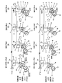
- FIG. 3 is an explanatory diagram of the operation of the variable compression ratio mechanism in the first embodiment, wherein (A) to (D) show the piston position when the vane rotor is in the most retarded state (control phase ⁇ 4), and (A) shows the intake air (Exhaust) Top dead center position, (B) is an intake bottom dead center position, (C) is a compression top dead center position, and (D) is an expansion bottom dead center position. Also, (E) to (H) show the piston position when the vane rotor is in the most advanced angle state (control phase ⁇ 3), (E) is the intake (exhaust) top dead center position, and (F) is the intake bottom dead center.
- FIG. 9 is an operation explanatory diagram of the variable compression ratio mechanism in the second embodiment, wherein (A) to (D) show the piston positions when the vane rotor is in the most advanced angle state (control phase ⁇ 2), and (A) shows Intake (exhaust) top dead center position, (B) is an intake bottom dead center position, (C) is a compression top dead center position, and (D) is an expansion bottom dead center position.
- (E) to (H) show the piston position when the vane rotor is in the most retarded state (control phase ⁇ 3)
- (E) is the intake (exhaust) top dead center position
- (F) is the intake bottom dead center.
- the point position (G) shows the compression top dead center position
- (H) shows the state of the expansion bottom dead center position. It is a characteristic view which shows the height position change of a piston in relation to the rotation angle of the crankshaft in 3rd Embodiment.
- variable compression ratio mechanism in the present embodiment, where (A) to (D) show the piston position when the vane rotor is in the most advanced state (control phase ⁇ 1), and (A) shows the intake air ( (Exhaust) A top dead center position, (B) is an intake bottom dead center position, (C) a compression top dead center position, and (D) is an expansion bottom dead center position. It is the whole schematic figure which shows the link mechanism of the compression ratio variable mechanism of 4th Embodiment.
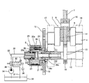
- the internal combustion engine 01 includes a piston 2 that reciprocates in a vertical direction along a cylinder bore 03 formed in the cylinder block 02, and a link mechanism 5 that will be described later of the piston pin 3 and the variable compression ratio mechanism 1 by the vertical movement of the piston 2. And a crankshaft 4 that is rotationally driven via the.
- a space defined between the combustion chamber boundary indicated by a one-dot chain line on the crown surface of the piston 2 in FIG. 1 is an in-cylinder volume (combustion chamber volume).
- an intake valve IV and an exhaust valve EV are provided in the combustion chamber, and are opened and closed by a camshaft (not shown).
- a camshaft not shown
- the intake valve IV and the exhaust valve EV are lifted to the piston 2 side (lower side), as shown in FIG. 1, they approach the piston crown surface.
- the position of the piston 2 at this time is Y.
- the reference position corresponds to a position where both the intake valve IV and the exhaust valve EV are closed without being lifted.
- the piston position Y rises to the yi position of the intake valve IV or the ye position of the exhaust valve EV at a certain crank angle, the piston crown surface and the intake / exhaust valve interfere with each other.
- the variable compression ratio mechanism 1 includes a link mechanism 5 composed of a plurality of links, a piston position changing mechanism 6 that changes the attitude of the link mechanism 5, and the like.
- the link mechanism 5 is connected to the piston 2 via a piston pin 3 and is connected to an upper link 7 as a first link, and to the upper link 7 via a first connection pin 8 so as to be swingable.
- a lower link 10 which is a second link rotatably connected to the crank pin 9 of 4 and an eccentric cam portion of the control shaft 12 which is swingably connected to the lower link 10 via a second connection pin 11.
- the control link 14 is a third link that is rotatably connected to the control unit 13.
- a small-diameter first gear gear 15 that is a driving rotating body is fixed to the front end portion of the crankshaft 4, while the front end portion side of the control shaft 12 is driven to rotate.
- a large-diameter second gear gear 16 is provided, and the first gear gear 15 and the second gear gear 16 mesh with each other, and the rotational force of the crankshaft 4 is transmitted to the control shaft 12 via the piston position changing mechanism 6. It has become so.
- the first gear gear 15 has an outer diameter that is approximately half the outer diameter of the second gear gear 16, so that the rotational speed of the crankshaft 4 is the first gear gear 15 and the second gear gear 16. Is transmitted to the control shaft 12 after being decelerated to a half angular velocity.
- the phase of the control shaft 12 with respect to the second gear gear 16 is changed by the piston position changing mechanism 6, that is, the relative rotational phase with respect to the crankshaft 4 is changed.
- crankshaft 4 and the control shaft 12 are rotatably supported by two common front and rear bearings 17 and 18 provided in the cylinder block. Further, the eccentric cam portion 13 is rotatably connected to a large diameter portion formed at the lower end portion of the control link 14 via a needle bearing 19.
- the piston position changing mechanism 6 has the same structure as the hydraulic (vane type) variable valve mechanism described in, for example, Japanese Patent Application Laid-Open No. 2012-225287 previously filed by the present applicant, and will be briefly described below.
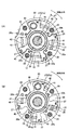
- the piston position changing mechanism 6 is housed in a housing 20 to which the second gear gear 16 is fixed, and in the housing 20 so as to be relatively rotatable, as shown in FIGS. 2 and 3A and 3B.
- a vane rotor 21 fixed to one end of the control shaft 12 and a hydraulic circuit 22 for rotating the vane rotor 21 forward and backward by hydraulic pressure are provided.
- the front end opening of the cylindrical housing body 20a is closed by a disk-shaped front cover 23, and the rear end opening is closed by a disk-shaped rear cover 24. Further, at a position of about 90 ° in the circumferential direction of the inner peripheral surface of the housing main body 20a, shoes 20b that are four partition walls project from the inner side.
- the rear cover 24 is integrally provided at the center position of the second gear gear 16, and the outer peripheral portion thereof is fastened to the housing body 20 a and the front cover 23 by four bolts 25.
- a large-diameter bearing hole 24 a that is supported on the outer periphery of the cylindrical portion of the vane rotor 21 is formed in the center of the rear cover 24 in the axial direction.
- the vane rotor 21 includes a cylindrical rotor 26 having a bolt insertion hole in the center, and four vanes 27 provided integrally at a substantially 90 ° position in the circumferential direction of the outer peripheral surface of the rotor 26.
- a small-diameter cylindrical portion 26a on the front end side is rotatably supported in the center support hole of the front cover 23, while a small-diameter cylindrical portion 26b on the rear end side is rotatably supported in the bearing hole 24a of the rear cover 24.
- the vane rotor 21 is fixed to the front end portion of the control shaft 12 from the axial direction by a fixing bolt 28 inserted through the bolt insertion hole of the rotor 26 from the axial direction.
- Each vane 27 is disposed between the shoes 20b, and a seal member that is slidably in contact with the inner peripheral surface of the housing body 20a in an elongated holding groove formed in the axial direction of each outer surface.
- a leaf spring that presses in the direction of the peripheral surface of the body is fitted and held.
- four advance chambers 40 and retard chambers 41 are respectively formed between both sides of each vane 27 and both sides of each shoe 20b.
- the hydraulic circuit 22 supplies and discharges hydraulic oil pressure to and from each of the advance chambers 40, and supplies and discharges hydraulic oil pressure to and from each retard chamber 41.
- the two hydraulic passages 28 and 29 are connected to a supply passage 30 and a drain passage 31 via an electromagnetic switching valve 32 for switching the passages. ing.
- the supply passage 30 is provided with a one-way oil pump 34 that pumps oil in the oil pan 33, while the downstream end of the drain passage 31 communicates with the oil pan 33.
- the first and second hydraulic passages 28 and 29 are formed inside a passage constituting portion provided on the front cover 23 side, and each one end portion is supported from the small diameter cylindrical portion 26a of the rotor 26 of the passage constituting portion.
- the other end portion is connected to the electromagnetic switching valve 32 while communicating with the rotor 26 via a cylindrical portion 35 inserted and disposed in the hole.
- the first hydraulic passage 28 includes four branch passages (not shown) that communicate with the advance chambers 40, while the second hydraulic passage 29 communicates with the second oil passages that communicate with the retard chambers 41.
- the electromagnetic switching valve 32 is a four-port three-position type, and an internal valve element controls the relative switching between the hydraulic passages 28 and 29, the supply passage 30 and the drain passage 31, and the control. Switching operation is performed by a control signal from the unit 36.
- the vane rotor 21 (control shaft 12) is rotated relative to the crankshaft 4 by selectively supplying hydraulic oil to each advance chamber 40 and each retard chamber 41 by the switching operation of the electromagnetic switching valve 32. Is supposed to change.
- four coil springs 42 that constantly bias the vane rotor 21 in the retard direction are mounted.
- 4 (A) to 4 (D) show a case where the relative rotational phase between the second gear gear 16 and the control shaft 12 is changed.
- the first and second gear gears 15 and 16 are omitted.
- the relative rotational phase can be changed by the relative rotational phase conversion control by the piston position changing mechanism 6 described above, but the second gear gear 16 and the control shaft 12 (eccentric cam portion 13). It can also be performed by relatively changing the mounting relationship.
- the intake (exhaust) top dead center is the exhaust top dead center (intake top dead center), and indicates the position where the piston 2 is highest between the end of the exhaust stroke and the initial intake stroke.
- the position (height) of the piston 2 is near the compression top dead center, it is at a high position.
- the eccentric direction of the eccentric cam portion 13 is higher than the upward direction.
- the position is retarded clockwise by the control phase ⁇ 1 (for example, 137 °).
- FIG. 4B shows a position where the phase of the control shaft 12 (eccentric cam portion 13) is further retarded to ⁇ 2 (for example, 180 °) on the retarded angle side relative to FIG. 4A, that is, the eccentric cam.
- ⁇ 2 for example, 180 °
- the eccentric direction of the portion 13 is near the bottom, and is denoted as a control phase ⁇ 2.
- control phase ⁇ 3 eg, 222 °
- control phase ⁇ 4 eg, 240 °
- phase of the control shaft 12 eccentric cam portion 13
- phase change mechanism 6 actuator position change mechanism
- (B) the operation of the phase change mechanism 6 (piston position change mechanism) that can convert between the control phase ⁇ 3 shown in FIG. 4C and the control phase ⁇ 4 shown in FIG.
- (B) the operation of the phase change mechanism 6 (piston position change mechanism) that can convert between the control phase ⁇ 3 shown in FIG. 4C and the control phase ⁇ 4 shown in FIG.
- (B) the operation of the phase change mechanism 6 (piston position change mechanism) that can convert between the control phase ⁇ 3 shown in FIG. 4C and the control phase ⁇ 4 shown in FIG.
- FIG. 3 is a view of FIG. 2 viewed from the left side, and the rotation direction of the second gear gear 16 is clockwise in FIG.
- FIG. 3A shows the most retarded angle position (corresponding to the control phase ⁇ 4) of the vane rotor 21 of the piston position changing mechanism 6, and
- FIG. 3B shows the most advanced angle position (corresponding to the control phase ⁇ 3).
- both the most retarded angle and the most advanced angle position of the vane 27 (27a) with the maximum widening are in contact with one side surface and the other side surface of each adjacent shoe 20b, and stoppers (retard angle side stopper, advance angle side stopper). ).
- the vane rotor 21 is mechanically stabilized in the vicinity of the most retarded position as shown in FIG. 3A by the spring force of each coil spring 42. That is, the default position is the most retarded position.
- a desired conversion angle ⁇ T is obtained by conversion between the control phase ⁇ 3 and the control phase ⁇ 4. (18 °) can be realized.
- the attachment position of the vane rotor 21 and the control shaft 12 is set so that the aforementioned most retarded angle position (default position) coincides with the control phase ⁇ 4 shown in FIG. Phase conversion between C) and FIG. 4D (control phase ⁇ 3 ⁇ control phase ⁇ 4) can be realized.
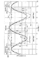
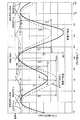
- Fig. 5 shows the change characteristics of the piston position.
- the crank angle X is 0 °
- the crank pin 9 is located directly above, and the intake (exhaust) top dead center of the piston 2 is located in the vicinity thereof.
- the exhaust valve EV When the crank angle X starts to rotate clockwise from 0 °, the exhaust valve EV is completely closed as shown in the exhaust valve lift curve (ye), and the intake valve IV that has started to open from 0 ° has been started.
- the intake valve lift curve (yi) further increases the lift and sucks fresh air (or mixture) from the intake port.
- the intake bottom dead center is reached in the vicinity of the crank angle X of 180 °, and the intake valve is closed in this vicinity.
- the intake stroke is from the intake top dead center to the intake bottom dead center.
- the intake valve IV is completely closed and the in-cylinder air-fuel mixture is compressed, near the position where the crank angle X becomes 360 ° (the crankpin 9 is again directly above). And it becomes compression top dead center.
- the range from the intake bottom dead center to the compression top dead center is referred to as a compression stroke.
- spark ignition or compression ignition
- combustion is started, and the combustion pressure pushes down the piston 2, and an expansion bottom dead center is reached when the crank angle X is around 540 °.
- an expansion stroke the process from the compression top dead center to the expansion bottom dead center is referred to as an expansion stroke.
- the exhaust valve EV starts to open, and as the piston 2 rises again, combustion gas (exhaust gas) is discharged from the exhaust port, and again near the top dead center of the intake (exhaust).
- the range from the expansion bottom dead center to the intake (exhaust) top dead center is called the exhaust stroke.
- the operation as a four-cycle engine is performed, and the operation is periodic with a crank angle (X) of 720 ° as one cycle.
- the solid line indicates the piston position characteristic ( ⁇ 3 characteristic) at the control phase ⁇ 3 in FIG. 4C
- the broken line indicates the piston position characteristic ( ⁇ 4 characteristic) at the control phase ⁇ 4 in FIG. Yes.
- the piston position at the compression top dead center is substantially the same (Y0)
- the intake bottom dead center position is different in both characteristics. That is, the cylinder internal volume (combustion chamber volume) V at the compression top dead center is determined by the piston position (Y0) at the compression top dead center, so that the cylinder internal volume V0 is substantially the same.
- the cylinder volume V0 is surrounded by the shape of the combustion chamber on the cylinder head side, the shape of the crown surface 2a of the piston 2, the inner diameter of the cylinder block 02, the inner diameter of the head gasket (not shown), etc. at the compression top dead center.
- the piston position of the intake bottom dead center is YC3, and the length from the compression top dead center to the compression top dead center (compression stroke) is LC3.
- the position is YE3, and the length from the compression top dead center (expansion stroke) to the position is LE3.
- the piston position at the intake bottom dead center is YC3 described above, the length from the intake (exhaust) top dead center (intake stroke) is LI3, and the piston position at the expansion bottom dead center is described above.
- the length from the intake (exhaust) top dead center (exhaust stroke) to LO3 is LO3.
- the piston position of the intake bottom dead center is YC4, and the length from that to the compression top dead center (compression stroke) is LC4.
- the piston position of the point is YE4, and the length (expansion stroke) from the compression top dead center to it is LE4.
- the piston position at the intake bottom dead center is the aforementioned YC4, and the length from the intake (exhaust) top dead center (intake stroke) is LI4.
- the piston position at the expansion bottom dead center is the aforementioned position.
- the length from the intake (exhaust) top dead center (exhaust stroke) is LO4.
- the intake (exhaust) top dead center and the exhaust (intake) top dead center mean the same point, and indicate the top dead center of the piston when shifting from the exhaust stroke to the intake stroke. Therefore, it may be simply referred to as intake top dead center or exhaust top dead center.
- FIG. 5 is the same in FIG. 7 of the second embodiment and FIG. 9 of the third embodiment, and thus detailed description thereof is omitted in FIGS.
- VE3 is the cylinder volume at the expansion bottom dead center.
- FIGS. 6A to 6D show changes in the mechanism posture when the crank angle is changed at the control phase ⁇ 4 (the most retarded angle default position of the vane rotor 21, for example, 240 °).
- FIGS. Shows a change in the mechanism posture when the crank angle at the control phase ⁇ 3 (the most advanced position of the vane rotor 21, for example, 222 °) is changed.
- (A) and (E) in FIG. 6 are postures at the intake (exhaust) top dead center
- (B) and (F) are postures at the intake bottom dead center
- (C) and (G) are compression.
- (D) and (H) show postures at the inflated bottom dead center, respectively.
- the difference in the piston position change characteristic between the control phase ⁇ 3 and the control phase ⁇ 4 shown in FIG. 5 is generated by the difference in the link posture based on the difference in the eccentric phase of the eccentric cam portion 13 shown in FIG.
- the position of the piston 2 in the control phase ⁇ 3 and the control phase ⁇ 4 is substantially the same as described above, but this is due to the following reason. That is, as shown in the compression top dead center postures shown in FIGS. 6C and 6G, the crank pin 9, the first connecting pin 8, and the piston pin 3 are arranged substantially in a straight line in both the control phase ⁇ 3 and the control phase ⁇ 4. This is because, by this arrangement, even if the first connecting pin 8 is rotated by the rotation of the lower link 10, the position change of the piston pin 2 is slightly suppressed.
- the piston position (Y03 in FIG. 5) of the compression top dead center of the control phase ⁇ 3 and the compression top dead center piston position (Y04 of FIG. 5) of the control phase ⁇ 4 are substantially the same position, which is the above-mentioned compression top dead center. This is the dead center piston position (Y0).
- the vane rotor 21 of the piston position changing mechanism 6 is pressed by the spring force of each coil spring 42 to the most retarded angle position (counterclockwise direction) shown in FIG.
- the control phase is the aforementioned control phase ⁇ 4.
- the characteristic of the control phase ⁇ 4 that is the most retarded position of the vane rotor 21 is shown in advance (broken line in FIG. 5). Obtained from. Further, this position can be maintained even when the electrical system of the electromagnetic switching valve 32 of the piston position changing mechanism 6 has a failure such as disconnection. Even in this case, the above-mentioned exhaust emission reduction effect can be obtained, so-called mechanical fail safe. It can also have an effect.
- the first effect of the exhaust emission reduction effect at the time of cold engine start due to this characteristic is that, since the mechanical expansion ratio E4 is small, the temperature of exhaust gas discharged from the internal combustion engine is increased by the amount of expansion work reduced. Therefore, warming up of the downstream catalyst is promoted, and the emission conversion rate is improved.
- the relative ratio D4 is a small value less than 1, which means that the smaller this is, the smaller the mechanical expansion ratio and the larger the mechanical compression ratio. It can be regarded as an index indicating good performance.
- the fuel consumption deteriorates in the state where the mechanical compression ratio C4, the mechanical expansion ratio E4, and the relative ratio D4 remain unchanged. Because the mechanical expansion ratio E4 is low, the expansion work by the piston 2 is reduced, and the mechanical compression ratio C4 is high, so that the temperature at the compression top dead center becomes excessively high after warm-up, so-called cooling loss occurs. As a result, the fuel consumption deteriorates due to these losses.
- the vane rotor 21 is converted to the most advanced angle position by the control hydraulic pressure from the electromagnetic switching valve 32 of the piston position changing mechanism 6 and switched to the control phase ⁇ 3 (characteristic of the solid line in FIG. 5). It ’s good.
- the standard mechanical expansion ratio E3 and the standard mechanical compression ratio C3 are restored, and the relative ratio D3 is approximately 1, which is equivalent to the normal piston position change characteristic.
- the occurrence of abnormal combustion can be suppressed.
- the vane rotor 21 is changed to the retard side as the temperature becomes lower (closer to the control phase ⁇ 4), and the engine temperature becomes higher.
- the vane rotor 21 is changed to the advance side (closer to the control phase ⁇ 3), the exhaust emission performance and the fuel consumption performance can be appropriately balanced for each temperature change. For example, fuel consumption deterioration can be suppressed as much as possible while suppressing the emission to a sufficiently low predetermined value.
- the position change characteristic of the piston 2 is a periodic operation with a crank angle of 720 ° as a cycle, and the top dead center is 2 when the crank angle is around 0 ° and around 360 °. Appears.
- the top dead center near the crank angle of 360 ° (Y0 mentioned above) is the compression top dead center where both the intake valve IV and the exhaust valve EV are completely closed, and each top near the crank angle of 0 °.
- the dead point (Y'03, Y'04) is an intake (exhaust) top dead center at which the exhaust valve EV closes and the operation of the intake valve IV starts.
- This intake (exhaust) top dead center piston position (Y'03, Y'04) is lower than the compression top dead center piston position (Y0).
- the crank pin 9, the first connecting pin 8, and the piston pin 3 are both in the control phase ⁇ 3 and the control phase ⁇ 4. It is not a straight line but is bent in a reverse “ ⁇ ” shape, and this arrangement makes the piston position lower than the aforementioned piston position (Y0), and the control phase ⁇ 3 and control phase ⁇ 4 are controlled.
- the piston positions (Y'03, Y'04) at the intake (exhaust) top dead center are lower than the piston positions (Y0) at the compression top dead center. This is extremely advantageous against interference between the valve IV and the exhaust valve EV.
- the piston positions (Y'03, Y'04) are low.
- the crown surface position (Y) of the piston 2 is sufficiently separated downward so that interference is difficult.
- the intake valve IV and the exhaust valve EV are likely to cause abnormal movement such as jump and bounce.
- yi and ye are slightly lowered, but the intake valve IV and the exhaust valve EV are slightly lowered.
- a variable valve mechanism capable of increasing and changing the opening / closing phase control of the intake valve IV and the exhaust valve EV and the lift amount itself, which has been widespread in recent years, is installed, the mechanical mechanism of the intake valve IV, the exhaust valve EV, and the piston Interference is likely to occur.
- the yi characteristic and the ye characteristic are shifted in the horizontal axis (crank angle) direction, so the distance from Y is partially approached, or in the increase control of the lift amount itself, the yi characteristic and the ye characteristic itself are downward. Since it is shifted, the distance from Y approaches. Even in such a case, mechanical interference between the intake valve IV, the exhaust valve EV, and the piston can be effectively prevented by using the variable compression ratio mechanism of the present embodiment.
- the high piston position (Y0) is the intake (exhaust) top dead center.
- the interference with the intake valve lift curve (yi) and the exhaust valve lift curve (ye) shown by the broken line in FIG. 5 is reduced, and when the intake valve IV or exhaust valve EV moves abnormally, such as jump or bounce.
- the problem of interference with the piston occurs.
- the crank angle at which interference easily occurs is not the intake (exhaust) top dead center itself, but the distance between the ye of the exhaust valve EV and the piston crown surface position Y immediately before the intake (exhaust) top dead center.
- the piston positions (Y'03, Y'04) at the intake (exhaust) top dead center are lower than the piston positions (Y0) at the compression top dead center. This produces an effect of increasing the amount of exhaust gas.
- the piston position at the top dead center of the intake (exhaust) is increased to the piston position at the top dead center of the compression, the piston rises high from the end of the exhaust stroke to the beginning of the intake stroke, so the volume of the combustion chamber decreases, The amount of combustion gas remaining in the cylinder is reduced.
- the piston position at the intake (exhaust) top dead center is set to a position lower than the compression top dead center, so that the combustion chamber volume increases from the end of the exhaust stroke to the beginning of the intake stroke, resulting in a high temperature.
- the amount of residual exhaust gas increases, the temperature in the combustion chamber can be kept high, and the internal EGR effect can be sufficiently obtained.
- the temperature of the combustion chamber and in-cylinder gas can be increased by a large amount of residual exhaust gas, so that the effect of reducing exhaust emission is enhanced.
- the piston position is a high piston position (Y0) at the compression top dead center
- the mechanical compression ratio C or the mechanical expansion ratio E can be set large, so that various engine performances can be sufficiently enhanced.
- the intake valve IV and the exhaust valve EV do not operate (lift increases) at the compression top dead center, and the closed state continues.
- the problem of interference with EV does not occur in principle.
- the piston positions at the top dead center of the intake (exhaust) from the lift position (yi max) where the lift amount of the intake valve IV is maximum and the lift position (ye max) where the lift amount of the exhaust valve EV is maximum. If Y′03 and Y′04) are set low, even if a failure occurs in the above-described opening / closing phase control of the intake / exhaust valve, the interference between the intake / exhaust valve and the piston is prevented regardless of the phase. The special effect of being able to prevent can be acquired.
- each piston position (Y'03, Y'04) at the intake (exhaust) top dead center is set to a position lower than the piston position (Y0) at the compression top dead center, at the end of the exhaust stroke or at the beginning of the intake stroke
- the combustion chamber volume increases, the amount of high-temperature residual exhaust gas increases in the cylinder, and the temperature of the combustion chamber and cylinder gas can be increased, so that the so-called internal EGR effect can be sufficiently obtained.
- the temperature of the combustion chamber and the intake air-fuel mixture can be increased by a large amount of residual exhaust gas, so that the effect of reducing exhaust emission is enhanced.
- a vane-type piston position changing mechanism 6 is installed on the second gear gear 16 having a body diameter on the side to be decelerated with respect to the first gear gear 15. Yes.
- the piston position changing mechanism 6 is installed in the first gear gear 15 having a small diameter on the crank side, it becomes possible to set the vane diameter or the like large, and the vane conversion power can be increased. It is also possible to improve responsiveness and increase load resistance.
- the piston position at the intake (exhaust) top dead center is set lower than the piston position at the compression top dead center by the variable compression ratio mechanism.
- the intake / exhaust valve can be prevented from interfering with each other, or the internal EGR effect can be sufficiently obtained.
- Example 1 the relative phase between the vane and the control shaft was controlled between the control phase ⁇ 3 and the control phase ⁇ 4.
- Example 2 however, the vane and the control shaft were controlled. The difference is that the relative phase to the shaft is controlled between the control phase ⁇ 2 and the control phase ⁇ 3.
- the vane conversion angle is larger than that of the first embodiment, but the vane conversion angle can be increased by thinning the vicinity of the stopper portion of the housing or the side surface of the vane. Even if the number of vanes is reduced from 4 to 3, the conversion angle can be increased. Then, the vane and control shaft mounting phases may be set so that the most retarded angle position (default position) where the retarded stopper and the vane contact each other coincides with the position ⁇ 3 in FIG.
- the vane-type piston position changing mechanism 6 since the vane-type piston position changing mechanism 6 is installed on the second gear gear 16 on the speed-reduced side, the vane diameter and the like can be set appropriately large. Thereby, the vane conversion power by the piston position changing mechanism 6 can be ensured, and the decrease in conversion response and the decrease in the vane holding ability can be suppressed.
- FIG. 7 shows the piston position change characteristic, and the solid line shows the same characteristic ( ⁇ 3 characteristic) as the control phase ⁇ 3 of FIG. 4C of Example 1, but in this embodiment, the most retarded (default) position of the vane rotor 21 It becomes the characteristic in. 7 is the characteristic ( ⁇ 2 characteristic) of the control phase ⁇ 2 shown in FIG. 4B, which is the characteristic at the most advanced angle position of the vane rotor 21 of the present embodiment.
- the position (Y02) of the piston at the compression top dead center is substantially the same as the above-mentioned Y0, but the intake bottom dead center position and the expansion bottom dead center position are different from each other in the control phase ⁇ 3. Is different.
- the difference in the piston position change characteristics between the control phase ⁇ 3 and the control phase ⁇ 2 shown in FIG. 7 is generated by the difference in the link posture due to the difference in the eccentric rotation direction of the eccentric cam portion 13 shown in FIG.
- the vane rotor 21 of the piston position changing mechanism 6 is converted to the most advanced position by the control hydraulic pressure from the electromagnetic switching valve 32 and becomes the control phase ⁇ 2, in which the mechanical compression ratio C2 is small,
- the mechanical expansion ratio E2 is large.
- the mechanical expansion ratio E2 is large, the work (expansion work) performed when the combustion pressure pushes down the piston can be increased, and thereby, for example, the fuel efficiency can be improved in the partial load operation region.
- a normal piston position change characteristic such as the control phase ⁇ 3 is used when the engine is cold.
- the rotational phase of the vane rotor 21 of the piston position changing mechanism 6 is controlled, and the temperature becomes closer to the control phase ⁇ 3 as the temperature becomes lower.
- the control is performed so as to approach the control phase ⁇ 2.
- the control phase ⁇ 2 and the control phase ⁇ 3 are periodically operated with a crank angle of 720 °, and the top dead center is a crank angle near 0 ° (720 °). It appears twice around 360 °.
- Each top dead center (Y02, Y03) in the vicinity of a crank angle of 360 ° is a compression top dead center in which both the intake valve and the exhaust valve are completely closed, and is substantially in the same position as Y0 described above.
- the top dead center near the crank angle of 0 ° is the intake (exhaust) top dead center at which the exhaust valve is closed and the operation of the intake valve is started, and each piston position is Y′02, Y'03.
- the piston positions (Y'02, Y'03) at the intake (exhaust) top dead center are lower than the piston positions (Y0) at the compression top dead center.
- the crank pin 9, the first connecting pin 8, and the piston pin 3 are aligned with each other in both the control phase ⁇ 2 and the control phase ⁇ 3. This is because the piston is bent in the shape of an inverted " ⁇ ", and this arrangement lowers the piston position from the piston position (Y0) at the compression top dead center.
- the piston (Y'02, Y'03) at the intake (exhaust) top dead center is lower than the compression top dead center (Y0) and substantially at the same position.
- the control phase ⁇ 2 with respect to the intake valve lift position (yi) of the intake valve IV and the exhaust valve lift position (ye) of the exhaust valve EV, as viewed at the crank angle near the top dead center of the intake (exhaust) in FIG.
- the crown surface position of the piston 2 is sufficiently separated downward in the control phase ⁇ 3 and is less likely to interfere.
- the intake valve IV and the exhaust valve EV are likely to cause abnormal movement such as jump and bounce.
- the interference can be sufficiently prevented as in the first embodiment.
- a variable valve mechanism capable of increasing and changing the opening / closing phase control of the intake valve IV and the exhaust valve EV and the lift amount itself, which has been widespread in recent years, is installed, the mechanical mechanism of the intake valve IV, the exhaust valve EV, and the piston Interference is likely to occur. Even in such a case, mechanical interference among the intake valve IV, the exhaust valve EV, and the piston can be effectively prevented by using the variable compression ratio mechanism of the present embodiment. It is the same.
- the high piston position (Y0) is the intake (exhaust) top dead center.
- the piston position, and the interference margin between the intake valve lift position (yi) and the exhaust valve lift position (ye) at each crank angle indicated by the broken line in FIG. 7 and the piston crown surface position Y becomes small, and intake valves such as jumps and bounces There is a problem that the piston and the intake / exhaust valve easily interfere with each other when the IV or the exhaust valve EV moves abnormally.
- the piston position of the intake (exhaust) top dead center is set to a position lower than the compression top dead center, so that the combustion chamber volume increases from the end of the exhaust stroke to the beginning of the intake stroke, and the cylinder
- the amount of high-temperature residual exhaust gas in the interior increases, and the temperature of the combustion chamber and in-cylinder gas can be maintained high, so that the internal EGR effect can be sufficiently obtained.
- the temperature of the combustion chamber and the intake air-fuel mixture is low, the temperature can be increased by a large amount of residual exhaust gas, so that the effect of reducing exhaust emission is enhanced.
- the internal EGR effect improves combustion in the partial load region and also reduces the pump loss, thereby further improving the fuel efficiency.
- the mechanical compression ratio C or the mechanical expansion ratio E can be set large, so that various engine performances can be sufficiently enhanced.
- the fuel efficiency effect can be further enhanced by a large mechanical expansion ratio E in the partial load region.
- the intake valve IV and the exhaust valve EV do not operate (lift increases) at the compression top dead center, and the closed state continues. The problem of interference with EV does not occur in principle.
- the exhaust valve EV is closed and the intake valve IV is opened in this vicinity, so that the piston position is as high as the compression top dead center piston position (Y0). If in the position, mechanical interference between the intake valve IV and the exhaust valve EV and the piston may occur. As described above, the piston position (Y′02, Y ′) at the top dead center of the intake (exhaust). 03) is at a position lower than the compression top dead center piston position (Y0), so that such mechanical interference can be avoided.
- the piston position at the intake (exhaust) top dead center is set to a position lower than the compression top dead center, the volume of the combustion chamber in the exhaust stroke increases and the amount of high-temperature residual exhaust gas increases.
- the temperature can be maintained high and the internal EGR effect can be sufficiently obtained.
- the temperature of the combustion chamber can be maintained high by a large amount of residual exhaust gas, so that the effect of reducing exhaust emission becomes high, and this internal EGR even after warm-up. Due to the effect, combustion is improved in the partial load region, and the pump loss is also reduced thereby, so that the fuel efficiency effect can be further enhanced.
- the piston position (Y′02, Y′03) at the top dead center of the intake (exhaust) is substantially the same in the control phase ⁇ 2 and the control phase ⁇ 3.
- the control phase ⁇ 2 and the control phase ⁇ 3 have substantially the same interference margin.
- the control angle range within the range of the control phase ⁇ 2 and the control phase ⁇ 3 has substantially the same interference margin. Therefore, the interference margin is almost the same over the variable control range.
- the controller fails and the piston stroke control ( ⁇ angle control) as in the present embodiment is abnormal, the interference margin is almost the same regardless of the control position. For this reason, the possibility of mechanical interference between the piston, the intake valve, and the exhaust valve can be avoided even in the event of an abnormality such as a controller failure. In addition, even when an overshoot (overspeed) occurs due to a shift error of the driver, the occurrence of mechanical interference between the piston, the intake valve, and the exhaust valve can be similarly suppressed.
- Example 1 the relative phase between the vane and the control shaft is controlled between the control phase ⁇ 3 and the control phase ⁇ 4, and in Example 2, the control phase ⁇ 2 and The control is performed during the control phase ⁇ 3, but the third embodiment is different in that the relative phase between the vane and the control shaft is controlled between the control phase ⁇ 1 and the control phase ⁇ 4.
- the conversion angle may be increased by reducing the number of vanes 27 from four to two, in this embodiment, as a piston position changing mechanism, Japanese Patent Application Laid-Open No. 2012-197755 (Patent Document 2) A motorized one as described in 2012-180816 (Patent Document 3) is used.
- the mechanism is configured to convert the phase between the camshaft and the timing sprocket via the speed reduction mechanism by the rotation of the electric motor.
- the control shaft 12 is used instead of the camshaft
- the second gear gear 16 is used instead of the timing sprocket.
- this sets the most advanced angle phase of the output shaft of the electric piston position changing mechanism to the control phase ⁇ 1 and the most retarded angle phase to the control phase ⁇ 4. Further, as in the first and second embodiments, an urging means for urging the control shaft 12 in the retarding direction is also provided.
- FIG. 9 shows the piston position change characteristic
- the broken line shows the characteristic (maximum retardation angle) at the control phase ⁇ 4, which is the same characteristic as the control phase ⁇ 4 of FIG. 5 of the first embodiment
- the solid line is the control phase.
- the characteristic (the most advanced angle) at the phase ⁇ 1 corresponds to the control phase ⁇ 1 in FIG.
- FIGS. 10A to 10D are diagrams showing a change in the mechanism posture at the control phase ⁇ 1, as in FIGS. 6 and 8, (A) is an intake (exhaust) top dead center, and (B) is an intake bottom dead center. A point, (C) shows a compression top dead center, and (D) shows each posture at an expansion bottom dead center.
- the eccentric rotation direction ⁇ C1 of the eccentric cam portion 13 in the intake bottom dead center posture is substantially opposite to the direction of the control link 14. For this reason, the control link 14 and the second connecting pin 11 are pulled down to the lower left direction to the maximum extent, and the lower link 10 changes to a maximum phase in the counterclockwise direction around the crank pin 9, and accordingly, the first connecting position.
- the pin 8 moves upward almost as much as possible, so that the piston 2 is pushed upward almost as much as possible by the upper link 7.
- LC1 is sufficiently small and almost maximally small, and the relationship LC1 ⁇ LC2 ⁇ LC3 ⁇ LC4 is established.
- the direction is substantially the same as the direction of the control link 14.
- the eccentric cam portion 13 is converted to the most advanced position by the electric piston position changing mechanism, and the mechanical compression ratio C1 in the control phase ⁇ 1 is sufficient.
- the mechanical expansion ratio E1 is controlled to a sufficiently large and almost maximum characteristic.
- the mechanical expansion ratio E1 is almost as large as possible, the work performed by the combustion pressure pushing down the piston can be increased almost as much as possible.
- abnormal combustion such as knocking at a high engine load can be sufficiently suppressed by the substantially minimum mechanical compression ratio C1, and the fuel efficiency can be sufficiently improved by the almost maximum mechanical expansion ratio E1.
- the exhaust gas temperature high temperature exhaust gas at high load
- the thermal deterioration of the catalyst can be sufficiently suppressed.
- the fuel efficiency is sufficiently improved during partial load operation after completion of warm-up, and the exhaust gas temperature is further sufficiently decreased at high loads to reduce the catalyst. It can prevent thermal degradation.
- the relative ratio D1 is a sufficiently large value exceeding 1, and the larger this is, the higher the mechanical expansion ratio is. This means that the mechanical compression ratio is relatively low, and can be regarded as an index indicating the height of the above-described effect in fuel efficiency.
- the engine when the engine is cold, it is converted into a piston position change characteristic in which the mechanical compression ratio C is large and the mechanical expansion ratio E is small as in the control phase ⁇ 4.
- the relative ratio D4 is a value lower than 1, meaning that the smaller this is, the smaller the expansion ratio is, and the larger the compression ratio is, and this is regarded as an index indicating the good exhaust emission performance. This can be done as described above.
- the fuel efficiency after warm-up can be improved to the maximum extent, and the exhaust emission during cold-start can be reduced as in the first embodiment.
- the relative ratio is increased to D1 greater than 1 to increase the fuel efficiency, and when cold, the relative ratio is lowered to D4 smaller than 1 to improve exhaust emissions during cold.
- the output shaft phase of the electric piston position changing mechanism (phase of the eccentric cam portion 13) is controlled to a high conversion angle.
- the control is performed so that the temperature becomes closer to the control phase ⁇ 4 as the temperature becomes lower, and closer to the control phase ⁇ 1 as the temperature becomes higher.
- the knock resistance can be improved by reducing the mechanical compression ratio, but as the mechanical compression ratio is reduced, the suction stroke ( ⁇ compression stroke) tends to decrease and the filling efficiency decreases. It may be possible to do so.
- the mechanical compression ratio is set so that the transient torque is maximized quickly during acceleration transients. In some cases, it is required to appropriately control the correction.
- the electric piston position changing mechanism is used as described above. Therefore, a high response conversion can be performed regardless of the engine oil pressure or the engine temperature, so that the effect of improving the transient torque is sufficiently obtained. Obtainable.
- the electric piston position changing mechanism can quickly change to a high mechanical expansion ratio, so that the fuel efficiency effect is also quick. It will be obtained.
- the piston position change characteristic is obtained by performing a periodic operation with a crank angle of 720 ° as a cycle in both the control phase ⁇ 1 and the control phase ⁇ 4 as described above, and the top dead center.
- the crank angle appears twice at around 0 ° (720 °) and around 360 °.
- the top dead center near a crank angle of 360 ° is a compression top dead center in which both the intake valve and the exhaust valve are completely closed, and the piston position of the compression top dead center is substantially the same as the above-described Y0.
- the top dead center near the crank angle of 0 ° is the piston position (Y′01, Y′04) of the intake (exhaust) top dead center at which the exhaust valve is closed and the operation of the intake valve is started.
- the piston positions (Y′01, Y′04) at the intake (exhaust) top dead center are lower than the piston positions (Y0) at the compression top dead center.
- the crank pin 9, the first connecting pin 8, and the piston pin 3 are used for both the control phase ⁇ 1 and the control phase ⁇ 4. Is not a straight line but is bent in a reverse “ ⁇ ” shape, and this arrangement lowers the piston position from the compression top dead center piston position (Y0).
- the eccentric direction of the eccentric cam portion 13 with respect to the control link 14 is different between the control phase ⁇ 1 and the control phase ⁇ 4.
- the opening angle itself is larger in the control phase ⁇ 1 and close to 180 °. Therefore, the intake (exhaust) top dead center piston position in control phase ⁇ 1 (Y′01, decreased by ⁇ 1) is slightly higher than the piston position in control phase ⁇ 4 (Y′04, decreased by ⁇ 4). However, it is sufficiently lower than the piston position (Y0) for compression top dead.
- the intake valve IV and the exhaust valve EV are likely to cause abnormal movement such as jump and bounce.
- the intake valve IV, the exhaust valve EV and the piston interfere with each other. Can be sufficiently prevented.
- a variable valve mechanism capable of increasing and changing the opening / closing phase control of the intake valve IV and the exhaust valve EV and the lift amount itself, which has been widespread in recent years, is installed, the mechanical mechanism of the intake valve IV, the exhaust valve EV, and the piston Interference is likely to occur. Even in such a case, mechanical interference between the intake valve IV, the exhaust valve EV, and the piston can be effectively prevented by using the variable compression ratio mechanism of the present embodiment. Moreover, these effects can be obtained in the entire control range.
- the piston position at the intake (exhaust) top dead center is set to a position lower than the piston position at the compression top dead center, so that the volume of the combustion chamber in the exhaust stroke increases and the high-temperature residual exhaust gas The amount increases, the temperature of the combustion chamber can be kept high, and the internal EGR effect can be sufficiently obtained. For example, in an operation state in which the temperature of the combustion chamber is low, the temperature of the combustion chamber can be maintained high by a large amount of residual exhaust gas, so that the effect of reducing exhaust emission is enhanced.
- the piston position of the intake (exhaust) top dead center with the ultra-low mechanical compression ratio and ultra-high expansion ratio at the control phase ⁇ 1 (decreased by ⁇ 1 at Y′01) is as described above. Although it is lower than the compression top dead center piston position (Y0), it is the highest position in the entire control range. Thereby, the following effects are acquired.
- the ultra-low mechanical compression ratio and the ultra-high expansion ratio are high, and the fuel efficiency is high, but there is a tendency that the intake stroke is reduced along with the reduction of the compression stroke LC1. is there. Therefore, there is a problem that the intake air amount is not limited, and it is difficult to expand the control region of the control phase ⁇ 1 with good fuel efficiency to the high load (high torque) side.
- the piston position (Y'01) at the top dead center of the intake (exhaust) is set slightly higher, so that the intake stroke increases slightly with LI1, and thus a control phase with good fuel efficiency.
- the control range of ⁇ 1 can be expanded to the high load (high torque) side.
- the control by the control phase ⁇ 1 is originally not used in the extremely high rotation region due to the restriction of the intake air intake amount described above, so the piston position (Y'01) of the intake (exhaust) top dead center is set to the compression top dead center.
- the mechanical interference between the intake valve IV, the exhaust valve EV and the piston can be effectively prevented without being extremely lowered from the piston position (Y0).
- the link mechanism 5 includes an upper link 7 connected to the piston 2 via the piston pin 3, a swingable connection to the upper link 7 via the first connection pin 8, and the control shaft 12.
- a control link 14 that is swingably connected to the eccentric cam portion 13, and is swingably connected to the control link 14 via the second connecting pin 11 and is rotatably connected to the crankpin 9 of the crankshaft 4.
- a lower link 10 that is, the link mechanism 5 includes an upper link 7 connected to the piston 2 via the piston pin 3, a swingable connection to the upper link 7 via the first connection pin 8, and the control shaft 12.
- a control link 14 that is swingably connected to the eccentric cam portion 13, and is swingably connected to the control link 14 via the second connecting pin 11 and is rotatably connected to the crankpin 9 of the crankshaft 4.
- the rotation of the crankshaft 4 is transmitted to the second gear gear 16 (control shaft 12) by being reduced to a half angular velocity via the first gear gear 15 as in the first to third embodiments.
- the second gear gear 16 and the control shaft 12 can change the relative rotational phase by the piston position changing mechanism 6 similar to that of the first to third embodiments.
- FIG. 11 shows the posture of the piston 2 in the vicinity of the bottom dead center of the intake (exhaust), that is, the position where the crank pin 9 faces directly upward.
- the eccentric rotation direction of the eccentric cam portion 13 is substantially right above, and the crank pin 9, the second connecting pin 11, and the piston pin 3 are substantially straight and directly upward.
- the piston position (Y′0) at the intake (exhaust) top dead center is lower than the piston position (Y0) at the compression top dead center as in the first to third embodiments. It can be set, and mechanical interference of the intake valve IV, the exhaust valve EV and the piston can be effectively prevented from the end of the exhaust stroke to the beginning of the intake stroke while ensuring a high compression ratio or expansion ratio. As in the first to third embodiments, both the mechanical compression ratio and the mechanical expansion ratio can be changed by performing phase conversion by the piston position changing mechanism.
- the piston position (Y′0) at the intake (exhaust) top dead center can be set lower than the piston position (Y0) at the compression top dead center, and the internal EGR effect is similarly achieved. Can be increased.
- the present invention is not limited to the configuration of each of the above-described embodiments.
- a single-cylinder internal combustion engine is shown, but a multi-cylinder such as 2-cylinder, 3-cylinder, or 4-cylinder is used. It may be applied to an internal combustion engine.
- the piston operating characteristics of all the cylinders can be changed by a single or a plurality of piston position changing mechanisms, so that all the cylinders can be controlled to a desired mechanical compression ratio and mechanical expansion ratio.
- the piston position at the intake (exhaust) top dead center is set lower than the piston position at the compression top dead center by the variable compression ratio mechanism. According to this, when the piston position at the compression top dead center is increased in order to obtain a high mechanical compression ratio, the piston position at the intake (exhaust) top dead center is set low in the exhaust stroke, so that The exhaust valve can be prevented from interfering, or the internal EGR effect can be sufficiently obtained.
- two piston position changing mechanisms are shown as the transmission mechanism from the piston to the crankshaft.
- the configuration of this mechanism may be selected as appropriate without departing from the gist of the present invention, and is particularly limited. Not a translation.
- an example of a pair of first and second gear gears 15 and 16 has been shown as a speed reduction mechanism that decelerates the rotation of the crankshaft 4 to a half angular velocity and transmits it to the eccentric cam portion 13 (control shaft 12). It is not limited to.
- the rotation direction of the crankshaft 4 and the rotation direction of the eccentric cam portion 13 are opposite to each other, but may be the same direction.
- the rotation of the first gear gear 15 on the crankshaft 4 side is decelerated to a half angular velocity via a timing belt (timing chain) and transmitted to the second gear gear 16 on the eccentric cam portion 13 side.
- the rotation direction of the crankshaft 4 and the rotation direction of the eccentric cam portion 13 are the same direction, and the piston position change characteristic (vertical axis) with respect to the rotation angle (horizontal axis) of the crankshaft 4 is reversed left and right. Can be realized.
- the configuration is not particularly limited as long as it does not depart from the gist of the present invention.
- the piston position at the intake (exhaust) top dead center is set lower than the piston position at the compression top dead center by the variable compression ratio mechanism.
- the intake / exhaust valve can be prevented from interfering with each other, or the internal EGR effect can be sufficiently obtained.
- a compression ratio adjusting device for an internal combustion engine having a variable compression ratio mechanism capable of changing a mechanical compression ratio and a mechanical expansion ratio by changing a stroke position of a piston in a four-cycle internal combustion engine.
- the variable compression ratio mechanism is characterized in that the piston position at the intake (exhaust) top dead center is set at substantially the same position over the entire variable range of the variable compression ratio mechanism.
- a compression ratio adjusting device for an internal combustion engine having a variable compression ratio mechanism capable of changing a mechanical compression ratio and a mechanical expansion ratio by changing a stroke position of a piston in a four-cycle internal combustion engine.
- the variable compression ratio mechanism includes a first link having one end connected to a piston via a piston pin, and a first link that is rotatably connected to the other end of the first link via a first connecting pin.
- a second link rotatably connected to the pin, a control shaft that rotates at an angular velocity of 1 ⁇ 2 with respect to the crankshaft, an eccentric shaft portion that is provided on the control shaft and is eccentric with respect to the rotational axis of the control shaft;
- a third link having one end connected to the second link via a second connecting pin and the other end rotatably connected to the eccentric shaft portion; and a control shaft
- a relative displacement mechanism capable of changing the eccentric direction of the eccentric shaft portion with respect to the shaft center, and set so that the shaft center of the eccentric shaft portion at the compression top dead center is opposite to the second connecting pin from the shaft center of the control shaft.
- the center of the eccentric shaft at the exhaust top dead center is set to be on the second connecting pin side with respect to the axis of the control shaft, and the variable compression ratio mechanism is Sometimes, set the piston position at the intake bottom dead center of the piston to the same position as the piston position at the expansion bottom dead center, or set the piston position at the intake bottom dead center lower than the piston position at the expansion bottom dead center. It is characterized by.
- a compression ratio adjusting device for an internal combustion engine having a variable compression ratio mechanism capable of changing a mechanical compression ratio and a mechanical expansion ratio by changing a stroke position of a piston in a cycle type internal combustion engine
- the variable compression ratio mechanism includes a first link having one end connected to a piston via a piston pin, and is rotatably connected to the other end of the first link via a first connection pin.
- a second link rotatably connected to the control shaft, a control shaft that rotates at an angular velocity of 1 ⁇ 2 with respect to the crankshaft, an eccentric shaft portion that is provided on the control shaft and is eccentric with respect to the rotational axis of the control shaft, A third link having one end connected to the two links via a second connecting pin and the other end rotatably connected to the eccentric shaft portion;
- a relative displacement mechanism capable of changing the eccentric direction of the eccentric shaft portion with respect to the center, and is set so that the shaft center of the eccentric shaft portion at the compression top dead center is opposite to the second connecting pin from the shaft center of the control shaft.
- the center of the eccentric shaft at the exhaust top dead center is set to be on the second connecting pin side with respect to the shaft center of the control shaft, and the variable compression ratio mechanism The position of the crown surface of the piston at the point is set below the maximum lift of the intake valve.
- this invention is not limited to the above-mentioned Example, Various modifications are included.
- the above-described embodiments have been described in detail for easy understanding of the present invention, and are not necessarily limited to those having all the configurations described.
- a part of the configuration of one embodiment can be replaced with the configuration of another embodiment, and the configuration of another embodiment can be added to the configuration of one embodiment.
- the present invention may be configured as follows. (1) A compression ratio adjusting device for an internal combustion engine, A variable compression ratio mechanism capable of changing the mechanical compression ratio and the mechanical expansion ratio by changing the stroke position of the piston in a four-cycle internal combustion engine, The variable compression ratio mechanism sets the piston position at the exhaust top dead center lower than the piston position at the compression top dead center of the piston. (2) In the internal combustion engine compression ratio adjusting device according to (1), The variable compression ratio mechanism may set the piston position at the exhaust top dead center to be lower than the piston position at the compression top dead center of the piston over the entire variable range of the variable compression ratio mechanism. .
- the variable compression ratio mechanism may set a piston position at an intake bottom dead center of the piston and a piston position at an expansion bottom dead center at different positions.
- the variable compression ratio mechanism may individually change the mechanical compression ratio and the mechanical expansion ratio.
- the variable compression ratio mechanism controls the piston so that the intake stroke and the exhaust stroke are the same, or the compression stroke and the expansion stroke are the same.
- the piston position at the dead center may be set lower than the piston position at the compression top dead center.
- variable compression ratio mechanism sets the piston position at the intake bottom dead center of the piston at a position substantially the same as the piston position at the expansion bottom dead center at the time of cold start of the internal combustion engine, or at the intake bottom dead center.
- the piston position at the expansion bottom dead center may be set higher than the piston position.
- the piston position at the expansion bottom dead center may be set to a position higher than the piston position at the intake bottom dead center.
- variable compression ratio mechanism causes the piston position at the intake bottom dead center to be substantially the same as the piston position at the expansion bottom dead center by a biasing member when no driving force is applied to the variable compression ratio mechanism.
- the piston position at the expansion bottom dead center may be set higher than the piston position at the intake bottom dead center.
- the variable compression ratio mechanism may set the piston position at the exhaust top dead center at substantially the same position over the entire variable range of the variable compression ratio mechanism.
- a compression ratio adjusting device for an internal combustion engine comprising a variable compression ratio mechanism capable of changing a mechanical compression ratio and a mechanical expansion ratio by changing a stroke position of a piston in a four-cycle internal combustion engine.
- the variable compression ratio mechanism is A first link having one end connected to the piston via a piston pin; A second link rotatably connected to the other end of the first link via a first connecting pin and rotatably connected to a crankpin of the crankshaft; A control shaft that rotates at an angular speed of 1 ⁇ 2 with respect to the crankshaft; An eccentric shaft provided on the control shaft and decentered with respect to the rotational axis of the control shaft; A third link having one end connected to the second link via a second connecting pin and the other end rotatably connected to the eccentric shaft portion; A relative displacement mechanism capable of changing the eccentric direction of the eccentric shaft portion with respect to the axis of the control shaft, The center of the eccentric shaft at the compression top dead center is set to be opposite to the second connecting pin from the center of the control shaft,
- the eccentric shaft portion at the compression top dead center is opposite to the second pin from the axial center of the control shaft over the entire variable range of the variable compression ratio mechanism.
- the shaft center of the eccentric shaft portion at the exhaust top dead center may be set on the second pin side with respect to the shaft center of the control shaft.
- the variable compression ratio mechanism sets the piston position at the intake bottom dead center of the piston to substantially the same position as the piston position at the expansion bottom dead center, or intakes from the piston position at the expansion bottom dead center.
- the piston position at the bottom dead center may be set low.
- the variable compression ratio mechanism may set the position of the crown surface of the piston at the intake (or exhaust) top dead center below the maximum lift of the intake valve.
Landscapes
- Engineering & Computer Science (AREA)
- Chemical & Material Sciences (AREA)
- Combustion & Propulsion (AREA)
- Mechanical Engineering (AREA)
- General Engineering & Computer Science (AREA)
- Output Control And Ontrol Of Special Type Engine (AREA)
Abstract
L'objet de la présente invention est de fournir un dispositif de mécanisme de variation pour un moteur à combustion interne, dans lequel le dispositif est conçu de telle sorte que, si la position du piston au point mort haut de compression est augmentée afin d'obtenir un taux de compression mécanique élevé, une surface de tête de piston et une soupape d'admission/échappement n'interfèrent pas l'une avec l'autre lors de la course d'échappement et un effet de recirculation des gaz d'échappement (EGR) interne suffisant peut être obtenu. La position du piston au niveau du point mort haut d'admission (échappement) est réglée par un mécanisme de taux de compression variable de sorte à être inférieure à la position du piston au point mort haut de compression. En raison de cette caractéristique, si la position du piston au point mort haut de compression est augmentée afin d'obtenir un taux de compression mécanique élevé, en réglant la position du piston au point mort haut d'échappement pour qu'elle soit inférieure, la surface de la tête du piston et la soupape d'admission/échappement peuvent être amenées à ne pas interférer l'une avec l'autre et un effet de recirculation des gaz d'échappement interne suffisant dans la course d'échappement peut être obtenu.
Priority Applications (3)
| Application Number | Priority Date | Filing Date | Title |
|---|---|---|---|
| DE112016001786.3T DE112016001786T5 (de) | 2015-04-17 | 2016-04-08 | Kompressionsverhältnisjustiervorrichtung für einen Motor mit innerer Verbrennung |
| US15/565,235 US20180106199A1 (en) | 2015-04-17 | 2016-04-08 | Compression ratio adjustment apparatus for internal combustion engine |
| CN201680022377.4A CN107532524A (zh) | 2015-04-17 | 2016-04-08 | 内燃机的压缩比调节装置 |
Applications Claiming Priority (2)
| Application Number | Priority Date | Filing Date | Title |
|---|---|---|---|
| JP2015084876A JP6408419B2 (ja) | 2015-04-17 | 2015-04-17 | 内燃機関の圧縮比調整装置 |
| JP2015-084876 | 2015-04-17 |
Publications (1)
| Publication Number | Publication Date |
|---|---|
| WO2016167186A1 true WO2016167186A1 (fr) | 2016-10-20 |
Family
ID=57126639
Family Applications (1)
| Application Number | Title | Priority Date | Filing Date |
|---|---|---|---|
| PCT/JP2016/061480 Ceased WO2016167186A1 (fr) | 2015-04-17 | 2016-04-08 | Dispositif de réglage de taux de compression pour moteur à combustion interne |
Country Status (5)
| Country | Link |
|---|---|
| US (1) | US20180106199A1 (fr) |
| JP (1) | JP6408419B2 (fr) |
| CN (1) | CN107532524A (fr) |
| DE (1) | DE112016001786T5 (fr) |
| WO (1) | WO2016167186A1 (fr) |
Cited By (2)
| Publication number | Priority date | Publication date | Assignee | Title |
|---|---|---|---|---|
| WO2018092586A1 (fr) * | 2016-11-15 | 2018-05-24 | 日立オートモティブシステムズ株式会社 | Système de variation destiné à un moteur à combustion interne et procédé de commande associé |
| CN108506102A (zh) * | 2017-02-28 | 2018-09-07 | 丰田自动车株式会社 | 内燃机的控制装置 |
Families Citing this family (9)
| Publication number | Priority date | Publication date | Assignee | Title |
|---|---|---|---|---|
| KR102406127B1 (ko) * | 2017-10-16 | 2022-06-07 | 현대자동차 주식회사 | 가변 압축비 엔진 |
| CN108252800A (zh) * | 2018-03-29 | 2018-07-06 | 常州机电职业技术学院 | 活塞式内燃机可变压缩比调节装置 |
| PL240413B1 (pl) * | 2018-09-26 | 2022-03-28 | Szymkowiak Miroslaw | Silnik spalinowy ze zmiennym stopniem sprężania i mechanizm zmiany stopnia sprężania w silniku spalinowym |
| IT201800009373A1 (it) * | 2018-10-11 | 2020-04-11 | Fpt Motorenforschung Ag | Sistema di gestione di un avviamento a freddo per un motore a combustione interna diesel |
| DE102018217918A1 (de) * | 2018-10-19 | 2020-04-23 | Mahle International Gmbh | Viertakt-Brennkraftmaschine |
| CN110486158B (zh) * | 2018-10-30 | 2024-10-29 | 长城汽车股份有限公司 | 冲程可变的可变压缩比机构及其控制方法 |
| CN111811447B (zh) * | 2020-06-11 | 2021-03-23 | 广汽本田汽车有限公司 | 一种发动机活塞上止点测量系统及方法 |
| US11408336B2 (en) * | 2021-01-12 | 2022-08-09 | Robert P. Hogan | All-stroke-variable internal combustion engine |
| CN115217639B (zh) * | 2021-09-26 | 2023-10-27 | 广州汽车集团股份有限公司 | 发动机、发动机总成、汽车及压缩比调整方法 |
Citations (6)
| Publication number | Priority date | Publication date | Assignee | Title |
|---|---|---|---|---|
| JPH04241740A (ja) * | 1991-01-09 | 1992-08-28 | Yamaha Motor Co Ltd | 4サイクルエンジン |
| JP2003013764A (ja) * | 2001-07-02 | 2003-01-15 | Nissan Motor Co Ltd | 内燃機関のピストン−クランク装置 |
| JP2005220754A (ja) * | 2004-02-03 | 2005-08-18 | Toyota Motor Corp | 可変圧縮比機構を備えた内燃機関 |
| JP2006177271A (ja) * | 2004-12-24 | 2006-07-06 | Nissan Motor Co Ltd | 内燃機関 |
| JP2008115830A (ja) * | 2006-11-08 | 2008-05-22 | Nissan Motor Co Ltd | レシプロ式内燃機関の制御装置及び制御方法 |
| JP2014034927A (ja) * | 2012-08-09 | 2014-02-24 | Honda Motor Co Ltd | 復リンク式の内燃機関 |
Family Cites Families (6)
| Publication number | Priority date | Publication date | Assignee | Title |
|---|---|---|---|---|
| JP4038959B2 (ja) * | 2000-05-09 | 2008-01-30 | 日産自動車株式会社 | 内燃機関の可変圧縮比機構 |
| JP3968957B2 (ja) * | 2000-06-02 | 2007-08-29 | 日産自動車株式会社 | 内燃機関 |
| JP3606237B2 (ja) * | 2001-07-25 | 2005-01-05 | 日産自動車株式会社 | 内燃機関 |
| JP2003232233A (ja) * | 2001-12-06 | 2003-08-22 | Nissan Motor Co Ltd | 内燃機関の制御装置 |
| JP2007239555A (ja) * | 2006-03-07 | 2007-09-20 | Nissan Motor Co Ltd | 内燃機関 |
| US8015955B2 (en) * | 2006-09-12 | 2011-09-13 | Honda Motor Co., Ltd. | Variable stroke |
-
2015
- 2015-04-17 JP JP2015084876A patent/JP6408419B2/ja not_active Expired - Fee Related
-
2016
- 2016-04-08 DE DE112016001786.3T patent/DE112016001786T5/de not_active Withdrawn
- 2016-04-08 WO PCT/JP2016/061480 patent/WO2016167186A1/fr not_active Ceased
- 2016-04-08 US US15/565,235 patent/US20180106199A1/en not_active Abandoned
- 2016-04-08 CN CN201680022377.4A patent/CN107532524A/zh active Pending
Patent Citations (6)
| Publication number | Priority date | Publication date | Assignee | Title |
|---|---|---|---|---|
| JPH04241740A (ja) * | 1991-01-09 | 1992-08-28 | Yamaha Motor Co Ltd | 4サイクルエンジン |
| JP2003013764A (ja) * | 2001-07-02 | 2003-01-15 | Nissan Motor Co Ltd | 内燃機関のピストン−クランク装置 |
| JP2005220754A (ja) * | 2004-02-03 | 2005-08-18 | Toyota Motor Corp | 可変圧縮比機構を備えた内燃機関 |
| JP2006177271A (ja) * | 2004-12-24 | 2006-07-06 | Nissan Motor Co Ltd | 内燃機関 |
| JP2008115830A (ja) * | 2006-11-08 | 2008-05-22 | Nissan Motor Co Ltd | レシプロ式内燃機関の制御装置及び制御方法 |
| JP2014034927A (ja) * | 2012-08-09 | 2014-02-24 | Honda Motor Co Ltd | 復リンク式の内燃機関 |
Cited By (4)
| Publication number | Priority date | Publication date | Assignee | Title |
|---|---|---|---|---|
| WO2018092586A1 (fr) * | 2016-11-15 | 2018-05-24 | 日立オートモティブシステムズ株式会社 | Système de variation destiné à un moteur à combustion interne et procédé de commande associé |
| JP2018080605A (ja) * | 2016-11-15 | 2018-05-24 | 日立オートモティブシステムズ株式会社 | 内燃機関の可変システム及びその制御方法 |
| CN109937291A (zh) * | 2016-11-15 | 2019-06-25 | 日立汽车系统株式会社 | 内燃机的可变系统及其控制方法 |
| CN108506102A (zh) * | 2017-02-28 | 2018-09-07 | 丰田自动车株式会社 | 内燃机的控制装置 |
Also Published As
| Publication number | Publication date |
|---|---|
| JP2016205173A (ja) | 2016-12-08 |
| CN107532524A (zh) | 2018-01-02 |
| DE112016001786T5 (de) | 2017-12-28 |
| US20180106199A1 (en) | 2018-04-19 |
| JP6408419B2 (ja) | 2018-10-17 |
Similar Documents
| Publication | Publication Date | Title |
|---|---|---|
| JP6408419B2 (ja) | 内燃機関の圧縮比調整装置 | |
| KR101396736B1 (ko) | 가변 밸브 기어를 구비한 내연 기관 | |
| JP6320882B2 (ja) | 内燃機関の可変燃焼システム | |
| JP6564652B2 (ja) | 内燃機関の圧縮比調整装置及び内燃機関の圧縮比調整装置の制御方法 | |
| US8695544B2 (en) | High expansion ratio internal combustion engine | |
| JP4618236B2 (ja) | 予混合圧縮着火機関及びその制御方法 | |
| WO2019035312A1 (fr) | Système de fonctionnement variable pour moteur à combustion interne et son dispositif de commande | |
| JP6494502B2 (ja) | 内燃機関のピストンストローク調整装置 | |
| JP6285301B2 (ja) | 内燃機関の制御装置 | |
| JP5338971B2 (ja) | 内燃機関の弁駆動装置 | |
| JP6348833B2 (ja) | 内燃機関の可変動弁システム及び可変動弁制御装置 | |
| JP6346118B2 (ja) | 多気筒内燃機関の可変動弁装置及び該可変動弁装置のコントローラ | |
| JP2009293567A (ja) | 内燃機関の動弁制御装置 | |
| JP6170711B2 (ja) | 内燃機関の可変動弁装置 | |
| WO2018159298A1 (fr) | Système de soupape variable pour moteur à combustion interne et dispositif de commande de mécanisme de soupape variable | |
| WO2018211853A1 (fr) | Système de fonctionnement variable de moteur à combustion interne et son dispositif de commande | |
| CN112585336B (zh) | 机动车用内燃机及其运行方法 | |
| JP2021021346A (ja) | 内燃機関の可変圧縮比システム | |
| JP5556637B2 (ja) | エンジン | |
| WO2020008941A1 (fr) | Système de commande de moteur à combustion interne et dispositif de commande pour ce dernier | |
| JP2015165118A (ja) | エンジン及びエンジンの制御装置 | |
| JP2007211782A (ja) | 内燃機関の可変動弁装置 |
Legal Events
| Date | Code | Title | Description |
|---|---|---|---|
| 121 | Ep: the epo has been informed by wipo that ep was designated in this application |
Ref document number: 16779977 Country of ref document: EP Kind code of ref document: A1 |
|
| WWE | Wipo information: entry into national phase |
Ref document number: 15565235 Country of ref document: US |
|
| WWE | Wipo information: entry into national phase |
Ref document number: 112016001786 Country of ref document: DE |
|
| 122 | Ep: pct application non-entry in european phase |
Ref document number: 16779977 Country of ref document: EP Kind code of ref document: A1 |