WO2018092586A1 - Système de variation destiné à un moteur à combustion interne et procédé de commande associé - Google Patents
Système de variation destiné à un moteur à combustion interne et procédé de commande associé Download PDFInfo
- Publication number
- WO2018092586A1 WO2018092586A1 PCT/JP2017/039506 JP2017039506W WO2018092586A1 WO 2018092586 A1 WO2018092586 A1 WO 2018092586A1 JP 2017039506 W JP2017039506 W JP 2017039506W WO 2018092586 A1 WO2018092586 A1 WO 2018092586A1
- Authority
- WO
- WIPO (PCT)
- Prior art keywords
- engine torque
- variable
- internal combustion
- valve
- compression ratio
- Prior art date
- Legal status (The legal status is an assumption and is not a legal conclusion. Google has not performed a legal analysis and makes no representation as to the accuracy of the status listed.)
- Ceased
Links
Images



Classifications
-
- F—MECHANICAL ENGINEERING; LIGHTING; HEATING; WEAPONS; BLASTING
- F02—COMBUSTION ENGINES; HOT-GAS OR COMBUSTION-PRODUCT ENGINE PLANTS
- F02D—CONTROLLING COMBUSTION ENGINES
- F02D13/00—Controlling the engine output power by varying inlet or exhaust valve operating characteristics, e.g. timing
- F02D13/02—Controlling the engine output power by varying inlet or exhaust valve operating characteristics, e.g. timing during engine operation
- F02D13/0223—Variable control of the intake valves only
- F02D13/0226—Variable control of the intake valves only changing valve lift or valve lift and timing
-
- F—MECHANICAL ENGINEERING; LIGHTING; HEATING; WEAPONS; BLASTING
- F02—COMBUSTION ENGINES; HOT-GAS OR COMBUSTION-PRODUCT ENGINE PLANTS
- F02D—CONTROLLING COMBUSTION ENGINES
- F02D13/00—Controlling the engine output power by varying inlet or exhaust valve operating characteristics, e.g. timing
- F02D13/02—Controlling the engine output power by varying inlet or exhaust valve operating characteristics, e.g. timing during engine operation
- F02D13/0269—Controlling the valves to perform a Miller-Atkinson cycle
-
- F—MECHANICAL ENGINEERING; LIGHTING; HEATING; WEAPONS; BLASTING
- F01—MACHINES OR ENGINES IN GENERAL; ENGINE PLANTS IN GENERAL; STEAM ENGINES
- F01L—CYCLICALLY OPERATING VALVES FOR MACHINES OR ENGINES
- F01L1/00—Valve-gear or valve arrangements, e.g. lift-valve gear
- F01L1/34—Valve-gear or valve arrangements, e.g. lift-valve gear characterised by the provision of means for changing the timing of the valves without changing the duration of opening and without affecting the magnitude of the valve lift
- F01L1/344—Valve-gear or valve arrangements, e.g. lift-valve gear characterised by the provision of means for changing the timing of the valves without changing the duration of opening and without affecting the magnitude of the valve lift changing the angular relationship between crankshaft and camshaft, e.g. using helicoidal gear
-
- F—MECHANICAL ENGINEERING; LIGHTING; HEATING; WEAPONS; BLASTING
- F01—MACHINES OR ENGINES IN GENERAL; ENGINE PLANTS IN GENERAL; STEAM ENGINES
- F01L—CYCLICALLY OPERATING VALVES FOR MACHINES OR ENGINES
- F01L1/00—Valve-gear or valve arrangements, e.g. lift-valve gear
- F01L1/34—Valve-gear or valve arrangements, e.g. lift-valve gear characterised by the provision of means for changing the timing of the valves without changing the duration of opening and without affecting the magnitude of the valve lift
- F01L1/344—Valve-gear or valve arrangements, e.g. lift-valve gear characterised by the provision of means for changing the timing of the valves without changing the duration of opening and without affecting the magnitude of the valve lift changing the angular relationship between crankshaft and camshaft, e.g. using helicoidal gear
- F01L1/356—Valve-gear or valve arrangements, e.g. lift-valve gear characterised by the provision of means for changing the timing of the valves without changing the duration of opening and without affecting the magnitude of the valve lift changing the angular relationship between crankshaft and camshaft, e.g. using helicoidal gear making the angular relationship oscillate, e.g. non-homokinetic drive
-
- F—MECHANICAL ENGINEERING; LIGHTING; HEATING; WEAPONS; BLASTING
- F01—MACHINES OR ENGINES IN GENERAL; ENGINE PLANTS IN GENERAL; STEAM ENGINES
- F01L—CYCLICALLY OPERATING VALVES FOR MACHINES OR ENGINES
- F01L13/00—Modifications of valve-gear to facilitate reversing, braking, starting, changing compression ratio, or other specific operations
-
- F—MECHANICAL ENGINEERING; LIGHTING; HEATING; WEAPONS; BLASTING
- F01—MACHINES OR ENGINES IN GENERAL; ENGINE PLANTS IN GENERAL; STEAM ENGINES
- F01L—CYCLICALLY OPERATING VALVES FOR MACHINES OR ENGINES
- F01L13/00—Modifications of valve-gear to facilitate reversing, braking, starting, changing compression ratio, or other specific operations
- F01L13/0015—Modifications of valve-gear to facilitate reversing, braking, starting, changing compression ratio, or other specific operations for optimising engine performances by modifying valve lift according to various working parameters, e.g. rotational speed, load, torque
-
- F—MECHANICAL ENGINEERING; LIGHTING; HEATING; WEAPONS; BLASTING
- F01—MACHINES OR ENGINES IN GENERAL; ENGINE PLANTS IN GENERAL; STEAM ENGINES
- F01L—CYCLICALLY OPERATING VALVES FOR MACHINES OR ENGINES
- F01L13/00—Modifications of valve-gear to facilitate reversing, braking, starting, changing compression ratio, or other specific operations
- F01L13/0015—Modifications of valve-gear to facilitate reversing, braking, starting, changing compression ratio, or other specific operations for optimising engine performances by modifying valve lift according to various working parameters, e.g. rotational speed, load, torque
- F01L13/0063—Modifications of valve-gear to facilitate reversing, braking, starting, changing compression ratio, or other specific operations for optimising engine performances by modifying valve lift according to various working parameters, e.g. rotational speed, load, torque by modification of cam contact point by displacing an intermediate lever or wedge-shaped intermediate element, e.g. Tourtelot
-
- F—MECHANICAL ENGINEERING; LIGHTING; HEATING; WEAPONS; BLASTING
- F02—COMBUSTION ENGINES; HOT-GAS OR COMBUSTION-PRODUCT ENGINE PLANTS
- F02B—INTERNAL-COMBUSTION PISTON ENGINES; COMBUSTION ENGINES IN GENERAL
- F02B37/00—Engines characterised by provision of pumps driven at least for part of the time by exhaust
-
- F—MECHANICAL ENGINEERING; LIGHTING; HEATING; WEAPONS; BLASTING
- F02—COMBUSTION ENGINES; HOT-GAS OR COMBUSTION-PRODUCT ENGINE PLANTS
- F02B—INTERNAL-COMBUSTION PISTON ENGINES; COMBUSTION ENGINES IN GENERAL
- F02B37/00—Engines characterised by provision of pumps driven at least for part of the time by exhaust
- F02B37/12—Control of the pumps
- F02B37/18—Control of the pumps by bypassing exhaust from the inlet to the outlet of turbine or to the atmosphere
-
- F—MECHANICAL ENGINEERING; LIGHTING; HEATING; WEAPONS; BLASTING
- F02—COMBUSTION ENGINES; HOT-GAS OR COMBUSTION-PRODUCT ENGINE PLANTS
- F02B—INTERNAL-COMBUSTION PISTON ENGINES; COMBUSTION ENGINES IN GENERAL
- F02B75/00—Other engines
- F02B75/04—Engines with variable distances between pistons at top dead-centre positions and cylinder heads
- F02B75/045—Engines with variable distances between pistons at top dead-centre positions and cylinder heads by means of a variable connecting rod length
-
- F—MECHANICAL ENGINEERING; LIGHTING; HEATING; WEAPONS; BLASTING
- F02—COMBUSTION ENGINES; HOT-GAS OR COMBUSTION-PRODUCT ENGINE PLANTS
- F02D—CONTROLLING COMBUSTION ENGINES
- F02D13/00—Controlling the engine output power by varying inlet or exhaust valve operating characteristics, e.g. timing
- F02D13/02—Controlling the engine output power by varying inlet or exhaust valve operating characteristics, e.g. timing during engine operation
-
- F—MECHANICAL ENGINEERING; LIGHTING; HEATING; WEAPONS; BLASTING
- F02—COMBUSTION ENGINES; HOT-GAS OR COMBUSTION-PRODUCT ENGINE PLANTS
- F02D—CONTROLLING COMBUSTION ENGINES
- F02D15/00—Varying compression ratio
- F02D15/02—Varying compression ratio by alteration or displacement of piston stroke
-
- F—MECHANICAL ENGINEERING; LIGHTING; HEATING; WEAPONS; BLASTING
- F02—COMBUSTION ENGINES; HOT-GAS OR COMBUSTION-PRODUCT ENGINE PLANTS
- F02D—CONTROLLING COMBUSTION ENGINES
- F02D23/00—Controlling engines characterised by their being supercharged
-
- F—MECHANICAL ENGINEERING; LIGHTING; HEATING; WEAPONS; BLASTING
- F02—COMBUSTION ENGINES; HOT-GAS OR COMBUSTION-PRODUCT ENGINE PLANTS
- F02D—CONTROLLING COMBUSTION ENGINES
- F02D41/00—Electrical control of supply of combustible mixture or its constituents
- F02D41/0002—Controlling intake air
- F02D41/0007—Controlling intake air for control of turbo-charged or super-charged engines
-
- F—MECHANICAL ENGINEERING; LIGHTING; HEATING; WEAPONS; BLASTING
- F02—COMBUSTION ENGINES; HOT-GAS OR COMBUSTION-PRODUCT ENGINE PLANTS
- F02D—CONTROLLING COMBUSTION ENGINES
- F02D41/00—Electrical control of supply of combustible mixture or its constituents
- F02D41/02—Circuit arrangements for generating control signals
-
- F—MECHANICAL ENGINEERING; LIGHTING; HEATING; WEAPONS; BLASTING
- F02—COMBUSTION ENGINES; HOT-GAS OR COMBUSTION-PRODUCT ENGINE PLANTS
- F02D—CONTROLLING COMBUSTION ENGINES
- F02D41/00—Electrical control of supply of combustible mixture or its constituents
- F02D41/02—Circuit arrangements for generating control signals
- F02D41/04—Introducing corrections for particular operating conditions
-
- F—MECHANICAL ENGINEERING; LIGHTING; HEATING; WEAPONS; BLASTING
- F02—COMBUSTION ENGINES; HOT-GAS OR COMBUSTION-PRODUCT ENGINE PLANTS
- F02D—CONTROLLING COMBUSTION ENGINES
- F02D43/00—Conjoint electrical control of two or more functions, e.g. ignition, fuel-air mixture, recirculation, supercharging or exhaust-gas treatment
-
- F—MECHANICAL ENGINEERING; LIGHTING; HEATING; WEAPONS; BLASTING
- F02—COMBUSTION ENGINES; HOT-GAS OR COMBUSTION-PRODUCT ENGINE PLANTS
- F02D—CONTROLLING COMBUSTION ENGINES
- F02D45/00—Electrical control not provided for in groups F02D41/00 - F02D43/00
-
- F—MECHANICAL ENGINEERING; LIGHTING; HEATING; WEAPONS; BLASTING
- F02—COMBUSTION ENGINES; HOT-GAS OR COMBUSTION-PRODUCT ENGINE PLANTS
- F02D—CONTROLLING COMBUSTION ENGINES
- F02D9/00—Controlling engines by throttling air or fuel-and-air induction conduits or exhaust conduits
- F02D9/02—Controlling engines by throttling air or fuel-and-air induction conduits or exhaust conduits concerning induction conduits
-
- F—MECHANICAL ENGINEERING; LIGHTING; HEATING; WEAPONS; BLASTING
- F01—MACHINES OR ENGINES IN GENERAL; ENGINE PLANTS IN GENERAL; STEAM ENGINES
- F01L—CYCLICALLY OPERATING VALVES FOR MACHINES OR ENGINES
- F01L13/00—Modifications of valve-gear to facilitate reversing, braking, starting, changing compression ratio, or other specific operations
- F01L13/0015—Modifications of valve-gear to facilitate reversing, braking, starting, changing compression ratio, or other specific operations for optimising engine performances by modifying valve lift according to various working parameters, e.g. rotational speed, load, torque
- F01L13/0063—Modifications of valve-gear to facilitate reversing, braking, starting, changing compression ratio, or other specific operations for optimising engine performances by modifying valve lift according to various working parameters, e.g. rotational speed, load, torque by modification of cam contact point by displacing an intermediate lever or wedge-shaped intermediate element, e.g. Tourtelot
- F01L2013/0073—Modifications of valve-gear to facilitate reversing, braking, starting, changing compression ratio, or other specific operations for optimising engine performances by modifying valve lift according to various working parameters, e.g. rotational speed, load, torque by modification of cam contact point by displacing an intermediate lever or wedge-shaped intermediate element, e.g. Tourtelot with an oscillating cam acting on the valve of the "Delphi" type
-
- F—MECHANICAL ENGINEERING; LIGHTING; HEATING; WEAPONS; BLASTING
- F01—MACHINES OR ENGINES IN GENERAL; ENGINE PLANTS IN GENERAL; STEAM ENGINES
- F01L—CYCLICALLY OPERATING VALVES FOR MACHINES OR ENGINES
- F01L13/00—Modifications of valve-gear to facilitate reversing, braking, starting, changing compression ratio, or other specific operations
- F01L13/0015—Modifications of valve-gear to facilitate reversing, braking, starting, changing compression ratio, or other specific operations for optimising engine performances by modifying valve lift according to various working parameters, e.g. rotational speed, load, torque
- F01L2013/0084—Modifications of valve-gear to facilitate reversing, braking, starting, changing compression ratio, or other specific operations for optimising engine performances by modifying valve lift according to various working parameters, e.g. rotational speed, load, torque by modification of cam contact point by radially displacing the camshaft
-
- F—MECHANICAL ENGINEERING; LIGHTING; HEATING; WEAPONS; BLASTING
- F02—COMBUSTION ENGINES; HOT-GAS OR COMBUSTION-PRODUCT ENGINE PLANTS
- F02D—CONTROLLING COMBUSTION ENGINES
- F02D2200/00—Input parameters for engine control
- F02D2200/02—Input parameters for engine control the parameters being related to the engine
- F02D2200/10—Parameters related to the engine output, e.g. engine torque or engine speed
- F02D2200/1002—Output torque
-
- Y—GENERAL TAGGING OF NEW TECHNOLOGICAL DEVELOPMENTS; GENERAL TAGGING OF CROSS-SECTIONAL TECHNOLOGIES SPANNING OVER SEVERAL SECTIONS OF THE IPC; TECHNICAL SUBJECTS COVERED BY FORMER USPC CROSS-REFERENCE ART COLLECTIONS [XRACs] AND DIGESTS
- Y02—TECHNOLOGIES OR APPLICATIONS FOR MITIGATION OR ADAPTATION AGAINST CLIMATE CHANGE
- Y02T—CLIMATE CHANGE MITIGATION TECHNOLOGIES RELATED TO TRANSPORTATION
- Y02T10/00—Road transport of goods or passengers
- Y02T10/10—Internal combustion engine [ICE] based vehicles
- Y02T10/12—Improving ICE efficiencies
Definitions
- the present invention relates to a variable system for an internal combustion engine, and more particularly to a variable compression ratio mechanism that controls a mechanical compression ratio in a four-cycle internal combustion engine, and a variable system for an internal combustion engine that includes a variable valve mechanism that controls valve timing. It relates to a control method.
- variable compression ratio mechanism that variably controls the geometric compression ratio of the internal combustion engine, that is, the mechanical compression ratio, and the opening and closing timings of the intake and exhaust valves that affect the actual compression ratio are variable. It has been proposed to improve the operating performance of an internal combustion engine by combining with a variable valve mechanism to be controlled.
- a variable valve mechanism that variably controls the closing timing of the intake valve of the internal combustion engine, and a mechanical compression ratio that increases as the load increases.
- a variable compression ratio mechanism that variably controls the mechanical compression ratio of the internal combustion engine by changing the piston position so as to decrease is provided.
- the closing timing of the cranking intake valve is set to a time away from the intake bottom dead center by the variable valve mechanism while the mechanical compression ratio is maintained at a high compression ratio equivalent to idling.
- the closing timing of the intake valve close to the intake bottom dead center after the start of ranking, even if the mechanical compression ratio is increased, the actual compression ratio is lowered, so that a decompression action that reduces the compression during cranking can be obtained. I have to. Therefore, the cranking speed increases, and further, if the closing timing of the intake valve is brought close to the intake bottom dead center after the cranking is started, the actual compression ratio is increased and the mixture temperature can be increased.
- variable compression ratio mechanism By the way, the control which lowers a mechanical compression ratio is proposed using the variable compression ratio mechanism separately from patent document 1, so that it becomes high engine torque. This is because the aim is to increase the maximum engine torque by advancing the ignition timing after lowering the mechanical compression ratio and improving knock resistance. As a result, knock resistance can be improved without increasing fuel (increase in latent heat of vaporization), so that an effect of improving fuel efficiency can be expected.
- this method can improve the knock resistance, but on the other hand, if the mechanical compression ratio is lowered, the mechanical expansion ratio is also lowered, so that not only the thermal efficiency is lowered and the fuel consumption is deteriorated, but also the exhaust gas temperature is lowered. Therefore, there may be a new problem that heat damage of exhaust system parts (exhaust pipes, exhaust gas purification catalysts, etc.) is likely to occur near the maximum engine torque (load).
- An object of the present invention is to provide a novel variable system for an internal combustion engine that can suppress deterioration in fuel consumption and suppress thermal damage to exhaust system components when the engine torque increases to near the maximum engine torque, and a control method therefor. Is to provide.
- variable valve mechanism when the engine torque increases to near the maximum engine torque, sets the closing timing of the intake valve to the closing timing separated from the intake bottom dead center, and variable compression.
- the mechanical expansion ratio is increased by the ratio mechanism.
- separation means that the closing timing of the intake valve is moved to the retard side or the advance side with respect to the intake bottom dead center.
- the effective compression ratio is reduced and the mechanical expansion ratio is increased by reducing the effective compression ratio by separating the intake valve closing timing from the intake bottom dead center near the maximum engine torque.
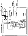
- FIG. 1 is an overall schematic diagram of a variable system for an internal combustion engine according to the present invention.
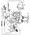
- 1 is an overall perspective view of a variable valve mechanism used in the present invention. It is explanatory drawing explaining the lift characteristic of the intake valve by a variable valve mechanism.
- It is a block diagram which shows the structure of the variable compression ratio mechanism used for this invention, and shows the state controlled to the minimum mechanical compression ratio.
- It is a block diagram which shows the structure of the variable compression ratio mechanism used for this invention, and shows the state currently controlled by the maximum mechanical compression ratio.
- FIG. 6 is a characteristic diagram for explaining the control characteristics shown in FIG. 5 in more detail.
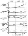
- FIG. 7 is a valve characteristic diagram for further explaining the control characteristics shown in FIG. 6. It is a control flowchart which performs control of the variable system which becomes a 1st embodiment. It is a control flowchart which performs control of the variable system which becomes the 2nd embodiment of the present invention. It is a valve
- FIG. 1 shows the overall configuration of the variable system for an internal combustion engine to which the present invention is applied.
- a piston 01 provided in a cylinder bore formed in a cylinder block SB so as to be slidable up and down by a combustion pressure, etc.
- a pair of intake valves 4 for each cylinder that are slidably provided on the cylinder head SH and open and close the open ends of the intake and exhaust ports IP and EP, respectively.
- An exhaust valve 5 is provided.
- the piston 01 is connected to the crankshaft 02 via a connecting rod 03 composed of a lower link 42 and an upper link 43 described later, and a combustion chamber 04 is formed between the crown surface and the lower surface of the cylinder head SH. Yes.
- a spark plug 05 is provided substantially at the center of the cylinder head SH.
- the intake port IP is connected to an air cleaner (not shown), and intake air is supplied from a compressor 71 of a turbocharger 70 which is a supercharger via an electric throttle valve 72.
- the electric throttle valve 72 is controlled by the controller 22 and basically its opening degree is controlled in accordance with the amount of depression of the accelerator pedal.
- the exhaust port EP discharges exhaust gas to the atmosphere via the exhaust gas purification catalyst 74 and the muffler 75 via the turbine 73 of the turbocharger 70.
- the upstream and downstream of the turbine 73 are connected by an exhaust bypass passage 76, and an electric control wastegate valve 77 is arranged in the middle of the exhaust bypass passage 76.
- the electric control wastegate valve 77 adjusts the amount of exhaust gas flowing into the turbine 73, and thereby adjusts the supercharging pressure of the compressor 71.
- the internal combustion engine includes a first variable valve mechanism as a “lift / operating angle variable mechanism” for controlling the valve lift and the operating angle (open period) of the intake valve 4.
- a first variable valve mechanism as a “lift / operating angle variable mechanism” for controlling the valve lift and the operating angle (open period) of the intake valve 4.
- (Intake VEL) 1 a second variable valve mechanism (intake VTC) 2 that is a “phase angle variable mechanism” that controls the center phase angle of the valve lift of the intake valve 4, and a cylinder mechanical compression ratio ⁇ C (machine A variable compression ratio mechanism (VCR) 3 which is a “piston stroke variable mechanism” for controlling the expansion ratio ⁇ E) is provided.
- VCR variable compression ratio mechanism
- the first variable valve mechanism 1 is an intake valve closing timing variable mechanism that changes the closing timing of the intake valve 4 to change the effective compression ratio by controlling the valve lift and operating angle (open period) of the intake valve 4.
- the specific structure is the same as that described in, for example, “Japanese Patent Application Laid-Open No. 2003-172112” previously filed by the present applicant.
- a hollow drive shaft 6 rotatably supported by a bearing at the upper part of the cylinder head SH, and an eccentric rotary cam fixed to the outer peripheral surface of the drive shaft 6 by press fitting or the like.
- Two drive cams 7 are supported on the outer peripheral surface of the drive shaft 6 so as to be swingable, and are slidably contacted with the upper surface of the valve lifter 8 disposed at the upper end of the intake valve 4 to open the intake valve 4.
- a swing cam 9 and a transmission mechanism that is interposed between the drive cam 7 and the swing cam 9 and converts the rotational force of the drive cam 7 into a swing motion and transmits the swing cam 9 to the swing cam 9 as a swing force. It has.
- the drive shaft 6 receives a rotational force from the crankshaft 02 via a timing chain (not shown) via a timing sprocket 30 provided at one end, and this rotational direction is set in the direction of arrow Rd in FIG. .
- the drive cam 7 has a substantially ring shape, and is fixed to the drive shaft 6 through a drive shaft insertion hole formed in the inner axial direction.
- the shaft center of the cam body has a diameter from the shaft center of the drive shaft 6. Offset by a certain amount in the direction.
- the swing cam 9 has a substantially raindrop shape of the same shape, and is integrally provided at both ends of the annular camshaft 10, and the camshaft 10 is interposed via the inner peripheral surface.
- the drive shaft 6 is rotatably supported.
- a cam surface is formed on the lower surface, and has a base circle surface on the shaft side of the camshaft 10, a ramp surface extending in an arc shape from the base circle surface to the cam nose portion side, and from the ramp surface to the tip side of the cam nose portion.
- a lift surface that is continuous with the top surface of the maximum lift is formed, and the base circle surface, the ramp surface, and the lift surface are in contact with predetermined positions on the upper surface of each valve lifter 8 according to the swing position of the swing cam 9. It has become.
- the transmission mechanism includes a rocker arm 11 disposed above the drive shaft 6, a link arm 12 that links the one end 11 a of the rocker arm 11 and the drive cam 7, and the other end 11 b of the rocker arm 11 and the swing cam 9.
- the link rod 13 to be linked is provided.
- the rocker arm 11 has a cylindrical base portion at the center thereof rotatably supported by a control cam, which will be described later, via a support hole, and one end portion 11 a is rotatably connected to the link arm 12 by a pin 14.
- the other end portion 11 b is rotatably connected to one end portion of the link rod 13 via a pin 15.
- the link arm 12 is formed with a fitting hole in which the cam body of the drive cam 7 is rotatably fitted at the center position of a relatively large-diameter annular base portion 12 a, while the protruding end 12 b is a rocker arm by a pin 14. It is connected to one end 11a.
- the other end of the link rod 13 is rotatably connected to the cam nose of the swing cam 9 via a pin 16.
- the control shaft 17 is rotatably supported by the same bearing member above the drive shaft 6, and is slidably fitted into the support hole of the rocker arm 11 on the outer periphery of the control shaft 17.
- a control cam 18 serving as a moving fulcrum is fixed.
- the control shaft 17 is arranged in the longitudinal direction of the engine in parallel with the drive shaft 6 and is rotationally controlled by the drive mechanism 19.
- the control cam 18 has a cylindrical shape, and the axial center position is deviated from the axial center of the control shaft 17 by a predetermined amount.
- the drive mechanism 19 includes an electric motor 20 that is fixed to one end of a housing (not shown), and a transmission unit 21 that is provided inside the housing and transmits the rotational driving force of the electric motor 20 to the control shaft 17. .
- the electric motor 20 is constituted by a proportional type DC motor, and is driven by a control signal from a controller 22 as an engine control unit for detecting an engine operation state.
- the transmission means 21 includes a ball screw shaft 23 disposed substantially coaxially with the drive shaft of the electric motor 20, a ball nut 24 that is a moving member screwed onto the outer periphery of the ball screw shaft 23, and one end portion of the control shaft 17. And a link member 26 that links the linkage arm 25 and the ball nut 24 together.
- a ball circulation groove having a predetermined width is continuously formed in a spiral shape on the entire outer peripheral surface excluding both ends, and the rotational driving force of the drive shaft of the electric motor 20 coupled to one end is obtained. It is to be transmitted.
- guide grooves for holding a plurality of balls in a freely rotatable manner in cooperation with the ball circulation grooves are formed continuously on the inner peripheral surface in a spiral shape, and the rotational movement of the ball screw shaft 23 via each ball. Is applied to the ball nut 24 while converting it into a linear motion.
- a drive shaft angle sensor 28 that detects the rotation angle of the drive shaft 6 and a rotation angle sensor 29 that detects the rotation angle of the control shaft 17 are provided.
- the second variable valve mechanism 2 is configured such that the sprocket 30 provided at the front end portion of the drive shaft 6 and the sprocket 30 and the drive shaft 6 are relative to each other within a predetermined angle range. And a hydraulic actuator 32 for phase control that rotates in a rotating manner.
- the sprocket 30 is linked to the crankshaft via a timing chain or timing belt (not shown).
- the hydraulic pressure supply to the phase control hydraulic actuator 32 is controlled by a second hydraulic pressure controller (not shown) based on a control signal from the same controller 22.
- a second hydraulic pressure controller (not shown) based on a control signal from the same controller 22.
- the second variable valve mechanism 2 is not limited to a hydraulic type, and various configurations such as those using an electric motor or an electromagnetic actuator are possible. Since these structures are also well known, further explanation is omitted.
- detection signals from the drive shaft angle sensor 28 for detecting the rotation angle of the drive shaft 6 and the rotation angle sensor 29 of the control shaft 17 are input, and signals from the crank angle sensor and the drive shaft angle sensor 28 are input.
- the relative rotational position of the sprocket 30 and the drive shaft 6 described later, that is, the position of the phase variable mechanism 2 is detected.
- the position of the first variable valve mechanism 1 is detected by an information signal from the rotation angle sensor 29 of the control shaft 17.
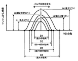
- FIG. 3 shows a change state of the lift and operating angle of the first variable valve mechanism 1 and the second variable valve mechanism 2.
- the intake valve lift can change from the minimum lift L 1 to the first intermediate lift L 2, the second intermediate lift L 3, and the maximum lift L 4.
- the operating angle which is the period, can change from the minimum operating angle D1 to the first intermediate operating angle D2, the second intermediate operating angle D3, and the maximum operating angle D4.
- the second variable valve mechanism 2 does not change the operating angle while maintaining the respective lift characteristics (L1 to L4), so that the lift characteristics are set to the advance side or the retard side as a whole.
- the center phase angle ⁇ can be adjusted by moving.
- variable compression ratio mechanism 3 will be described with reference to FIGS. 1, 4A, and 4B.
- 4A shows the piston position at the compression top dead center at the minimum mechanical compression ratio
- FIG. 4B shows the piston position at the compression top dead center at the maximum mechanical compression ratio.
- the piston position at the exhaust top dead center coincides with the piston position at the compression top dead center shown in FIGS. 4A and 4B in both the minimum mechanical compression ratio and the maximum mechanical compression ratio. ing.
- variable compression ratio mechanism 3 is a mechanism that makes one cycle at a crank angle of 360 °, in principle, the piston position at the compression top dead center and the piston position at the exhaust top dead center coincide with each other. For the same reason, the piston position at the intake bottom dead center and the piston position at the expansion bottom dead center also coincide. This means that the compression stroke between the piston position at the intake bottom dead center and the piston position at the compression top dead center coincides with the expansion stroke between the piston position at the compression top dead center and the piston position at the expansion bottom dead center. It means to do. Therefore, the mechanical compression ratio ⁇ C and the mechanical expansion ratio ⁇ E are in principle coincident.
- the variable compression ratio mechanism 3 has the same configuration as that described in Patent Document 1 described above.
- the crankshaft 02 includes a plurality of journal portions 40 and a crank pin portion 41, and the journal portion 40 is rotatably supported by the main bearing of the cylinder block SB.
- the crankpin portion 41 is eccentric from the journal portion 40 by a predetermined amount, and a lower link 42 serving as a second link is rotatably connected thereto.
- the lower link 42 is configured to be split into two left and right members, and the crank pin portion 41 is fitted in a substantially central connecting hole.
- the upper link 43 serving as the first link has a lower end side rotatably connected to one end of the lower link 42 by a connecting pin 44, and an upper end side rotatably connected to the piston 01 by a piston pin 45.
- the control link 46 serving as the third link is pivotally connected at its upper end side to the other end of the lower link 42 by a connecting pin 47, and the lower end side of the lower part of the cylinder block SB that becomes part of the engine body via the control shaft 48. It is connected to the pivotable.
- the control shaft 48 is rotatably supported by the engine body, and has an eccentric cam portion 48a that is eccentric from the center of rotation, and the lower end portion of the control link 46 is rotatably fitted to the eccentric cam portion 48a. ing.
- the rotation position of the control shaft 48 is controlled by a compression ratio control actuator 49 using an electric motor based on a control signal from the controller 22.
- variable compression ratio mechanism 3 using such a multi-link type piston-crank mechanism, when the control shaft 48 is rotated by the compression ratio control actuator 49, the center position of the eccentric cam portion 48a, particularly with respect to the engine main body. The relative position changes. Thereby, the rocking
- the stroke of the piston 01 changes, and as shown in FIGS. 4A and 4B, the position of the piston 01 at the piston top dead center becomes higher or lower. Thereby, the mechanical compression ratio ⁇ C can be changed.
- This mechanical compression ratio ⁇ C is a geometric compression ratio determined only by the change in the volume of the combustion chamber due to the stroke of the piston 01.
- the cylinder compression volume at the bottom dead center of the intake stroke of the piston 01 and the top dead center of the compression stroke of the piston 01 are determined. It is the ratio of the cylinder volume at the point.
- 4A shows the state of the minimum mechanical compression ratio
- FIG. 4B shows the state of the maximum mechanical compression ratio, respectively, but the compression ratio can be continuously changed between these.
- Min ⁇ C minimum mechanical expansion ratio Min ⁇ E
- Max ⁇ C maximum machine compression
- this embodiment proposes a control method described below.
- the first possibility when the operating region (engine torque) changes is shown. Control operations of the variable valve mechanism 1, the second variable valve mechanism 2, and the variable compression ratio mechanism 3 will be described.
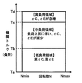
- FIG. 5 shows the division of the operation region according to the engine torque and the rotational speed N.
- the low load region of the low engine torque (Ta to Tb), the medium load region of the medium engine torque (Tb to Tc), and the high engine torque high. It is divided into load areas (Tc to Td). This section is divided into three areas for convenience, but it can also be divided into more areas, and the rotation speed N can be set for each of a plurality of areas.
- the engine torque correlates with the amount of depression of the accelerator pedal, so the engine torque is estimated from the amount of depression of the accelerator pedal.
- the rotation speed N is set so as to change from Nmin assuming an idle rotation state or the like to Nmax assuming a maximum output state or the like. Therefore, it can be determined to which region the current operating state belongs based on the detected rotational speed N and the accelerator pedal depression amount (engine torque).
- the mechanical compression ratio ⁇ C and the mechanical expansion ratio ⁇ E are set to high values in the low load region (Ta to Tb), and the mechanical compression ratio ⁇ C and the mechanical expansion are set in the medium load region (Tb to Tc).
- the ratio ⁇ E is set to a value that decreases as the load increases.
- the mechanical compression ratio ⁇ C and the mechanical expansion ratio ⁇ E are set to values that rapidly increase. Since these are described in detail in FIGS. 6B and 6C, they will be described in detail in FIG.
- boundary portion between the low load region and the medium load region and the boundary portion between the medium load region and the high load region are shown in such a manner that the boundary torque values (Tb, Tc) do not change depending on the rotational speed N.
- a different torque may be set according to the rotational speed N.
- the maximum torque value (Td) set for guaranteeing the durability of the drive system and the like is also shown so as not to change depending on the rotation speed N, but it is set to a different torque value according to the rotation speed N. There is no problem.
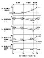
- FIG. 6 shows the control characteristics of the control parameters for each engine torque region controlled by this embodiment.
- the first variable valve mechanism 1, the second variable valve mechanism 2, and the variable compression ratio mechanism 3 are controlled so that the control characteristic of the control parameter is obtained.
- Ta to Td shows the magnitude of the engine torque
- (a) shows the change in supercharging pressure
- (b) shows the change in mechanical compression ratio ⁇ C
- (c) shows the mechanical expansion ratio.
- the change of ⁇ E is shown
- (d) shows the change of the closing timing of the intake valve
- (e) shows the change of the opening timing of the intake valve.
- control characteristic is adopted in which the mechanical compression ratio ⁇ C is “15” and the mechanical expansion ratio ⁇ E is “15” in the low load region, and the engine torque is increased in the medium load region.
- the control characteristics that reduce the mechanical compression ratio ⁇ C from “15” to “9” and the mechanical expansion ratio ⁇ E from “15” to “9” are adopted.
- a control characteristic is adopted in which the mechanical compression ratio ⁇ C is increased from “9” to “15” and the mechanical expansion ratio ⁇ E is increased from “9” to “15”.
- the variable compression ratio mechanism 3 is controlled so as to have a maximum mechanical compression ratio Max ⁇ C shown in FIG. 6B and a maximum mechanical expansion ratio Max ⁇ E shown in FIG. As shown in FIG. 6, the values of the maximum mechanical compression ratio Max ⁇ C and the maximum mechanical expansion ratio Max ⁇ E are controlled to a constant mechanical compression ratio ⁇ C and a mechanical expansion ratio ⁇ E of about “15”, for example.
- the intake valve closing timing IVC is controlled at an earlier time before the intake bottom dead center BDC, such as IVCa to IVCb.
- the opening timing IVO of the intake valve is controlled in the vicinity of the top dead center TDC like IVOa to IVOb.
- Such valve timing can be realized by a combination of the first variable valve mechanism 1 and the second variable valve mechanism 2 as shown in FIG. That is, with respect to the engine torque Ta, the first variable valve mechanism 1 sets the minimum lift L1 / operating angle D1, and the second variable valve mechanism 2 controls the center phase angle ⁇ to the most advanced angle ⁇ a.
- the opening timing IVO is an opening timing IVOa near the top dead center TDC
- the closing timing IVC of the intake valve is a closing timing IVCa sufficiently advanced from the intake bottom dead center BDC.
- the first variable valve mechanism 1 causes the first intermediate lift L2 / slightly larger than the minimum lift L1.
- the operating angle D2 is set, and further, the second variable valve mechanism 2 controls the central phase angle ⁇ b slightly delayed from the most advanced angle ⁇ a.
- the opening timing IVO of the intake valve is set to an opening timing IVOb ( ⁇ IVOa) near the top dead center TDC
- the closing timing IVC is set to a closing timing IVCb slightly advanced from the intake bottom dead center BDC.
- the opening timing IVO of the intake valve hardly changes as shown by IVOa and IVOb, so that the amount of internal EGR captured during the overlap period is stable. Even if there is a transitional change between the low load regions (Ta to Tb), the internal EGR amount does not change, so that stable combustion can be realized.
- the intake valve closing timing IVC is set so as to close the intake valve early.
- the decrease in the temperature (effective compression ratio) at the compression top dead center due to the acceleration of the time can be offset, and thereby better combustion can be realized.
- the mechanical expansion ratio ⁇ E is a large value such as “15”, the expansion work is increased and the theoretical thermal efficiency is also improved, so that the fuel consumption in the low load region (Ta to Tb) can be remarkably improved.
- the second intermediate lift L3 larger than the first intermediate lift L2 is caused by the first variable valve mechanism 1.
- the operating angle D3 is further controlled by the second variable valve mechanism 2 to the central phase angle ⁇ c delayed from the central phase angle ⁇ b.
- the opening timing IVO of the intake valve is set to an opening timing IVOc ( ⁇ IVOa, IVOb) near the top dead center TDC
- the closing timing IVC is set to a closing timing IVCc slightly retarded from the intake bottom dead center BDC.
- the mechanical compression ratio ⁇ C is set to “15” in the middle load region (Tb to Tc). Control is performed so as to gradually decrease from “9” to “9”. Further, as shown in FIG. 6C, the mechanical expansion ratio ⁇ E gradually increases from “15” to “9” as the mechanical compression ratio ⁇ C decreases in the middle load region (Tb to Tc). It will be lowered.
- the waste gate valve 77 is largely opened and bypassed so that a considerable amount of exhaust gas does not flow to the turbocharger, thereby increasing the boost pressure by the turbocharger 70. Suppressed. This makes it possible to control so as not to exceed the maximum engine torque Td.
- the mechanical expansion ratio ⁇ E is greatly reduced, not only the thermal efficiency is lowered and the fuel consumption is deteriorated, but also the exhaust gas temperature is decreased. As the engine pressure increases, there is a risk of causing a problem such that heat damage of the exhaust system components is likely to occur near the engine maximum torque Td.
- the waste gate valve 77 is opened, it means that the high-temperature exhaust gas directly acts on the exhaust system parts without passing through the turbocharger 70 having a heat capacity and a cooling effect. There is a risk of becoming noticeable.
- the vicinity of the maximum engine torque indicates, for example, a case where the opening degree of the throttle valve is 80% or more.
- the second variable valve mechanism 1 causes the second intermediate lift mechanism 1 to move as shown in FIG.
- the maximum lift L4 / operating angle D4 is larger than L3, and the second variable valve mechanism 2 controls the central phase angle ⁇ d, which is delayed more than the central phase angle ⁇ c.
- the opening timing IVO of the intake valve is set to an opening timing IVOd ( ⁇ IVOa, IVOb, IVOc) near the top dead center TDC
- the closing timing IVC is set to a closing timing IVCd that is delayed more than the intake bottom dead center BDC.
- the intake charge efficiency can be reduced.
- the engine torque can be suppressed to the vicinity of the maximum engine torque Td without opening the waste gate valve 73, and the closing timing IVC of the intake valve is set to the closing timing IVCd that is delayed more than the intake bottom dead center BDC.
- the effective compression ratio (actual compression ratio) can be reduced to increase the knock resistance.
- the closing timing IVCd of the intake valve close to the intake bottom dead center BDC is set to the closing timing IVCd, so that the charging efficiency is reduced, but in addition to the increase in torque due to the improvement in knock resistance, the large mechanical expansion ratio ⁇ Ed Since torque increase (increase in combustion work) can be obtained, it is also possible to obtain a combined effect of suppressing the decrease in maximum torque value (for example, unintended torque drop) and ensuring the target maximum engine torque Td.
- the opening timing IVO of the intake valve is set to be substantially constant in the vicinity of the top dead center TDC in response to an increase in engine torque.
- the intake valve closing timing IVC is determined from the phase angle advanced from the intake bottom dead center BDC to the predetermined first region (low load region) and second region (medium load region). The phase angle is gradually retarded to a phase angle that is retarded from the point BDC, and in the predetermined third region (high load region), the phase angle is retarded more than the intake bottom dead center BDC as compared to the second region. ing.
- the intake valve closing timing is retarded from the intake bottom dead center BDC in the vicinity of the maximum engine torque, thereby reducing the effective compression ratio and improving the knock resistance, and the mechanical expansion ratio ⁇ E.
- it is possible to improve the thermal efficiency ( improve the fuel efficiency) and to reduce the exhaust gas temperature to suppress the heat damage of the exhaust system parts.
- FIG. 8 is a control flow in which the activation is performed at the activation timing that arrives at every predetermined time, and is activated again when the next activation timing arrives when all the predetermined control steps are executed.
- step S10 in order to estimate the target engine torque, the engine speed N and the accelerator opening ⁇ are read. In addition, since the operation information other than these operation information can be used for the estimation of the engine torque, the engine torque may be used as needed.
- the process proceeds to step S11.
- step S11 based on the read rotation speed N and accelerator opening degree ⁇ , the target torque T is calculated using a predetermined arithmetic expression and map. This target torque T is used to determine the operating range shown in FIG. 5, and the first variable valve mechanism 1, the second variable valve mechanism 2, and the variable compression ratio correspond to the engine torque shown in FIG. This is used for calculating the control amount of the mechanism 3.
- the process proceeds to step S12.
- step S12 the control amount of the first variable valve mechanism 1 is calculated according to the characteristics shown in FIG. In this case, basically, the lift characteristic of the intake valve is determined. As shown in FIG. 7, the valve lift is determined by the magnitude of the engine torque. These control characteristics are stored in a map using engine torque as a parameter, and appropriate values are set by matching work (matching). The control characteristics of the second variable valve mechanism 2 and the variable compression ratio mechanism 3 described below are also stored in the map in the same manner. When the valve lift is determined, the process proceeds to step S13.
- step S13 the control amount of the second variable valve mechanism 2 is calculated according to the characteristics shown in FIG.
- the center phase angle of the intake valve is basically determined. As shown in FIG. 7, the center phase angle is determined by the magnitude of the engine torque. In this case, the center phase angle is determined so as to obtain the opening timing IVO and the closing timing IVC of the intake valve shown in FIG. 7 in cooperation with the first variable valve mechanism 1.
- the process proceeds to step S14.
- step S14 the control amount of the variable compression ratio mechanism 3 is calculated in accordance with the characteristics shown in FIG.
- the piston stroke characteristic is basically determined as shown in FIGS. 4A and 4B.
- the process proceeds to step S15.
- step S15 the control shown in FIGS. 6 and 7 is performed based on the control amounts of the first variable valve mechanism 1, the second variable valve mechanism 2, and the variable compression ratio mechanism 3 obtained in steps S12, S13, and S14.
- the first variable valve mechanism 1, the second variable valve mechanism 2, and the variable compression ratio mechanism 3 are driven and controlled so as to have characteristics.
- this drive control is completed, the process returns to the return and enters a standby state until the start timing comes again.
- the engine torque Tc and the engine torque Td are substantially matched, that is, a high load region is not particularly provided, and the mechanical expansion ratio ⁇ Ec is shifted to the mechanical expansion ratio ⁇ Ed with a slight time difference. It is also possible to shift from the closing timing IVCc to the closing timing IVCd.
- a method for closing and controlling the waste gate valve 73 when the engine torque reaches the maximum engine torque Td set for guaranteeing the durability of the drive system has been proposed.
- the difference is that the wastegate valve 77 is opened and controlled near the maximum engine torque Td.
- the closing timing IVC of the intake valve at the maximum engine torque Td is different in that it is not the retarded closing timing IVCd but the advanced timing closing timing IVCdad. Note that the closing timing IVCadd has substantially the same characteristics as the closing timing IVCa in the low load region.
- the closing timing IVC of the intake valve at the maximum engine torque Td is set on the retard side as in the first embodiment with reference to the intake bottom dead center BDC, and in this embodiment. In some cases, it may be set to the advance side. For this reason, in the present invention, the closing timing IVCd set on the retard side and the closing timing IVCdad set on the advance side can be combined and expressed by the superordinate concept as “closing timing IVC separated from the intake bottom dead center BDC”. .
- step S16 it is determined in step S16 whether or not the target engine torque T obtained in step S11 has reached the maximum engine torque Td. If the engine torque T has not reached the maximum engine torque calculation Td, the process proceeds to step S12, and the control shown in FIG. 8 is executed. Since the control at this time has been described with reference to FIG. On the other hand, when it is determined that the engine torque T has reached the maximum engine torque calculation Td, the routine proceeds to step S17.
- step S17 the first variable valve mechanism 1 and the second variable valve mechanism 2 are controlled to the lift characteristic L1 indicated by the broken lines in FIG. 6 (d) and FIG. 7 (d). That is, the intake valve closing timing IVC is controlled at an earlier time before the intake bottom dead center BDC, like the closing timing IVCadd. Further, as shown in FIG. 6 (e) and FIG. 7 (d), the opening timing IVO of the intake valve is controlled in the vicinity of the top dead center TDC like IVOd. Since the variable compression ratio mechanism 3 has the control characteristics as described above, the description thereof is omitted.
- step S18 the supercharging pressure (intake pipe pressure) due to the supercharging action of the turbocharger 70 is detected.
- this supercharging pressure is obtained, the process proceeds to step S19.
- step S19 a predicted engine torque Tp when the waste gate valve 77 is assumed to be fully closed is estimated.
- the intake pipe pressure (supercharging pressure) is detected, and it is assumed that the wastegate valve 77 is fully closed.
- Predictive engine torque Tp is estimated and calculated.
- the process proceeds to step S20.
- step S21 since the predicted engine torque Tp is larger than the target engine torque T, a waste gate target valve opening amount ⁇ w for reducing the predicted engine torque Tp to the maximum engine torque Td is calculated.
- step S22 the waste gate valve is calculated. 77 is driven and controlled to the target valve opening amount ⁇ w. When the control of the waste gate valve 77 is completed, the process proceeds to step S23.
- step 23 and 24 the intake pipe pressure (supercharging pressure) is re-detected, and the actual engine torque Tac is calculated based on this.
- the process proceeds to step S25.
- step S25 it is determined whether or not the actual engine torque Tac matches the maximum engine torque Td (within a predetermined range). If it is determined in this determination that the actual engine torque Tac coincides with the maximum engine torque Td, the actual engine torque Tac is determined to have reached the maximum engine torque Td, and the process returns to the return. On the other hand, when the actual engine torque Tac does not coincide with the maximum engine torque Td (when there is some difference), the process returns to step S18 again, and the same control step is executed.
- the intake valve advanced from the high mechanical expansion ratio ⁇ Ed and the intake bottom dead center BDC also when the waste gate valve 77 is opened to suppress to the predetermined maximum engine torque.
- the lift characteristic of the intake valve is the low lift characteristic L1
- the absolute amount of exhaust gas can be reduced, the absolute amount of exhaust gas passing through the waste gate valve 77 can be reduced, and exhaust with a high mechanical expansion ratio ⁇ Ed can be achieved. Due to the synergistic effect with the gas temperature reduction effect, it is possible to further suppress the heat damage of the exhaust system components in the downstream.
- the closing timing IVCa to IVCb of the intake valve in the low load region is a so-called “early closing mirror cycle” in which the pumping loss is reduced by advancing the closing timing IVC from the intake bottom dead center BDC.
- the example is proposed.
- the closing timing IVC is retarded from the intake bottom dead center BDC as indicated by the closing timing IVCd.
- This is an example of a so-called “slow closing mirror cycle” for reducing the loss, and proposes an example of a variable valve operating form different from the first embodiment. This embodiment of the “slow closing mirror cycle” will be described with reference to FIG.
- the lift characteristic is controlled by using the first variable valve mechanism 1, but in this embodiment, the lift amount characteristic of the intake valve is only the maximum lift characteristic L4, and the first possible The variable valve mechanism 1 (intake VEL) is not used and is controlled by the second variable valve mechanism 2 (intake VTC).
- the third variable valve mechanism exhaust VTC having the same mechanism as the second variable valve mechanism 2 is also used on the exhaust side.
- the lift characteristic at the maximum engine torque Td is the same as the lift characteristic shown in FIG. 7D of the first embodiment.
- the lift characteristic is the maximum lift characteristic L4, the center phase angle is the phase angle ⁇ d, and the intake valve closing timing IVCd.
- valve lift characteristics at the engine torque Ta in the low load region will be described.
- the valve characteristics of the intake valve and the exhaust valve substantially coincide with the valve characteristics at the maximum engine torque Td shown in FIG. 10 (d). That is, the closing timing IVCam of the intake valve in FIG. 10 (a) substantially coincides with the closing timing IVCd in FIG. 10 (d), and as described above, the “delayed closing mirror cycle” is set, and the low engine torque Ta The fuel consumption is reduced by reducing the pump loss. Further, the valve overlap is also almost “0”, which can suppress instability of combustion due to residual gas.
- the center phase angle of the exhaust valve is controlled by the third variable valve in the advance direction by a difference ⁇ as compared with the engine torque Ta.
- the difference ⁇ is “ ⁇ am ⁇ bm”, that is, “IVCam ⁇ IVCbm”, and the valve overlap is substantially maintained at “0”. Therefore, as in the case of the engine torque Ta, the amount of residual gas in the cylinder can be reduced to suppress combustion fluctuations and combustion instability.
- the closing timing IVC of the intake valve is advanced to the closing timing IVCcm and brought closer to the intake bottom dead center BDC side, and the charging efficiency is increased.
- This closing time IVCcm substantially coincides with IVCc in FIG. 7C of the first embodiment, and is the closing time IVC at which the charging efficiency is increased.
- the exhaust valve is controlled to move backward by ⁇ and return to the original position.
- FIG. 10 (c) since the valve overlap becomes large, it is considered that a large amount of residual gas remains in the cylinder and the combustion state becomes unstable. In this way, the combustion state can be improved.
- the opening timing of the exhaust valve is retarded and the central phase of the valve overlap is advanced. Therefore, the valve overlap time comes within a relatively short time after the exhaust valve is opened. That is, the exhaust valve is opened, and the pressure of the exhaust pipe near the exhaust valve increases, and the high pressure wave moves downstream, reflects off the end of the exhaust pipe, and returns to the vicinity of the exhaust valve again. Since the overlap time comes before the pressure wave returns, high-pressure exhaust gas is prevented from being introduced into the cylinder as residual gas through the exhaust valve, which prevents the combustion from becoming unstable. It becomes possible to suppress.
- the closing timing IVC is retarded to the closing timing IVCd and is controlled to the high mechanical expansion ratio ⁇ Ed, so that the engine torque is suppressed to the maximum engine torque Td.
- reduce the exhaust gas temperature by suppressing the heat damage of the exhaust system parts.
- variable compression ratio mechanism 3 used in the first to third embodiments is a mechanism that makes one cycle at a crank angle of 360 °, and in principle, the piston position at the compression top dead center and the piston position at the exhaust top dead center. Is in agreement. For the same reason, the piston position at the intake bottom dead center and the piston position at the expansion bottom dead center also coincide. Therefore, the mechanical compression ratio ⁇ C and the mechanical expansion ratio ⁇ E are in principle coincident.
- variable compression ratio mechanism 3 used in the fourth embodiment is a mechanism that makes one cycle at a crank angle of 720 °. Therefore, the mechanical compression ratio ⁇ C and the mechanical expansion ratio ⁇ E are different from each other. Can be controlled.
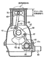
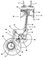
- a schematic configuration of the variable compression ratio mechanism 3 having a different form will be briefly described with reference to FIG. The detailed description is described in “Japanese Patent Laid-Open No. 2016-017489” filed earlier by the present applicant.
- the internal combustion engine 51 includes a piston 54 that reciprocates in a vertical direction along a cylinder bore 53 formed in the cylinder block 52, and a piston pin 55 and a link mechanism 57 of a piston position changing mechanism 56 by the vertical movement of the piston 54. And a crankshaft 58 that is rotationally driven.
- a space defined between the crown surface of the piston 54 and the combustion chamber boundary indicated by a one-dot chain line above the crown surface is an in-cylinder volume (combustion chamber volume).
- the piston position changing mechanism 56 includes a link mechanism 57 composed of a plurality of links, a link posture changing mechanism 59 that changes the posture of the link mechanism 57, and the like.
- the link mechanism 57 is connected to the piston 54 via a piston pin 55 and is connected to the upper link 7 via a first connection pin 61 so as to be swingable.
- a lower link 63 rotatably connected to the lower link 63, and a control link connected to the lower link 63 via a second connection pin 64 so as to be swingable and rotatably connected to an eccentric cam portion 66 of the control shaft 65.
- -Relink 67 is a link mechanism 57 composed of a plurality of links, a link posture changing mechanism 59 that changes the posture of the link mechanism 57, and the like.
- the link mechanism 57 is connected to the piston 54 via a piston pin 55 and is connected to the upper link 7 via a first connection pin 61 so as to be swingable.
- a lower link 63 rotatably connected to the lower
- first gear 68 that is a driving rotator is fixed to the front end of the crankshaft 58
- second gear 69 that is a driven rotator on the front end side of the control shaft 65.
- the first gear 68 and the second gear 69 mesh with each other so that the rotational force of the crankshaft 58 is transmitted to the control shaft 65 via the link attitude changing mechanism 59.
- the first gear 68 has an outer diameter that is approximately half the outer diameter of the second gear 69, and therefore the rotational speed of the crankshaft 58 is the difference between the outer diameters of the first gear 68 and the second gear 69.
- the control shaft 65 is transmitted to the control shaft 65 after being decelerated to a half angular velocity.
- the phase of the control shaft 65 with respect to the second gear 69 is changed by the link posture changing mechanism 59, that is, the relative rotational phase with respect to the crankshaft 58 is changed.
- crankshaft 58 and the control shaft 65 are rotatably supported by two common front and rear bearing members provided in the cylinder block. Further, the eccentric cam portion 66 is rotatably connected to a large diameter portion formed at the lower end portion of the control link 67 via a needle bearing 70.
- the mechanical compression ratio ⁇ C and the mechanical expansion ratio ⁇ E can be controlled to be different from each other, as described in the above-mentioned “Japanese Patent Laid-Open No. 2016-017489”.
- Japanese Patent Laid-Open No. 2016-017489 Japanese Patent Laid-Open No. 2016-017489.
- the thermal efficiency is improved and the exhaust gas temperature is lowered to reduce the exhaust system component. It suppresses heat damage.
- FIG. 12 shows the control characteristics of the control parameters for each engine torque region, similar to FIG. 6 of the first embodiment.
- the first variable valve mechanism 1, the second variable valve mechanism 2, and the variable compression ratio mechanism 3 are controlled so that the control characteristic of the control parameter is obtained.
- the control characteristics of the supercharging pressure, the intake valve closing timing IVC, and the intake valve opening timing IVO are the same as those in the first embodiment, the description thereof will be omitted.
- the control characteristic is adopted in which the mechanical compression ratio ⁇ C is “11” and the mechanical expansion ratio ⁇ E is “15” in the low load region, and the engine torque in the medium load region.
- the mechanical compression ratio ⁇ C is increased from “11” to “12” and the mechanical expansion ratio ⁇ E is decreased from “15” to “12”.
- the mechanical compression ratio ⁇ C is decreased from “12” to “11” and the mechanical expansion ratio ⁇ E is increased from “12” to “15” corresponding to the increase in the engine torque.
- the characteristic is adopted.
- the mechanical compression ratio ⁇ C and the mechanical expansion ratio ⁇ E are set to substantially constant control characteristics even when the engine torque increases. That is, the mechanical expansion ratio ⁇ E is set as large as “15”, and the mechanical compression ratio ⁇ C is set as small as “11”. Accordingly, the work of combustion is increased by setting the mechanical expansion ratio ⁇ E to a large value of “15”, and the mechanical compression ratio ⁇ C is set to a value that is slightly suppressed to “11”. By suppressing the gas temperature, it is possible to suppress the cooling loss, thereby increasing the thermal efficiency and further improving the fuel consumption.
- the control characteristic of the low load region is changed to the control characteristic of the middle load region, and the mechanical expansion ratio ⁇ E is changed from “15” to “12” at the engine torque Tc.
- the mechanical compression ratio ⁇ C is changed from “11” to “12”.
- the mechanical expansion ratio ⁇ E and the mechanical compression ratio ⁇ C are set to “9” in the engine torque Tc.
- the mechanical expansion ratio ⁇ E and the mechanical compression ratio ⁇ C are “12”. Therefore, the intake ratio (intake stroke) is also increased, and the engine torque can be easily increased.
- the control characteristics of the medium load range are changed to the control characteristics of the high load range, and the maximum engine set for guaranteeing the durability of the drive system etc.
- the mechanical expansion ratio ⁇ E is changed and set from “12” to “15”
- the effective compression ratio actual compression ratio
- the intake valve closing timing IVC is retarded or advanced from the intake bottom dead center BDC in order to avoid knocking at the maximum engine torque Td. This means that the amount to be reduced, that is, the reduction amount of the effective compression ratio due to the closing timing IVC is reduced.
- the retard amount of the closing timing IVCd of the present embodiment can be made smaller than the closing timing IVCd of the first embodiment indicated by “ ⁇ ”.
- the advance amount of the closing timing IVCadd of this embodiment can be made smaller than the closing timing IVCadd of the second embodiment indicated by “ ⁇ ”.
- the maximum engine torque Td set for guaranteeing durability of the drive system and the internal combustion engine is substantially constant regardless of the change in the rotational speed.
- the maximum engine torque Td may be set so as to change in response to the change in the rotational speed. Further, the maximum engine torque Td may be set not only for ensuring the durability of the drive system but also for the durability of engine components such as pistons in the internal combustion engine and the vibration limit of the internal combustion engine.
- variable valve mechanism has shown an example in which a variable lift / operating angle mechanism for controlling the valve lift and operating angle of the intake valve and a variable phase mechanism for controlling the lift center phase angle of the intake valve are shown.
- the closing timing IVC can be changed, any method can be used.
- the variable compression ratio mechanism for controlling the mechanical compression ratio ⁇ C and the mechanical expansion ratio ⁇ E in the cylinder has shown two methods, but any method can be used as long as the mechanical expansion ratio ⁇ E can be changed. Is.
- variable valve mechanism separates the intake valve closing timing from the intake bottom dead center, and the variable compression ratio mechanism The expansion ratio was increased.
- An internal combustion engine variable system comprising a variable valve mechanism for controlling the closing timing of the intake valve, and a control means for controlling the variable compression ratio mechanism for controlling the mechanical compression ratio and the mechanical expansion ratio.
- the variable valve mechanism and the variable compression ratio mechanism are controlled by a first region where the engine torque is small, a second region where the engine torque is medium, and a third region where the engine torque is large.
- the control means maintains the mechanical expansion ratio at the first mechanical expansion ratio in the first region, sets the closing timing of the intake valve to an advance side from the intake bottom dead center, and in the second region, The first mechanical expansion ratio is decreased to the second mechanical expansion ratio in response to the increase in the engine torque, and the closing timing of the intake valve is set to the advance of the intake bottom dead center in response to the increase in the engine torque.
- the second mechanical expansion ratio is increased to the third mechanical expansion ratio in response to the increase in the engine torque
- the closing timing of the intake valve is set in response to the increase in the engine torque. It is set on the retard side further than the retard side in the case of the second region.
- control of a variable system of an internal combustion engine provided with a variable valve mechanism for controlling the closing timing of the intake valve and a control means for controlling the variable compression ratio mechanism for controlling the mechanical compression ratio and the mechanical expansion ratio.
- the closing timing of the intake valve is set to an advance side from the intake bottom dead center, and when the engine torque is maximum, the closing timing of the intake valve is set. Is set to the retard side from the intake bottom dead center, the mechanical compression ratio and the mechanical expansion ratio are set to a first value, and the engine torque is in a state between the low engine torque and the maximum engine torque. Then, the closing timing of the intake valve is set to the closing timing between the low engine torque and the maximum engine torque, and the mechanical compression ratio and the mechanical expansion ratio are set to a second value smaller than the first value. Set to value.
- this invention is not limited to above-described embodiment, Various modifications are included.
- the above-described embodiment has been described in detail for easy understanding of the present invention, and is not necessarily limited to one having all the configurations described.
- a part of the configuration of an embodiment can be replaced with the configuration of another embodiment, and the configuration of another embodiment can be added to the configuration of an embodiment.
Landscapes
- Engineering & Computer Science (AREA)
- Mechanical Engineering (AREA)
- General Engineering & Computer Science (AREA)
- Chemical & Material Sciences (AREA)
- Combustion & Propulsion (AREA)
- Output Control And Ontrol Of Special Type Engine (AREA)
- Supercharger (AREA)
- Valve Device For Special Equipments (AREA)
- Control Of Throttle Valves Provided In The Intake System Or In The Exhaust System (AREA)
- Electrical Control Of Air Or Fuel Supplied To Internal-Combustion Engine (AREA)
- Combined Controls Of Internal Combustion Engines (AREA)
Abstract
Dans la présente invention, lorsque le couple moteur a augmenté jusqu'à proximité du couple maximal, le calage de fermeture IVC de la soupape d'admission est éloigné du point mort bas d'admission BDC par un mécanisme de soupape variable, et le rapport d'expansion mécanique εE est augmenté par un mécanisme de taux de compression variable. Au voisinage du couple moteur maximal, le calage de fermeture IVC de la soupape d'admission est réglé à un calage de fermeture IVCd qui est éloigné du point mort bas d'admission BDC. Ainsi, le taux de compression effectif est réduit, la résistance au cognement est augmentée, et le rapport d'expansion mécanique peut être augmenté, ce qui permet d'améliorer l'efficacité thermique, de réduire la température des gaz d'échappement et de réduire la détérioration thermique des composants du système d'échappement.
Priority Applications (3)
| Application Number | Priority Date | Filing Date | Title |
|---|---|---|---|
| CN201780070488.7A CN109937291A (zh) | 2016-11-15 | 2017-11-01 | 内燃机的可变系统及其控制方法 |
| US16/349,218 US20190285005A1 (en) | 2016-11-15 | 2017-11-01 | Variable system of internal combustion engine and method for controlling the same |
| DE112017005745.0T DE112017005745T5 (de) | 2016-11-15 | 2017-11-01 | Variables System für Brennkraftmaschine und Steuerverfahren hierfür |
Applications Claiming Priority (2)
| Application Number | Priority Date | Filing Date | Title |
|---|---|---|---|
| JP2016222180A JP6666232B2 (ja) | 2016-11-15 | 2016-11-15 | 内燃機関の可変システム及びその制御方法 |
| JP2016-222180 | 2016-11-15 |
Publications (1)
| Publication Number | Publication Date |
|---|---|
| WO2018092586A1 true WO2018092586A1 (fr) | 2018-05-24 |
Family
ID=62146251
Family Applications (1)
| Application Number | Title | Priority Date | Filing Date |
|---|---|---|---|
| PCT/JP2017/039506 Ceased WO2018092586A1 (fr) | 2016-11-15 | 2017-11-01 | Système de variation destiné à un moteur à combustion interne et procédé de commande associé |
Country Status (5)
| Country | Link |
|---|---|
| US (1) | US20190285005A1 (fr) |
| JP (1) | JP6666232B2 (fr) |
| CN (1) | CN109937291A (fr) |
| DE (1) | DE112017005745T5 (fr) |
| WO (1) | WO2018092586A1 (fr) |
Families Citing this family (6)
| Publication number | Priority date | Publication date | Assignee | Title |
|---|---|---|---|---|
| US10801417B1 (en) * | 2019-07-12 | 2020-10-13 | GM Global Technology Operations LLC | Methods and systems for regulating exhaust gas flow |
| DE102019135344A1 (de) * | 2019-12-20 | 2021-06-24 | Bayerische Motoren Werke Aktiengesellschaft | Verfahren zum Betreiben einer Brennkraftmaschinenanordnung eines Fahrzeugs |
| US11465518B2 (en) * | 2020-04-17 | 2022-10-11 | Hamilton Sundstrand Corporation | Charging scheme for electric propulsion systems |
| JP7816092B2 (ja) * | 2022-11-28 | 2026-02-18 | トヨタ自動車株式会社 | 水素エンジンの制御装置 |
| US12326108B1 (en) * | 2023-12-01 | 2025-06-10 | Fca Us Llc | System and method for determining available engine torque based on cold light off catalyst |
| CN118188155A (zh) * | 2024-03-12 | 2024-06-14 | 李斯特技术中心(天津)有限公司 | 一种用于发动机的高膨胀比多连杆机构 |
Citations (7)
| Publication number | Priority date | Publication date | Assignee | Title |
|---|---|---|---|---|
| JP2006097657A (ja) * | 2004-09-30 | 2006-04-13 | Mazda Motor Corp | 4サイクルエンジン |
| JP2008196407A (ja) * | 2007-02-14 | 2008-08-28 | Toyota Motor Corp | 内燃機関 |
| JP2013160185A (ja) * | 2012-02-07 | 2013-08-19 | Toyota Motor Corp | エンジン |
| JP2014185569A (ja) * | 2013-03-22 | 2014-10-02 | Toyota Motor Corp | 火花点火式内燃機関 |
| JP2016017489A (ja) * | 2014-07-10 | 2016-02-01 | 日立オートモティブシステムズ株式会社 | 内燃機関の制御装置 |
| JP2016142255A (ja) * | 2015-02-05 | 2016-08-08 | 日野自動車株式会社 | 可変膨張比機構 |
| WO2016167186A1 (fr) * | 2015-04-17 | 2016-10-20 | 日立オートモティブシステムズ株式会社 | Dispositif de réglage de taux de compression pour moteur à combustion interne |
Family Cites Families (14)
| Publication number | Priority date | Publication date | Assignee | Title |
|---|---|---|---|---|
| US8215292B2 (en) * | 1996-07-17 | 2012-07-10 | Bryant Clyde C | Internal combustion engine and working cycle |
| JP4581273B2 (ja) | 2001-03-19 | 2010-11-17 | 日産自動車株式会社 | 内燃機関の起動制御装置 |
| JP2003172112A (ja) | 2001-12-04 | 2003-06-20 | Hitachi Unisia Automotive Ltd | 内燃機関の可変動弁装置 |
| JP4416377B2 (ja) * | 2002-05-16 | 2010-02-17 | 日産自動車株式会社 | 内燃機関の制御装置 |
| DE102004026157B4 (de) * | 2003-05-30 | 2017-11-09 | Honda Motor Co., Ltd. | Ventilzeitsteuerungs-Steuer-/Regelsystem und Steuer-/Regelsystem für einen Verbrennungsmotor |
| JP4188158B2 (ja) * | 2003-07-03 | 2008-11-26 | 本田技研工業株式会社 | 内燃機関の制御装置 |
| JP4082596B2 (ja) * | 2003-07-07 | 2008-04-30 | 本田技研工業株式会社 | 制御装置 |
| US7765966B2 (en) * | 2006-03-09 | 2010-08-03 | Ford Global Technologies, Llc | Hybrid vehicle system having engine with variable valve operation |
| JP4725561B2 (ja) * | 2007-08-13 | 2011-07-13 | トヨタ自動車株式会社 | 火花点火式内燃機関 |
| JP6320882B2 (ja) * | 2014-09-11 | 2018-05-09 | 日立オートモティブシステムズ株式会社 | 内燃機関の可変燃焼システム |
| JP2016222180A (ja) | 2015-06-02 | 2016-12-28 | 富士重工業株式会社 | 車両操舵制御装置 |
| JP6564652B2 (ja) * | 2015-09-03 | 2019-08-21 | 日立オートモティブシステムズ株式会社 | 内燃機関の圧縮比調整装置及び内燃機関の圧縮比調整装置の制御方法 |
| JP6494502B2 (ja) * | 2015-12-24 | 2019-04-03 | 日立オートモティブシステムズ株式会社 | 内燃機関のピストンストローク調整装置 |
| CN105888832B (zh) * | 2016-06-05 | 2018-05-22 | 吉林大学 | 米勒循环柴油-天然气双燃料发动机及其控制方法 |
-
2016
- 2016-11-15 JP JP2016222180A patent/JP6666232B2/ja not_active Expired - Fee Related
-
2017
- 2017-11-01 CN CN201780070488.7A patent/CN109937291A/zh active Pending
- 2017-11-01 WO PCT/JP2017/039506 patent/WO2018092586A1/fr not_active Ceased
- 2017-11-01 US US16/349,218 patent/US20190285005A1/en not_active Abandoned
- 2017-11-01 DE DE112017005745.0T patent/DE112017005745T5/de not_active Withdrawn
Patent Citations (7)
| Publication number | Priority date | Publication date | Assignee | Title |
|---|---|---|---|---|
| JP2006097657A (ja) * | 2004-09-30 | 2006-04-13 | Mazda Motor Corp | 4サイクルエンジン |
| JP2008196407A (ja) * | 2007-02-14 | 2008-08-28 | Toyota Motor Corp | 内燃機関 |
| JP2013160185A (ja) * | 2012-02-07 | 2013-08-19 | Toyota Motor Corp | エンジン |
| JP2014185569A (ja) * | 2013-03-22 | 2014-10-02 | Toyota Motor Corp | 火花点火式内燃機関 |
| JP2016017489A (ja) * | 2014-07-10 | 2016-02-01 | 日立オートモティブシステムズ株式会社 | 内燃機関の制御装置 |
| JP2016142255A (ja) * | 2015-02-05 | 2016-08-08 | 日野自動車株式会社 | 可変膨張比機構 |
| WO2016167186A1 (fr) * | 2015-04-17 | 2016-10-20 | 日立オートモティブシステムズ株式会社 | Dispositif de réglage de taux de compression pour moteur à combustion interne |
Also Published As
| Publication number | Publication date |
|---|---|
| CN109937291A (zh) | 2019-06-25 |
| JP2018080605A (ja) | 2018-05-24 |
| DE112017005745T5 (de) | 2019-08-14 |
| JP6666232B2 (ja) | 2020-03-13 |
| US20190285005A1 (en) | 2019-09-19 |
Similar Documents
| Publication | Publication Date | Title |
|---|---|---|
| WO2018092586A1 (fr) | Système de variation destiné à un moteur à combustion interne et procédé de commande associé | |
| JP3912147B2 (ja) | 内燃機関の可変動弁装置 | |
| JP4931740B2 (ja) | 内燃機関の制御装置 | |
| US7451739B2 (en) | Ignition timing control system and method for internal combustion engine, and engine control unit | |
| CN105324562B (zh) | 可变气门机构的控制装置 | |
| US8001936B2 (en) | Control apparatus for internal combustion engine and control method therefor | |
| JP4727518B2 (ja) | 内燃機関の制御装置 | |
| JPH04246249A (ja) | 内燃機関の実圧縮比制御装置 | |
| WO2019035312A1 (fr) | Système de fonctionnement variable pour moteur à combustion interne et son dispositif de commande | |
| JP4749988B2 (ja) | 内燃機関の始動制御装置 | |
| JP6564652B2 (ja) | 内燃機関の圧縮比調整装置及び内燃機関の圧縮比調整装置の制御方法 | |
| JP4345197B2 (ja) | 内燃機関のノッキング制御装置 | |
| WO2014162517A1 (fr) | Dispositif de commande de mécanisme de soupape variable | |
| JP2007239555A (ja) | 内燃機関 | |
| JP5227265B2 (ja) | 排気過給機を備える内燃機関 | |
| JP6348833B2 (ja) | 内燃機関の可変動弁システム及び可変動弁制御装置 | |
| JP6753530B2 (ja) | 内燃機関の制御方法および制御装置 | |
| JP5434243B2 (ja) | 可変圧縮比式内燃機関 | |
| WO2018211853A1 (fr) | Système de fonctionnement variable de moteur à combustion interne et son dispositif de commande | |
| JP5169682B2 (ja) | 内燃機関を制御する方法及び内燃機関システム | |
| JP2007182828A (ja) | 内燃機関の制御装置 | |
| WO2020008941A1 (fr) | Système de commande de moteur à combustion interne et dispositif de commande pour ce dernier | |
| JP4962580B2 (ja) | 内燃機関の制御装置 | |
| JP2013133745A (ja) | 内燃機関の制御装置 |
Legal Events
| Date | Code | Title | Description |
|---|---|---|---|
| 121 | Ep: the epo has been informed by wipo that ep was designated in this application |
Ref document number: 17872482 Country of ref document: EP Kind code of ref document: A1 |
|
| 122 | Ep: pct application non-entry in european phase |
Ref document number: 17872482 Country of ref document: EP Kind code of ref document: A1 |