WO2016181511A1 - Oscillateur laser à gaz - Google Patents
Oscillateur laser à gaz Download PDFInfo
- Publication number
- WO2016181511A1 WO2016181511A1 PCT/JP2015/063678 JP2015063678W WO2016181511A1 WO 2016181511 A1 WO2016181511 A1 WO 2016181511A1 JP 2015063678 W JP2015063678 W JP 2015063678W WO 2016181511 A1 WO2016181511 A1 WO 2016181511A1
- Authority
- WO
- WIPO (PCT)
- Prior art keywords
- laser
- gas
- excitation region
- discharge
- laser gas
- Prior art date
- Legal status (The legal status is an assumption and is not a legal conclusion. Google has not performed a legal analysis and makes no representation as to the accuracy of the status listed.)
- Ceased
Links
Images


Classifications
-
- H—ELECTRICITY
- H01—ELECTRIC ELEMENTS
- H01S—DEVICES USING THE PROCESS OF LIGHT AMPLIFICATION BY STIMULATED EMISSION OF RADIATION [LASER] TO AMPLIFY OR GENERATE LIGHT; DEVICES USING STIMULATED EMISSION OF ELECTROMAGNETIC RADIATION IN WAVE RANGES OTHER THAN OPTICAL
- H01S3/00—Lasers, i.e. devices using stimulated emission of electromagnetic radiation in the infrared, visible or ultraviolet wave range
- H01S3/02—Constructional details
- H01S3/03—Constructional details of gas laser discharge tubes
- H01S3/036—Means for obtaining or maintaining the desired gas pressure within the tube, e.g. by gettering, replenishing; Means for circulating the gas, e.g. for equalising the pressure within the tube
-
- H—ELECTRICITY
- H01—ELECTRIC ELEMENTS
- H01S—DEVICES USING THE PROCESS OF LIGHT AMPLIFICATION BY STIMULATED EMISSION OF RADIATION [LASER] TO AMPLIFY OR GENERATE LIGHT; DEVICES USING STIMULATED EMISSION OF ELECTROMAGNETIC RADIATION IN WAVE RANGES OTHER THAN OPTICAL
- H01S3/00—Lasers, i.e. devices using stimulated emission of electromagnetic radiation in the infrared, visible or ultraviolet wave range
- H01S3/09—Processes or apparatus for excitation, e.g. pumping
- H01S3/097—Processes or apparatus for excitation, e.g. pumping by gas discharge of a gas laser
Definitions
- the present invention relates to a gas laser oscillator which oscillates a laser by discharging excitation of a laser gas.
- a gas laser oscillator that oscillates a laser by exciting the laser gas to discharge, the laser gas is heated by the oscillated laser, the amount of the laser gas that absorbs the laser increases, and the laser output becomes unstable.
- a gas laser oscillator that supplies a cooled laser gas by circulating a laser gas through a heat exchanger using a blower.
- Patent Document 1 discloses a configuration in which heating of a laser gas is suppressed by circulating a laser gas in a region where the laser is discharge-excited (discharge excitation region) and a region where the laser is not discharge-excited (non-excitation region). It is disclosed.
- Patent Document 2 discloses a configuration in which the residence of laser gas in the non-excitation region is suppressed by shifting the central axes of the discharge excitation region and the non-excitation region.
- the gas laser oscillator described in Patent Document 1 has a problem in that power consumption increases because a blower is provided in a non-excitation region that is not directly related to laser oscillation. Further, the gas laser oscillator described in Patent Document 2 has a problem that heating of the laser gas is not sufficiently suppressed because the laser gas in the non-excitation region is not cooled.
- the present invention has been made in view of the above, and an object of the present invention is to obtain a gas laser oscillator capable of suppressing power consumption and stabilizing the output of a laser.
- the present invention is connected to each of a central housing having openings formed on both side surfaces, which are surfaces on the optical axis of the laser, and the opening of the central housing.
- a pair of side casings, wherein the central casing and the side casing connected to the central casing are airtight, a gas sealing means in which a laser gas is sealed, and a pair provided in the central casing A discharge excitation means that discharges and excites the laser gas; and a reflection means that is provided on the optical axis of the laser and that reflects the laser generated from the discharge-excited laser gas.
- a cylindrical first duct disposed between one end of the pair of discharge electrodes and the reflecting means disposed facing the one end and covering the periphery of the optical axis, and the pair of the The other end of the discharge electrode and the other end In a region between the pair of discharge electrodes, a cylindrical second duct covering the periphery of the optical axis, a heat exchanger for cooling the laser gas, and a pair of the discharge electrodes.
- a blower that sends the laser gas cooled by the heat exchanger to a discharge excitation region that excites the laser gas and oscillates the laser, and circulates the laser gas between the heat exchanger and the heat exchanger
- the cooling laser gas is supplied to the discharge excitation region, and the flow velocity of the discharge excitation region is made faster than the non-excitation region adjacent to the discharge excitation region and does not excite the laser gas, and the first duct and the second
- a laser gas circulating means for forming a flow for flowing a laser gas into the duct from the non-excitation area to the discharge excitation area; and controlling operations of the discharge excitation means and the laser gas circulation means.
- a control unit a, in the discharge excitation region, the central portion, characterized in that to increase the flow velocity of the laser gas at both ends.
- Sectional drawing which shows the structure of the gas laser oscillator which concerns on Embodiment 1 of this invention II-II sectional view of FIG. 1 showing the configuration of the laser gas circulation means Flowchart for explaining the starting order of the gas laser oscillator according to the first embodiment of the present invention Sectional drawing for demonstrating operation
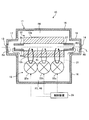
- FIG. 1 is a sectional view showing a configuration of a gas laser oscillator according to Embodiment 1 of the present invention.
- 2 is a cross-sectional view taken along the line II-II in FIG. 1, showing the configuration of the laser gas circulating means.
- the gas laser oscillator 10 includes a gas sealing unit 11, a discharge excitation unit 12, a partial reflection mirror 13, a total reflection mirror 14, a laser gas circulation unit 15, ducts 26 and 27, and a control device 29.
- the partial reflection mirror 13 and the total reflection mirror 14 serve as reflection means for reflecting a laser generated from the discharge-excited laser gas.
- the gas sealing means 11 is sealed with laser gas.
- the gas sealing means 11 is a container in which a mechanism for oscillating a laser is arranged, and the laser passes on the optical axis L.
- the optical axis L is basically a straight line.
- the gas sealing means 11 includes a housing 16 and a first mirror case 17 and a second mirror case 18.
- the first mirror case 17 and the second mirror case 18 are side casings connected to both side surfaces of the casing 16 orthogonal to the optical axis L of the laser.
- the casing 16 has a discharge excitation means 12 and a laser gas circulation means 15 disposed therein.
- the first mirror case 17 is inserted into an opening formed on one side surface of the housing 16 on the optical axis L of the laser gas, and the internal space is connected.
- the second mirror case 18 is inserted into an opening formed on the other side surface of the housing 16 on the optical axis L of the laser gas, and the internal space is connected.
- the casing 16 and the first mirror case 17 and the second mirror case 18 are connected via a sealing member such as an O-ring.
- a sealing member such as an O-ring.
- the connection part of the housing 16, the first mirror case 17, and the second mirror case 18 is airtight, and the inside is a sealed space.
- the discharge excitation means 12 excites the laser gas.
- the discharge excitation means 12 has a pair of discharge electrodes 12a and 12b.
- the pair of discharge electrodes 12 a and 12 b are arranged inside the housing 16, that is, in a sealed space of the gas sealing means 11.
- the pair of discharge electrodes 12a and 12b are disposed at positions facing each other with the optical axis L interposed therebetween.
- the discharge excitation means 12 applies a voltage to the pair of discharge electrodes 12a and 12b, thereby discharging and exciting a laser gas in a region sandwiched between the pair of discharge electrodes 12a and 12b to oscillate the laser.
- a region sandwiched between the pair of discharge electrodes 12a and 12b is a discharge excitation region R1.
- a region other than the discharge excitation region R1 in the gas sealing unit 11 is a non-excitation region where the laser gas is not excited by discharge. Details of the non-excitation region will be described later.
- the partial reflecting mirror 13 is provided on the optical axis L of the laser of the first mirror case 17.
- the partial reflecting mirror 13 moves on the optical axis L, transmits part of the laser that has reached, and reflects part of it.
- the total reflection mirror 14 is provided on the laser optical axis L of the second mirror case 18.
- the total reflection mirror 14 moves on the optical axis L and reflects the reached laser.
- the partial reflection mirror 13 and the total reflection mirror 14 are provided at both ends of the gas sealing means 11 in the optical axis L direction.
- the gas laser oscillator 10 amplifies a laser moving on the optical axis L while reflecting it between the partial reflection mirror 13 and the total reflection mirror 14 and oscillates it from the partial reflection mirror 13 side.
- the laser gas circulation means 15 includes a heat exchanger 21, three blowers 22 a, 22 b, 22 c that circulate laser gas inside the gas sealing means 11, and a guide 25.
- the heat exchanger 21 is arranged in a region overlapping with a region where the discharge excitation means 12 is arranged in a direction parallel to the optical axis L.
- the heat exchanger 21 cools the passing laser gas.
- the heat exchanger 21 can use various heat exchange mechanisms such as water cooling or air cooling.
- the three blowers 22a, 22b, and 22c are arranged in a row in the direction of the optical axis L.
- the three blowers 22a, 22b, and 22c are arranged in a region overlapping with a region where the discharge excitation means 12 is arranged in a direction parallel to the optical axis L.
- the blowers 22a, 22b, and 22c are devices that generate a flow in the laser gas as the fan rotates.
- the air blowers 22a, 22b, and 22c face each other at the suction port 23 and the air outlet 24, suck a part of the laser gas cooled by the heat exchanger 21 from the air suction port 23, and blow the sucked laser gas into the air outlet. Blow out from 24.
- the guide 25 is a plate-like member whose one end is in contact with the discharge electrodes 12 a and 12 b and whose other end is in contact with the heat exchanger 21.
- the guide 25 connects the discharge excitation region R1 sandwiched between the discharge electrode 12a and the discharge electrode 12b and the region where the heat exchanger 21 is disposed.
- the guide 25 only needs to have a shape that can regulate and guide the path through which the laser gas flows, and does not have to be in contact with the discharge electrodes 12 a and 12 b and the heat exchanger 21.
- a heat exchanger 21 and blowers 22a, 22b, and 22c are arranged in a region included in the discharge excitation region R1 in a direction parallel to the optical axis L.
- the heat exchanger 21 and the blowers 22a, 22b, and 22c are arranged at different positions on the surface orthogonal to the optical axis L, as shown in FIG.
- the laser gas circulating means 15 drives the blowers 22a, 22b, and 22c to form a flow of laser gas from the blowers 22a, 22b, and 22c toward the discharge excitation region R1 on a surface orthogonal to the optical axis L.
- the laser gas circulation means 15 drives the blowers 22a, 22b, and 22c, so that the laser gas in the discharge excitation region R1 passes through the guide 25 and flows into the heat exchanger 21, and then flows into the blowers 22a, 22b, and 22c. A flow of laser gas is formed.
- the duct (first duct) 26 is disposed between the discharge electrodes 12 a and 12 b and the partial reflection mirror 13.
- the duct 26 has a cylindrical shape surrounding the periphery of the optical axis L, one end of the cylindrical shape is in contact with the discharge electrodes 12a and 12b, and the other end is open. That is, the other end of the duct 26 is separated from the partial reflecting mirror 13, and a gap is left in the direction of the optical axis L.
- the duct (second duct) 27 is disposed between the discharge electrodes 12 a and 12 b and the total reflection mirror 14.
- the duct 27 has a cylindrical shape surrounding the periphery of the optical axis L. One end of the cylindrical shape is in contact with the discharge electrodes 12a and 12b, and the other end is open. In other words, the other end of the duct 27 is separated from the total reflection mirror 14, and there is a gap in the optical axis L direction.
- the control device 29 controls the operation of the discharge excitation means 12 and the laser gas circulation means 15 to control laser oscillation and laser gas circulation.
- the control device 29 may be a system LSI (Large Scale Integral circuit) or a device combining a plurality of electronic circuits.
- the control device 29 includes a processor, a memory, and an input / output device having an input / output port and an input / output interface circuit, and controls the operations of the discharge excitation means 12 and the laser gas circulation means 15 stored in the memory.
- the processor may execute a program for controlling.
- non-excitation region will be described as non-excitation regions R2 to R8 as follows.
- a region inside the duct 26 located closer to the first mirror case 17 than the discharge excitation region R1 is defined as a non-excitation region R2.
- a region inside the duct 27 that is closer to the second mirror case 18 than the discharge excitation region R1 is defined as a non-excitation region R3.
- a region outside the duct 26 in the first mirror case 17 is a non-excitation region R4.
- a region outside the duct 27 in the second mirror case 18 is defined as a non-excitation region R5.
- a region between the discharge electrode 12a and the housing 16 is defined as a non-excitation region R6.
- the discharge excitation region R1 and the fans 22a, 22b, and 22c are set as a non-excitation region R7, and the region on the opposite side to the heat exchanger 21, that is, the region on the outlet 24 side is set as a non-excitation region. R8.
- the gas laser oscillator 10 includes a non-excitation region R4, a non-excitation region R2, a discharge excitation region R1, a non-excitation region R3, and a non-excitation region on the optical axis L from the first mirror case 17 side toward the second mirror case 18 side. Arranged in the order of R5.
- the gas laser oscillator 10 oscillates a laser by discharging and exciting the laser gas in the discharge excitation region R1 by the discharge excitation means 12, and reciprocally reflects between the partial reflection mirror 13 and the total reflection mirror 14 while By outputting a part of the laser, the laser is output outside the gas sealing means 11.
- the gas laser oscillator 10 circulates the laser gas in the gas sealing means 11 by the laser gas circulation means 15.
- the laser gas circulation means 15 drives the blowers 22a, 22b, and 22c, so that the laser gas flows in the order of the discharge excitation region R1, the non-excitation region R7, and the non-excitation region R8.
- the laser gas in the discharge excitation region R1 flows into the heat exchanger 21 and is cooled, and then passes through the blowers 22a, 22b, and 22c and flows into the discharge excitation region R1.
- the laser gas heated by the laser in the discharge excitation region R1 is cooled by the heat exchanger 21.
- the laser gas flowing into the discharge excitation region R1 becomes the laser gas cooled by the heat exchanger 21.
- a part of the laser gas sent out from the blowers 22a, 22b, and 22c also flows into the non-excitation region R6.
- the gas laser oscillator 10 forms a flow in which the laser gas flows in the order of the discharge excitation region R1, the non-excitation region R7, and the non-excitation region R8 by the laser gas circulation means 15.
- the discharge excitation region R1, the non-excitation region R7, and the non-excitation region are provided in the non-excitation region R4 and the non-excitation region R5.
- a flow similar to R8 is not formed.
- a pressure difference is generated between the discharge excitation region R1 in which the laser gas is circulated and the non-excitation region R4 and the non-excitation region R5 in which the laser gas is not circulated.
- the gas laser oscillator 10 generates a flow of laser gas from a position where the pressure is high to a position where the pressure is low due to the pressure difference, and between the discharge excitation region R1 and the non-excitation region R4, the non-excitation region R4 and the non-excitation region R2. Then, a flow of laser gas in the direction of the discharge excitation region R1 occurs. That is, a laser gas flow from the non-excitation region R4 to the discharge excitation region R1 is generated in the first duct 26. Similarly, in the gas laser oscillator 10, a laser gas flow in the direction of the non-excitation region R5, the non-excitation region R3, and the discharge excitation region R1 occurs between the discharge excitation region R1 and the non-excitation region R5. That is, a laser gas flow from the non-excitation region R5 toward the discharge excitation region R1 is generated in the second duct 27.
- the gas laser oscillator 10 forms a flow toward the discharge excitation region R1 in the ducts 26 and 27, so that the laser gas on the path through which the laser in the non-excitation regions R2 and R3 passes flows into the discharge excitation region R1. Then, it flows into the heat exchanger 21 with the flow of the circulating laser gas. Further, the gas laser oscillator 10 can cause the laser gas cooled by the non-excitation regions R2, R3, R4, and R5 to flow into the ducts 26 and 27 by forming a flow toward the discharge excitation region R1.
- the gas laser oscillator 10 uses the guide 25 as a pipe line connecting the discharge excitation region R1 and the heat exchanger 21, so that the laser gas after passing through the heat exchanger 21 is converted into the non-excitation regions R2, R3, R4, R5.
- the laser gas cooled by can be introduced.
- the gas laser oscillator 10 can supply a cooled laser gas on the optical axis L, and can flow the laser gas on the optical axis L toward the heat exchanger 21. Thereby, the temperature rise of the laser gas on the optical axis L can be suppressed, and the laser can be generated efficiently. Moreover, the gas laser oscillator 10 arrange
- the flow of the laser gas toward the discharge excitation region R1 is formed in the non-excitation regions R2, R3, R4, and R5.
- an air blower can be decreased and the air volume by an air blower can be decreased.
- the gas laser oscillator 10 can suppress heating of the laser gas while suppressing power consumption. Further, the gas laser oscillator 10 can suppress heating of the laser gas, thereby suppressing power consumption and stabilizing the output of the laser gas.
- FIG. 9 is a distribution diagram of the laser gas flow velocity in the discharge excitation region according to the first embodiment and later-described second, third, and fourth embodiments. Further, as a method for improving the effect of suppressing the heating of the laser gas, in the discharge excitation region R1, by creating a distribution in which the flow velocity of the laser gas in the region close to the non-excitation regions R2 and R3 as shown in FIG. The flow of the laser gas from the position where the pressure is high to the position where the pressure is low, that is, between the discharge excitation region R1 and the non-excitation region R4, the discharge excitation in the direction of the non-excitation region R4, the non-excitation region R2, and the discharge excitation region R1.
- the gas laser oscillator 10 is not provided with a large volume blower along the non-excitation region R4 and the non-excitation region R5, the volume of the first mirror case 17 and the second mirror case 18 of the gas laser oscillator 10 is reduced. It can be made smaller and the usability can be improved.
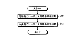
- FIG. 3 is a flowchart for explaining the starting order of the gas laser oscillator 10 according to the first embodiment of the present invention.
- 4 and 5 are cross-sectional views for explaining the operation of the gas laser oscillator according to the first embodiment of the present invention.
- the start timing of the blowers 22 a, 22 b, and 22 c be adjusted under the control of the control device 29.
- the control device 29 first activates the blower on the end side (the side close to the ducts 26 and 27) of the discharge excitation region R1 in the direction of the optical axis L, in this embodiment, the blowers 22a and 22c, and the direction of the optical axis L.
- the blower on the center side of the discharge excitation region R1, in this embodiment, the blower 22b is activated later.
- the control device 29 activates the blowers 22a and 22c that blow the laser gas to both ends of the discharge excitation region R1 (step S10).
- the flow flows through the discharge excitation region R1 and the non-excitation regions R7 and R8 on the side closer to the non-excitation regions R4 and R5 where the fans 22a and 22c are arranged. Is formed.
- the controller 29 activates the blower 22b that blows the laser gas toward the center of the discharge excitation region R1 after the set time has elapsed since the blowers 22a and 22c are activated (step S12).
- the set time is set in advance by the operator.
- a flow of circulating the laser gas is formed in all of the blowers 22a, 22b, and 22c.
- the gas laser oscillator 10 divides the activation of the blowers 22a, 22b, and 22c into two steps, thereby discharging discharge on the position side connected to the non-excitation regions R4 and R5 via the non-excitation regions R2 and R3 in the optical axis L direction.
- a larger laser gas flow can be formed in the region R1.
- the flow rate of the laser gas in the discharge excitation region R1 has a distribution as shown in FIG. Thereby, a larger pressure difference is generated between the discharge excitation region R1 and the non-excitation region R4, and the flow of the laser gas from the non-excitation region R4 toward the discharge excitation region R1 becomes faster.
- the laser gas cooled on the optical axis L can be more efficiently supplied without increasing the driving force for circulating the laser gas, and the heated laser gas can be efficiently supplied to the heat exchanger 21. Can do. As described above, it is possible to stabilize the output of the laser while suppressing power consumption.
- control device 29 functions as a gas flow control means for controlling the flow of the laser gas from the non-excitation regions R2 to R8 to the discharge excitation region R1 by individually controlling the fans 22a, 22b, and 22c.
- control device 29 can intentionally create a larger flow of laser gas from the non-excitation regions R2 to R8 toward the discharge excitation region R1.
- the number of blowers is three, but the number may be more than three.
- the two laser gas circulating means at both ends may be set as both end sides, and the two laser gas circulating means at the center may be set as the central side to be activated separately.
- the number of blowers may be more than three in the embodiments described later.
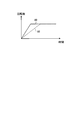
- FIG. FIG. 6 is a graph for explaining the operation of the gas laser oscillator according to the second embodiment of the present invention.
- the gas laser oscillator 10 may cause a difference in the starting times of the blowers 22a, 22b, and 22c.
- the control device 29 determines the start time of the blower 22a, 22c in the direction of the optical axis L in the direction of the optical axis L, in the direction of the optical axis L.
- the blower on the center side of the discharge excitation region R1 in this embodiment, is shorter than the start-up time of the blower 22b.
- the control device 29 sets the relationship between the time and the rotational speed of the blowers 22a and 22c as a line 80, and sets the relationship between the time and the rotational speed of the blower 22b as a line 82,
- the starting time of 22c that is, the time taken to reach the set rotational speed is made shorter than the starting time of the blower 22b.
- the gas laser oscillator 10 sets the non-excitation regions R2 and R3 in the direction of the optical axis L by increasing the rotational speed of the blowers 22a and 22c earlier than the blower 22b by setting the start times of the blowers 22a, 22b and 22c to different times.
- a larger laser gas flow can be formed in the discharge excitation region R1 on the position side connected to the non-excitation regions R4 and R5.
- the flow rate of the laser gas in the discharge excitation region R1 has a distribution as shown in FIG. Thereby, a larger pressure difference is generated between the discharge excitation region R1 and the non-excitation region R4, and the flow of the laser gas from the non-excitation region R4 toward the discharge excitation region R1 becomes faster.
- the laser gas cooled on the optical axis L can be more efficiently supplied without increasing the driving force for circulating the laser gas, and the heated laser gas can be efficiently supplied to the heat exchanger 21. Can do. As described above, it is possible to stabilize the output of the laser while suppressing power consumption.
- a difference is caused in the start-up time to reach the set rotation speed under the control of the control device 29, but the present invention is not limited to this.
- a difference may be caused in the start-up time to reach the set rotation speed with the design values of the blowers 22 a, 22 b, and 22 c.
- the blowers 22a and 22c and the blower 22b may be different blowers, and even if the same control value is input, the blowers 22a and 22c may reach the rotational speed set earlier than the blower 22b.
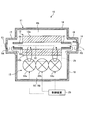
- FIG. 7 is a sectional view showing the configuration of the gas laser oscillator according to the third embodiment of the present invention.
- the gas laser oscillator 10 may cause a difference between the rotational speeds of the blowers 22a, 22b, and 22c and the rotational speed during steady operation.
- the control device 29 determines the number of rotations of the blower 22a, 22c in the direction of the optical axis L in the direction of the optical axis L in the direction of the optical axis L.
- the rotational speed of the blower 22b in the center of the discharge excitation region R1, that is, the blower 22b in this embodiment is made larger.
- the gas laser oscillator 10 sets the rotational speeds of the blowers 22a, 22b, and 22c to different values, and makes the rotational speeds of the blowers 22a and 22c larger than the rotational speed of the blower 22b, as shown in FIG. ,
- a larger laser gas flow can be formed in the discharge excitation region R1 on the position side connected to the non-excitation regions R4 and R5 via the non-excitation regions R2 and R3.
- the flow rate of the laser gas in the discharge excitation region R1 has a distribution as shown in FIG. Thereby, a larger pressure difference is generated between the discharge excitation region R1 and the non-excitation region R4, and the flow of the laser gas from the non-excitation region R4 toward the discharge excitation region R1 becomes faster.
- the laser gas cooled on the optical axis L can be more efficiently supplied without increasing the driving force for circulating the laser gas, and the heated laser gas can be efficiently supplied to the heat exchanger 21. Can do. As described above, it is possible to stabilize the output of the laser while suppressing power consumption.
- the set rotational speed difference may be generated with the design values of the blowers 22a, 22b, and 22c. That is, even if the blowers 22a and 22c and the blower 22b are different blowers and the same control value is input, the rotation speed of the blowers 22a and 22c may be larger than the rotation speed of the blower 22b.
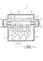
- FIG. FIG. 8 is a cross-sectional view showing a configuration of a gas laser oscillator according to Embodiment 4 of the present invention.
- the laser gas circulating means 15a of the gas laser oscillator 10a has blowers 22a, 22c and 92.
- the blower 92 is disposed at the position of the blower 22 b of the gas laser oscillator 10.
- the air blower 92 has a smaller flow rate (air flow rate) during steady operation than the air blowers 22a and 22c.
- the air volume of the blowers 22a and 22c on the end side of the discharge excitation region R1 in the direction of the optical axis L is the center side of the discharge excitation region R1 in the direction of the optical axis L.
- the blower which is larger than the air volume of the blower 92 in this embodiment.
- the gas laser oscillator 10a makes the airflows of the blowers 22a, 22c, and 92 different from each other and makes the airflows of the blowers 22a and 22c larger than the airflow of the blower 92.
- a larger laser gas flow can be formed in the discharge excitation region R1 on the position side connected to the non-excitation regions R4 and R5 via the excitation regions R2 and R3.
- the flow rate of the laser gas in the discharge excitation region R1 has a distribution as shown in FIG. Thereby, a larger pressure difference is generated between the discharge excitation region R1 and the non-excitation region R4, and the flow of the laser gas from the non-excitation region R4 toward the discharge excitation region R1 becomes faster.
- the laser gas cooled on the optical axis L can be more efficiently supplied without increasing the driving force for circulating the laser gas, and the heated laser gas can be efficiently supplied to the heat exchanger 21. Can do. As described above, it is possible to stabilize the output of the laser while suppressing power consumption.
- the difference in the air volume is caused by the characteristics of the blower.
- the difference in the air volume may be caused by the control of the control device 29.
- the configuration shown in the above embodiment shows an example of the contents of the present invention, and can be combined with other known techniques, and each embodiment can be implemented without departing from the gist of the present invention.
- the forms may be combined, and a part of the configuration may be omitted or changed.
Landscapes
- Physics & Mathematics (AREA)
- Electromagnetism (AREA)
- Engineering & Computer Science (AREA)
- Plasma & Fusion (AREA)
- Optics & Photonics (AREA)
- Lasers (AREA)
Abstract
La présente invention porte sur un oscillateur laser à gaz (10) qui comporte ce qui suit : un moyen d'étanchéité aux gaz (11) ; un moyen d'excitation de décharge (12) ; un miroir à réflexion partielle (13) ; un miroir à réflexion complète (14) ; un moyen de circulation de gaz laser (15) ; des conduits (26, 27) ; et un dispositif de commande (29). Le moyen de circulation de gaz laser (15) a un échangeur de chaleur (21), trois ventilateurs de soufflage (22a, 22b, 22c) destinés à faire circuler le gaz laser, et un guide (25), et crée un écoulement de gaz laser tout en refroidissant le gaz laser passant à travers ce dernier. L'oscillateur laser à gaz (10) crée un écoulement à l'intérieur des conduits (26, 27) qui est dirigé vers une région d'excitation de décharge (R1), ce qui provoque un afflux du gaz laser, qui a été refroidi au moyen de régions de non-excitation (R2, R3, R4, et R5), et l'accélération de cet écoulement stabilise la sortie de laser.
Priority Applications (1)
| Application Number | Priority Date | Filing Date | Title |
|---|---|---|---|
| PCT/JP2015/063678 WO2016181511A1 (fr) | 2015-05-12 | 2015-05-12 | Oscillateur laser à gaz |
Applications Claiming Priority (1)
| Application Number | Priority Date | Filing Date | Title |
|---|---|---|---|
| PCT/JP2015/063678 WO2016181511A1 (fr) | 2015-05-12 | 2015-05-12 | Oscillateur laser à gaz |
Publications (1)
| Publication Number | Publication Date |
|---|---|
| WO2016181511A1 true WO2016181511A1 (fr) | 2016-11-17 |
Family
ID=57248171
Family Applications (1)
| Application Number | Title | Priority Date | Filing Date |
|---|---|---|---|
| PCT/JP2015/063678 Ceased WO2016181511A1 (fr) | 2015-05-12 | 2015-05-12 | Oscillateur laser à gaz |
Country Status (1)
| Country | Link |
|---|---|
| WO (1) | WO2016181511A1 (fr) |
Citations (5)
| Publication number | Priority date | Publication date | Assignee | Title |
|---|---|---|---|---|
| JPS60254683A (ja) * | 1984-05-31 | 1985-12-16 | Mitsubishi Electric Corp | レ−ザ−発振装置 |
| JPS632393A (ja) * | 1986-06-23 | 1988-01-07 | Toshiba Corp | ガスレ−ザ発振装置 |
| JPH02192782A (ja) * | 1989-01-20 | 1990-07-30 | Mitsubishi Electric Corp | レーザ発振器 |
| JPH06140692A (ja) * | 1992-10-28 | 1994-05-20 | Mitsubishi Electric Corp | レーザ発振器 |
| JPH07131090A (ja) * | 1993-10-29 | 1995-05-19 | Toshiba Corp | レーザ発振器 |
-
2015
- 2015-05-12 WO PCT/JP2015/063678 patent/WO2016181511A1/fr not_active Ceased
Patent Citations (5)
| Publication number | Priority date | Publication date | Assignee | Title |
|---|---|---|---|---|
| JPS60254683A (ja) * | 1984-05-31 | 1985-12-16 | Mitsubishi Electric Corp | レ−ザ−発振装置 |
| JPS632393A (ja) * | 1986-06-23 | 1988-01-07 | Toshiba Corp | ガスレ−ザ発振装置 |
| JPH02192782A (ja) * | 1989-01-20 | 1990-07-30 | Mitsubishi Electric Corp | レーザ発振器 |
| JPH06140692A (ja) * | 1992-10-28 | 1994-05-20 | Mitsubishi Electric Corp | レーザ発振器 |
| JPH07131090A (ja) * | 1993-10-29 | 1995-05-19 | Toshiba Corp | レーザ発振器 |
Similar Documents
| Publication | Publication Date | Title |
|---|---|---|
| JP4782887B1 (ja) | ガスレーザ装置 | |
| JP2017005141A (ja) | レーザ発振部、空気冷却機、および除湿器を共通の冷却水にて冷却するレーザ装置 | |
| KR20140017924A (ko) | 터보 블로워장치 | |
| JP6145122B2 (ja) | 温度調整が可能なガスレーザ発振器 | |
| JP5786656B2 (ja) | 電子機器及び電子機器の冷却方法 | |
| WO2016181511A1 (fr) | Oscillateur laser à gaz | |
| CN109643047B (zh) | 图像投影装置 | |
| CN105870765B (zh) | 具备冷却共振器部的风扇的激光振荡器 | |
| US20160336706A1 (en) | Gas laser oscillation device | |
| JP7216558B2 (ja) | 車両用灯具 | |
| JP7392589B2 (ja) | 光源装置 | |
| JPWO2015107570A1 (ja) | ガスレーザ発振装置、ガスレーザ発振方法およびガスレーザ加工機 | |
| JP2011228461A (ja) | 冷却装置および電子機器 | |
| JP2007316334A (ja) | プロジェクタ | |
| KR101823806B1 (ko) | 직교 여기형 가스 레이저 발진 장치 | |
| JP6010152B2 (ja) | 送風機を備えるレーザ発振器 | |
| US10508803B2 (en) | Synthetic jets to cool digital micromirror devices | |
| JP2011099991A (ja) | 投射型表示装置 | |
| JP2013235718A (ja) | 紫外線照射装置 | |
| JP5823444B2 (ja) | 電子機器 | |
| JP4444472B2 (ja) | リフローはんだ付け方法とその装置 | |
| JP2015068298A (ja) | 送風装置 | |
| TW201445051A (zh) | 散熱系統 | |
| JP7702367B2 (ja) | オゾン発生装置 | |
| JP2011118152A (ja) | 投射型表示装置 |
Legal Events
| Date | Code | Title | Description |
|---|---|---|---|
| 121 | Ep: the epo has been informed by wipo that ep was designated in this application |
Ref document number: 15891835 Country of ref document: EP Kind code of ref document: A1 |
|
| NENP | Non-entry into the national phase |
Ref country code: DE |
|
| 122 | Ep: pct application non-entry in european phase |
Ref document number: 15891835 Country of ref document: EP Kind code of ref document: A1 |
|
| NENP | Non-entry into the national phase |
Ref country code: JP |