WO2016203836A1 - 空気入りタイヤ - Google Patents
空気入りタイヤ Download PDFInfo
- Publication number
- WO2016203836A1 WO2016203836A1 PCT/JP2016/062436 JP2016062436W WO2016203836A1 WO 2016203836 A1 WO2016203836 A1 WO 2016203836A1 JP 2016062436 W JP2016062436 W JP 2016062436W WO 2016203836 A1 WO2016203836 A1 WO 2016203836A1
- Authority
- WO
- WIPO (PCT)
- Prior art keywords
- groove
- side wall
- tire
- tread
- pneumatic tire
- Prior art date
- Legal status (The legal status is an assumption and is not a legal conclusion. Google has not performed a legal analysis and makes no representation as to the accuracy of the status listed.)
- Ceased
Links
Images






Classifications
-
- B—PERFORMING OPERATIONS; TRANSPORTING
- B60—VEHICLES IN GENERAL
- B60C—VEHICLE TYRES; TYRE INFLATION; TYRE CHANGING; CONNECTING VALVES TO INFLATABLE ELASTIC BODIES IN GENERAL; DEVICES OR ARRANGEMENTS RELATED TO TYRES
- B60C11/00—Tyre tread bands; Tread patterns; Anti-skid inserts
- B60C11/03—Tread patterns
- B60C11/0311—Patterns comprising tread lugs arranged parallel or oblique to the axis of rotation
- B60C11/0316—Patterns comprising tread lugs arranged parallel or oblique to the axis of rotation further characterised by the groove cross-section
-
- B—PERFORMING OPERATIONS; TRANSPORTING
- B60—VEHICLES IN GENERAL
- B60C—VEHICLE TYRES; TYRE INFLATION; TYRE CHANGING; CONNECTING VALVES TO INFLATABLE ELASTIC BODIES IN GENERAL; DEVICES OR ARRANGEMENTS RELATED TO TYRES
- B60C11/00—Tyre tread bands; Tread patterns; Anti-skid inserts
- B60C11/03—Tread patterns
- B60C11/12—Tread patterns characterised by the use of narrow slits or incisions, e.g. sipes
- B60C11/1236—Tread patterns characterised by the use of narrow slits or incisions, e.g. sipes with special arrangements in the tread pattern
- B60C11/124—Tread patterns characterised by the use of narrow slits or incisions, e.g. sipes with special arrangements in the tread pattern inclined with regard to a plane normal to the tread surface
-
- B—PERFORMING OPERATIONS; TRANSPORTING
- B60—VEHICLES IN GENERAL
- B60C—VEHICLE TYRES; TYRE INFLATION; TYRE CHANGING; CONNECTING VALVES TO INFLATABLE ELASTIC BODIES IN GENERAL; DEVICES OR ARRANGEMENTS RELATED TO TYRES
- B60C11/00—Tyre tread bands; Tread patterns; Anti-skid inserts
- B60C11/03—Tread patterns
- B60C11/0302—Tread patterns directional pattern, i.e. with main rolling direction
-
- B—PERFORMING OPERATIONS; TRANSPORTING
- B60—VEHICLES IN GENERAL
- B60C—VEHICLE TYRES; TYRE INFLATION; TYRE CHANGING; CONNECTING VALVES TO INFLATABLE ELASTIC BODIES IN GENERAL; DEVICES OR ARRANGEMENTS RELATED TO TYRES
- B60C11/00—Tyre tread bands; Tread patterns; Anti-skid inserts
- B60C11/03—Tread patterns
- B60C11/0306—Patterns comprising block rows or discontinuous ribs
- B60C11/0309—Patterns comprising block rows or discontinuous ribs further characterised by the groove cross-section
-
- B—PERFORMING OPERATIONS; TRANSPORTING
- B60—VEHICLES IN GENERAL
- B60C—VEHICLE TYRES; TYRE INFLATION; TYRE CHANGING; CONNECTING VALVES TO INFLATABLE ELASTIC BODIES IN GENERAL; DEVICES OR ARRANGEMENTS RELATED TO TYRES
- B60C11/00—Tyre tread bands; Tread patterns; Anti-skid inserts
- B60C11/03—Tread patterns
- B60C11/12—Tread patterns characterised by the use of narrow slits or incisions, e.g. sipes
- B60C11/1204—Tread patterns characterised by the use of narrow slits or incisions, e.g. sipes with special shape of the sipe
-
- B—PERFORMING OPERATIONS; TRANSPORTING
- B60—VEHICLES IN GENERAL
- B60C—VEHICLE TYRES; TYRE INFLATION; TYRE CHANGING; CONNECTING VALVES TO INFLATABLE ELASTIC BODIES IN GENERAL; DEVICES OR ARRANGEMENTS RELATED TO TYRES
- B60C11/00—Tyre tread bands; Tread patterns; Anti-skid inserts
- B60C11/03—Tread patterns
- B60C11/12—Tread patterns characterised by the use of narrow slits or incisions, e.g. sipes
- B60C11/1259—Depth of the sipe
-
- B—PERFORMING OPERATIONS; TRANSPORTING
- B60—VEHICLES IN GENERAL
- B60C—VEHICLE TYRES; TYRE INFLATION; TYRE CHANGING; CONNECTING VALVES TO INFLATABLE ELASTIC BODIES IN GENERAL; DEVICES OR ARRANGEMENTS RELATED TO TYRES
- B60C11/00—Tyre tread bands; Tread patterns; Anti-skid inserts
- B60C11/03—Tread patterns
- B60C11/12—Tread patterns characterised by the use of narrow slits or incisions, e.g. sipes
- B60C11/1272—Width of the sipe
-
- B—PERFORMING OPERATIONS; TRANSPORTING
- B60—VEHICLES IN GENERAL
- B60C—VEHICLE TYRES; TYRE INFLATION; TYRE CHANGING; CONNECTING VALVES TO INFLATABLE ELASTIC BODIES IN GENERAL; DEVICES OR ARRANGEMENTS RELATED TO TYRES
- B60C11/00—Tyre tread bands; Tread patterns; Anti-skid inserts
- B60C11/03—Tread patterns
- B60C11/13—Tread patterns characterised by the groove cross-section, e.g. for buttressing or preventing stone-trapping
- B60C11/1307—Tread patterns characterised by the groove cross-section, e.g. for buttressing or preventing stone-trapping with special features of the groove walls
-
- B—PERFORMING OPERATIONS; TRANSPORTING
- B60—VEHICLES IN GENERAL
- B60C—VEHICLE TYRES; TYRE INFLATION; TYRE CHANGING; CONNECTING VALVES TO INFLATABLE ELASTIC BODIES IN GENERAL; DEVICES OR ARRANGEMENTS RELATED TO TYRES
- B60C11/00—Tyre tread bands; Tread patterns; Anti-skid inserts
- B60C11/03—Tread patterns
- B60C11/13—Tread patterns characterised by the groove cross-section, e.g. for buttressing or preventing stone-trapping
- B60C11/1307—Tread patterns characterised by the groove cross-section, e.g. for buttressing or preventing stone-trapping with special features of the groove walls
- B60C11/1315—Tread patterns characterised by the groove cross-section, e.g. for buttressing or preventing stone-trapping with special features of the groove walls having variable inclination angles, e.g. warped groove walls
-
- B—PERFORMING OPERATIONS; TRANSPORTING
- B60—VEHICLES IN GENERAL
- B60C—VEHICLE TYRES; TYRE INFLATION; TYRE CHANGING; CONNECTING VALVES TO INFLATABLE ELASTIC BODIES IN GENERAL; DEVICES OR ARRANGEMENTS RELATED TO TYRES
- B60C11/00—Tyre tread bands; Tread patterns; Anti-skid inserts
- B60C11/03—Tread patterns
- B60C11/13—Tread patterns characterised by the groove cross-section, e.g. for buttressing or preventing stone-trapping
- B60C11/1307—Tread patterns characterised by the groove cross-section, e.g. for buttressing or preventing stone-trapping with special features of the groove walls
- B60C11/1323—Tread patterns characterised by the groove cross-section, e.g. for buttressing or preventing stone-trapping with special features of the groove walls asymmetric
-
- B—PERFORMING OPERATIONS; TRANSPORTING
- B60—VEHICLES IN GENERAL
- B60C—VEHICLE TYRES; TYRE INFLATION; TYRE CHANGING; CONNECTING VALVES TO INFLATABLE ELASTIC BODIES IN GENERAL; DEVICES OR ARRANGEMENTS RELATED TO TYRES
- B60C11/00—Tyre tread bands; Tread patterns; Anti-skid inserts
- B60C11/03—Tread patterns
- B60C11/0311—Patterns comprising tread lugs arranged parallel or oblique to the axis of rotation
- B60C2011/0313—Patterns comprising tread lugs arranged parallel or oblique to the axis of rotation directional type
-
- B—PERFORMING OPERATIONS; TRANSPORTING
- B60—VEHICLES IN GENERAL
- B60C—VEHICLE TYRES; TYRE INFLATION; TYRE CHANGING; CONNECTING VALVES TO INFLATABLE ELASTIC BODIES IN GENERAL; DEVICES OR ARRANGEMENTS RELATED TO TYRES
- B60C11/00—Tyre tread bands; Tread patterns; Anti-skid inserts
- B60C11/03—Tread patterns
- B60C11/12—Tread patterns characterised by the use of narrow slits or incisions, e.g. sipes
- B60C11/1204—Tread patterns characterised by the use of narrow slits or incisions, e.g. sipes with special shape of the sipe
- B60C2011/1213—Tread patterns characterised by the use of narrow slits or incisions, e.g. sipes with special shape of the sipe sinusoidal or zigzag at the tread surface
Definitions
- the present invention relates to a pneumatic tire.
- the rigidity of the land part cannot be increased by reducing the negative rate of the tread pattern due to the balance with other performance, there is a method to increase the rigidity of the land part by inclining the groove side wall. Since the volume is reduced and the drainage performance is lowered, the hydroplaning performance is lowered. Further, when the volume of the groove is reduced, the groove becomes thinner and the amount of rubber is relatively increased, which leads to deterioration of rolling resistance. On the other hand, if the groove side wall is made perpendicular to the tread surface and the volume of the groove is increased, the rigidity of the land portion partitioned by the groove is lowered. For this reason, it is difficult to achieve a high degree of compatibility between wet performance and steering stability performance when traveling on a dry road surface.
- One embodiment of the present invention is intended to solve the above-described problem, and an object thereof is to provide a pneumatic tire that enables a high degree of compatibility between wet performance and steering stability performance when traveling on a dry road surface. To do.
- a pneumatic tire includes: a tread that contacts a road surface; and a plurality of grooves that are provided on the tread and that divide a land portion.
- the pneumatic tire has a groove depth of 1 from a tread surface of the tread.
- the groove side wall up to the groove depth of / 2 is defined as the first groove side wall
- the groove side wall from the groove depth 1 ⁇ 2 of the groove depth to the deepest part of the groove bottom is defined as the second groove side wall, and orthogonal to the longitudinal direction of the groove.
- the groove side wall from the tread surface of the groove to the groove depth 1 ⁇ 2 of the groove depth is the first groove side wall, and the groove side wall from the groove depth 1 ⁇ 2 of the groove depth to the deepest part of the groove bottom is formed.
- the first imaginary line passing through the end of the first groove side wall on the tread surface side and perpendicular to the tread surface when viewed in a cross section orthogonal to the longitudinal direction of the groove, and the groove bottom side of the first groove side wall The area of the region surrounded by the second imaginary line orthogonal to the first imaginary line and the first groove side wall is A, and when viewed in a cross section orthogonal to the longitudinal direction of the groove, A region surrounded by the third imaginary line passing through the end of the groove bottom side of the groove side wall and perpendicular to the tread surface, the fourth imaginary line passing through the deepest part of the groove bottom and parallel to the tread surface, and the second groove side wall
- the area is B
- the relationship between the area A and the area B is A ⁇ B, so that the rigidity of the land portion is ensured while ensuring the volume of the groove, and the rigidity of the land portion on the groove bottom side.
- the pneumatic tire according to the first aspect is defined by the pneumatic tire being mounted on a standard rim defined in JATMA YEAR BOOK (Japan Automobile Tire Association Standard), and applicable size and ply rating in JATMA YEAR BOOK.
- JATMA YEAR BOOK Joint Automobile Tire Association Standard
- JATMA YEAR BOOK Joint Automobile Tire Association Standard
- maximum load capacity internal pressure-load capacity correspondence table in bold
- the ratio B / A between the area B and the area A is set to 120% or more.
- the pneumatic tire according to the third aspect is the pneumatic tire according to the first aspect or the second aspect, when the groove side wall on one side and the groove side wall on the other side of the groove are compared with each other.
- the ratio B / A in any one of the groove sidewalls is set larger than the ratio B / A in any one of the groove sidewalls.
- the ratio B / A in any one of the groove side walls is Since the ratio B / A in the other groove sidewall is set to be larger, the land portion having the groove sidewall in which the ratio B / A is set larger is set to have a relatively smaller ratio B / A. Rigidity improvement effect becomes higher than the land part which has a groove side wall.
- a pneumatic tire according to a fourth aspect is the pneumatic tire according to the third aspect, wherein the first land portion defined by the plurality of grooves and the second higher rigidity than the first land portion.
- the ratio B / A in the groove side wall that is the side wall of the first land part is set to be larger than the ratio B / A in the groove side wall that is the side wall of the second land part.
- the ratio B / A in the groove side wall which is the side wall of the first land portion having relatively low rigidity is set to the side wall of the second land portion having relatively high rigidity.
- the pneumatic tire according to a fifth aspect is the pneumatic tire according to the third aspect, wherein the ratio B / A in the groove side wall on the kicking side of the land portion is the groove side wall on the stepping side of the land portion. Is set to be larger than the ratio B / A.
- the pneumatic tire according to the fifth aspect by setting the ratio B / A in the groove side wall on the kicking side of the land portion larger than the ratio B / A in the groove side wall on the stepping side of the land portion, The rigidity on the kicking side of the land portion can be made higher than the rigidity on the stepping side, and deformation of the land portion when the land portion is grounded due to tire rotation can be suppressed.
- a pneumatic tire according to a sixth aspect is the pneumatic tire according to any one of the first to fifth aspects, wherein the plurality of grooves include lug grooves extending along the tire width direction. In the lug groove, the area B gradually increases from the center in the tire width direction toward the outer side in the tire width direction.
- the lug groove since the area B gradually increases from the center side in the tire width direction toward the outer side in the tire width direction, the lug groove has a tire width in the land portion partitioned by the lug groove.
- the rigidity increases from the center in the direction toward the outer side in the tire width direction.
- the width of the second groove sidewall is increased.
- the pneumatic tire according to a seventh aspect is the pneumatic tire according to any one of the first aspect to the sixth aspect, wherein the width of the second groove sidewall measured along the groove width direction of the groove The dimension is set in a range of 20 to 50% with respect to the groove width of the groove.
- the width dimension of the second groove sidewall measured along the width direction of the groove within a range of 20 to 50% with respect to the groove width of the groove. It is possible to achieve a high degree of compatibility between increasing the rigidity of the land portion and securing the volume of the groove.
- the width dimension of the second groove sidewall is less than 20% with respect to the groove width of the groove, it is difficult to sufficiently increase the rigidity of the land portion.
- the width dimension of the second groove sidewall exceeds 50% with respect to the groove width of the groove, it is difficult to secure a sufficient volume of the groove.
- the lug groove can be extended from the tire equator surface to the contact end of the tread.
- the inclination angle of the lug groove with respect to the tire width direction can be set to be smaller on the contact end side of the tread than on the center side in the tire width direction.
- the change in the inclination angle of the lug groove with respect to the tire width direction can be made larger on the grounding end side of the tread than on the center side in the tire width direction.
- Drainage performance can be further improved by increasing the change in the inclination angle of the lug groove with respect to the tire width direction on the tread contact end side than on the tire width direction center side.
- the plurality of grooves may be arranged on the tire equatorial plane and include a circumferential groove extending along the tire circumferential direction, and the lug groove may extend from the circumferential groove to the contact end of the tread.
- the water taken into the groove can be efficiently flowed in the tire circumferential direction and efficiently drained to the outside of the tire.
- positioned on a tire equator surface can drain the water near the center of a ground-contact surface efficiently.
- a part of the water taken into the circumferential groove can be drained outside the grounding end of the tread via the lug groove. Thus, the efficiency of drainage can be increased.
- A is a cross-sectional area at the connection portion of the lug groove with the central circumferential groove
- b is a cross-sectional area at the connection portion of the second circumferential groove connected to the lug groove with the lug groove is b
- c is the cross-sectional area at the ground contact end of the lug groove.
- the section on the inlet side of the water flowing in the lug groove is satisfied by satisfying a ⁇ c.
- Generation of turbulent flow due to an increase in the amount of water joining the lug groove from the center circumferential groove on the tire equator by reducing the area a and increasing the cross-sectional area c on the outlet side of the water flowing in the lug groove The drainage performance using the lug groove as one main water flow path can be improved, and the drainage performance of the pneumatic tire can be improved.
- connection part to the lug groove of the 2nd circumferential groove connected to the longitudinal direction intermediate part of a lug groove is set to b, it is lug groove from a 2nd circumferential groove by satisfying b ⁇ c.
- production of the turbulent flow by the increase in the amount of water which joins to can be suppressed, and the drainage performance which used the lug groove as the main water channel can be improved more.
- the “grounding end” in the present invention means that a pneumatic tire is mounted on a standard rim prescribed in JATMA YEAR BOOK (Japan Automobile Tire Association Standard) and the maximum size and ply rating applicable to JATMA YEAR BOOK. Filled with 100% of the air pressure (maximum air pressure) corresponding to the load capacity (internal pressure-load capacity correspondence table) and loaded the maximum load capacity, the part that touches the road surface of the tread (ground contact) Shape) is the outermost position in the tire width direction.
- the TRA standard or ETRTO standard is applied at the place of use or manufacturing, the respective standards are followed.
- the wet performance and the steering stability performance when traveling on a dry road surface can be highly balanced.
- FIG. 1 is a plan view showing a tread of a pneumatic tire according to a first embodiment of the present invention. It is sectional drawing along the tire rotating shaft which shows the one side of the pneumatic tire which was mounted
- Pneumatic tires are mounted on standard rims stipulated by JATMA YEAR BOOK (Japan Automobile Tire Association Standard), and maximum load capacity in JATMA YEAR BOOK applicable size / ply rating (internal pressure-load capacity in bold table) The outermost position in the tire width direction of the portion (ground contact shape) that contacts the road surface of the tread surface when the internal pressure of 100% of the corresponding air pressure (maximum air pressure) is filled and the maximum load capacity is applied.
- the TRA standard or ETRTO standard is applied at the place of use or manufacturing, the respective standards are followed.
- the pneumatic tire 10 of the present embodiment is for a passenger car, and the internal structure is the same as that of a conventional pneumatic tire, and thus the description thereof is omitted.
- the arrow A direction indicates the tire rotation direction (stepping side)
- the arrow B direction indicates the direction opposite to the tire rotation direction (kick-out side)
- the arrow W direction indicates the tire width direction.
- the tread 12 of the pneumatic tire 10 has a center circumferential groove 14 extending along the tire circumferential direction on the tire equatorial plane CL, and from the center circumferential groove 14 toward the ground contact end 12E.
- a plurality of extending lug grooves 16 are formed.
- the tread 12 is formed with shoulder side circumferential grooves 20 that connect one lug groove 16 adjacent to the tire circumferential direction and the other lug groove 16 on both sides in the tire width direction of the center circumferential groove 14. Yes.
- the center circumferential groove 14, the lug groove 16, and the shoulder side circumferential groove 20 are main grooves in the tread 12.
- the end on the tire rotation direction side (arrow A direction side) is in the tire width direction than the end on the direction opposite to the tire rotation direction side (arrow B direction side). It is inclined with respect to the tire circumferential direction so as to be located inside.
- a center side block 22 is defined by the center circumferential groove 14, the lug groove 16, and the shoulder side circumferential groove 20, and a shoulder side block 26 is defined by the shoulder side circumferential groove 20 and the lug groove 16.
- the shoulder block 26 is formed with a plurality of sipes 28 extending zigzag from the inner end in the tire width direction toward the outer side in the tire width direction.
- the depth of the sipe 28 of this embodiment is set to 50% or more of the groove depth of the lug groove 16 (however, the maximum depth is up to the groove depth of the lug groove 16).
- the lug groove 16 of the present embodiment is inclined and extended from the center circumferential groove 14 toward the ground contact end 12E.
- the slope angle ⁇ 0 with respect to the tire width direction gradually decreases toward the ground contact end 12E, and the groove width Is gradually increasing.
- the change in the inclination angle ⁇ 0 of the lug groove 16 with respect to the tire width direction is larger on the ground contact end 12E side than on the center side in the tire width direction.
- the inclination angle ⁇ 0 of the lug groove 16 with respect to the tire width direction is an inclination angle of the tangent to the groove width center line GCL of the lug groove 16 with respect to the tire width direction, as shown in FIG.
- the lug groove 16 may be formed in parallel along the tire width direction, and may be inclined and extended at a fixed angle with respect to the tire width direction. Further, the groove width of the lug groove 16 may be constant from the center circumferential groove 14 toward the ground contact end 12E.
- the pneumatic tire 10 of the present embodiment is mounted on an applicable rim 30 and filled with the maximum air pressure corresponding to the maximum load (maximum load capacity) of the tire standard (JATMA in the present embodiment).
- the lug groove 16 when the load of 100% of the maximum load is applied to the flat road surface 31 with the tire rotation axis parallel to the road surface is along the groove longitudinal direction (at the groove width center line GCL).
- the lug groove 16 is formed in the vicinity of the ground contact end 12E such that the groove depth gradually decreases from the tire equatorial plane CL side toward the ground contact end 12E.
- the groove bottom 16B is inclined with respect to the tread 12A in contact with the road surface 31.
- the groove bottom 16B is parallel to the tread 12A in contact with the road surface 31 and the groove depth is constant.
- illustration of the center circumferential groove 14 and the shoulder side circumferential groove 20 is omitted.
- the lug groove 16 has an intersection point between an imaginary line FL1 extending in a direction perpendicular to the tread 12A grounded on the road surface 31 through the grounding end 12E and the groove bottom (at the center of the groove width) 16B of the lug groove 16 as P1.
- An imaginary line extending in a direction perpendicular to the tread surface 12A contacting the road surface 31 through the 1/3 point P2 on the tread surface 12A which is separated from the end 12E toward the tire equatorial plane CL by a distance of 1/3 of the tread half width 1 / 2TW.
- the groove bottom 16B of the lug groove 16 from the intersection P1 to the intersection P3 has an average inclination angle ⁇ 1 with respect to the tread 12A in contact with the road surface 31. It is set to 5 ° or less.
- the lug groove 16 has a constant groove depth from the 1/3 point P2 to the end of the tire equatorial plane CL.
- the groove depth of the lug groove 16 does not increase from the intersection point P3 to the intersection point P1 because the rigidity in the vicinity of the ground contact end 12E of the tread 12 decreases.
- the rigidity in this embodiment is a compression rigidity.
- the groove depth at the ground contact end 12E of the lug groove 16 is equal to or shallower than the end portion on the tire equatorial plane CL side, but the groove on the ground contact end 12E side with respect to the maximum groove depth on the tire equatorial plane CL side.
- the depth is preferably in the range of 100 to 50%.
- the groove depth at the ground contact end 12E is less than 50% with respect to the maximum groove depth on the tire equatorial plane CL side, the groove depth of the lug groove 16 becomes too shallow and the drainage performance is degraded. On the other hand, if the groove depth at the ground contact end 12E exceeds 100%, the groove depth of the lug groove 16 becomes too deep, and the block rigidity near the ground contact end 12E may be lowered.
- the pneumatic tire 10 will be described below. The case where no load is applied will be described.
- the pneumatic tire 10 of the present embodiment is mounted on the applicable rim 30 and filled with the maximum air pressure corresponding to the maximum load (maximum load capacity) of the tire standard (JATMA in the present embodiment), and the load is applied.
- a cross-section along the longitudinal direction of the lug groove 16 when not being used is shown. As shown in FIG.
- the lug groove 16 has a groove depth that gradually decreases from the tire equatorial plane CL side toward the grounding end 12E in the vicinity of the ground contact end 12E. On the side, the groove depth is constant.
- illustration of the center circumferential groove 14 and the shoulder side circumferential groove 20 is omitted.
- the lug groove 16 has an intersection of an imaginary line FL1 extending in a direction perpendicular to the tread surface 12A through the ground contact end 12E and a groove bottom (at the center of the groove width) 16B of the lug groove 16 at P1, and the tire equator from the ground contact end 12E.
- An imaginary line FL2 extending through a 1/3 point P2 on the tread 12A, which is separated by a distance of 1/3 of the tread half width 1 / 2TW toward the surface CL, and a bottom 16B of the lug groove 16 extending in a direction perpendicular to the tread 12A.
- the average inclination angle ⁇ 2 formed by the groove bottom 16B between the intersection point P1 and the intersection point P3 and the tread 12A between the ground contact end 12E and the 1/3 point P2 is 5 °. It is set as follows.
- the lug groove 16 of the present embodiment has a tire rotation direction side (arrow A direction side) and a tire rotation direction side opposite to the groove width (W0) center line GCL (arrow). (B direction side).
- the lug groove 16 has a tread surface 12A side on the tread side at the depth position P4 which is a half of the groove depth D of the lug groove 16 in the groove side wall 16F on the step side of each block.
- the first inclined portion 16Fa (first groove side wall of the present invention) and the groove bottom side are set as the step-in side second inclined portion 16Fb (second groove side wall of the present invention).
- the tread surface 12A side is the first slope on the kicking side with the depth position P5 being 1 ⁇ 2 of the groove depth D of the lug groove 16 as a boundary.
- the portion 16Ka (first groove side wall of the present invention) and the groove bottom side are set as a kick-out side second inclined portion 16Kb (second groove side wall of the present invention).
- the width dimension measured along the groove width direction of the step-in first inclined portion 16Fa is W1
- the width dimension measured along the groove width direction of the step-down second inclined portion 16Fb is W2.
- the width dimension measured along the groove width direction of the first side inclined portion 16Ka is W3, and the width dimension measured along the groove width direction of the kick-out side second inclined portion 16Kb is W4.
- the width dimension W2 of the step-inside second inclined portion 16Fb and the width dimension W4 of the kick-out side second inclined portion 16Kb may be set within a range of 20 to 50% of the groove width W0 of the lug groove 16. preferable.
- the deepest portion is called a groove bottom 16B.
- the groove bottom 16B is, for example, in the groove width direction as shown in FIG. In some cases, for example, as shown in FIG. 6, there are cases where no dimension is provided in the groove width direction.
- an imaginary line that passes through the end of the tread side first inclined portion 16Fa on the tread surface 12 side and is perpendicular to the tread surface 12A is FL3 (first imaginary line of the present invention), and a tread surface of the tread side second inclined portion 16Fb.
- the virtual line extending along the groove width direction passes through FL5 (second virtual line of the present invention), passes through the deepest part of the lug groove 16 (here, the intersection P6 of the groove width center line GCL and the groove bottom 16B), and the tread Imaginary lines extending in the groove width direction in parallel to the groove width are FL6 (fourth imaginary line of the present invention), imaginary line FL3,
- FL6 fourth imaginary line of the present invention
- FL3 The area of the substantially triangular area (the upward slanted line portion) surrounded by FL5 and the stepping-side first inclined portion 16Fa
- A1 ⁇ B1 is set when the area of the region (upward left slanted portion) is defined as B1.
- the ratio B1 / A1 between B1 and A1 is preferably 120% or more for further increasing the block rigidity, more preferably 180% or more for further increasing the block rigidity, and 270% or more. It is even more preferable to do this.
- the upper limit of the ratio B1 / A1 is practically 500%, but it is infinite ( ⁇ : when A1 is zero (for example, when the step-side first inclined portion 16Fa is perpendicular to the tread). May be.
- A2 ⁇ B2 is set when the area of the substantially triangular region (the oblique line portion that rises to the left) is defined as B2.
- the ratio B2 / A2 between B2 and A2 is preferably 120% or more, more preferably 180% or more, and even more preferably 270% or more in order to increase the block rigidity.
- the upper limit of the ratio B2 / A2 is practically 500%, but infinite ( ⁇ : when A2 is zero (for example, when the kick-out side first inclined portion 16Ka is perpendicular to the tread). There may be.
- the ratio B1 / A1 when the ratio B1 / A1 is compared with the ratio B2 / A2, the ratio B1 / A1 ⁇ the ratio B2 / A2 is set.
- the block rigidity on the kicking side is higher than the block rigidity on the stepping side.
- the lug groove 16 of the present embodiment has a radius of curvature Ra of the arc-shaped portion of the step-in side second inclined portion 16Fb and a kick-out side second inclined portion 16Kb from the tire equatorial plane CL side toward the ground contact end 12E.
- the radius of curvature Rb of the arcuate portion is increased, and as a result, the width dimension W2 of the step-in side second inclined portion 16Fb and the width dimension W4 of the kick-out side second inclined portion 16Kb are increased, and the ground contact from the tire equatorial plane CL side.
- the area B1 and the area B2 increase toward the end 12E.
- the step-side block rigidity and the kick-out side block rigidity of the center side block 22 and the shoulder side block 26 are increased from the tire equatorial plane CL side toward the ground contact end 12E.
- the water in the ground plane (water intervening between the tread 12A of the tread 12 and the road surface) is the center circumferential groove 14, the lug groove 16, and the shoulder side. It is taken into the circumferential groove 20, drained outward in the tire circumferential direction by the center circumferential groove 14 and the shoulder side circumferential groove 20, and drained outward in the tire width direction by the lug groove 16. A part of the water taken into the center circumferential groove 14 and the shoulder side circumferential groove 20 is drained to the outside in the tire width direction via the lug groove 16. In this way, the pneumatic tire 10 of the present embodiment drains the water in the ground plane and obtains wet performance.
- A1 ⁇ B1 is set, so that each of the center side block 22 and the shoulder side block 26 It is possible to increase the rigidity of the groove bottom side of the block depression side (that is, the base portion of each block depression side), thereby ensuring the volume of the groove necessary for the drainage performance of the lug groove 16, and The block rigidity on the stepping side can be increased.
- A2 ⁇ B2 is set.
- the rigidity of the groove bottom side (that is, the base part on the kicking side of each block) can be increased, and the block rigidity on the kicking side of each block can be secured while ensuring the volume of the groove necessary for the drainage performance of the lug groove 16. Can be increased.
- the block rigidity on the depression side and the block rigidity on the kick side of each block are increased, so that the entire block necessary for steering stability on the dry road surface can be obtained.
- Block rigidity can be increased.
- the pneumatic tire 10 of the present embodiment achieves wet performance and dry performance while obtaining wet performance (particularly hydroplaning performance) and dry performance (particularly steering stability performance on dry road surfaces). And a high degree of compatibility. Further, by suppressing the deformation of each block of the center side block 22 and the shoulder side block 26, the drag of each block with respect to the road surface can be suppressed, and the wear resistance of each block can be improved.
- the ratio B1 / A1 ⁇ the ratio B2 / A2 is set, and the center side block 22 and the shoulder side block 26 are kicked out more than the step side block rigidity. Since the block rigidity on the side is increased, the pneumatic tire 10 rotates in the direction of arrow A (during driving) as compared with the case where the block rigidity on the stepping side is increased more than the block rigidity on the kicking side. It is possible to effectively suppress deformation in the tire circumferential direction when the block contacts the road surface.
- the lug groove bottom side of the step-inside second inclined portion 16Fb and the lug groove bottom side of the kick-out side second inclined portion 16Kb are both formed in an arc shape, stress concentration occurs at the groove bottom 16B of the lug groove 16.
- the generation of cracks from the groove bottom 16B is suppressed, and when the water flows inside the lug groove 16, the water flow is not turbulent and tends to be a laminar flow, so the drainage performance is also improved. To do.
- the width dimension W2 of the step-inside second inclined portion 16Fb and the width dimension W4 of the kick-out side second inclined portion 16Kb within the range of 20 to 50% of the groove width W0 of the lug groove 16.
- the block rigidity and the drainage performance can be highly balanced.
- the ratio of the width dimension W2 and the width dimension W4 to the groove width W0 of the lug groove 16 is less than 20%, it is difficult to sufficiently increase the block rigidity.
- the ratio of the width dimension W2 and the width dimension W4 to the groove width W0 of the lug groove 16 exceeds 50%, it is difficult to secure a sufficient volume of the lug groove 16.
- either one of the width dimension W2 and the width dimension W4 is excessively increased, either one cannot be increased.
- the inclination angle ⁇ 0 with respect to the tire width direction of the lug groove 16 gradually decreases toward the ground contact end 12E, and the change in the inclination angle ⁇ 0 with respect to the tire width direction of the lug groove 16 is more than that at the center side in the tire width direction. Since it is larger on the ground contact end 12E side, the extending direction of the lug groove 16 approaches the direction in which water between the tread 12 and the road surface easily flows out of the ground contact surface. For this reason, drainage performance improves and wet performance can be improved.
- a lug groove 16 that drains water taken in the ground contact surface from the tire equatorial plane CL side to the ground contact end 12E side and drains the tire from the end on the ground contact end 12E side to the tire outer side in the vicinity of the ground contact end 12E.
- the groove bottom 16B is inclined so that the groove depth gradually decreases toward the grounding end 12E.
- the inclination angle ⁇ 1 of the groove bottom 16B is set to 5 ° or less, the groove bottom 16B is taken into the groove. It is possible to smoothly drain and drain the water near the grounding end 12E toward the grounding end 12E, thereby improving the wet performance.
- the lug groove 16 of this embodiment has a wider groove width from the tire equatorial plane CL side to the ground contact end 12E side, so that the drainage performance from the tire equatorial plane CL side to the ground contact end 12E side also by this.
- the wet performance can be further improved.
- the lug groove 16 is inclined in the vicinity of the ground contact end 12E so that the groove bottom 16B is inclined so that the groove depth gradually decreases toward the ground contact end 12E.
- the groove bottom 16B is inclined so that the groove depth gradually increases toward the end 12E, there is no possibility of lowering the block rigidity, and the block rigidity in the vicinity of the grounding end 12E necessary for the dry performance is reduced. Secured. In this way, by setting the inclination angle ⁇ 1 of the groove bottom 16B of the lug groove 16 to 5 degrees or less, it is possible to achieve both high wet performance and dry performance.
- the cross-sectional area of the connecting portion of the lug groove 16 to the center circumferential groove 14 is a (mm 2 ), and the cross-sectional area of the lug groove 16 at the ground contact end 12E is c (mm 2). ), It is preferable that a ⁇ c. This is because the cross-sectional area a on the inlet side of the water flowing in the lug groove 16 is reduced and the cross-sectional area c on the outlet side of the water flowing in the lug groove 16 is increased, so that the lug groove 16 extends from the center circumferential groove 14.
- the groove width of the lug groove 16 is preferably 0 to 2.0 mm at the inner end portion in the tread width direction, and preferably 9.0 mm to 12.0 mm at the ground contact end 12E.
- the ratio b / c is preferably 0.60 or less, and more preferably 0.42 or less.
- the ratio b / c is preferably set to 0.07 or more.
- the cross-sectional area a is preferably 0 to 18 mm 2 .
- the traction performance on snow can be improved.
- the cross-sectional area a to 18 mm 2 or less generation of the turbulent flow described above is suppressed, and the lug groove This is because the drainage performance with 16 as the main water flow path can be further enhanced.
- the cross-sectional area b is preferably 8 to 46 mm 2 .
- the cross-sectional area b 8 mm 2 or more, snow clogging can be suppressed, and the amount of water discharged in the circumferential groove 3 b can be secured, while the cross-sectional area b is 46 mm 2 or less. This is because the generation of the turbulent flow described above can be suppressed and the drainage performance using the lug groove 16 as the main water flow path can be further enhanced.
- the cross-sectional area c is preferably 77 to 110 mm 2 .
- the cross-sectional area c is set to 110 mm 2 or less. This is because the ground contact area can be secured and the running performance on the dry road surface can be secured.
- the ratio B1 / A1 ⁇ the ratio B2 / A2 is set, and the first block 22 and the shoulder side block 26 are kicked more than the step side block rigidity.
- the present invention is not limited to this, and the ratio B1 / A1> the ratio B2 / A2 is set, and in each of the first block 22 and the shoulder block 26, The block rigidity on the stepping side may be made higher than the block rigidity on the kicking side.
- the shoulder side block 26 with a shorter circumferential dimension is The block rigidity is relatively smaller than the shoulder side block 26 having a long circumferential dimension.
- the radius of curvature Ra on the stepping side and the radius of curvature Rb of the kick-out side of the lug groove 16 defining the shoulder side block 26 having a short circumferential dimension are set to the shoulder having a long circumferential dimension.
- the groove facing the shoulder side block 26 having a short circumferential dimension by using a method such as making the radius of curvature Ra of the stepping side of the lug groove 16 defining the side block 26 larger than the radius of curvature Rb of the kicking side It is preferable that the rigidity of the side wall be higher than the rigidity of the groove side wall facing the shoulder block 26 having a long circumferential dimension. As a result, the effect of increasing the block rigidity of the shoulder side block 26 having a short circumferential dimension is secured from the effect of increasing the block rigidity of the shoulder side block 26 having a long circumferential dimension while securing the groove volume of the lug groove 16. The difference in block rigidity between the shoulder side block 26 having a short circumferential dimension and the shoulder side block 26 having a long circumferential dimension can be reduced.
- the lug groove 16 may extend in the tire width direction, or may extend at an angle of 45 ° or less with respect to the tire width direction.
- the drainage performance can be enhanced by extending the lug groove 16 along the direction of running water when rolling the tire.
- the groove depth (maximum depth) of the lug groove 16 is preferably set to 1.0 to 9.2 mm in order to secure the volume of the groove for draining.
- the lug grooves 16 are preferably arranged at a pitch interval of 16 to 20 mm in the tire circumferential direction in order to achieve both high levels of drainage performance, braking performance on dry road surfaces and snowy and snowy road surfaces, and steering stability.
- the lug grooves 16 are arranged with a phase difference in the tread circumferential direction on one side and the other side in the tire width direction with the tire equatorial plane CL as a boundary in order to reduce pattern noise. It is preferable.
- the third circumferential groove 20 extends in the tire circumferential direction in order to achieve both high drainage performance and steering stability on the snowy and snowy road surface, or is 0 ° or more and less than 45 ° with respect to the tire circumferential direction. It is preferable to extend at an angle.
- the groove width of the third circumferential groove 20 is preferably set to 2.0 to 10.0 mm so that the drainage performance and the braking performance and the handling stability on the dry road surface and the ice / snow road surface are highly compatible.
- the groove depth (maximum depth) of the third circumferential groove 20 is 4.0 to 9.2 mm so that the drainage performance and the braking performance and the handling stability on the dry road surface and the ice / snow road surface are highly compatible. It is preferable to do.
- the negative rate of the tread 12A of the tread 12 is the drainage performance and the braking performance on the dry road surface and the ice / snow road surface. In order to achieve a high degree of compatibility with steering stability, it is preferably 33 to 40%. Further, in order to make the lug groove 16 sufficiently function as the main water flow path, the groove area of the lug groove 16 is preferably larger than the third circumferential groove 20, and 50% or more of the total groove area is the lug groove 16. The groove area is preferably.
- the lug groove 16 of the pneumatic tire 10 of the present embodiment has a groove side wall 16 ⁇ / b> F on the stepping side and a groove side wall 16 ⁇ / b> K on the kicking side formed of a plurality of linear portions. Since the pneumatic tire 10 of the present embodiment is also set to A1 ⁇ B1 and A2 ⁇ B2, as in the first embodiment, while securing the volume of the groove necessary for the drainage performance of the lug groove 16, each block The block rigidity can be increased.
- the lug groove 16 of the pneumatic tire 10 of the present embodiment includes the radius of curvature Ra of the arcuate portion of the step-in-side second inclined portion 16Fb and the kick-out side as compared with the first embodiment.
- the radius of curvature Rb of the arc-shaped portion of the second inclined portion 16Kb is set large, and the arc-shaped portion of the step-inside second inclined portion 16Fb and the arc-shaped portion of the kick-out-side second inclined portion 16Kb are smoothly connected. ing. Since the pneumatic tire 10 of the present embodiment is also set to A1 ⁇ B1 and A2 ⁇ B2, as in the first embodiment, while securing the volume of the groove necessary for the drainage performance of the lug groove 16, each block The block rigidity can be increased. Moreover, in this embodiment, since the curvature radius Ra and the curvature radius Rb are set larger than 1st Embodiment, block rigidity can be improved rather than 1st Embodiment.
- a pneumatic tire 10 according to a fourth embodiment of the present invention will be described with reference to FIGS.
- the pneumatic tire 10 of the present embodiment intersects with the intersection P1 of the groove bottom 16B of the lug groove 16 with respect to the groove depth D0 at the end of the lug groove 16 on the tire equatorial plane CL side.
- the average groove depth D1 between P3 (directly below the 1/3 point P2) is set to 90% or more.
- the lug groove 16 is disposed on the outer side in the tire width direction from the 1/3 point P2.
- a bottom raising portion 32 that rises from the groove bottom 16 ⁇ / b> B and shallows the groove depth is provided inside the sipe 28 of the shoulder side block 26. It is preferable.
- the length L ′ of the bottom raised portion 32 provided in the sipe 28 is preferably set to 1.5 mm or more in order to obtain the effect of increasing the block rigidity.
- the height dimension (measured from the groove bottom of the sipe 28) h of the bottom raised portion 32 is smaller than the groove depth dimension of the sipe 28, and the position of the top portion of the bottom raised portion 32 is the tread surface of the tread 12. It is lower than 12A (that is, inside in the tire radial direction).
- two bottom raised portions 32 are provided on the sipe 28. However, it is sufficient that at least one bottom raising portion 32 is provided, and three or more may be provided. it can.
- a plurality of sipes 28 extending from the inner end in the tire width direction toward the outer side in the tire width direction and crossing the ground contact end 12 ⁇ / b> E are formed in the shoulder side block 26.
- the groove depth of the lug groove 16 is 60% or more
- at least half of the sipe 28 out of the plurality of sipe 28 has a block rigidity on the grounding end 12E side of the shoulder side block 26.
- the height h of the bottom raised portion 32 is less than 2 mm, the effect of increasing the block rigidity is insufficient, and when the height h of the bottom raised portion 32 exceeds 4 mm, the block rigidity is partially increased excessively.
- the ground contact width (in the tire width direction) of the shoulder side block 26 from the inner end in the tire width direction of the shoulder side block 26 toward the ground contact end 12E side is provided.
- the height of the raised portion 32 provided in the range of 40% of the ground contact width (in the tire width direction) BW of the shoulder side block 26 from the inner end in the tire width direction of the shoulder side block 26 toward the ground contact end 12E side is 2 mm. It is preferable to set it to 5 mm or less.
- each sipe 28 is within the range of 40% of the ground contact width (in the tire width direction) BW of the shoulder side block 26 from the inner end in the tire width direction of the shoulder side block 26 toward the ground contact end 12E side.
- the bottom raised portions 32 are provided and the bottom raised portions 32 are arranged in a straight line along one direction and the block rigidity becomes partially too high, the illustration is omitted, but the height raised portions 32 ( For example, a sipe 28 having a bottom raising portion 32) having a height of 5 mm and a bottom raising portion 32 having a relatively low height (for example, a bottom raising portion 32 having a height of 2 mm) are provided. It is preferable to arrange the sipes 28 alternately in the tire circumferential direction. Thereby, the block rigidity of the shoulder width direction inner side part of the shoulder side block 26 can be raised moderately, and the abrasion resistance of the shoulder side block 26 can be improved.
- the block rigidity becomes partially too high.
- the sipe 28 provided with the bottom raised portion 32 and the sipe 28 not provided with the bottom raised portion 32 are alternately arranged in the tire circumferential direction to suppress a partial increase in block rigidity.
- the block rigidity can be increased moderately.
- the bottom raised portions 32 of the sipes 28 adjacent in the tire circumferential direction are not adjacent to each other in the tire circumferential direction.
- the lug groove 16 of the pneumatic tire 10 of the present embodiment has a groove depth in which the tread surface 12A and the groove bottom 16B are parallel to the inner side in the tire width direction from the ground contact end 12E.
- a constant parallel portion 16Bb is provided, and an inclined portion 16Ba that is inclined in the direction of increasing the groove depth is provided inside the parallel portion 16Bb in the tire width direction.
- the tread surface 12A and the groove bottom 16B are parallel and the groove depth is set to be constant.
- the average inclination angle ⁇ 1 of the groove bottom 16B of the lug groove 16 extending from the intersection point P1 to the intersection point P3 with respect to the tread surface 12A in contact with the road surface 31 is set to 5 ° or less.
- the groove bottom 16B of the lug groove 16 of the pneumatic tire 10 of the present embodiment is not inclined at a constant angle from the intersection point P1 to the intersection point P3, and is parallel to the tread 12A on the ground contact end 12E side.
- the portion 16Bb is provided, the average inclination angle of the groove bottom 16B of the lug groove 16 from the intersection P1 to the intersection P3 is set to 5 ° or less, and in the vicinity of the ground contact end 12E, the groove bottom 16B and the tread 12A are provided. Since the (road surface 31) is parallel and the groove depth is constant, the water taken into the lug groove 16 flows smoothly without causing turbulence in the vicinity of the ground contact end 12E. The water is drained from the ground surface to
- the present invention is not limited to the above, and other various modifications can be made without departing from the spirit of the present invention. It is.
- the lug groove 16 it is sufficient that at least one of A1 ⁇ B1 and A2 ⁇ B2 is set, and the cross-sectional shape of the lug groove 16, that is, the groove side wall 16F on the stepping side and the groove side wall on the kicking side
- the cross-sectional shapes of 16K and the groove bottom 16B are not limited to those shown in FIGS. 4, 5, and 6, and may be formed by curves other than arcs, and various changes can be made.
- ⁇ Lap time> Each of the tires having a tire size of 195 / 65R15 was incorporated into an applicable rim, the internal pressure was set to 200 kPa, and the lap time was measured by running on a test course with a dry road surface.
- the evaluation is represented by an index with the lap time of the tire according to the conventional example as 100, and the smaller the numerical value, the shorter the lap time and the better the dry performance.
- the tires of Examples 1 to 4 to which the present invention is applied are all excellent in hydroplaning performance and lap time as compared with the tire according to the conventional example.
- the tires of Examples 1 to 4 to which the present invention was applied all had a wear amount at the inner end of the mounting portion and a wear amount at the center portion as compared with the tire according to the conventional example. It can be seen that the ratio is small and the uneven wear property is excellent.
Landscapes
- Engineering & Computer Science (AREA)
- Mechanical Engineering (AREA)
- Tires In General (AREA)
Abstract
ラグ溝(16)の踏面(12A)から溝深さの1/2の位置までの溝側壁を踏み込み側第1傾斜部(16Fa)、溝深さの1/2の位置から溝底までの溝側壁を踏み込み側第2傾斜部(16Fb)とし、ラグ溝(16)の長手方向に直交する断面で見たときの、踏み込み側第1傾斜部(16Fa)の踏面側の端部を通り踏面(12A)に垂直な仮想線(FL3)と、踏み込み側第1傾斜部(16Fa)の溝底側の端部を通り、かつ仮想線(FL3)と直交する仮想線(FL5)と、踏み込み側第1傾斜部(16Fa)とで囲まれる領域の面積をA1、踏み込み側第2傾斜部(16Fb)の踏面(12A)側の端部を通り踏面(12A)に垂直な仮想線(FL4)と、ラグ溝(16)の最深部を通り、かつ踏面(12A)と平行な仮想線(FL6)と、踏み込み側第2傾斜部(16Fb)とで囲まれる領域の面積をB1、としたときに、A1<B1に設定する。
Description
本発明は、空気入りタイヤに関するものである。
従来、排水性能を得るために、トレッドに溝を形成した空気入りタイヤが知られている(例えば、特表2008-520496号公報参照)。
従来より、トレッドのネガティブ率を大きくとることで、ウエット路面走行時のハイドロプレーニング性能を向上させる技術が知られている。また、トレッドの陸部の剛性を大きくすることで、ドライ路面走行時の操縦安定性能を向上させる技術が知られている。
乗用車用等のタイヤでは、ウエット路面走行時のハイドロプレーニング性能とドライ路面走行時の操縦安定性能との高度な両立が求められている。陸部を小さくしてトレッドパターンのネガティブ率を大きくとることでウエット路面走行時のハイドロプレーニング性能を向上させることができ、反対に陸部を大きくして陸部の剛性を大きくすることでドライ路面走行時の操縦安定性能を向上させることができる。
他性能との兼ね合いから、トレッドパターンのネガティブ率を小さくすることで陸部の剛性を大きくすることが出来ない場合、溝側壁を傾斜させて陸部の剛性を大きくする手法があるが、溝のボリュームが減って排水性能が低下するためハイドロプレーニング性能が低下する。また、溝のボリュームが減ることは、溝が細くなって相対的にゴム量増加することになるので、転がり抵抗の悪化にも繋がる。
一方、溝側壁を踏面に対して垂直に近づけて溝の容積を増大させると、溝で区画される陸部の剛性が低下する。
このため、ウエット性能とドライ路面走行時の操縦安定性能との高度な両立が困難であった。
乗用車用等のタイヤでは、ウエット路面走行時のハイドロプレーニング性能とドライ路面走行時の操縦安定性能との高度な両立が求められている。陸部を小さくしてトレッドパターンのネガティブ率を大きくとることでウエット路面走行時のハイドロプレーニング性能を向上させることができ、反対に陸部を大きくして陸部の剛性を大きくすることでドライ路面走行時の操縦安定性能を向上させることができる。
他性能との兼ね合いから、トレッドパターンのネガティブ率を小さくすることで陸部の剛性を大きくすることが出来ない場合、溝側壁を傾斜させて陸部の剛性を大きくする手法があるが、溝のボリュームが減って排水性能が低下するためハイドロプレーニング性能が低下する。また、溝のボリュームが減ることは、溝が細くなって相対的にゴム量増加することになるので、転がり抵抗の悪化にも繋がる。
一方、溝側壁を踏面に対して垂直に近づけて溝の容積を増大させると、溝で区画される陸部の剛性が低下する。
このため、ウエット性能とドライ路面走行時の操縦安定性能との高度な両立が困難であった。
本発明の一実施形態は、上記の問題を解決しようとするものであり、ウエット性能とドライ路面走行時の操縦安定性能との高度な両立を可能とする空気入りタイヤを提供することを目的とする。
第1の態様に係る空気入りタイヤは、 路面に接地するトレッドと、前記トレッドに設けられ、陸部を区画する複数の溝と、を備え、前記溝の前記トレッドの踏面から溝深さの1/2の溝深さまでの溝側壁を第1溝側壁、溝深さの1/2の溝深さから溝底の最深部までの溝側壁を第2溝側壁とし、前記溝の長手方向に直交する断面で見たときの、前記第1溝側壁の踏面側の端部を通り前記踏面に垂直な第1仮想線と、前記第1溝側壁の溝底側の端部を通り、かつ前記第1仮想線と直交する第2仮想線と、前記第1溝側壁とで囲まれる領域の面積をA、前記溝の長手方向に直交する断面で見たときの、前記第1溝側壁の溝底側の端部を通り前記踏面に垂直な第3仮想線と、前記溝底の最深部を通り、前記踏面と平行な第4仮想線と、前記第2溝側壁とで囲まれる領域の面積をB、としたときに、A<Bに設定されている。
第1の態様に係る空気入りタイヤでは、トレッドに複数の溝が形成されているため、基本的な排水性能を得ることができる。
また、溝のトレッドの踏面から溝深さの1/2の溝深さまでの溝側壁を第1溝側壁、溝深さの1/2の溝深さから溝底の最深部までの溝側壁を第2溝側壁とし、溝の長手方向に直交する断面で見たときの、第1溝側壁の踏面側の端部を通り踏面に垂直な第1仮想線と、第1溝側壁の溝底側の端部を通り、かつ第1仮想線と直交する第2仮想線と、第1溝側壁とで囲まれる領域の面積をAとし、溝の長手方向に直交する断面で見たときの、第1溝側壁の溝底側の端部を通り踏面に垂直な第3仮想線と、溝底の最深部を通り、踏面と平行な第4仮想線と、第2溝側壁とで囲まれる領域の面積をBとしたときに、面積Aと面積Bとの関係をA<Bとすることで、溝のボリュームを確保しつつ、陸部の剛性を確保するための陸部の溝底側の剛性を高めることができ、排水性能と陸部の剛性との高度な両立が可能となる。
なお、第1の態様に係る空気入りタイヤの規定は、空気入りタイヤをJATMA YEAR BOOK(日本自動車タイヤ協会規格)に規定されている標準リムに装着し、JATMA YEAR BOOKでの適用サイズ・プライレーティングにおける最大負荷能力(内圧-負荷能力対応表の太字荷重)に対応する空気圧(最大空気圧)の100%の内圧を充填し、無負荷状態としたときのものである。なお、使用地又は製造地において、TRA規格、ETRTO規格が適用される場合は各々の規格に従う。
また、溝のトレッドの踏面から溝深さの1/2の溝深さまでの溝側壁を第1溝側壁、溝深さの1/2の溝深さから溝底の最深部までの溝側壁を第2溝側壁とし、溝の長手方向に直交する断面で見たときの、第1溝側壁の踏面側の端部を通り踏面に垂直な第1仮想線と、第1溝側壁の溝底側の端部を通り、かつ第1仮想線と直交する第2仮想線と、第1溝側壁とで囲まれる領域の面積をAとし、溝の長手方向に直交する断面で見たときの、第1溝側壁の溝底側の端部を通り踏面に垂直な第3仮想線と、溝底の最深部を通り、踏面と平行な第4仮想線と、第2溝側壁とで囲まれる領域の面積をBとしたときに、面積Aと面積Bとの関係をA<Bとすることで、溝のボリュームを確保しつつ、陸部の剛性を確保するための陸部の溝底側の剛性を高めることができ、排水性能と陸部の剛性との高度な両立が可能となる。
なお、第1の態様に係る空気入りタイヤの規定は、空気入りタイヤをJATMA YEAR BOOK(日本自動車タイヤ協会規格)に規定されている標準リムに装着し、JATMA YEAR BOOKでの適用サイズ・プライレーティングにおける最大負荷能力(内圧-負荷能力対応表の太字荷重)に対応する空気圧(最大空気圧)の100%の内圧を充填し、無負荷状態としたときのものである。なお、使用地又は製造地において、TRA規格、ETRTO規格が適用される場合は各々の規格に従う。
第2の態様に係る空気入りタイヤは、第1の態様に係る空気入りタイヤにおいて、面積Bと面積Aとの比率B/Aが120%以上に設定されている。
面積Bと面積Aとの比率B/Aを120%以上に設定することで、溝のボリュームを確保しつつ、陸部の溝底側の剛性をより高めることができる。
第3の態様に係る空気入りタイヤは、第1の態様または第2の態様に係る空気入りタイヤにおいて、前記溝の互いに対向する一方側の溝側壁と他方側の溝側壁とを比較したときに、何れか一方の溝側壁における比率B/Aが、何れか他方の溝側壁における比率B/Aよりも大きく設定されている。
第3の態様に係る空気入りタイヤによれば、溝の互いに対向する一方側の溝側壁と他方側の溝側壁とを比較したときに、何れか一方の溝側壁における比率B/Aが、何れか他方の溝側壁における比率B/Aよりも大きく設定されているため、比率B/Aが大きく設定された溝側壁を有する陸部の方が、相対的に比率B/Aが小さく設定された溝側壁を有する陸部よりも剛性の向上効果が高くなる。
第4の態様に係る空気入りタイヤは、第3の態様に係る空気入りタイヤにおいて、複数の前記溝で区画される第1の陸部、及び前記第1の陸部よりも剛性の高い第2の陸部を備え、前記第1の陸部の側壁である前記溝側壁における比率B/Aが、前記第2の陸部の側壁である前記溝側壁における比率B/Aよりも大きく設定されている。
第4の態様に係る空気入りタイヤによれば、相対的に剛性の低い第1の陸部の側壁である溝側壁における比率B/Aを、相対的に剛性の高い第2の陸部の側壁である溝側壁における比率B/Aよりも大きくすることで、第1の陸部の方が第2の陸部よりも剛性の向上効果が高まり、第1の陸部と第2の陸部との剛性差を小さくすることができる。
第5の態様に係る空気入りタイヤは、第3の態様に係る空気入りタイヤにおいて、前記陸部の蹴り出し側の前記溝側壁における比率B/Aが、前記陸部の踏み込み側の前記溝側壁における比率B/Aよりも大きく設定されている。
第5の態様に係る空気入りタイヤによれば、陸部の蹴り出し側の溝側壁における比率B/Aを、陸部の踏み込み側の溝側壁における比率B/Aよりも大きく設定することで、陸部の蹴り出し側の剛性を、踏み込み側の剛性よりも高くすることができ、タイヤ回転により陸部が接地した際の陸部の変形を抑えることができる。
第6の態様に係る空気入りタイヤは、第1の態様~第5の態様の何れか1つに記載の空気入りタイヤにおいて、複数の前記溝は、タイヤ幅方向に沿って延びるラグ溝を含み、前記ラグ溝は、タイヤ幅方向中央側からタイヤ幅方向外側に向けて前記面積Bが漸増している。
第6の態様に係る空気入りタイヤでは、ラグ溝は、タイヤ幅方向中央側からタイヤ幅方向外側に向けて面積Bが漸増しているため、ラグ溝で区画される陸部においては、タイヤ幅方向中央側からタイヤ幅方向外側に向けて剛性が高まる。
なお、面積Bを増やす方法としては、例えば、第2溝側壁の幅を広くすることが挙げられる。
なお、面積Bを増やす方法としては、例えば、第2溝側壁の幅を広くすることが挙げられる。
第7の態様に係る空気入りタイヤは、第1の態様~第6の態様の何れか1つに記載の空気入りタイヤにおいて、前記溝の溝幅方向に沿って計測した第2溝側壁の幅寸法が、前記溝の溝幅に対して20~50%の範囲内に設定されている。
第7の態様に係る空気入りタイヤによれば、溝の幅方向に沿って計測した第2溝側壁の幅寸法を溝の溝幅に対して20~50%の範囲内に設定することで、陸部の剛性を高めること、及び溝のボリュームを確保することを、高度に両立できる。
第2溝側壁の幅寸法が溝の溝幅に対して20%未満になると、陸部の剛性を十分に高めることが困難となる。一方、第2溝側壁の幅寸法が溝の溝幅に対して50%を超えると、溝のボリュームを十分に確保することが困難となる。
第2溝側壁の幅寸法が溝の溝幅に対して20%未満になると、陸部の剛性を十分に高めることが困難となる。一方、第2溝側壁の幅寸法が溝の溝幅に対して50%を超えると、溝のボリュームを十分に確保することが困難となる。
前記ラグ溝は、タイヤ赤道面から前記トレッドの接地端まで延ばすことができる。
ラグ溝をタイヤ赤道面からトレッドの接地端まで延ばすことにより、タイヤ赤道面からトレッドの接地端にかけて取り込んだ水をタイヤ赤道面側から接地端に向けて流して、ラグ溝の接地端側の端部からタイヤ外側へ排水することができる。
前記ラグ溝のタイヤ幅方向に対する傾斜角度を、タイヤ幅方向中央側よりも前記トレッドの接地端側の方で小さく設定することができる。
ラグ溝のタイヤ幅方向に対する傾斜角度を、タイヤ幅方向中央側よりもトレッドの接地端側の方で小さくすることで、ラグ溝のタイヤ幅方向に対する傾斜角度を一定にした場合に比較して、排水性能を向上することができる。
前記ラグ溝のタイヤ幅方向に対する傾斜角度の変化を、タイヤ幅方向中央側よりも前記トレッドの接地端側の方で大きくすることができる。
ラグ溝のタイヤ幅方向に対する傾斜角度の変化を、タイヤ幅方向中央側よりもトレッドの接地端側の方で大きくすることで、排水性能をさらに向上することができる。
複数の前記溝は、タイヤ赤道面上に配置されてタイヤ周方向に沿って延びる周方向溝を含むようにし、前記ラグ溝は、前記周方向溝から前記トレッドの接地端まで延ばすことができる。
周方向溝を、タイヤ周方向に沿って延ばすことで、溝内に取り込んだ水をタイヤ周方向に効率的に流してタイヤ外側へ効率的に排水することができる。またタイヤ赤道面上に配置された周方向溝は、接地面の中央付近の水を効率的に排水することができる。
さらに、ラグ溝を、周方向溝からトレッドの接地端まで延ばすことで、周方向溝に取り込まれた水の一部を、ラグ溝を介してトレッドの接地端外側へ排水することができ、これにより、排水の効率を高めることができる。
さらに、ラグ溝を、周方向溝からトレッドの接地端まで延ばすことで、周方向溝に取り込まれた水の一部を、ラグ溝を介してトレッドの接地端外側へ排水することができ、これにより、排水の効率を高めることができる。
前記ラグ溝の前記センター周方向溝との接続部における断面積をa、前記ラグ溝の長手方向中間部に接続される第2周方向溝の前記ラグ溝との接続部における断面積をb、前記ラグ溝の接地端における断面積をcとしたときに、a<c、及びb<cを満たすことが好ましい。
ラグ溝のセンター周方向溝への接続部の断面積をa、ラグ溝の接地端における断面積をcとするとき、a<cを満たすことで、ラグ溝内を流れる水の入口側の断面積aを小さくし、ラグ溝内を流れる水の出口側の断面積cを大きくすることにより、タイヤ赤道面上のセンター周方向溝からラグ溝に合流する水量が増大することによる乱流の発生を抑制して、ラグ溝を1つの主水流路とした排水性能を高めることができ、空気入りタイヤの排水性能を向上させることができる。
また、ラグ溝の長手方向中間部に接続される第2周方向溝のラグ溝への接続部の断面積をbとするとき、b<cを満たすことで、第2周方向溝からラグ溝に合流する水量が増大することによる乱流の発生を抑制して、ラグ溝を主水流路とした排水性能をより高めることができる。
ここで、本発明における「接地端」とは、空気入りタイヤをJATMA YEAR BOOK(日本自動車タイヤ協会規格)に規定されている標準リムに装着し、JATMA YEAR BOOKでの適用サイズ・プライレーティングにおける最大負荷能力(内圧-負荷能力対応表の太字荷重)に対応する空気圧(最大空気圧)の100%の内圧を充填し、最大負荷能力を負荷したときの、トレッドの踏面の路面に接地した部分(接地形状)のタイヤ幅方向の最外位置をいう。なお、使用地又は製造地において、TRA規格、ETRTO規格が適用される場合は各々の規格に従う。
第1の態様に係る空気入りタイヤによれば、ウエット性能とドライ路面走行時の操縦安定性能とを高度に両立させることができる。
空気入りタイヤをJATMA YEAR BOOK(日本自動車タイヤ協会規格)に規定されている標準リムに装着し、JATMA YEAR BOOKでの適用サイズ・プライレーティングにおける最大負荷能力(内圧-負荷能力対応表の太字荷重)に対応する空気圧(最大空気圧)の100%の内圧を充填し、最大負荷能力を負荷したときの、トレッドの踏面の路面に接地した部分(接地形状)のタイヤ幅方向の最外位置をいう。なお、使用地又は製造地において、TRA規格、ETRTO規格が適用される場合は各々の規格に従う。
[第1の実施形態]
本発明の第1の実施形態にかかる空気入りタイヤ10を図面にしたがって説明する。なお、本実施形態の空気入りタイヤ10は乗用車用であり、内部構造については、従来の空気入りタイヤと同様であるため説明を省略する。また、以後図面において、矢印A方向はタイヤ回転方向(踏み込み側)、矢印B方向はタイヤ回転方向とは反対方向(蹴り出し側)、矢印W方向はタイヤ幅方向を示す。
[第1の実施形態]
本発明の第1の実施形態にかかる空気入りタイヤ10を図面にしたがって説明する。なお、本実施形態の空気入りタイヤ10は乗用車用であり、内部構造については、従来の空気入りタイヤと同様であるため説明を省略する。また、以後図面において、矢印A方向はタイヤ回転方向(踏み込み側)、矢印B方向はタイヤ回転方向とは反対方向(蹴り出し側)、矢印W方向はタイヤ幅方向を示す。
図1に示すように、空気入りタイヤ10のトレッド12には、タイヤ赤道面CL上に、タイヤ周方向に沿って延びるセンター周方向溝14と、センター周方向溝14から接地端12Eに向けて延びる複数本のラグ溝16とが形成されている。さらに、トレッド12には、センター周方向溝14のタイヤ幅方向両側に、タイヤ周方向に隣接する一方のラグ溝16と他方のラグ溝16とを連結するショルダー側周方向溝20が形成されている。これらセンター周方向溝14、ラグ溝16、及びショルダー側周方向溝20がトレッド12における主溝である。
本実施形態のショルダー側周方向溝20は、タイヤ回転方向側(矢印A方向側)の端部が、タイヤ回転方向側とは反対方向側(矢印B方向側)の端部よりもタイヤ幅方向内側に位置するようにタイヤ周方向に対して傾斜している。
トレッド12には、センター周方向溝14、ラグ溝16、及びショルダー側周方向溝20でセンター側ブロック22が区画され、ショルダー側周方向溝20、及びラグ溝16でショルダー側ブロック26が区画されている。
また、ショルダー側ブロック26には、タイヤ幅方向内側の端部からタイヤ幅方向外側に向けてジグザグに延びるサイプ28が複数本形成されている。本実施形態のサイプ28の深さは、ラグ溝16の溝深さの50%以上に設定されている(但し、最大深さは、ラグ溝16の溝深さまで)。
(ラグ溝の詳細)
本実施形態のラグ溝16は、センター周方向溝14から接地端12Eに向けて傾斜して延びており、接地端12Eに向かうにつれてタイヤ幅方向に対する傾斜角度θ0が漸減していると共に、溝幅が漸増している。また、ラグ溝16のタイヤ幅方向に対する傾斜角度θ0の変化は、タイヤ幅方向中央側よりも接地端12E側の方が大きくなっている。
ここで、ラグ溝16のタイヤ幅方向に対する傾斜角度θ0とは、図1に示すように、ラグ溝16の溝幅中心線GCLの接線のタイヤ幅方向に対する傾斜角度のことである。
なお、ラグ溝16は、タイヤ幅方向に沿って平行に形成されていても良く、タイヤ幅方向に対して一定角度で傾斜して延びていても良い。また、ラグ溝16の溝幅は、センター周方向溝14から接地端12Eに向けて一定であっても良い。
本実施形態のラグ溝16は、センター周方向溝14から接地端12Eに向けて傾斜して延びており、接地端12Eに向かうにつれてタイヤ幅方向に対する傾斜角度θ0が漸減していると共に、溝幅が漸増している。また、ラグ溝16のタイヤ幅方向に対する傾斜角度θ0の変化は、タイヤ幅方向中央側よりも接地端12E側の方が大きくなっている。
ここで、ラグ溝16のタイヤ幅方向に対する傾斜角度θ0とは、図1に示すように、ラグ溝16の溝幅中心線GCLの接線のタイヤ幅方向に対する傾斜角度のことである。
なお、ラグ溝16は、タイヤ幅方向に沿って平行に形成されていても良く、タイヤ幅方向に対して一定角度で傾斜して延びていても良い。また、ラグ溝16の溝幅は、センター周方向溝14から接地端12Eに向けて一定であっても良い。
(ラグ溝の長手方向に沿った断面形状)
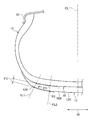
図2に示すように、本実施形態の空気入りタイヤ10を適用リム30に装着してタイヤ規格(本実施形態ではJATMA)の最大荷重(最大負荷能力)に対応する最大空気圧を充填し、水平、かつ平坦な路面31に対してタイヤ回転軸を路面と平行にした状態で最大荷重の100%の荷重を負荷させた時のラグ溝16を溝長手方向(溝幅中心線GCLにおいて)に沿った断面で見たときに、ラグ溝16は、接地端12Eの近傍においては、溝深さがタイヤ赤道面CL側から接地端12Eに向けて溝深さが徐々に浅くなるように形成されて溝底16Bが路面31に接した踏面12Aに対して傾斜しており、タイヤ赤道面CL側においては、溝底16Bが路面31に接地した踏面12Aに対して平行で溝深さが一定に形成されている。なお、図2においては、センター周方向溝14、及びショルダー側周方向溝20の図示を省略している。
図2に示すように、本実施形態の空気入りタイヤ10を適用リム30に装着してタイヤ規格(本実施形態ではJATMA)の最大荷重(最大負荷能力)に対応する最大空気圧を充填し、水平、かつ平坦な路面31に対してタイヤ回転軸を路面と平行にした状態で最大荷重の100%の荷重を負荷させた時のラグ溝16を溝長手方向(溝幅中心線GCLにおいて)に沿った断面で見たときに、ラグ溝16は、接地端12Eの近傍においては、溝深さがタイヤ赤道面CL側から接地端12Eに向けて溝深さが徐々に浅くなるように形成されて溝底16Bが路面31に接した踏面12Aに対して傾斜しており、タイヤ赤道面CL側においては、溝底16Bが路面31に接地した踏面12Aに対して平行で溝深さが一定に形成されている。なお、図2においては、センター周方向溝14、及びショルダー側周方向溝20の図示を省略している。
ラグ溝16は、接地端12Eを通り路面31に接地した踏面12Aに対して直角な方向に延びる仮想線FL1とラグ溝16の溝底(溝幅の中心において)16Bとの交点をP1、接地端12Eからタイヤ赤道面CL側へトレッド半幅1/2TWの1/3の距離だけ離れた踏面12A上の1/3点P2を通り路面31に接触した踏面12Aに対して直角な方向に延びる仮想線FL2とラグ溝16の溝底16Bとの交点をP3としたときに、交点P1から交点P3に至るラグ溝16の溝底16Bは、路面31に接した踏面12Aに対する平均の傾斜角度θ1が5°以下に設定されている。なお、ラグ溝16は、1/3点P2からタイヤ赤道面CLの端部にかけては、溝深さが一定である。
なお、ラグ溝16の溝深さは、トレッド12の接地端12E付近の剛性が低下するため、ラグ溝16の溝深さを交点P3から交点P1にかけて増大させることはない。なお、本実施形態における剛性とは、圧縮剛性のことである。
また、ラグ溝16の接地端12Eにおける溝深さは、タイヤ赤道面CL側の端部と同等若しくは浅くなるが、タイヤ赤道面CL側の最大溝深さに対して、接地端12E側における溝深さは、100~50%の範囲内であることが好ましい。タイヤ赤道面CL側の最大溝深さに対して、接地端12Eにおける溝深さが50%未満では、ラグ溝16の溝深さが浅くなり過ぎて排水性能が低下する。一方、接地端12Eにおける溝深さが100%を超えると、ラグ溝16の溝深さが深くなり過ぎて、接地端12E付近のブロック剛性が低下する虞がある。
また、ラグ溝16の接地端12Eにおける溝深さは、タイヤ赤道面CL側の端部と同等若しくは浅くなるが、タイヤ赤道面CL側の最大溝深さに対して、接地端12E側における溝深さは、100~50%の範囲内であることが好ましい。タイヤ赤道面CL側の最大溝深さに対して、接地端12Eにおける溝深さが50%未満では、ラグ溝16の溝深さが浅くなり過ぎて排水性能が低下する。一方、接地端12Eにおける溝深さが100%を超えると、ラグ溝16の溝深さが深くなり過ぎて、接地端12E付近のブロック剛性が低下する虞がある。
なお、ラグ溝16の溝長手方向に沿った断面形状について、空気入りタイヤ10に荷重を負荷させ路面に接地させた状態の図2に基づいて説明をしたが、以下に、空気入りタイヤ10を無負荷状態とした場合で説明する。
図3には、本実施形態の空気入りタイヤ10を適用リム30に装着してタイヤ規格(本実施形態ではJATMA)の最大荷重(最大負荷能力)に対応する最大空気圧を充填し、荷重を負荷させていない時のラグ溝16の溝長手方向に沿った断面が示されている。図3に示すように、ラグ溝16は、接地端12Eの近傍において、溝深さがタイヤ赤道面CL側から接地端12Eに向けて溝深さが徐々に浅くなっており、タイヤ赤道面CL側においては、溝深さが一定となっている。なお、図3においては、センター周方向溝14、及びショルダー側周方向溝20の図示を省略している。
図3には、本実施形態の空気入りタイヤ10を適用リム30に装着してタイヤ規格(本実施形態ではJATMA)の最大荷重(最大負荷能力)に対応する最大空気圧を充填し、荷重を負荷させていない時のラグ溝16の溝長手方向に沿った断面が示されている。図3に示すように、ラグ溝16は、接地端12Eの近傍において、溝深さがタイヤ赤道面CL側から接地端12Eに向けて溝深さが徐々に浅くなっており、タイヤ赤道面CL側においては、溝深さが一定となっている。なお、図3においては、センター周方向溝14、及びショルダー側周方向溝20の図示を省略している。
ラグ溝16は、接地端12Eを通り踏面12Aに対して直角な方向に延びる仮想線FL1とラグ溝16の溝底(溝幅の中心において)16Bとの交点をP1、接地端12Eからタイヤ赤道面CL側へトレッド半幅1/2TWの1/3の距離だけ離れた踏面12A上の1/3点P2を通り踏面12Aに対して直角な方向に延びる仮想線FL2とラグ溝16の溝底16Bとの交点をP3としたときに、交点P1と交点P3との間の溝底16Bと、接地端12Eと1/3点P2との間の踏面12Aとが成す平均の傾斜角度θ2が5°以下に設定されている。
(ラグ溝の長手方向に対して直角な断面形状)
図4に示すように、本実施形態のラグ溝16は、溝幅(W0)中心線GCLを境にしてタイヤ回転方向側(矢印A方向側)とタイヤ回転方向側とは反対方向側(矢印B方向側)とで非対称形状となっている。
図4に示すように、本実施形態のラグ溝16は、溝幅(W0)中心線GCLを境にしてタイヤ回転方向側(矢印A方向側)とタイヤ回転方向側とは反対方向側(矢印B方向側)とで非対称形状となっている。
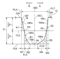
図4に示すように、ラグ溝16は、各ブロックの踏み込み側の溝側壁16Fにおいて、ラグ溝16の溝深さDの1/2の深さ位置P4を境にして踏面12A側が踏み込み側第1傾斜部16Fa(本発明の第1溝側壁)、溝底側が踏み込み側第2傾斜部16Fb(本発明の第2溝側壁)とされている。一方、溝幅中心線GCLを境にして蹴り出し側の溝側壁16Kにおいて、ラグ溝16の溝深さDの1/2の深さ位置P5を境にして踏面12A側が蹴り出し側第1傾斜部16Ka(本発明の第1溝側壁)、溝底側が蹴り出し側第2傾斜部16Kb(本発明の第2溝側壁)とされている。
このラグ溝16において、踏み込み側第1傾斜部16Faの溝幅方向に沿って計測した幅寸法はW1、踏み込み側第2傾斜部16Fbの溝幅方向に沿って計測した幅寸法はW2、蹴り出し側第1傾斜部16Kaの溝幅方向に沿って計測した幅寸法はW3、蹴り出し側第2傾斜部16Kbの溝幅方向に沿って計測した幅寸法はW4とする。
ここで、踏み込み側第2傾斜部16Fbの幅寸法W2、及び蹴り出し側第2傾斜部16Kbの幅寸法W4は、ラグ溝16の溝幅W0の20~50%の範囲内に設定することが好ましい。
なお、ラグ溝16において、最深部分を溝底16Bと呼び、ラグ溝16を長手方向に対して直交する断面で見たときに、溝底16Bは、例えば、図4に示すように溝幅方向に寸法を有する場合と、例えば、図6に示すように溝幅方向に寸法を有していない場合がある。
ここで、踏み込み側第2傾斜部16Fbの幅寸法W2、及び蹴り出し側第2傾斜部16Kbの幅寸法W4は、ラグ溝16の溝幅W0の20~50%の範囲内に設定することが好ましい。
なお、ラグ溝16において、最深部分を溝底16Bと呼び、ラグ溝16を長手方向に対して直交する断面で見たときに、溝底16Bは、例えば、図4に示すように溝幅方向に寸法を有する場合と、例えば、図6に示すように溝幅方向に寸法を有していない場合がある。
ここで、踏み込み側第1傾斜部16Faの踏面12側の端部を通り、踏面12Aに対して垂直な仮想線をFL3(本発明の第1仮想線)、踏み込み側第2傾斜部16Fbの踏面12側の端部(=溝深さDの1/2の深さ位置P4。踏み込み側第1傾斜部16Faの溝底側の端部。)を通り、踏面12Aに対して垂直な仮想線をFL4(本発明の第3仮想線)、踏み込み側第2傾斜部16Fbの踏面12側の端部(=溝深さDの1/2の深さ位置P4)を通り、仮想線FL3と直交して溝幅方向に沿って延びる仮想線をFL5(本発明の第2仮想線)、ラグ溝16の最深部(ここでは、溝幅中心線GCLと溝底16Bとの交点P6)を通り、踏面と平行で溝幅方向に沿って延びる仮想線をFL6(本発明の第4仮想線)、仮想線FL3、仮想線FL5、及び踏み込み側第1傾斜部16Faで囲まれる略三角形の領域(右上がりの斜線部分)の面積をA1、仮想線FL4、仮想線FL6、及び踏み込み側第2傾斜部16Fbで囲まれる略三角形の領域(左上がりの斜線部分)の面積をB1と定義したときに、A1<B1に設定されている。
A1<B1とすることで、ラグ溝16の溝のボリュームを確保しつつ、各ブロックの踏み込み側の溝側壁16Fの溝底側のブロック剛性を高めることができ、各ブロックの踏み込み側の溝側壁16Fの溝底側のブロック剛性を高めることで各ブロックの踏み込み側全体のブロック剛性を高めることができる。
なお、B1とA1との比率B1/A1は、ブロック剛性をより高めるには120%以上とすることが好ましく、ブロック剛性をさらに高めるには180%以上とすることがより好ましく、270%以上とすることがより一層好ましい。比率B1/A1の上限は実用的には500%であるが、無限大(∞:A1が零の場合(例えば、踏み込み側第1傾斜部16Faが踏面に対して直角な場合等))であっても良い。
なお、B1とA1との比率B1/A1は、ブロック剛性をより高めるには120%以上とすることが好ましく、ブロック剛性をさらに高めるには180%以上とすることがより好ましく、270%以上とすることがより一層好ましい。比率B1/A1の上限は実用的には500%であるが、無限大(∞:A1が零の場合(例えば、踏み込み側第1傾斜部16Faが踏面に対して直角な場合等))であっても良い。
また、蹴り出し側第1傾斜部16Kaの踏面12側の端部を通り、踏面12Aに対して垂直な仮想線をFL7、蹴り出し側第2傾斜部16Kbの踏面12側の端部(=溝深さDの1/2の深さ位置P5。蹴り出し側第1傾斜部16Kaの溝底側の端部。)を通り、踏面12Aに対して垂直な仮想線をFL8、仮想線FL7、仮想線FL5、及び蹴り出し側第1傾斜部16Kaで囲まれる略三角形の領域(右上がりの斜線部分)の面積をA2、仮想線FL8、仮想線FL6、及び蹴り出し側第2傾斜部16Kbで囲まれる略三角形の領域(左上がりの斜線部分)の面積をB2と定義したときに、A2<B2に設定されている。なお、B2とA2との比率B2/A2は、120%以上とすることが好ましく、ブロック剛性を高めるには180%以上とすることがより好ましく、270%以上とすることがより一層好ましい。比率B2/A2の上限は実用的には500%であるが、無限大(∞:A2が零の場合(例えば、蹴り出し側第1傾斜部16Kaが踏面に対して直角な場合等))であっても良い。
A2<B2とすることで、ラグ溝16の溝のボリュームを確保しつつ、センター側ブロック22、及びショルダー側ブロック26の蹴り出し側の溝側壁16Kの溝底側のブロック剛性を高めることができ、各ブロックの蹴り出し側の溝側壁16Kの溝底側のブロック剛性を高めることで各ブロックの蹴り出し側全体のブロック剛性を高めることができる。
また、本実施形態では、比率B1/A1と、比率B2/A2とを対比したときに、比率B1/A1<比率B2/A2に設定されている。これにより、センター側ブロック22、及びショルダー側ブロック26において、踏み込み側のブロック剛性よりも蹴り出し側のブロック剛性が高められている。
さらに、本実施形態のラグ溝16は、タイヤ赤道面CL側から接地端12Eに向けて、踏み込み側第2傾斜部16Fbの円弧状部分の曲率半径Ra、及び蹴り出し側第2傾斜部16Kbの円弧状部分の曲率半径Rbが増大され、その結果、踏み込み側第2傾斜部16Fbの幅寸法W2、及び蹴り出し側第2傾斜部16Kbの幅寸法W4が増大してタイヤ赤道面CL側から接地端12Eに向けて面積B1、及び面積B2が増大している。これにより、センター側ブロック22、及びショルダー側ブロック26の踏み込み側のブロック剛性、及び蹴り出し側のブロック剛性が、タイヤ赤道面CL側から接地端12Eに向けて増大している。
(作用、効果)
従来の空気入りタイヤでは、ブロック剛性を高めるために、ブロックを区画する溝の溝側壁全体を傾斜させていたが、これでは、溝のボリュームが減少し、ウエット性能が低下するため、ブロック剛性とウエット性能とを高度に両立することが困難であったが、本実施形態の空気入りタイヤ10では、ブロック剛性とウエット性能とを高度に両立することが可能となる。以下に、本実施形態の空気入りタイヤ10を車両に装着した場合の作用効果を説明する。
従来の空気入りタイヤでは、ブロック剛性を高めるために、ブロックを区画する溝の溝側壁全体を傾斜させていたが、これでは、溝のボリュームが減少し、ウエット性能が低下するため、ブロック剛性とウエット性能とを高度に両立することが困難であったが、本実施形態の空気入りタイヤ10では、ブロック剛性とウエット性能とを高度に両立することが可能となる。以下に、本実施形態の空気入りタイヤ10を車両に装着した場合の作用効果を説明する。
空気入りタイヤ10がウエット路面を走行した際には、接地面内の水(トレッド12の踏面12Aと路面との間に介在する水)は、センター周方向溝14、ラグ溝16、及びショルダー側周方向溝20に取り込まれ、センター周方向溝14、及びショルダー側周方向溝20によってタイヤ周方向外側に排水され、ラグ溝16によってタイヤ幅方向外側に排水される。なお、センター周方向溝14、及びショルダー側周方向溝20に取り込まれた水の一部は、ラグ溝16を介してタイヤ幅方向外側に排水される。本実施形態の空気入りタイヤ10は、このようにして接地面内の水を排水し、ウエット性能を得ている。また、本実施形態の空気入りタイヤ10では、タイヤ赤道面CL上にタイヤ周方向に沿って延びるセンター周方向溝14が配置されているので、接地圧の高いタイヤセンター部での排水性能を高めることができ。
本実施形態の空気入りタイヤ10では、各ブロックの踏み込み側において、仮想線FL3、仮想線FL5、及び踏み込み側第1傾斜部16Faで囲まれる略三角形の領域の面積A1と、仮想線FL4、仮想線FL6、及び踏み込み側第2傾斜部16Fbで囲まれる略三角形の領域の面積B1とを比較したときに、A1<B1に設定されているので、センター側ブロック22、及びショルダー側ブロック26の各ブロックの踏み込み側の溝底側(即ち、各ブロックの踏み込み側の基部)の剛性を高めることができ、これによって、ラグ溝16の排水性能に必要な溝のボリュームを確保しつつ、各ブロックの踏み込み側のブロック剛性を高めることができる。
さらに、本実施形態の空気入りタイヤ10では、各ブロックの蹴り出し側において、仮想線FL7、仮想線FL5、及び蹴り出し側第1傾斜部16Kaで囲まれる略三角形の領域の面積A2と、仮想線FL8、仮想線FL6、及び蹴り出し側第2傾斜部16Kbで囲まれる略三角形の領域の面積B2とを比較したときに、A2<B2に設定されているので、各ブロックの蹴り出し側の溝底側(即ち、各ブロックの蹴り出し側の基部)の剛性を高めることができ、ラグ溝16の排水性能に必要な溝のボリュームを確保しつつ、各ブロックの蹴り出し側のブロック剛性を高めることができる。
以上説明した様に、本実施形態の空気入りタイヤ10では、各ブロックの踏み込み側のブロック剛性、及び蹴り出し側のブロック剛性を高めることで、ドライ路面での操縦安定性に必要なブロック全体のブロック剛性を高めることができる。また、本実施形態の空気入りタイヤ10では、ブロック剛性を高めるために溝側壁全体を傾斜させてトレッド12のゴムの使用量を増やすことが無いので、転がり抵抗の増大も抑制できる。
このようにして、本実施形態の空気入りタイヤ10は、ウエット性能(特には、ハイドロプレーニング性能)、及びドライ性能(特には、ドライ路面での操縦安定性能)を得つつ、ウエット性能とドライ性能との高度な両立が可能となる。また、センター側ブロック22、及びショルダー側ブロック26の各ブロックの変形が抑えられることにより、各ブロックの路面に対する引き摺りが抑えられ、各ブロックの耐摩耗性を向上させることができる。
さらに、本実施形態の空気入りタイヤ10では、比率B1/A1<比率B2/A2に設定されて、センター側ブロック22、及びショルダー側ブロック26の各ブロックにおいて、踏み込み側のブロック剛性よりも蹴り出し側のブロック剛性が高められているため、蹴り出し側のブロック剛性よりも踏み込み側のブロック剛性を高めた場合に比較して、空気入りタイヤ10が矢印A方向に回転(駆動時)して各ブロックが路面に接地した際のタイヤ周方向の変形を効果的に抑えることができる。
また、本実施形態の空気入りタイヤ10では、タイヤ赤道面CL側から接地端12Eに向けて、ラグ溝16の踏み込み側第2傾斜部16Fbの円弧状部分の曲率半径Ra、及び蹴り出し側第2傾斜部16Kbの円弧状部分の曲率半径Rbが増大されてタイヤ赤道面CL側から接地端12Eに向けて面積B1、及び面積B2が増大しているため、センター側ブロック22、及びショルダー側ブロック26の踏み込み側のブロック剛性、及び蹴り出し側のブロック剛性を、タイヤ赤道面CL側から接地端12Eに向けて増大させることができる。このため、コーナリング時にトレッド12のショルダー側、即ち、接地端12E側に大きな荷重が掛かった場合に、接地端12E側にあるショルダー側ブロック26の変形を効果的に抑制することができ、ラグ溝16の接地端12E側の溝のボリュームを確保しつつ、コーナリング性能を向上させることができる。
また、踏み込み側第2傾斜部16Fbのラグ溝底側、及び蹴り出し側第2傾斜部16Kbのラグ溝底側が共に円弧状に形成されているので、ラグ溝16の溝底16Bにおいて応力集中が抑えられ、溝底16Bからのクラックの発生が抑制され、また、ラグ溝16の内部に水が流れた際に、水の流れが乱流にならず層流になり易いため、排水性能も向上する。
ここで、踏み込み側第2傾斜部16Fbの幅寸法W2、及び蹴り出し側第2傾斜部16Kbの幅寸法W4を、ラグ溝16の溝幅W0の20~50%の範囲内に設定することで、ブロック剛性と、排水性能とを高度に両立することができる。なお、ラグ溝16の溝幅W0に対する幅寸法W2、及び幅寸法W4の割合が20%未満になると、ブロック剛性を十分に高めることが困難となる。一方、ラグ溝16の溝幅W0に対する幅寸法W2、及び幅寸法W4の割合が50%を超えると、ラグ溝16のボリュームを十分に確保することが困難となる。また、幅寸法W2、及び幅寸法W4の何れか一方を大きくし過ぎると、何れか他方を大きくすることが出来なくなる。
なお、ラグ溝16は、接地端12Eに向かうにつれてタイヤ幅方向に対する傾斜角度θ0が漸減しており、さらに、ラグ溝16のタイヤ幅方向に対する傾斜角度θ0の変化が、タイヤ幅方向中央側よりも接地端12E側の方で大きくなっているため、ラグ溝16の延びている方向が、トレッド12と路面との間の水が接地面外へ流れやすい方向に近づく。このため、排水性能が向上し、ウエット性能を向上することができる。
ウエット路面走行時に接地面内で取り込んだ水をタイヤ赤道面CL側から接地端12E側に向けて流して、接地端12E側の端部からタイヤ外側へ排水するラグ溝16は、接地端12E付近において、接地端12Eに向けて徐々に溝深さが浅くなるように溝底16Bが傾斜しているが、溝底16Bの傾斜角度θ1が5°以下に設定されているため、溝内に取り込んだ水を接地端12E付近において接地端12Eに向けてスムーズに流して排水することができ、ウエット性能を向上させることができる。また、本実施形態のラグ溝16は、タイヤ赤道面CL側から接地端12E側に向けて溝幅を広くしているため、これによってもタイヤ赤道面CL側から接地端12E側への排水性能を向上させることができ、ウエット性能を更に向上させることができる。
また、本実施形態の空気入りタイヤ10では、ラグ溝16は、接地端12E付近において、接地端12Eに向けて徐々に溝深さが浅くなるように溝底16Bが傾斜しているため、接地端12Eに向けて徐々に溝深さが深くなるように溝底16Bが傾斜している場合のように、ブロック剛性を低下させる虞が無く、ドライ性能に必要な接地端12E付近のブロック剛性が確保される。このように、ラグ溝16のみぞ底16Bの傾斜角度θ1を5度以下に設定することで、ウエット性能とドライ性能とを高度に両立させることが可能となる。
なお、本実施形態の空気入りタイヤ10は、ラグ溝16のセンター周方向溝14への接続部の断面積をa(mm2)、ラグ溝16の接地端12Eにおける断面積をc(mm2)とするとき、a<c、を満たすことが好ましい。これは、ラグ溝16内を流れる水の入口側の断面積aを小さくし、ラグ溝16内を流れる水の出口側の断面積cを大きくすることにより、センター周方向溝14からラグ溝16に合流する水量が増大することによる乱流の発生を抑制して、ラグ溝16を1つの主水流路とした排水性能を高めることができ、空気入りタイヤ10の排水性能を向上させることができるからである。ここで、具体的には、ラグ溝16の溝幅は、トレッド幅方向内側端部で0~2.0mmとし、接地端12Eで9.0mm~12.0mmとすることが好ましい。
また、ショルダー側周方向溝20のタイヤ周方向一方側の端部のラグ溝16への接続部の断面積をb(mm2)とするとき、b<c、を満たすことが好ましい。これは、ショルダー側周方向溝20からラグ溝16に合流する水量が増大することによる乱流の発生を抑制して、ラグ溝16を主水流路とした排水性能をより高めることができるからである。同様の理由により、比b/cは、0.60以下とすることが好ましく、0.42以下とすることがさらに好ましい。一方で、ショルダー側周方向溝20での水の排出量を確保するためには、比b/cを0.07以上とすることが好ましい。
ここで、上記断面積aは、0~18mm2であることが好ましい。断面積aを0mm2以上とすることにより、雪上トラクション性能を向上させることができ、一方で、断面積aを18mm2以下とすることにより、上述した乱流の発生を抑制して、ラグ溝16を主水流路とした排水性能をより高めることができるからである。
また、上記断面積bは、8~46mm2であることが好ましい。断面積bを8mm2以上とすることにより、雪詰まりを抑制し、また、周方向溝3bでの水の排出量を確保することができ、一方で、断面積bを46mm2以下とすることにより、上述した乱流の発生を抑制して、ラグ溝16を主水流路とした排水性能をより高めることができるからである。
さらに、上記断面積cは、77~110mm2であることが好ましい。断面積cを77mm2以上とすることにより、主水流路となるラグ溝16で流す水の流量を確保して排水性能を向上させることができ、一方で、断面積cを110mm2以下とすることにより、接地面積を確保してドライ路面での走行性能等を確保することができるからである。
なお、本実施形態の空気入りタイヤ10では、比率B1/A1<比率B2/A2に設定されて、第1のブロック22、及びショルダー側ブロック26の各ブロックにおいて、踏み込み側のブロック剛性よりも蹴り出し側のブロック剛性が高められていたが、本発明はこれに限らず、比率B1/A1>比率B2/A2に設定して、第1のブロック22、及びショルダー側ブロック26の各ブロックにおいて、蹴り出し側のブロック剛性よりも踏み込み側のブロック剛性を高めるようにしても良い。
また、例えば、トレッド12に、周方向の寸法が長いショルダー側ブロック26と、周方向の寸法が短いショルダー側ブロック26とが混在する場合、周方向の寸法が短いショルダー側ブロック26の方が、周方向の寸法が長いショルダー側ブロック26よりも相対的にブロック剛性が小さくなる。このような場合には、例えば、周方向の寸法が短いショルダー側ブロック26を区画するラグ溝16の踏み込み側の曲率半径Ra、及び蹴り出し側の曲率半径Rbを、周方向の寸法が長いショルダー側ブロック26を区画するラグ溝16の踏み込み側の曲率半径Ra、及び蹴り出し側の曲率半径Rbよりも大きくする等の手法を用いて、周方向の寸法が短いショルダー側ブロック26に面する溝側壁の剛性を、周方向の寸法が長いショルダー側ブロック26に面する溝側壁の剛性よりも高めることが好ましい。これにより、ラグ溝16の溝のボリュームを確保しつつ、周方向の寸法が短いショルダー側ブロック26のブロック剛性を高める効果が、周方向の寸法が長いショルダー側ブロック26のブロック剛性を高める効果よりも大となり、周方向の寸法が短いショルダー側ブロック26と周方向の寸法が長いショルダー側ブロック26とのブロック剛性の差を小さくすることができる。
ラグ溝16は、タイヤ幅方向に延び、あるいは、タイヤ幅方向に対して45゜以下の角度で傾斜して延びていれば良い。ラグ溝16をタイヤ転動時の流水方向に沿って延ばすことにより排水性能を高めることができる。ラグ溝16の溝深さ(最大深さ)は、排水するための溝のオリュームを確保するため、1.0~9.2mmとすることが好ましい。ラグ溝16は、排水性能とドライ路面や氷雪路面における制動性能や操縦安定性とを高度に両立させるためには、タイヤ周方向に16~20mmのピッチ間隔で配置することが好ましい。図1に示すように、ラグ溝16は、パターンノイズを低減するために、タイヤ赤道面CLを境界にしてタイヤ幅方向一方側と他方側とで、トレッド周方向に位相差を設けて配置することが好ましい。
また、第3の周方向溝20は、排水性能と氷雪路面における操縦安定性とを高度に両立させるために、タイヤ周方向に延び、あるいは、タイヤ周方向に対して0゜以上45゜未満の角度で傾斜して延びることが好ましい。第3の周方向溝20の溝幅は、排水性能とドライ路面や氷雪路面における制動性能や操縦安定性とを高度に両立させるために、2.0~10.0mmとすることが好ましい。第3の周方向溝20の溝深さ(最大深さ)は、排水性能とドライ路面や氷雪路面における制動性能や操縦安定性とを高度に両立させるために、4.0~9.2mmとすることが好ましい。
なお、本実施形態の空気入りタイヤ10においては、トレッド12の踏面12Aのネガティブ率(トレッド踏面の面積に対する、トレッド踏面内の溝面積の割合)は、排水性能とドライ路面や氷雪路面における制動性能や操縦安定性と高度に両立させるために33~40%とすることが好ましい。また、ラグ溝16を主水流路として十分機能させるために、ラグ溝16の溝面積は、第3の周方向溝20より大きいことが好ましく、全溝面積のうちの50%以上がラグ溝16の溝面積であることが好ましい。
[第2の実施形態]
次に、本発明の第2の実施形態に係る空気入りタイヤ10を図5にしたがって説明する。なお、第1の実施形態と同一構成には同一符号を付し、その説明は省略する。
図5に示すように、本実施形態の空気入りタイヤ10のラグ溝16は、踏み込み側の溝側壁16F、及び蹴り出し側の溝側壁16Kが、複数の直線状部分で形成されている。
本実施形態の空気入りタイヤ10もA1<B1、A2<B2設定されているので、第1の実施形態と同様に、ラグ溝16の排水性能に必要な溝のボリュームを確保しつつ、各ブロックのブロック剛性を高めることができる。
次に、本発明の第2の実施形態に係る空気入りタイヤ10を図5にしたがって説明する。なお、第1の実施形態と同一構成には同一符号を付し、その説明は省略する。
図5に示すように、本実施形態の空気入りタイヤ10のラグ溝16は、踏み込み側の溝側壁16F、及び蹴り出し側の溝側壁16Kが、複数の直線状部分で形成されている。
本実施形態の空気入りタイヤ10もA1<B1、A2<B2設定されているので、第1の実施形態と同様に、ラグ溝16の排水性能に必要な溝のボリュームを確保しつつ、各ブロックのブロック剛性を高めることができる。
[第3の実施形態]
次に、本発明の第3の実施形態に係る空気入りタイヤ10を図6にしたがって説明する。なお、第1の実施形態と同一構成には同一符号を付し、その説明は省略する。
図6に示すように、本実施形態の空気入りタイヤ10のラグ溝16は、第1の実施形態に比較して踏み込み側第2傾斜部16Fbの円弧状部分の曲率半径Ra、及び蹴り出し側第2傾斜部16Kbの円弧状部分の曲率半径Rbが大きく設定されており、踏み込み側第2傾斜部16Fbの円弧状部分と蹴り出し側第2傾斜部16Kbの円弧状部分とが滑らかに接続されている。
本実施形態の空気入りタイヤ10もA1<B1、A2<B2設定されているので、第1の実施形態と同様に、ラグ溝16の排水性能に必要な溝のボリュームを確保しつつ、各ブロックのブロック剛性を高めることができる。
また、本実施形態では、曲率半径Ra、及び曲率半径Rbが第1の実施形態よりも大きく設定されているため、第1の実施形態よりもブロック剛性を高めることが出来る。
次に、本発明の第3の実施形態に係る空気入りタイヤ10を図6にしたがって説明する。なお、第1の実施形態と同一構成には同一符号を付し、その説明は省略する。
図6に示すように、本実施形態の空気入りタイヤ10のラグ溝16は、第1の実施形態に比較して踏み込み側第2傾斜部16Fbの円弧状部分の曲率半径Ra、及び蹴り出し側第2傾斜部16Kbの円弧状部分の曲率半径Rbが大きく設定されており、踏み込み側第2傾斜部16Fbの円弧状部分と蹴り出し側第2傾斜部16Kbの円弧状部分とが滑らかに接続されている。
本実施形態の空気入りタイヤ10もA1<B1、A2<B2設定されているので、第1の実施形態と同様に、ラグ溝16の排水性能に必要な溝のボリュームを確保しつつ、各ブロックのブロック剛性を高めることができる。
また、本実施形態では、曲率半径Ra、及び曲率半径Rbが第1の実施形態よりも大きく設定されているため、第1の実施形態よりもブロック剛性を高めることが出来る。
[第4の実施形態]
次に、本発明の第4の実施形態に係る空気入りタイヤ10を図7~図10にしたがって説明する。なお、第1の実施形態と同一構成は同一符号を付し、その説明は省略する。
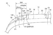
図7に示すように、本実施形態の空気入りタイヤ10は、ラグ溝16のタイヤ赤道面CL側の端部における溝深さD0に対して、ラグ溝16の溝底16Bの交点P1と交点P3(1/3点P2の直下)との間における平均の溝深さD1が90%以上に設定されている。
次に、本発明の第4の実施形態に係る空気入りタイヤ10を図7~図10にしたがって説明する。なお、第1の実施形態と同一構成は同一符号を付し、その説明は省略する。
図7に示すように、本実施形態の空気入りタイヤ10は、ラグ溝16のタイヤ赤道面CL側の端部における溝深さD0に対して、ラグ溝16の溝底16Bの交点P1と交点P3(1/3点P2の直下)との間における平均の溝深さD1が90%以上に設定されている。
このように、ラグ溝16の溝深さがD1≦90%D0に設定されている場合は、図7、及び図8に示すように、1/3点P2からタイヤ幅方向外側に配置されるサイプ28、すなわち本実施形態では、ショルダー側ブロック26のサイプ28の内部に、ショルダー側ブロック26のブロック剛性を高めるために、溝底16Bから隆起して溝深さを浅くする底上げ部32を設けることが好ましい。
図7、及び図8に示すように、サイプ28に設ける底上げ部32の長さL’は、ブロック剛性を高める効果を得るために、1.5mm以上に設定することが好ましい。
図7に示すように、底上げ部32の高さ寸法(サイプ28の溝底から計測)hは、サイプ28の溝深さ寸法よりも小さく、底上げ部32の頂部の位置は、トレッド12の踏面12Aよりも低い(即ち、タイヤ径方向内側にある。)。本実施形態では、サイプ28に底上げ部32が2個設けられているが、少なくとも1個設けられていれば良く、3個以上設けられていても良く、ブロック剛性を高めたい部位に設けることができる。
図7に示すように、底上げ部32の高さ寸法(サイプ28の溝底から計測)hは、サイプ28の溝深さ寸法よりも小さく、底上げ部32の頂部の位置は、トレッド12の踏面12Aよりも低い(即ち、タイヤ径方向内側にある。)。本実施形態では、サイプ28に底上げ部32が2個設けられているが、少なくとも1個設けられていれば良く、3個以上設けられていても良く、ブロック剛性を高めたい部位に設けることができる。
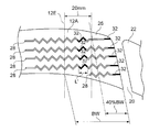
図7、及び図8に示すように、ショルダー側ブロック26において、タイヤ幅方向内側端からタイヤ幅方向外側に向けて延び、かつ接地端12Eを横断する複数のサイプ28が形成され、該サイプ28がラグ溝16の溝深さが60%以上の溝深さを有する場合、これら複数のサイプ28の内の少なくとも半数以上のサイプ28においては、ショルダー側ブロック26の接地端12E側のブロック剛性を高めるために、接地端12Eからタイヤ幅方向内側へ20mmの範囲内に、高さhが2mm以上4mm以下の底上げ部32を設けることが好ましい。ここで、底上げ部32の高さhが2mm未満では、ブロック剛性を高める効果が不足し、底上げ部32の高さhが4mmを超えると、ブロック剛性が部分的に高くなり過ぎる。
さらに、ショルダー側ブロック26のタイヤ幅方向内側のブロック剛性を高めるために、ショルダー側ブロック26のタイヤ幅方向内側端から接地端12E側に向けてショルダー側ブロック26の接地幅(タイヤ幅方向の)BWの40%の範囲内に底上げ部32を設けることが好ましい。なお、ショルダー側ブロック26のタイヤ幅方向内側端から接地端12E側に向けてショルダー側ブロック26の接地幅(タイヤ幅方向の)BWの40%の範囲に設ける底上げ部32の高さは、2mm以上5mm以下とすることが好ましい。
図8に示すように、ショルダー側ブロック26のタイヤ幅方向内側端から接地端12E側に向けてショルダー側ブロック26の接地幅(タイヤ幅方向の)BWの40%の範囲において、各サイプ28に底上げ部32が設けられ、各底上げ部32が一方向沿って直線状に並んでブロック剛性が部分的に高くなり過ぎるような場合には、図示は省略するが、高さの高い底上げ部32(例えば、高さ5mmの底上げ部32)を備えたサイプ28と、高さの高い底上げ部32に対して相対的に高さの低い底上げ部32(例えば、高さ2mmの底上げ部32)を備えたサイプ28とを、タイヤ周方向に交互に配置することが好ましい。これにより、ショルダー側ブロック26のタイヤ幅方向内側部分のブロック剛性を適度に高め、ショルダー側ブロック26の耐摩耗性を向上することができる。
また、ショルダー側ブロック26に底上げ部32を備えた複数のサイプ28が形成され、かつ各底上げ部32が一方向に沿って直線状に並んでブロック剛性が部分的に高くなり過ぎるような場合には、図9に示すように、底上げ部32を設けたサイプ28と、底上げ部32を設けていないサイプ28とをタイヤ周方向に交互に配置することで、ブロック剛性の部分的な高まりを抑え、ブロック剛性を適度に高めることも出来る。
さらに、底上げ部32を設けたサイプ28をタイヤ周方向に複数並べる場合、タイヤ周方向に隣接するサイプ28の底上げ部32がタイヤ周方向に互いに隣り合わないように、図10に示すように、一方のサイプ28の底上げ部32と他方のサイプ28の底上げ部32とをタイヤ幅方向にずらすことで、ブロック剛性の部分的な高まりを抑え、ブロック剛性を適度に高めることも出来る。
[第5の実施形態]
次に、本発明の第5の実施形態に係る空気入りタイヤ10を図11にしたがって説明する。なお、前述した実施形態と同一構成には同一符号を付し、その説明は省略する。
図11に示すように、本実施形態の空気入りタイヤ10のラグ溝16には、接地端12Eからタイヤ幅方向内側へ向けて、踏面12Aと溝底16Bとが平行とされた溝深さが一定の平行部分16Bbが設けられており、平行部分16Bbのタイヤ幅方向内側に、溝深さが深くなる方向に傾斜した傾斜部分16Baが設けられている。なお、傾斜部分16Baのタイヤ幅方向内側端からタイヤ赤道面CL側へ向けては、踏面12Aと溝底16Bとが平行とされ溝深さが一定に設定されている。なお、本実施形態においても、交点P1から交点P3に至るラグ溝16の溝底16Bは、路面31に接した踏面12Aに対する平均の傾斜角度θ1が5°以下に設定されている。
次に、本発明の第5の実施形態に係る空気入りタイヤ10を図11にしたがって説明する。なお、前述した実施形態と同一構成には同一符号を付し、その説明は省略する。
図11に示すように、本実施形態の空気入りタイヤ10のラグ溝16には、接地端12Eからタイヤ幅方向内側へ向けて、踏面12Aと溝底16Bとが平行とされた溝深さが一定の平行部分16Bbが設けられており、平行部分16Bbのタイヤ幅方向内側に、溝深さが深くなる方向に傾斜した傾斜部分16Baが設けられている。なお、傾斜部分16Baのタイヤ幅方向内側端からタイヤ赤道面CL側へ向けては、踏面12Aと溝底16Bとが平行とされ溝深さが一定に設定されている。なお、本実施形態においても、交点P1から交点P3に至るラグ溝16の溝底16Bは、路面31に接した踏面12Aに対する平均の傾斜角度θ1が5°以下に設定されている。
本実施形態の空気入りタイヤ10のラグ溝16の溝底16Bは、交点P1から交点P3までの間が、一定角度で傾斜しておらず、接地端12E側に踏面12Aに対して平行な平行部分16Bbが設けられているが、交点P1から交点P3に至るラグ溝16の溝底16Bの平均の傾斜角度が5°以下に設定されており、接地端12E付近では、溝底16Bと踏面12A(路面31)とが平行で、溝深さが一定となっているため、ラグ溝16の内部に取り込まれた水は、接地端12E付近において乱流を生ずることなくスムーズに流れ、接地端12Eから接地面外側へ排水される。
[その他の実施形態]
以上、本発明の一実施形態について説明したが、本発明は、上記に限定されるものでなく、上記以外にも、その主旨を逸脱しない範囲内において種々変形して実施可能であることは勿論である。
ラグ溝16においては、少なくとも、A1<B1、及びA2<B2の少なくとも一方が設定されていれば良く、ラグ溝16の断面形状、即ち、踏み込み側の溝側壁16F、及び蹴り出し側の溝側壁16K、及び溝底16Bの断面形状は、図4,5,6に示したものに限らず、円弧以外の曲線で形成されていても良く、種々の変更が可能である。
また、比率B1/A1と、比率B2/A2とを対比したときに、比率B1/A1>比率B2/A2に設定されても良く、比率B1/A1=比率B2/A2に設定されても良い。
以上、本発明の一実施形態について説明したが、本発明は、上記に限定されるものでなく、上記以外にも、その主旨を逸脱しない範囲内において種々変形して実施可能であることは勿論である。
ラグ溝16においては、少なくとも、A1<B1、及びA2<B2の少なくとも一方が設定されていれば良く、ラグ溝16の断面形状、即ち、踏み込み側の溝側壁16F、及び蹴り出し側の溝側壁16K、及び溝底16Bの断面形状は、図4,5,6に示したものに限らず、円弧以外の曲線で形成されていても良く、種々の変更が可能である。
また、比率B1/A1と、比率B2/A2とを対比したときに、比率B1/A1>比率B2/A2に設定されても良く、比率B1/A1=比率B2/A2に設定されても良い。
[試験例1]
本発明の効果を確かめるため、従来例、及び本発明の適用された実施例のタイヤ1~4を試作した。各タイヤの諸元は、表1に示した通りである。各タイヤは、図1で示されるトレッドパターンを有しており、表1に示すようにラグ溝の溝側壁の面積A及び面積Bの関係が異なっている。
上記各タイヤについて、ウエット路面でのハイドロプレーニング性能、ドライ路面でのラップタイム、及び耐摩耗性を評価する以下の試験を行った。
本発明の効果を確かめるため、従来例、及び本発明の適用された実施例のタイヤ1~4を試作した。各タイヤの諸元は、表1に示した通りである。各タイヤは、図1で示されるトレッドパターンを有しており、表1に示すようにラグ溝の溝側壁の面積A及び面積Bの関係が異なっている。
上記各タイヤについて、ウエット路面でのハイドロプレーニング性能、ドライ路面でのラップタイム、及び耐摩耗性を評価する以下の試験を行った。
<ハイドロプレーニング性能(直線)>
タイヤサイズ195/65R15の上記各供試タイヤを適用リムに組み込んで、内圧を200kPaとして、水深7mmの湿潤路面を加速し、ハイドロプレーニング現象の発生速度を比較することにより、排水性能を評価した。
評価は、従来例にかかるタイヤの評価結果を100としたときの相対値で指数評価し、数値が大きい方がウエット性能に優れていることを示す。
タイヤサイズ195/65R15の上記各供試タイヤを適用リムに組み込んで、内圧を200kPaとして、水深7mmの湿潤路面を加速し、ハイドロプレーニング現象の発生速度を比較することにより、排水性能を評価した。
評価は、従来例にかかるタイヤの評価結果を100としたときの相対値で指数評価し、数値が大きい方がウエット性能に優れていることを示す。
<ハイドロプレーニング性能(コーナリング)>
タイヤサイズ195/65R15の上記各タイヤを適用リムに組み込んで、内圧を200kPaとして、水深5mm、半径80mのウエット路面通過時のハイドロプレーニング発生限界横Gを計測した。評価は従来例のタイヤのハイドロプレーニング発生限界横Gを100とする指数で表しており、数値が大きいほどコーナリング時のハイドロプレーニング性能が良いことを表している。
タイヤサイズ195/65R15の上記各タイヤを適用リムに組み込んで、内圧を200kPaとして、水深5mm、半径80mのウエット路面通過時のハイドロプレーニング発生限界横Gを計測した。評価は従来例のタイヤのハイドロプレーニング発生限界横Gを100とする指数で表しており、数値が大きいほどコーナリング時のハイドロプレーニング性能が良いことを表している。
<ラップタイム>
タイヤサイズ195/65R15の上記各タイヤを適用リムに組み込んで、内圧を200kPaとして、路面が乾燥したテストコースを走行してラップタイムを計測した。
評価は、従来例にかかるタイヤのラップタイムを100とした指数表示とし、数値が小さいほどラップタイムが短く、ドライ性能に優れていることを示す。
タイヤサイズ195/65R15の上記各タイヤを適用リムに組み込んで、内圧を200kPaとして、路面が乾燥したテストコースを走行してラップタイムを計測した。
評価は、従来例にかかるタイヤのラップタイムを100とした指数表示とし、数値が小さいほどラップタイムが短く、ドライ性能に優れていることを示す。
<偏摩耗性>
タイヤサイズ195/65R15の上記各タイヤを適用リムに組み込んで、内圧を200kPaとして、テストコース内でセンター部が1.2mm摩耗するまで走行させた。
摩耗量比はショルダー端部の摩耗量をセンター部の摩耗量で除したもので、数値1に近いほど均一に摩耗しており、偏摩耗性に優れている事を示す。

タイヤサイズ195/65R15の上記各タイヤを適用リムに組み込んで、内圧を200kPaとして、テストコース内でセンター部が1.2mm摩耗するまで走行させた。
摩耗量比はショルダー端部の摩耗量をセンター部の摩耗量で除したもので、数値1に近いほど均一に摩耗しており、偏摩耗性に優れている事を示す。
表1に示すように、本発明の適用された実施例1~4のタイヤは、いずれも従来例にかかるタイヤと比較して、ハイドロプレーニング性能、及びラップタイムに優れていることがわかる。

表2に示すように、本発明の適用された実施例1~4のタイヤは、いずれも従来例に係るタイヤと比較して、装着部内側端部の摩耗量とセンター部の摩耗量との比が小さく、偏摩耗性に優れていることがわかる。
表2に示すように、本発明の適用された実施例1~4のタイヤは、いずれも従来例に係るタイヤと比較して、装着部内側端部の摩耗量とセンター部の摩耗量との比が小さく、偏摩耗性に優れていることがわかる。
2015年6月15日に出願された日本国特許出願2015-120367号の開示は、その全体が参照により本明細書に取り込まれる。
本明細書に記載されたすべての文献、特許出願、及び技術規格は、個々の文献、特許出願、及び技術規格が参照により取り込まれることが具体的かつ個々に記された場合と同程度に、本明細書中に参照により取り込まれる。
本明細書に記載されたすべての文献、特許出願、及び技術規格は、個々の文献、特許出願、及び技術規格が参照により取り込まれることが具体的かつ個々に記された場合と同程度に、本明細書中に参照により取り込まれる。
Claims (7)
- 路面に接地するトレッドと、
前記トレッドに設けられ、陸部を区画する複数の溝と、
を備え、
前記溝の前記トレッドの踏面から溝深さの1/2の溝深さまでの溝側壁を第1溝側壁、溝深さの1/2の溝深さから溝底の最深部までの溝側壁を第2溝側壁とし、
前記溝の長手方向に直交する断面で見たときの、前記第1溝側壁の踏面側の端部を通り前記踏面に垂直な第1仮想線と、前記第1溝側壁の溝底側の端部を通り、かつ前記第1仮想線と直交する第2仮想線と、前記第1溝側壁とで囲まれる領域の面積をA、前記溝の長手方向に直交する断面で見たときの、前記第1溝側壁の溝底側の端部を通り前記踏面に垂直な第3仮想線と、前記溝底の最深部を通り、前記踏面と平行な第4仮想線と、前記第2溝側壁とで囲まれる領域の面積をB、としたときに、A<Bに設定されている、空気入りタイヤ。 - 面積Bと面積Aとの比率B/Aが120%以上に設定されている、請求項1に記載の空気入りタイヤ。
- 前記溝の互いに対向する一方側の溝側壁と他方側の溝側壁とを比較したときに、何れか一方の溝側壁における比率B/Aが、何れか他方の溝側壁における比率B/Aよりも大きく設定されている、請求項1または請求項2に記載の空気入りタイヤ。
- 複数の前記溝で区画される第1の陸部、及び前記第1の陸部よりも剛性の高い第2の陸部を備え、
前記第1の陸部の側壁である前記溝側壁における比率B/Aが、前記第2の陸部の側壁である前記溝側壁における比率B/Aよりも大きく設定されている、請求項3に記載の空気入りタイヤ。 - 前記陸部の蹴り出し側の前記溝側壁における比率B/Aが、前記陸部の踏み込み側の前記溝側壁における比率B/Aよりも大きく設定されている、請求項3に記載の空気入りタイヤ。
- 複数の前記溝は、タイヤ幅方向に沿って延びるラグ溝を含み、
前記ラグ溝は、タイヤ幅方向中央側からタイヤ幅方向外側に向けて前記面積Bが漸増している、請求項1~請求項5の何れか1項に記載の空気入りタイヤ。 - 前記溝の溝幅方向に沿って計測した第2溝側壁の幅寸法が、前記溝の溝幅に対して20~50%の範囲内に設定されている、請求項1~請求項6の何れか1項に記載の空気入りタイヤ。
Priority Applications (3)
| Application Number | Priority Date | Filing Date | Title |
|---|---|---|---|
| US15/577,769 US10960711B2 (en) | 2015-06-15 | 2016-04-19 | Pneumatic tire |
| CN201680034596.4A CN107735270B (zh) | 2015-06-15 | 2016-04-19 | 充气轮胎 |
| EP16811311.6A EP3308981B1 (en) | 2015-06-15 | 2016-04-19 | Pneumatic tire |
Applications Claiming Priority (2)
| Application Number | Priority Date | Filing Date | Title |
|---|---|---|---|
| JP2015120367A JP6482395B2 (ja) | 2015-06-15 | 2015-06-15 | 空気入りタイヤ |
| JP2015-120367 | 2015-06-15 |
Publications (1)
| Publication Number | Publication Date |
|---|---|
| WO2016203836A1 true WO2016203836A1 (ja) | 2016-12-22 |
Family
ID=57545135
Family Applications (1)
| Application Number | Title | Priority Date | Filing Date |
|---|---|---|---|
| PCT/JP2016/062436 Ceased WO2016203836A1 (ja) | 2015-06-15 | 2016-04-19 | 空気入りタイヤ |
Country Status (5)
| Country | Link |
|---|---|
| US (1) | US10960711B2 (ja) |
| EP (1) | EP3308981B1 (ja) |
| JP (1) | JP6482395B2 (ja) |
| CN (1) | CN107735270B (ja) |
| WO (1) | WO2016203836A1 (ja) |
Cited By (2)
| Publication number | Priority date | Publication date | Assignee | Title |
|---|---|---|---|---|
| CN112498015A (zh) * | 2017-01-18 | 2021-03-16 | 诺基安伦卡特股份有限公司 | 用于充气轮胎或胎面带的胎面块结构 |
| JP2022014301A (ja) * | 2020-07-06 | 2022-01-19 | 住友ゴム工業株式会社 | 空気入りタイヤ |
Families Citing this family (6)
| Publication number | Priority date | Publication date | Assignee | Title |
|---|---|---|---|---|
| JP6907690B2 (ja) * | 2017-05-16 | 2021-07-21 | 住友ゴム工業株式会社 | タイヤ |
| CN109501525A (zh) * | 2018-09-30 | 2019-03-22 | 安徽佳通乘用子午线轮胎有限公司 | 一种高里程低滚阻全钢子午线轮胎 |
| JP2022178529A (ja) * | 2021-05-20 | 2022-12-02 | Toyo Tire株式会社 | タイヤ |
| JP7808469B2 (ja) * | 2021-12-28 | 2026-01-29 | Toyo Tire株式会社 | 空気入りタイヤ |
| DE102022211347A1 (de) * | 2022-10-26 | 2024-05-02 | Continental Reifen Deutschland Gmbh | Fahrzeugluftreifen |
| CN115674956B (zh) * | 2022-11-16 | 2024-10-29 | 正新橡胶(中国)有限公司 | 一种雪地轮胎花纹 |
Citations (9)
| Publication number | Priority date | Publication date | Assignee | Title |
|---|---|---|---|---|
| JPH10278515A (ja) * | 1997-04-10 | 1998-10-20 | Bridgestone Corp | 空気入りタイヤ |
| JP2009190468A (ja) * | 2008-02-12 | 2009-08-27 | Bridgestone Corp | 重荷重用空気入りラジアルタイヤ |
| JP2011245913A (ja) * | 2010-05-24 | 2011-12-08 | Bridgestone Corp | 空気入りタイヤ |
| JP2011245888A (ja) * | 2010-05-21 | 2011-12-08 | Bridgestone Corp | 空気入りタイヤ |
| JP2012020654A (ja) * | 2010-07-14 | 2012-02-02 | Yokohama Rubber Co Ltd:The | 空気入りタイヤ |
| JP2012148678A (ja) * | 2011-01-19 | 2012-08-09 | Bridgestone Corp | 空気入りタイヤ |
| JP2012188111A (ja) * | 2011-02-25 | 2012-10-04 | Bridgestone Corp | 空気入りタイヤ |
| JP2014189161A (ja) * | 2013-03-27 | 2014-10-06 | Toyo Tire & Rubber Co Ltd | 空気入りタイヤ |
| WO2015002154A1 (ja) * | 2013-07-02 | 2015-01-08 | 株式会社ブリヂストン | 空気入りタイヤ |
Family Cites Families (25)
| Publication number | Priority date | Publication date | Assignee | Title |
|---|---|---|---|---|
| DE888654C (de) * | 1951-04-17 | 1953-09-03 | Continental Gummi Werke Ag | Schlepperreifen, insbesondere fuer landwirtschaftliche Zwecke |
| GB1195241A (en) | 1967-03-28 | 1970-06-17 | Dunlop Co Ltd | Improvements in or relating to Pneumatic Tyres |
| JPS5023644B1 (ja) | 1971-04-01 | 1975-08-09 | ||
| JPS5638475A (en) | 1979-09-05 | 1981-04-13 | Fujitsu Ltd | Fabrication of photomask |
| US4865099A (en) * | 1984-02-27 | 1989-09-12 | The Goodyear Tire & Rubber Company | Tire treads with variable depth grooves |
| JPS60145902U (ja) * | 1984-03-09 | 1985-09-27 | 株式会社ブリヂストン | 段付きラグタイヤ |
| JPS60197409A (ja) | 1984-03-21 | 1985-10-05 | Toyo Tire & Rubber Co Ltd | 自動車用空気タイヤ |
| JPH0659765B2 (ja) | 1984-09-03 | 1994-08-10 | 住友ゴム工業株式会社 | 重車両用タイヤ |
| JPS63159107A (ja) * | 1986-12-22 | 1988-07-02 | Yokohama Rubber Co Ltd:The | 空気入りタイヤ |
| JP3262871B2 (ja) | 1992-12-16 | 2002-03-04 | 横浜ゴム株式会社 | 空気入りラジアルタイヤ |
| JPH11139113A (ja) | 1997-11-12 | 1999-05-25 | Bridgestone Corp | 重荷重用空気入りタイヤ |
| CN100475567C (zh) | 2003-03-25 | 2009-04-08 | 米其林技术公司 | 在施工机械上安装轮胎的方法以及相关的轮胎 |
| FR2878190B1 (fr) | 2004-11-24 | 2007-01-12 | Michelin Soc Tech | Profil transversal de rainure de bande de roulement |
| US7337816B2 (en) * | 2005-02-25 | 2008-03-04 | The Goodyear Tire & Rubber Company | Tire tread with circumferential and lateral grooves having asymmetrical cross-section |
| JP2007001434A (ja) | 2005-06-23 | 2007-01-11 | Yokohama Rubber Co Ltd:The | 空気入りタイヤ |
| JP5023644B2 (ja) | 2006-10-06 | 2012-09-12 | 横浜ゴム株式会社 | 空気入りタイヤ |
| JP4367965B1 (ja) | 2009-03-16 | 2009-11-18 | 横浜ゴム株式会社 | 空気入りタイヤ |
| JP4951043B2 (ja) | 2009-08-25 | 2012-06-13 | 住友ゴム工業株式会社 | 空気入りタイヤ |
| EP2679409B1 (en) | 2011-02-25 | 2018-05-02 | Kabushiki Kaisha Bridgestone | Pneumatic tire |
| US10252576B2 (en) | 2011-12-27 | 2019-04-09 | Bridgestone Corporation | Pneumatic tire |
| JP6107041B2 (ja) | 2012-10-11 | 2017-04-05 | 横浜ゴム株式会社 | 空気入りタイヤ |
| JP6306862B2 (ja) | 2013-11-18 | 2018-04-04 | 住友ゴム工業株式会社 | 空気入りタイヤ |
| JP6594051B2 (ja) | 2015-06-08 | 2019-10-23 | 株式会社ブリヂストン | タイヤ |
| JP6482396B2 (ja) * | 2015-06-15 | 2019-03-13 | 株式会社ブリヂストン | 空気入りタイヤ |
| JP6537184B2 (ja) | 2015-11-18 | 2019-07-03 | Toyo Tire株式会社 | 空気入りタイヤ |
-
2015
- 2015-06-15 JP JP2015120367A patent/JP6482395B2/ja active Active
-
2016
- 2016-04-19 US US15/577,769 patent/US10960711B2/en active Active
- 2016-04-19 EP EP16811311.6A patent/EP3308981B1/en active Active
- 2016-04-19 WO PCT/JP2016/062436 patent/WO2016203836A1/ja not_active Ceased
- 2016-04-19 CN CN201680034596.4A patent/CN107735270B/zh not_active Expired - Fee Related
Patent Citations (9)
| Publication number | Priority date | Publication date | Assignee | Title |
|---|---|---|---|---|
| JPH10278515A (ja) * | 1997-04-10 | 1998-10-20 | Bridgestone Corp | 空気入りタイヤ |
| JP2009190468A (ja) * | 2008-02-12 | 2009-08-27 | Bridgestone Corp | 重荷重用空気入りラジアルタイヤ |
| JP2011245888A (ja) * | 2010-05-21 | 2011-12-08 | Bridgestone Corp | 空気入りタイヤ |
| JP2011245913A (ja) * | 2010-05-24 | 2011-12-08 | Bridgestone Corp | 空気入りタイヤ |
| JP2012020654A (ja) * | 2010-07-14 | 2012-02-02 | Yokohama Rubber Co Ltd:The | 空気入りタイヤ |
| JP2012148678A (ja) * | 2011-01-19 | 2012-08-09 | Bridgestone Corp | 空気入りタイヤ |
| JP2012188111A (ja) * | 2011-02-25 | 2012-10-04 | Bridgestone Corp | 空気入りタイヤ |
| JP2014189161A (ja) * | 2013-03-27 | 2014-10-06 | Toyo Tire & Rubber Co Ltd | 空気入りタイヤ |
| WO2015002154A1 (ja) * | 2013-07-02 | 2015-01-08 | 株式会社ブリヂストン | 空気入りタイヤ |
Cited By (4)
| Publication number | Priority date | Publication date | Assignee | Title |
|---|---|---|---|---|
| CN112498015A (zh) * | 2017-01-18 | 2021-03-16 | 诺基安伦卡特股份有限公司 | 用于充气轮胎或胎面带的胎面块结构 |
| CN112498015B (zh) * | 2017-01-18 | 2022-04-12 | 诺基安伦卡特股份有限公司 | 用于充气轮胎或胎面带的胎面块结构 |
| JP2022014301A (ja) * | 2020-07-06 | 2022-01-19 | 住友ゴム工業株式会社 | 空気入りタイヤ |
| JP7476694B2 (ja) | 2020-07-06 | 2024-05-01 | 住友ゴム工業株式会社 | 空気入りタイヤ |
Also Published As
| Publication number | Publication date |
|---|---|
| EP3308981A1 (en) | 2018-04-18 |
| EP3308981B1 (en) | 2019-08-14 |
| US10960711B2 (en) | 2021-03-30 |
| CN107735270A (zh) | 2018-02-23 |
| JP6482395B2 (ja) | 2019-03-13 |
| JP2017001616A (ja) | 2017-01-05 |
| EP3308981A4 (en) | 2018-05-09 |
| US20180126792A1 (en) | 2018-05-10 |
| CN107735270B (zh) | 2020-03-03 |
Similar Documents
| Publication | Publication Date | Title |
|---|---|---|
| JP6482395B2 (ja) | 空気入りタイヤ | |
| JP4862090B2 (ja) | 空気入りタイヤ | |
| CN104955660B (zh) | 充气轮胎 | |
| JP5685237B2 (ja) | 空気入りタイヤ | |
| CN103287218B (zh) | 充气轮胎 | |
| JP5102711B2 (ja) | 空気入りタイヤ | |
| JP5971280B2 (ja) | 空気入りタイヤ | |
| CN100522665C (zh) | 充气轮胎 | |
| CN101835634B (zh) | 充气轮胎 | |
| CN104349915B (zh) | 充气轮胎 | |
| US11167597B2 (en) | Tire | |
| KR20120098423A (ko) | 공기 타이어 | |
| JP2017170939A (ja) | 空気入りタイヤ | |
| JP6450261B2 (ja) | 空気入りタイヤ | |
| JP7035550B2 (ja) | 空気入りタイヤ | |
| JP3809173B2 (ja) | 空気入りタイヤ | |
| JP6482396B2 (ja) | 空気入りタイヤ | |
| JP7225865B2 (ja) | タイヤ | |
| JP2005186850A (ja) | 空気入りタイヤ | |
| CN104822544B (zh) | 充气轮胎 | |
| JP3917406B2 (ja) | 空気入りタイヤ | |
| JP5623824B2 (ja) | 空気入りタイヤ | |
| JP2024041802A (ja) | 空気入りタイヤ | |
| JPWO2022145182A5 (ja) | ||
| JP2003054223A (ja) | 空気入りタイヤ |
Legal Events
| Date | Code | Title | Description |
|---|---|---|---|
| 121 | Ep: the epo has been informed by wipo that ep was designated in this application |
Ref document number: 16811311 Country of ref document: EP Kind code of ref document: A1 |
|
| WWE | Wipo information: entry into national phase |
Ref document number: 15577769 Country of ref document: US |
|
| NENP | Non-entry into the national phase |
Ref country code: DE |
|
| WWE | Wipo information: entry into national phase |
Ref document number: 2016811311 Country of ref document: EP |