WO2016208169A1 - Dispositif et procédé de spécification - Google Patents
Dispositif et procédé de spécification Download PDFInfo
- Publication number
- WO2016208169A1 WO2016208169A1 PCT/JP2016/002929 JP2016002929W WO2016208169A1 WO 2016208169 A1 WO2016208169 A1 WO 2016208169A1 JP 2016002929 W JP2016002929 W JP 2016002929W WO 2016208169 A1 WO2016208169 A1 WO 2016208169A1
- Authority
- WO
- WIPO (PCT)
- Prior art keywords
- light
- time
- optical fiber
- distance
- reflected light
- Prior art date
- Legal status (The legal status is an assumption and is not a legal conclusion. Google has not performed a legal analysis and makes no representation as to the accuracy of the status listed.)
- Ceased
Links
Images


Classifications
-
- G—PHYSICS
- G01—MEASURING; TESTING
- G01M—TESTING STATIC OR DYNAMIC BALANCE OF MACHINES OR STRUCTURES; TESTING OF STRUCTURES OR APPARATUS, NOT OTHERWISE PROVIDED FOR
- G01M11/00—Testing of optical apparatus; Testing structures by optical methods not otherwise provided for
- G01M11/30—Testing of optical devices, constituted by fibre optics or optical waveguides
- G01M11/31—Testing of optical devices, constituted by fibre optics or optical waveguides with a light emitter and a light receiver being disposed at the same side of a fibre or waveguide end-face, e.g. reflectometers
- G01M11/3109—Reflectometers detecting the back-scattered light in the time-domain, e.g. OTDR
-
- G—PHYSICS
- G01—MEASURING; TESTING
- G01M—TESTING STATIC OR DYNAMIC BALANCE OF MACHINES OR STRUCTURES; TESTING OF STRUCTURES OR APPARATUS, NOT OTHERWISE PROVIDED FOR
- G01M11/00—Testing of optical apparatus; Testing structures by optical methods not otherwise provided for
-
- G—PHYSICS
- G01—MEASURING; TESTING
- G01M—TESTING STATIC OR DYNAMIC BALANCE OF MACHINES OR STRUCTURES; TESTING OF STRUCTURES OR APPARATUS, NOT OTHERWISE PROVIDED FOR
- G01M11/00—Testing of optical apparatus; Testing structures by optical methods not otherwise provided for
- G01M11/30—Testing of optical devices, constituted by fibre optics or optical waveguides
- G01M11/33—Testing of optical devices, constituted by fibre optics or optical waveguides with a light emitter being disposed at one fibre or waveguide end-face, and a light receiver at the other end-face
- G01M11/335—Testing of optical devices, constituted by fibre optics or optical waveguides with a light emitter being disposed at one fibre or waveguide end-face, and a light receiver at the other end-face using two or more input wavelengths
-
- H—ELECTRICITY
- H04—ELECTRIC COMMUNICATION TECHNIQUE
- H04B—TRANSMISSION
- H04B10/00—Transmission systems employing electromagnetic waves other than radio-waves, e.g. infrared, visible or ultraviolet light, or employing corpuscular radiation, e.g. quantum communication
- H04B10/07—Arrangements for monitoring or testing transmission systems; Arrangements for fault measurement of transmission systems
- H04B10/071—Arrangements for monitoring or testing transmission systems; Arrangements for fault measurement of transmission systems using a reflected signal, e.g. using optical time domain reflectometers [OTDR]
Definitions
- the present invention relates to a device and a specifying method, and more particularly to a device and a specifying method for specifying a fault zone of an optical fiber.
- FIG. 1 is a diagram for explaining the configuration and operation of the optical pulse tester disclosed in Patent Document 1. In FIG.
- the optical pulse tester of Patent Document 1 is connected to an optical fiber line as shown in the upper diagram of FIG. A plurality of light reflection elements P1, P2,... Pn that reflect only a specific wavelength signal by a certain amount are inserted into the optical fiber line. As shown in the lower diagram of FIG. 1, the optical pulse tester of Patent Document 1 sends a specific wavelength signal (an optical signal having a specific wavelength ⁇ 1) to an optical fiber line, and reflected light from each light reflecting element arrives. At each predetermined time, the level of reflected light is measured. The reflected light from each light reflecting element is reflected light having the same wavelength ⁇ 1.
- a specific wavelength signal an optical signal having a specific wavelength ⁇ 1
- the optical pulse tester of Patent Document 1 specifies that a failure has occurred up to the position where a light reflecting element corresponding to the time is inserted for a time when the optical fiber has a failure and no reflected light of a predetermined level is detected. . Further, the optical pulse tester disclosed in Patent Document 1 assumes that there is no obstacle up to the position where the light reflecting element corresponding to the time is inserted for the time when the reflected light of a predetermined level is detected.
- the optical pulse tester disclosed in Patent Document 1 can identify a faulty section of an optical fiber.
- the optical pulse tester of Patent Document 1 has a problem that the manufacturing cost cannot be sufficiently reduced in identifying the fault section of the optical fiber.
- the optical pulse tester of Patent Document 1 uses the reflected light received from the light reflecting elements P1, P2, and P3 as the reflected light from the light reflecting element P4 during the time when the reflected light from the light reflecting element P4 arrives. It is determined that there is no obstacle up to the light reflecting element P4.
- the optical pulse tester of Patent Document 1 cannot identify a faulty section of an optical fiber line when reflected light of the same wavelength returns. In order to specify the fault section, the optical pulse tester of Patent Document 1 needs to strictly control the transmission time of the optical signal so that the reflected lights do not overlap. As a result, the optical pulse tester of Patent Document 1 must be equipped with a circuit (for example, a pulse signal generator) for strictly controlling the transmission time of the optical signal, which can sufficiently reduce the manufacturing cost. There was a problem that it was not possible.
- An object of the present invention is to provide an apparatus and a specifying method for solving the above problems.
- an apparatus of the present invention is an apparatus connected to an optical fiber in which a light reflecting element that reflects a certain amount of light is inserted, sends light to the optical fiber, and transmits the light.
- Stopping sending means measuring means for measuring the intensity of the reflected light reflected from the light reflecting element, and the reflected light measured by the measuring means after the sending means stops sending the light
- a time measuring means for measuring the time until the strength of the signal becomes a predetermined value or less; a distance measuring means for calculating a distance corresponding to the time measured by the time measuring means; and a signal indicating the distance is output.
- Output means, and the predetermined value is greater than or equal to the intensity of the reflected light when the light is not transmitted, and the light reflection inserted farthest when the light is transmitted Of the reflected light received from the element. It is a value smaller than of.
- light is transmitted to an optical fiber in which a light reflecting element that reflects a certain amount of light is inserted, and the intensity of reflected light reflected from the light reflecting element is increased.
- Measure measure the time from stopping the light transmission and stopping the light transmission until the intensity of the reflected light to be measured becomes a predetermined value or less, and correspond to the measured time A distance to be calculated, and a signal indicating the distance is output, and the predetermined value is equal to or greater than the intensity of the reflected light when the light is not transmitted and is the farthest when the light is transmitted. It is a value smaller than the intensity of the reflected light received from the light reflecting element inserted into the.
- the device can sufficiently reduce the manufacturing cost when specifying the fault section of the optical fiber.
- FIG. It is a figure for demonstrating the structure and operation
- FIG. It is a figure for demonstrating the apparatus connected to the optical transmission / reception apparatus in the 1st Embodiment of this invention. It is a figure for demonstrating the light reflection element connected to the optical transmission / reception apparatus in the 1st Embodiment of this invention. It is a figure which shows the structural example of the optical transmission / reception apparatus in the 1st Embodiment of this invention. It is a flowchart which shows operation
- the optical transmission / reception apparatus of this embodiment sends light to an optical fiber in which a plurality of light reflecting elements that reflect a certain amount of light are inserted for an appropriate time. Light is transmitted when there is a failure in the optical fiber. By transmitting light, the optical transmission / reception apparatus of this embodiment receives reflected light of the same wavelength from each light reflecting element in a superimposed manner. Thereafter, the optical transmission / reception device stops the transmission of light and measures the time until all the reflected light is not received. The measured time corresponds to the time for light to reciprocate between the farthest light reflecting elements that are connected even after a failure.
- the optical transmission / reception apparatus calculates the distance to the farthest light reflecting element to be connected after the failure.
- the calculated distance is information indicating that there is a failure in a further section, that is, information for specifying the failure section.
- the optical transmission / reception apparatus according to the present embodiment does not need to strictly control the light transmission time so that the reflected light does not overlap in order to identify the faulty section, and does not need a circuit for that purpose, so the manufacturing cost can be sufficiently reduced. .
- FIG. 2 is a diagram for explaining devices connected to the optical transceiver according to the first embodiment of the present invention.
- FIG. 3 is a diagram for explaining the light reflecting element connected to the optical transceiver in the first embodiment of the present invention.
- an optical fiber 2 is connected to the optical transmitter / receiver 1 of the present embodiment.
- the light reflecting elements 3_1, 3_2,..., 3_n described above reflect a certain amount of light when the light is incident from the optical transmitting / receiving device 1 and transmit the remaining light as transmitted light.
- the optical fiber grating may be provided on the optical fiber 2 by a known phase mask method.
- the reflectance of the optical fiber grating may be about 1% to 10%.
- the optical transmission / reception apparatus 1 is connected to an optical fiber 2 provided with an optical fiber grating at every predetermined distance.
- one end of the optical fiber 2 may be connected to another optical transceiver 4 as shown in FIG.
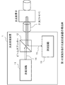
- FIG. 4 is a diagram illustrating a configuration example of the optical transmission / reception device 1 according to the first embodiment of the present invention.
- the optical transmission / reception apparatus 1 includes a transmission circuit 11, a beam splitter 12, and a measurement circuit 13, as shown in FIG.
- the transmission circuit 11 is connected to the optical fiber 2 via the optical fiber 14 and the beam splitter 12. Further, the measurement circuit 13 is connected to the optical fiber 2 via the optical fiber 15 and the beam splitter 12. Although not shown, the transmission circuit 11 is connected to the measurement circuit 13 via a conducting wire.
- the signal indicating the start of transmission described above may be input from a monitoring device (not shown) connected to the transmission circuit 11.
- the operator of the monitoring device inputs a signal indicating the start of transmission from the monitoring device to the transmission circuit 11 when a failure occurs in the optical fiber 2.
- the transmission circuit 11 transmits light and stops transmitting light after a predetermined time has elapsed. When the transmission circuit 11 stops the transmission of light, the transmission circuit 11 outputs a signal indicating the transmission stop to the measurement circuit 13.
- the above-mentioned predetermined time is set in the transmission circuit 11 by the user of the optical transmission / reception apparatus 1 of the present embodiment.
- the user of the optical transmission / reception apparatus 1 of the present embodiment may set an arbitrary time (for example, 3 seconds) in the transmission circuit 11.
- the measuring circuit 13 has a timekeeping function. When a signal indicating stop of transmission is input, the measurement circuit 13 starts measuring time by a time measuring function. This is to measure the time after stopping the transmission.
- the measuring circuit 13 receives reflected light via the beam splitter 12.
- the measurement circuit 13 measures the intensity of the reflected light received at a predetermined timing.
- the above-mentioned predetermined timing is a timing at regular intervals, and is set in the measurement circuit 13 by the user of the optical transmission / reception apparatus 1 of the present embodiment.
- the predetermined timing is preferably a timing with a shorter interval, and the user of the optical transmission / reception apparatus 1 of the present embodiment may set a timing every several tens of microseconds in the measurement circuit 13 as the predetermined timing. .
- the measurement circuit 13 may include a general light receiving element and an AD (Analog to Digital) converter.
- the light receiving element is provided at a position for receiving the reflected light.
- the AD converter reads the intensity of the electric signal (analog signal) output from the light receiving element at every predetermined timing (for example, several tens of microseconds), and writes the read value in the memory in the measurement circuit 13. Go.
- a value written in a memory (hereinafter referred to as “storage memory”) in the measurement circuit 13 is a value indicating the intensity of reflected light.
- the measurement circuit 13 can measure the intensity of the reflected light at every predetermined timing using the light receiving element and the AD converter.
- the reflected light measurement function operates in parallel with other functions (for example, a timekeeping function).
- (3-5) Time Stop Function When the measurement circuit 13 stops receiving reflected light, it stops measuring time. Specifically, the measurement circuit 13 stops the time measuring function when the intensity of the reflected light most recently measured by the reflected light measuring function (the value most recently written to the storage memory) is equal to or less than a predetermined value, Stop measuring.
- the above-mentioned predetermined value is the intensity of the reflected light when no reflected light is received, and is set in the measurement circuit 13 in advance by the user of the optical transceiver 1 of the present embodiment.
- the user of the optical transmission / reception apparatus 1 sets the intensity of the reflected light measured by the reflected light measurement function as a predetermined value when the optical fiber 2 is not obstructed and the transmission circuit 11 is not transmitting light. May be set.
- the time measured by the timekeeping function before the timekeeping function is stopped is the time from when the light transmission is stopped until the reflected light is not received.
- the time is the time from when the transmission of light is stopped until the farthest light reflecting element connected is transmitted as light and reflected and returned. This corresponds to the time for light to travel back and forth.
- the measurement circuit 13 calculates the distance to the farthest connected light reflecting element based on the measured time.
- the measurement circuit 13 is configured such that half of the measured time (that is, the time for light to reciprocate between the farthest connected light reflecting elements) and the speed at which the light travels in the optical fiber. Calculate the product.
- the speed at which light travels in the optical fiber can be obtained by dividing the speed of light by the refractive index of the optical fiber.
- the speed at which the light travels in the optical fiber is calculated in advance by the user of the optical transmission / reception apparatus 1 of the present embodiment and set in the measurement circuit 13.
- the refractive index is 1.458 and the speed of light is 29997.458 [km / s], so that the speed of light traveling in the optical fiber is 20557. 927 [km / s].
- the user of the optical transmission / reception device 1 of the present embodiment sets 20557.927 [km / s] in the measurement circuit 13 when connecting an optical fiber using general quartz glass to the optical transmission / reception device 1.
- the measurement circuit 13 outputs the calculated distance to the farthest connected light reflecting element as a signal.
- the transmission circuit 11 can be realized using a laser diode, an optical fiber, and an electronic circuit.
- the measurement circuit 13 can be realized by using an electronic circuit, a memory such as a RAM (Random Access Memory), a light receiving element, an AD converter, an optical fiber, and an optical adapter.
- a RAM Random Access Memory
- FIG. 5 is a flowchart showing the operation of the optical transceiver 1 in the first embodiment of the present invention. The detailed operation of the optical transmission / reception apparatus 1 according to the present embodiment will be described below with reference to FIG.
- the transmission circuit 11 of the optical transceiver 1 transmits light to the optical fiber 2 as shown in FIG. 5 (S1).
- Light is a constant level optical signal.
- reflected light of the same wavelength is returned from the light reflecting elements 3_1, 3_2,.
- the measuring circuit 13 of the optical transceiver 1 receives the reflected light from the light reflecting elements 3_1, 3_2,. At this time, the measurement circuit 13 repeatedly measures the intensity of the reflected light received at regular intervals, as described above in “(3-4) Reflected light measurement function”.
- the transmission circuit 11 transmits light in the above-described S1, stops the transmission of light after a predetermined time (for example, 3 seconds), and further outputs a signal indicating the transmission stop to the measurement circuit 13 (S2). .
- the measurement circuit 13 determines whether or not the intensity of the reflected light measured most recently is not more than a predetermined value (S4). This is to determine whether or not the reflected light is no longer received.
- the measurement circuit 13 If the intensity of the reflected light measured most recently is not less than or equal to the predetermined value (No in S4), the measurement circuit 13 considers that the reflected light continues to be received, returns to S4, and again measures immediately. It is determined whether or not the intensity of the reflected light is less than a predetermined value.
- the measurement circuit 13 After that, when the intensity of the measured reflected light becomes equal to or less than a predetermined value (Yes in S4), the measurement circuit 13 considers that the reflected light is not received and stops measuring time (S5). .
- Measured time is the time from when light transmission is stopped until no reflected light is received. As described in the above (3-6), the time corresponds to the time for light to reciprocate with the farthest light reflecting element that is normally connected even after the occurrence of a failure.
- the measurement circuit 13 calculates the distance to the farthest light reflecting element that is normally connected based on the measured time ( S6).
- the measurement circuit 13 uses half of the measured time (the time in which light travels back and forth between the farthest light reflecting elements that are normally connected even after a failure occurs) and the light travels in the optical fiber. Calculate the product of speed.
- the speed at which the light travels in the optical fiber is calculated by the user of the optical transmission / reception apparatus 1 of the present embodiment and set in the measurement circuit 13 in advance as described in the above “(3-7) Distance calculation function”. .
- the measurement circuit 13 outputs the distance calculated in S6 (the distance to the farthest light reflecting element that is normally connected even after the failure occurs) as a signal (S7).
- the optical transceiver 1 performs normal connection even after a failure occurs by performing the above-described processing of S1 to S7 when there is a failure in the optical fiber.
- the distance to the farthest light reflecting element is output.
- the distance output by the optical transmission / reception device 1 of the present embodiment is information indicating that there is no failure up to that distance, but there is a failure in a longer section, that is, information for identifying the failure section.
- the optical transmission / reception apparatus 1 according to the present embodiment can specify a failure section.
- the measurement circuit 13 outputs the distance to the farthest light reflecting element that is normally connected.
- a monitoring device (not shown) may be used. In this case, the monitoring device displays the input distance on a screen provided for itself. The user of the optical transmission / reception device 1 can know the failure section through the monitoring device.
- the predetermined value set in measurement circuit 13 is the intensity of reflected light when no reflected light is received (hereinafter referred to as “unreceived light level”). ”), but is not limited to this.
- the above-mentioned predetermined value is smaller than the intensity of reflected light received from the light reflecting element 3_n inserted farthest (hereinafter referred to as “the reflected light level from the farthest”), and is an arbitrary value equal to or higher than the unreceived level. There may be.
- the user of the optical transmission / reception device 1 first transmits light to the optical fiber 2 and then stops transmission.
- the user of the optical transmission / reception apparatus 1 knows the distance to the light reflecting element 3_n, the user can also know in advance the time zone for receiving the reflected light from the light reflecting element 3_n.
- the user of the optical transmission / reception apparatus 1 reflects the intensity of the reflected light measured by the reflected light measurement function from the farthest in the time zone in which the reflected light from the light reflecting element 3_n is received after stopping the transmission of light. Calculate as light level.
- the above-mentioned non-light-receiving level and the reflected light level from the farthest are obtained in a state where the optical fiber 2 is connected and the optical fiber has no obstacle.
- the measurement circuit 13 may repeatedly perform S4 to S6 as a variation of the operation until a predetermined time has elapsed after S3. In that case, the measurement circuit 13 does not stop the time measurement in S5, and stores the measured time at that time. In S6, the measurement circuit 13 calculates the product of half of the time stored in S5 and the speed at which light travels in the optical fiber. When the predetermined time has elapsed, the measurement circuit 13 stops measuring time and performs S7.
- the predetermined time may be a time in seconds. The predetermined time is set in the measurement circuit 13 by the user of the optical transmission / reception apparatus 1 of the present embodiment.
- the optical transmitter / receiver 1 can sufficiently reduce the manufacturing cost when specifying the fault section of the optical fiber.
- the optical transmission / reception apparatus 1 measures the time from when the transmission of light is stopped until no reflected light is received when specifying the failure section, and after the occurrence of the failure, based on the measured time. Also calculate the distance to the farthest light reflecting element that is normally connected. Since the above-described time and distance can be measured or calculated even if the reflected light from the light reflecting element overlaps, the optical transmission / reception apparatus 1 of the present embodiment strictly sets the light transmission time so that the reflected light does not overlap. There is no need to control.
- the optical transmission / reception apparatus 1 according to the present embodiment does not need to strictly control the light transmission time, and therefore does not need a circuit (for example, a pulse signal generator) for that purpose, and can sufficiently reduce the manufacturing cost. Can do.
- FIG. 6 is a diagram for additionally explaining the effect of the optical transceiver 1.
- the optical transmission / reception apparatus 1 according to the present embodiment specifies a faulty section of an optical fiber sufficiently correctly even if light transmitted from the transmission circuit 11 leaks to the measurement circuit 13 for some reason. You can also This is because the optical transmission / reception apparatus 1 according to the present embodiment starts measurement after the transmission of light is stopped and there is no leakage.
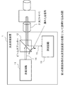
- FIG. 7 is a diagram illustrating a configuration example of the device 100 according to the second embodiment of the present invention. The configuration and operation of the apparatus 100 according to the second embodiment will be described below.
- the apparatus 100 includes a sending unit 101, a measuring unit 102, a time measuring unit 103, a distance measuring unit 104, and an output unit 105.
- the sending unit 101 and the measuring unit 102 are connected to the optical fiber 120 via a general optical splitter.
- the measuring unit 102 is connected to the time measuring unit 103 via a conducting wire.
- the distance measuring unit 104 is connected to the time measuring unit 103 and the output unit 105 through a conducting wire.
- the sending unit 101 sends light to the optical fiber 120 and stops sending light.
- the sending unit 101 may send light when an electrical signal indicating that a failure has occurred in the optical fiber 120 is input. Further, the sending unit 101 may stop sending light after a predetermined time has elapsed after sending light.
- the predetermined time is an arbitrary time set in the sending unit 101 by the user of the apparatus 100 of the present embodiment.
- the measuring unit 102 measures the intensity of the reflected light reflected from the light reflecting elements 110, 111, and 112.
- the time measuring unit 103 measures the time from when the sending unit 101 stops sending light until the intensity of the reflected light measured by the measuring unit 102 becomes a predetermined value or less. This is to measure the time from when the transmission of light is stopped until the reflected light is not received.
- the above-mentioned predetermined value is the intensity of the reflected light measured by the measurement unit 102 when the transmitting unit 101 is not transmitting light, that is, when no reflected light is received (first embodiment). Similarly to the above, it may be referred to as an “unreceived light level” hereinafter.
- the predetermined value is set in the time measurement unit 103 by the user of the apparatus 100 of the present embodiment.
- any value can be set as the predetermined value. This is because the reflected light level is the smallest of the intensity of the reflected light from each light reflecting element, and it can always be detected that the reflected light is not received.
- the distance measuring unit 104 calculates a distance corresponding to the time measured by the time measuring unit 103.
- the output unit 105 outputs a signal indicating the distance calculated by the distance measuring unit 104.
- the user of the device 100 according to the present embodiment who has recognized the failure of the optical fiber 120 presses a button provided on the device 100, and the device 100 that has pressed the button indicates that the optical fiber 120 has failed. Assume that a signal is output to the sending unit 101. An electrical signal indicating that a failure has occurred is input to the sending unit 101.
- the sending unit 101 sends light to the optical fiber 120 when an electrical signal indicating that a failure has occurred in the optical fiber 120 is input.
- reflected light of the same wavelength is returned to the sending unit 101 from each of the light reflecting elements 110, 111, and 112 on the optical fiber 120.
- the measurement unit 102 repeatedly measures the intensity of the reflected light received.
- the sending unit 101 stops sending light after sending light.
- the time measuring unit 103 determines whether the intensity of the reflected light measured by the measuring unit 102 after the sending unit 101 stops sending light is a predetermined value (not yet measured). Measure the time until the light reception level is below. That is, the time measuring unit 103 measures the time from when the transmission of light is stopped until no reflected light is received.
- Measured time is the time for light to reciprocate with the farthest light reflecting element that is normally connected even after a failure occurs.
- the distance measuring unit 104 calculates a distance corresponding to the time measured by the time measuring unit 103.
- the distance measurement unit 104 performs light transmission in the optical fiber for half of the measured time (the time for which light travels back and forth between the farthest light reflecting elements that are normally connected even after a failure occurs). Calculates the product of the speed at which The speed at which light travels in the optical fiber can be obtained by dividing the speed of light by the refractive index of the optical fiber. In the case of an optical fiber using a general silica glass, it is 20557.927 [km / s]. . The speed at which the light travels through the optical fiber is set in advance in the distance measuring unit 104 by the user of the apparatus 100.
- the output unit 105 outputs a signal indicating the distance calculated by the distance measuring unit 104 (that is, the distance to the farthest light reflecting element that is normally connected even after the occurrence of a failure).
- the distance indicated by the output signal is information indicating that there is a failure in a further section, that is, information for specifying the failure section.
- the optical transmission / reception apparatus 1 can identify a failure section.
- the light reflecting elements inserted into the optical fiber 120 are the three light reflecting elements 110, 111, and 112 .
- the number is not limited to three. Three or more light reflecting elements may be inserted into the optical fiber 120, or two or less may be inserted.
- the apparatus can sufficiently reduce the manufacturing cost when specifying the fault section of the optical fiber.
- the apparatus of this embodiment measures the time from when the transmission of light is stopped until the reflected light is not received, and based on the measured time, it is normal after the fault occurs.
- the distance to the farthest connected light reflecting element is calculated. Since the above-mentioned time and distance can be measured or calculated even if the reflected light from the light reflecting element overlaps, the apparatus of this embodiment needs to strictly control the light transmission time so that the reflected light does not overlap. There is no. Since the apparatus according to the present embodiment does not need to strictly control the light transmission time, it is not necessary to provide a circuit (for example, a pulse signal generator) for that purpose, and the manufacturing cost can be sufficiently reduced.
- a circuit for example, a pulse signal generator
- the predetermined value is the intensity of the reflected light when the light is not transmitted.
- the distance measuring means calculates, as the distance, a value corresponding to a product of half the time and a predetermined speed at which light travels in an optical fiber;
- the apparatus according to any one of appendices 1 to 3 characterized in that: (Appendix 5) Connected to a monitoring device having display means for displaying information indicated by the input signal;
- the output means outputs a signal indicating the distance to the monitoring device;
- the predetermined value is the intensity of the reflected light when the light is not transmitted.
- the identifying method according to appendix 6, wherein: (Appendix 8) When sending, the light is sent for a predetermined time in seconds.
- the specifying method according to any one of appendices 6 to 7, characterized in that: (Appendix 9) When calculating the distance, a value corresponding to the product of half the time and a predetermined speed at which light travels through the optical fiber is calculated as the distance.
- the light reflecting element is an optical fiber grating.
Landscapes
- Physics & Mathematics (AREA)
- Chemical & Material Sciences (AREA)
- Analytical Chemistry (AREA)
- General Physics & Mathematics (AREA)
- Optics & Photonics (AREA)
- Electromagnetism (AREA)
- Engineering & Computer Science (AREA)
- Computer Networks & Wireless Communication (AREA)
- Signal Processing (AREA)
- Optical Communication System (AREA)
- Testing Of Optical Devices Or Fibers (AREA)
Abstract
La présente invention aborde le problème lié à l'impossibilité de réduire suffisamment le coût de fabrication pour spécifier une section défectueuse d'une fibre optique. Le dispositif selon la présente invention consiste en un dispositif connecté à une fibre optique (120) dans laquelle sont insérés des éléments de réflexion de la lumière (110, 111, 112) qui reflètent une quantité fixe de lumière, ledit dispositif étant pourvu d'un moyen de transmission (101) permettant de transmettre la lumière à la fibre optique et d'interrompre la transmission, d'un moyen de mesure (102) permettant de mesurer l'intensité de la lumière de réflexion réfléchie par les éléments de réflexion de la lumière, d'un moyen de mesure de temps (103) permettant de mesurer le temps écoulé depuis l'interruption de la transmission de la lumière par le moyen de transmission jusqu'à la réduction de l'intensité de la lumière de réflexion mesurée par le moyen de mesure à une valeur inférieure ou égale à une valeur prescrite, d'un moyen de mesure de distance (104) permettant de calculer une distance correspondant au temps mesuré par les moyens de mesure de temps, et d'un moyen de sortie (105) permettant d'émettre un signal indiquant la distance.
Priority Applications (3)
| Application Number | Priority Date | Filing Date | Title |
|---|---|---|---|
| JP2017524628A JP6376293B2 (ja) | 2015-06-25 | 2016-06-17 | 装置、特定方法 |
| US15/736,356 US10215663B2 (en) | 2015-06-25 | 2016-06-17 | Device and specification method |
| EP16813941.8A EP3315939B1 (fr) | 2015-06-25 | 2016-06-17 | Appareil et méthode pour spécifier une section défectueuse d'une fibre optique |
Applications Claiming Priority (2)
| Application Number | Priority Date | Filing Date | Title |
|---|---|---|---|
| JP2015-128091 | 2015-06-25 | ||
| JP2015128091 | 2015-06-25 |
Publications (1)
| Publication Number | Publication Date |
|---|---|
| WO2016208169A1 true WO2016208169A1 (fr) | 2016-12-29 |
Family
ID=57584845
Family Applications (1)
| Application Number | Title | Priority Date | Filing Date |
|---|---|---|---|
| PCT/JP2016/002929 Ceased WO2016208169A1 (fr) | 2015-06-25 | 2016-06-17 | Dispositif et procédé de spécification |
Country Status (4)
| Country | Link |
|---|---|
| US (1) | US10215663B2 (fr) |
| EP (1) | EP3315939B1 (fr) |
| JP (1) | JP6376293B2 (fr) |
| WO (1) | WO2016208169A1 (fr) |
Families Citing this family (1)
| Publication number | Priority date | Publication date | Assignee | Title |
|---|---|---|---|---|
| RU2767013C1 (ru) * | 2021-05-24 | 2022-03-16 | Федеральное государственное бюджетное образовательное учреждение высшего образования "Поволжский государственный университет телекоммуникаций и информатики" | Способ определения места повреждения оптического кабеля |
Citations (4)
| Publication number | Priority date | Publication date | Assignee | Title |
|---|---|---|---|---|
| JPS5510855B2 (fr) * | 1977-03-28 | 1980-03-19 | ||
| JPH09200132A (ja) * | 1996-01-12 | 1997-07-31 | Kokusai Denshin Denwa Co Ltd <Kdd> | 光通信線路の監視方法 |
| JPH1051401A (ja) * | 1996-08-05 | 1998-02-20 | Kokusai Denshin Denwa Co Ltd <Kdd> | 光ファイバ線路の障害位置検出装置 |
| CN101964682A (zh) * | 2010-10-22 | 2011-02-02 | 华为技术有限公司 | 分布式光纤故障定位方法和系统 |
Family Cites Families (2)
| Publication number | Priority date | Publication date | Assignee | Title |
|---|---|---|---|---|
| JPS5510855A (en) | 1978-07-10 | 1980-01-25 | Hitachi Ltd | Method of manufacturing composite rotor |
| WO2007108330A1 (fr) | 2006-03-02 | 2007-09-27 | National University Corporation Tokyo University Of Agriculture And Technology | Système de mesure de distance |
-
2016
- 2016-06-17 EP EP16813941.8A patent/EP3315939B1/fr active Active
- 2016-06-17 WO PCT/JP2016/002929 patent/WO2016208169A1/fr not_active Ceased
- 2016-06-17 JP JP2017524628A patent/JP6376293B2/ja active Active
- 2016-06-17 US US15/736,356 patent/US10215663B2/en active Active
Patent Citations (4)
| Publication number | Priority date | Publication date | Assignee | Title |
|---|---|---|---|---|
| JPS5510855B2 (fr) * | 1977-03-28 | 1980-03-19 | ||
| JPH09200132A (ja) * | 1996-01-12 | 1997-07-31 | Kokusai Denshin Denwa Co Ltd <Kdd> | 光通信線路の監視方法 |
| JPH1051401A (ja) * | 1996-08-05 | 1998-02-20 | Kokusai Denshin Denwa Co Ltd <Kdd> | 光ファイバ線路の障害位置検出装置 |
| CN101964682A (zh) * | 2010-10-22 | 2011-02-02 | 华为技术有限公司 | 分布式光纤故障定位方法和系统 |
Also Published As
| Publication number | Publication date |
|---|---|
| EP3315939A1 (fr) | 2018-05-02 |
| JPWO2016208169A1 (ja) | 2018-04-12 |
| US20180188135A1 (en) | 2018-07-05 |
| US10215663B2 (en) | 2019-02-26 |
| EP3315939A4 (fr) | 2019-02-20 |
| EP3315939B1 (fr) | 2019-12-11 |
| JP6376293B2 (ja) | 2018-08-22 |
Similar Documents
| Publication | Publication Date | Title |
|---|---|---|
| JP3908703B2 (ja) | Otdrを用いた光ネットワーク試験のためのシステム | |
| US9897515B2 (en) | Optical fiber fault locator | |
| CN102104421B (zh) | 光纤网络中分支光纤故障检测方法、装置以及光纤网络 | |
| US20070103670A1 (en) | Fault detection in optical fibers | |
| CN102752051A (zh) | 具有光时域反射功能的光网络单元光组件 | |
| WO2020168833A1 (fr) | Procédé et dispositif de surveillance de fibre optique | |
| JP5291908B2 (ja) | 光線路試験システムおよび光線路試験方法 | |
| JP6376293B2 (ja) | 装置、特定方法 | |
| JP4902213B2 (ja) | 光線路監視装置及び方法 | |
| JP4562535B2 (ja) | 光スプリッタ及び光スプリッタ監視システム | |
| JP5811259B2 (ja) | 光線路監視システム | |
| JP4568986B2 (ja) | 分岐光線路の試験方法 | |
| CN103323923A (zh) | 一种具有双重诊断故障的olt用光组件 | |
| CN109831248A (zh) | 集成fc光纤链路和网络检查的综合光纤检查装置及方法 | |
| JP3762186B2 (ja) | 光伝送路及び光線路監視装置付き光伝送路 | |
| CN108692746A (zh) | 传感监测终端、传感监测系统和传感监测方法 | |
| JPH06232817A (ja) | 光ファイバ伝送装置およびその試験方法 | |
| JP2011069721A (ja) | スプリッタモジュール、及び、それを用いた残置光コネクタの検出方法、出力ポート数の検出方法及び光伝送損失測定システム | |
| CN202455358U (zh) | 带光时域反射功能的光网络单元光电器件 | |
| JP4160939B2 (ja) | 光線路の障害探索方法 | |
| CN202818297U (zh) | 具有光时域反射功能的光网络单元光电器件 | |
| KR101563631B1 (ko) | 회선정보 송수신장치 및 회선정보 판독 시스템 | |
| JP2016109559A (ja) | 試験光遮断フィルタおよびそれを適用したインサービス試験方法 | |
| JPH02176535A (ja) | 光線路監視装置 | |
| KR101733468B1 (ko) | 회선정보 송수신장치 및 회선정보 판독 시스템 |
Legal Events
| Date | Code | Title | Description |
|---|---|---|---|
| 121 | Ep: the epo has been informed by wipo that ep was designated in this application |
Ref document number: 16813941 Country of ref document: EP Kind code of ref document: A1 |
|
| ENP | Entry into the national phase |
Ref document number: 2017524628 Country of ref document: JP Kind code of ref document: A |
|
| NENP | Non-entry into the national phase |
Ref country code: DE |
|
| WWE | Wipo information: entry into national phase |
Ref document number: 2016813941 Country of ref document: EP |