WO2017002326A1 - Procédé d'embrèvement utilisant une fraise en bout, et fraise en bout - Google Patents
Procédé d'embrèvement utilisant une fraise en bout, et fraise en bout Download PDFInfo
- Publication number
- WO2017002326A1 WO2017002326A1 PCT/JP2016/002982 JP2016002982W WO2017002326A1 WO 2017002326 A1 WO2017002326 A1 WO 2017002326A1 JP 2016002982 W JP2016002982 W JP 2016002982W WO 2017002326 A1 WO2017002326 A1 WO 2017002326A1
- Authority
- WO
- WIPO (PCT)
- Prior art keywords
- end mill
- workpiece
- main body
- dimples
- dimple
- Prior art date
- Legal status (The legal status is an assumption and is not a legal conclusion. Google has not performed a legal analysis and makes no representation as to the accuracy of the status listed.)
- Ceased
Links
Images



























Classifications
-
- B—PERFORMING OPERATIONS; TRANSPORTING
- B23—MACHINE TOOLS; METAL-WORKING NOT OTHERWISE PROVIDED FOR
- B23C—MILLING
- B23C3/00—Milling particular work; Special milling operations; Machines therefor
- B23C3/28—Grooving workpieces
-
- B—PERFORMING OPERATIONS; TRANSPORTING
- B23—MACHINE TOOLS; METAL-WORKING NOT OTHERWISE PROVIDED FOR
- B23C—MILLING
- B23C5/00—Milling-cutters
- B23C5/02—Milling-cutters characterised by the shape of the cutter
- B23C5/10—Shank-type cutters, i.e. with an integral shaft
-
- B—PERFORMING OPERATIONS; TRANSPORTING
- B23—MACHINE TOOLS; METAL-WORKING NOT OTHERWISE PROVIDED FOR
- B23C—MILLING
- B23C3/00—Milling particular work; Special milling operations; Machines therefor
-
- B—PERFORMING OPERATIONS; TRANSPORTING
- B23—MACHINE TOOLS; METAL-WORKING NOT OTHERWISE PROVIDED FOR
- B23C—MILLING
- B23C5/00—Milling-cutters
- B23C5/16—Milling-cutters characterised by physical features other than shape
- B23C5/18—Milling-cutters characterised by physical features other than shape with permanently-fixed cutter-bits or teeth
-
- B—PERFORMING OPERATIONS; TRANSPORTING
- B23—MACHINE TOOLS; METAL-WORKING NOT OTHERWISE PROVIDED FOR
- B23C—MILLING
- B23C2210/00—Details of milling cutters
- B23C2210/08—Side or top views of the cutting edge
- B23C2210/084—Curved cutting edges
-
- B—PERFORMING OPERATIONS; TRANSPORTING
- B23—MACHINE TOOLS; METAL-WORKING NOT OTHERWISE PROVIDED FOR
- B23C—MILLING
- B23C2210/00—Details of milling cutters
- B23C2210/08—Side or top views of the cutting edge
- B23C2210/086—Discontinuous or interrupted cutting edges
-
- B—PERFORMING OPERATIONS; TRANSPORTING
- B23—MACHINE TOOLS; METAL-WORKING NOT OTHERWISE PROVIDED FOR
- B23C—MILLING
- B23C2210/00—Details of milling cutters
- B23C2210/20—Number of cutting edges
- B23C2210/201—Number of cutting edges one
-
- B—PERFORMING OPERATIONS; TRANSPORTING
- B23—MACHINE TOOLS; METAL-WORKING NOT OTHERWISE PROVIDED FOR
- B23C—MILLING
- B23C2210/00—Details of milling cutters
- B23C2210/24—Overall form of the milling cutter
- B23C2210/242—Form tools, i.e. cutting edges profiles to generate a particular form
-
- B—PERFORMING OPERATIONS; TRANSPORTING
- B23—MACHINE TOOLS; METAL-WORKING NOT OTHERWISE PROVIDED FOR
- B23C—MILLING
- B23C2215/00—Details of workpieces
- B23C2215/24—Components of internal combustion engines
-
- B—PERFORMING OPERATIONS; TRANSPORTING
- B23—MACHINE TOOLS; METAL-WORKING NOT OTHERWISE PROVIDED FOR
- B23C—MILLING
- B23C2220/00—Details of milling processes
- B23C2220/04—Milling with the axis of the cutter inclined to the surface being machined
-
- B—PERFORMING OPERATIONS; TRANSPORTING
- B23—MACHINE TOOLS; METAL-WORKING NOT OTHERWISE PROVIDED FOR
- B23C—MILLING
- B23C2220/00—Details of milling processes
- B23C2220/36—Production of grooves
-
- B—PERFORMING OPERATIONS; TRANSPORTING
- B23—MACHINE TOOLS; METAL-WORKING NOT OTHERWISE PROVIDED FOR
- B23C—MILLING
- B23C2220/00—Details of milling processes
- B23C2220/48—Methods of milling not otherwise provided for
-
- B—PERFORMING OPERATIONS; TRANSPORTING
- B23—MACHINE TOOLS; METAL-WORKING NOT OTHERWISE PROVIDED FOR
- B23C—MILLING
- B23C2220/00—Details of milling processes
- B23C2220/64—Using an endmill, i.e. a shaft milling cutter, to generate profile of a crankshaft or camshaft
-
- B—PERFORMING OPERATIONS; TRANSPORTING
- B23—MACHINE TOOLS; METAL-WORKING NOT OTHERWISE PROVIDED FOR
- B23C—MILLING
- B23C2226/00—Materials of tools or workpieces not comprising a metal
- B23C2226/12—Boron nitride
- B23C2226/125—Boron nitride cubic [CBN]
-
- B—PERFORMING OPERATIONS; TRANSPORTING
- B23—MACHINE TOOLS; METAL-WORKING NOT OTHERWISE PROVIDED FOR
- B23C—MILLING
- B23C2226/00—Materials of tools or workpieces not comprising a metal
- B23C2226/31—Diamond
- B23C2226/315—Diamond polycrystalline [PCD]
-
- B—PERFORMING OPERATIONS; TRANSPORTING
- B23—MACHINE TOOLS; METAL-WORKING NOT OTHERWISE PROVIDED FOR
- B23C—MILLING
- B23C2265/00—Details of general geometric configurations
- B23C2265/08—Conical
Definitions
- the present invention relates to a dimple processing method and an end mill for forming dimples, which are minute recesses, by an end mill on the surface of a workpiece such as aluminum, copper alloy, cast products thereof, cast iron, and resin.
- dimples which are a number of minute depressions
- the surface becomes a satin pattern, which reduces the surface area and reduces contact resistance, and reduces sliding friction resistance. It is known that effects such as improved wear resistance and reduced fluid resistance in the case of fluid lubrication can be obtained. Attempting to form dimples on the inner wall surfaces of engine cylinders, turbochargers, etc., joint surfaces of artificial joints, etc., paying attention to such dimple-processed surface characteristics.
- a method using laser irradiation As a method for processing dimples, a method using laser irradiation, a method using full cutting with a tool, a method using shot peening for causing a microsphere to collide with a workpiece at high speed, and the like are known.
- laser irradiation since the workpiece is heated at a high temperature, there is a problem that a large thermal stress is generated in the workpiece. According to the whole surface cutting, it is difficult to obtain a uniform surface.
- shot peening it is difficult to form dimples in deep holes or recessed surfaces, and there is a problem that dimples cannot be arranged in a desired state.
- Patent Document 1 in surface cutting of a workpiece by a rotary cutting tool such as a milling cutter or an end mill, a knife mark is called on the cutting surface of the workpiece due to a difference in height at the boundary between cutting edges.
- a blade mark is generated
- a decoration method in which such a knife mark is used to form a polka dot dimple on the surface of a workpiece.
- a polka dot pattern in which large and small circles are sequentially arranged on the surface can be formed by cutting the minimum cutting edge of the rotary cutting tool so as to slightly touch the surface of the workpiece.
- this decoration method it is difficult to form dimples at a high density, it is difficult to form dimples in deep holes such as cylinders or curved surfaces that are not flat, and any shape such as a spiral It is also difficult to arrange the dimples on each other. Therefore, this decoration method has a problem that it is limited to a very simple application such as a simple decoration.
- the present invention is intended to solve such problems, and a dimple processing method using an end mill capable of forming dimples having a desired density at a high density on an arbitrary surface such as an uneven curved surface or an inner wall surface of a deep hole, and the like.
- An object is to provide an end mill to be used.
- the constitutional feature of the present invention is that the surface of a workpiece is formed using an end mill provided with one tooth body having one or two cutting edges on the outer peripheral surface of a rod-shaped main body.
- the dimples are small-diameter dents formed so as to be separated from each other, and one or two are formed so as to be separated for each rotation of the main body.
- the tooth body means a collection of cutting edges on one circumference of the main body in the axial direction, and so on.
- the diameter of the main body on which the tooth body is provided is usually about 10 mm or less, but is particularly preferably 4 mm or less. By reducing the diameter, a fine and high-density dimple arrangement is possible.
- the material of the workpiece that forms the dimple is aluminum, a copper alloy, a cast product of aluminum or a copper alloy, cast iron, resin, or the like.
- the workpiece can be rotated by rotating the main body while controlling it at high speed. It is possible to form a large number of dimples at a high density and in a desired arrangement on an uneven curved surface of any shape, not limited to the flat surface. As a result, in the present invention, it is possible to reduce sliding friction resistance and fluid resistance on the dimple formation surface, and to obtain effects such as improvement of wear resistance and heat dissipation.
- the main body has a conical portion whose diameter decreases toward the tip, and one tooth body can be provided on the outer peripheral surface of the conical portion.
- the tooth body can be provided in the small diameter portion on the tip side of the conical portion, the diameter of the tooth body can be reduced while securing the strength of the main body on the base side having a large diameter.
- it is possible to form dimples with a finer and higher density, and it is possible to form dimples in a desired arrangement, particularly on a concave curved surface, regardless of the shape of the surface of the workpiece. .
- the inclination angle of the axis of the main body with respect to the contact surface of the workpiece can be set in the range of ⁇ 20 ° to + 75 °.
- the contact surface of the workpiece means the plane itself when the workpiece is a flat surface, and means the tangential plane at the contact position when the workpiece is a curved surface.
- the inclination angle may be in the range of ⁇ 20 ° to + 75 °, but more preferably in the range of 0 ° to + 60 °.
- the end mill can be rotated about the axis and the axis can be moved according to the surface shape of the workpiece.
- a drive control device such as an articulated robot
- the axis of the main body is moved in accordance with the surface shape of the workpiece while rotating about the axis, so that various operations can be performed only by driving the main body. Since dimple processing can be performed on a workpiece having an uneven curved surface, dimple processing can be performed more easily and with high accuracy.
- the second feature of the present invention is that the surface of the workpiece is rotationally cut using an end mill provided with two tooth bodies each having one or two cutting edges on the outer peripheral surface of the rod-shaped main body.
- a dimple processing method for forming dimples spaced apart from each other is to form two to four dimples by rotating the main body once.
- by rotating the main body once it can be formed by combining two to four dimples at the same or different positions in the circumferential direction at two locations separated in the axial direction. Dimples can be formed on the substrate.
- the main body has a conical portion whose diameter decreases toward the tip, and two tooth bodies can be provided on the outer peripheral surface of the conical portion.
- the inclination angle of the axis of the main body with respect to the contact surface of the workpiece can be set in the range of ⁇ 20 ° to + 75 °.
- an axial center can be moved according to the surface shape of a workpiece.
- a third feature of the present invention is a dimple processing method for forming a dimple by rotating and cutting the surface of a workpiece using an end mill, and the end mill has a spherical cutting edge on the end surface of a rod-shaped main body.
- the ball end mill is provided with a.
- an end mill in which one tooth body having one or two cutting edges is provided on the outer peripheral surface of a rod-shaped main body, and the surface of the workpiece is rotated once.
- One or two dimples can be formed.
- the main body has a conical portion whose diameter decreases toward the tip, and one tooth body can be provided on the outer peripheral surface of the conical portion.
- a fifth feature of the present invention is an end mill in which two tooth bodies each having one or two cutting edges are provided on the outer peripheral surface of a rod-shaped main body, and the work material is rotated by one rotation. That is, two to four dimples can be formed on the surface. Further, in the fifth feature, the main body has a conical portion whose diameter decreases toward the tip, and two tooth bodies can be provided on the outer peripheral surface of the conical portion.
- the engine cylinder and the engine can be suitably used for inner and outer wall surfaces such as turbochargers, joint surfaces of artificial joints, and the like.
- the tooth body on the distal end side of the main body having the conical portion, it is possible to reduce the diameter on the distal end side of the main body on which the tooth body is provided while securing the strength of the main body on the large diameter base side. Therefore, dimples can be formed in a desired arrangement on the wall surface of the uneven surface with a finer and higher density. Further, in the present invention, the dimple diameter is adjusted by setting the inclination angle of the axis of the main body with respect to the contact surface of the work material at a contact position between the main body and the work material within a range of ⁇ 20 ° to + 75 °. And the depth and distance between dimples can be adjusted. Furthermore, in the present invention, dimples spaced from each other can be formed on the surface of the workpiece by using a ball end mill as the end mill.
- FIG. 10 is a plan view showing a dimple of Modification Example 1; It is explanatory drawing which shows the case where an end mill inclines with respect to the workpiece surface at an inclination angle of 60 degrees. It is explanatory drawing which shows the case where an end mill inclines with the inclination-angle of -20 degrees with respect to the workpiece surface.
- 6 is a front view showing an end mill according to Embodiment 2.
- FIG. 6 is a front view showing an end mill according to Embodiment 3.
- FIG. 6 is a front view showing an end mill according to Embodiment 4.
- FIG. 10 is a front view showing an end mill according to Embodiment 5.
- FIG. It is a front view which shows the modification 2 of a cutting blade.
- FIG. 10 is a plan view showing a dimple of Modification Example 2.
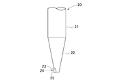
- 10 is a front view schematically showing an end mill according to Embodiment 6.
- FIG. It is explanatory drawing explaining the example 4 of a process by the same end mill. It is explanatory drawing explaining the example 5 of a process by the same end mill. It is explanatory drawing explaining the processing example by a round bar-shaped end mill with respect to the processing example 5.
- FIG. 10 is an enlarged front view showing the tip side of an end mill according to a modification of Example 6 in an enlarged manner. It is an enlarged right view which expands and shows the front end side of the end mill. It is an expansion perspective view which expands and shows the front end side of the end mill. 10 is a front view schematically showing an end mill according to Embodiment 7. FIG. It is explanatory drawing explaining the example 8 of a process by the end mill.
- FIG. 1 is a front view of a rotary cutting end mill 10 according to a first embodiment.
- the end mill 10 is in the shape of a round bar made of iron, and has a small-diameter main body 13 coaxially provided at the end of a large-diameter shank 11 via a conical connecting portion 12.
- a mounting recess 14 is provided.
- the main body 13 is, for example, a small-diameter round bar having a length of 10 mm and a diameter of 1.5 mm ⁇ , and a tooth body 15 is provided at the tip.
- a hemispherical cemented carbide tip forming a tooth body 15 is attached to the mounting recess 14, and a cutting edge 16 at the tip end of the tip swells in a semicircular shape so as to protrude from the outer peripheral surface of the main body 13.
- one tooth body 15 is provided at the tip of the main body 13 and has one cutting edge 16 at one place in the circumferential direction.
- One dimple is formed by one rotation of the main body 13.
- the shape of the cutting edge 16 is a semicircle having a low height 16a, a semicircle having a high height 16b, a triangle having a low height 16c, and a high height.
- a tall triangular shape 16d there are a tall triangular shape 16d, a trapezoidal shape 16e, a mountain-shaped shape 16f that swells in a curved shape, a mountain-shaped shape 16g that is recessed in a curved shape, a rectangular shape 16h, and the like.
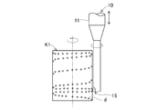
- a dimple processing example 1 by the end mill 10 will be described with reference to FIG.
- the outer peripheral surface of the cylindrical workpiece K1 is subjected to dimple processing.
- the end mill 10 is fixed to a rotation driving device (not shown) on the shank 11 side so as to be rotatable at a predetermined rotational speed and movable at a predetermined speed in the axial direction.
- the workpiece K1 has a cylindrical shape made of aluminum, and can be rotated at a predetermined rotational speed by a rotation driving device (not shown).
- dimple processing is performed in which dimples d spaced apart from each other are spirally arranged on the outer peripheral surface of the workpiece K1.
- the dimple d has a shape d1 to d8 according to the shape of the cutting edges 16a to 16h shown in FIGS. 3A to 3H.
- the workpiece K1 is fixed and can be processed even if the end mill 10 is moved.
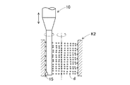
- processing example 2 will be described with reference to FIG.
- dimple processing is performed on the inner peripheral surface of the shaft hole of the cylindrical workpiece K2 having a cylindrical shaft hole.
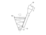
- processing example 3 will be described with reference to FIG.
- the outer peripheral surface of the truncated conical workpiece K3 is subjected to dimple processing.
- Dimple processing is performed on the outer peripheral surface of the workpiece K3 in a spiral shape.
- the workpieces K1, K2, and K3 are rotated by rotating the main body 13 while controlling at high speed. It is possible to form dimples in a desired arrangement at a high density on the concave and convex curved surface.
- the cylinder of the engine can be selected according to these characteristics. It can be suitably used for many applications such as inner and outer wall surfaces such as pistons and turbochargers, and joint surfaces of artificial joints.
- Example 1 it is desirable to perform surface treatment on the processed surface of the workpiece on which dimples are formed.
- surface treatment for example, chromium, nickel, titanium-based plating, PVD, CVD coating, diamond CVD, DLC, carbon, graphite, resin, molybdenum disulfide coating, and the like.
- the dimples are arranged in a spiral shape, but other arrangements such as a circle, a straight line, and a curve are also possible.
- the cutting edge 16k of Modification 1 includes a high circular chevron portion 16k1 on the front end side and a low semicircular chevron portion extending in the axial direction to the chevron portion 16k1 at the tip of the main body 13k. It consists of two parts of 16k2. As described above, the cutting edge 16k is formed of the high chevron portion 16k1 and the low chevron portion 16k2, so that the shape of the dimple formed is arranged at right angles to the rotation direction R as shown in FIG. 7B. A circular deep portion dk1 followed by a semicircular shallow portion dk2.
- the dimple dk into a deep and shallow dual structure, the effect of retaining the lubricating oil and the like of the dimple dk is enhanced, and as a result, the effect of reducing the friction of the processed surface is further enhanced.
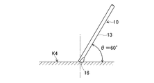
- the end mill 10 having a round bar shape of the main body 13 is arranged in parallel with the surface (contact surface) of the workpiece, but as shown in FIG. Cutting can be performed with the axis of the main body 13 inclined with respect to the surface (contact surface).
- the inclination angle ⁇ of the axis of the main body 13 with respect to the surface of the workpiece K4 is 60 °.
- the inclination angle ⁇ may be in the range of ⁇ 20 ° to + 75 °, and the diameter and depth of the dimples and the distance between the dimples can be adjusted within the inclination angle in this range.
- the end mill 10 ⁇ / b> A As shown in FIG. 9A, the end mill 10 ⁇ / b> A according to the second embodiment has one cutting edge 16 ⁇ / b> A at two locations facing each other across the axis as one tooth body 15 ⁇ / b> A provided at the tip of the main body 13 ⁇ / b> A. . According to the end mill 10A, since two dimples are formed in the rotation direction by one rotation of the main body 13A, it is possible to form a higher density dimple.
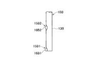
- the end mill 10B of the third embodiment is provided with two tooth bodies 15B1 and 15B2 at two positions separated in the axial direction of the main body 13B, and the tooth bodies 15B1 and 15B2 are respectively in the circumferential direction.
- One cutting edge 16B1 and 16B2 are provided at the same axial position at one location.
- one dimple can be formed at each of two locations separated in the axial direction by one rotation of the main body 13B.
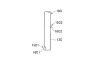
- the end mill 10C of Example 4 is provided with two tooth bodies 15C1 and 15C2 at two locations separated in the axial direction of the main body 13C, as shown in FIG. 9C.
- Each of the tooth bodies 15C1 and 15C2 has one cutting edge 16C1 and 16C2 at one position in the circumferential direction and at opposed positions sandwiching the axis. According to the end mill 10C, it is possible to form one dimple each having a shifted pitch at two locations separated in the rotational direction and the axial direction by one rotation of the main body 13C.
- the end mill 10D of the fifth embodiment is provided with two tooth bodies 15D1 and 15D2 at two locations separated in the axial direction of the main body 13D.
- Each tooth body 15D1 and 15D2 has two cutting edges 16D1 and 16D2 at two positions in the circumferential direction and at opposing positions sandwiching the axis.
- four dimples can be formed at positions separated in the axial direction and the circumferential direction by one rotation of the main body 13D.
- one cutting edge is provided on one of the two tooth bodies and two cutting bodies are provided on the other tooth body. It is also possible to provide a blade. In this case, three dimples are formed by rotating the main body once. Further, when two or more cutting edges are provided, they may have different cutting edge shapes. It becomes a dimple shape corresponding to each cutting edge shape.
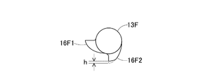
- one tooth body 15F provided on the front end side of the main body 13F is provided with two arcuate cutting edges 16F1 and 16F2 provided with two mounting grooves 14F interposed at two positions 90 ° apart in the circumferential direction.
- the cutting edge 16F1 on the front side in the rotational direction has an arc shape
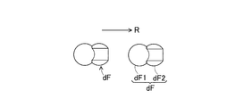
- the cutting edge 16F2 on the rear side in the rotational direction has a height h at the tip of the arc-shaped tip. Only the notch is flattened in the axial center. As a result, as shown in FIG.
- the dimple dF formed by the cutting edges 16F1 and 16F2 has a shape in which a semicircular deep recess dF1 and a shallow recess dF2 having a flat center in the axial direction are continuous in the rotation direction R. .
- the dimple dF having a shallow shallow double structure in the rotation direction R increases the effect of retaining the lubricating oil or the like of the dimple dF.
- the pressure between the contact surfaces is increased by the squeeze effect of the lubricating oil.
- the effect of lowering the friction of the processed surface can be further enhanced.
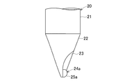
- the end mill 20 is provided with a frustoconical conical portion 22 constituting a main body together with a shank 21 which is inclined at a predetermined angle with respect to an axis and extends in a tapered manner at an end portion of a large-diameter shank 21 which also serves as a main body.
- one attachment recess 23 that is slightly recessed is provided at the tip of the conical portion 22.
- the tip of the conical portion 22 has a very small diameter, for example, a diameter of 3.0 mm.
- a hemispherical cemented carbide tip forming one tooth body 24 is attached to the mounting recess 23, and the cutting edge 25 at the tip of the tip swells into an arc shape having a radius of 1.5 mm, and the conical portion 22. It protrudes from the outer peripheral surface.
- the tooth body 24 has one cutting edge 25, and one dimple can be formed by one rotation of the conical portion 22.
- the shape of the cutting edge 25 can be the one shown in FIGS. 3A to 3H, the one shown in the first and second modifications, or the like.
- Example 4 of dimple processing by the end mill 20 will be described with reference to FIG.
- dimple processing is performed on the inner peripheral surface of an aluminum workpiece K5 having a cylindrical hole.
- the end mill 20 is fixed to a rotary drive device (not shown) on the shank 21 side, and is arranged in a state where the outer peripheral surface of the conical portion 22 is along the inner peripheral surface of the workpiece K5.
- the end mill 20 is rotatable at a predetermined rotational speed and is movable at a predetermined speed in the axial direction of the workpiece K5.
- the workpiece K5 can be rotated at a predetermined rotational speed by a rotation driving device (not shown).
- the shape of the dimple d is as described above.
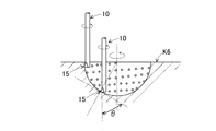
- Machining Example 5 is a process in which dimple processing is performed on the inner wall surface of the hole of the workpiece K6 having a hemispherical hole.
- the tip of the conical portion 22 of the end mill 20 is arranged so as to match the opening of the hole, and while rotating the workpiece K6 around the central axis, the end mill 20 is rotated in the axial direction, By inclining the axis of the end mill 20 along the bend from the position where the bend of the inner wall surface becomes large, the cutting edge 25 can be applied in accordance with the change in the bend of the hemisphere. As a result, the entire inner wall surface of the hemispherical hole can be dimple processed at a high density.
- the inner wall surface of the workpiece K6 has a concave hemispherical surface, and therefore, in the contact position between the conical portion 22 of the end mill 20 and the workpiece K6, the processing example 4 Unlike the above, the axis of the end mill 20 with respect to the contact surface (tangential plane) of the workpiece K6 is inclined at an inclination angle ⁇ .
- the inclination angle ⁇ is in the range of approximately 10 ° to 40 °, and appropriate dimples can be formed.
- end mill 20 since end mill 20 has strength secured by large-diameter shank portion 21, it is damaged even if a large force is applied to the main body portion by processing in an inclined state. There is little fear.
- the end mill 10 when the thin round bar-shaped end mill 10 as in Example 1 is used, as shown in FIG. 13B, the end mill 10 remains perpendicular to the depth of the hole in the workpiece K6.
- the inclination angle ⁇ increases beyond the range of about 0 ° to 75 °, and as the hole becomes deeper, the cutting edge cannot follow the bending of the hemispherical surface, and the dimple shape becomes non-uniform at the bottom. It becomes impossible to process. Further, when the end mill 10 is inclined in accordance with the change in the bending of the hole, there is a high possibility that the small diameter main body is damaged by applying a large force.
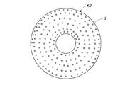
- dimple processing is performed on one surface of a thick disk-shaped workpiece K7 having a center hole.
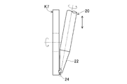
- the conical portion 22 of the end mill 20 set in the same manner as in the processing example 4 is arranged in accordance with one surface of the workpiece K7, and the workpiece K7 is rotated around the central axis while the end mill 20 is rotated at a constant speed.
- dimple processing is performed in which small circular dimples d are arranged in high density and spiral on one surface of the workpiece K7. Is done.
- FIG. 14 Another processing example 7 for one side of the thick disk-shaped workpiece K8 having a center hole by the end mill 20 will be described with reference to FIG.
- the processing form is the same as that shown in FIG. 14, but by increasing the shape of the cutting edge and shifting it while controlling the pitch of rotation, the dimple length is long and the circumferential direction as shown in FIG. 16.
- the dimples d arranged at equal intervals and curved in an arc shape with respect to the radial direction can be formed.
- the conical portion 22 is rotated while being controlled at a high speed.
- the tooth body 24 can be provided on the tip side of the conical portion 22, the diameter at the position of the tooth body 24 can be made extremely small while ensuring the strength of the end mill 20.
- dimples can be formed with a higher density, and dimples can be formed in a desired arrangement on the wall surface of the uneven surface shape or the inner wall surface of the deep hole. Furthermore, since the conical portion 22 of the end mill 20 has a sharp shape toward the tip, it is particularly effective for forming dimples on a concave curved surface.
- Example 6 since the sliding friction resistance and fluid resistance can be reduced and the wear resistance and heat dissipation can be improved with respect to the dimple formation surface, the engine cylinder can be selected according to these characteristics. It can be suitably applied to many uses such as inner and outer wall surfaces such as pistons and turbochargers, and joint surfaces of artificial joints.
- a surface treatment such as chromium plating on the processed surface of the workpiece K1 formed with dimples.
- the dimple arrangement is not limited to a spiral shape or a spiral shape, but may be a circular shape, a linear shape, a curved shape, or the like.
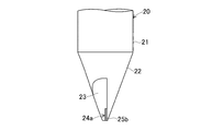
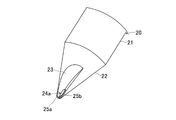
- a thin tip plate 24a made of a hard material such as single crystal diamond, polycrystalline diamond, CBN, cemented carbide, cermet or the like forming a tooth body is welded to the mounting recess 23 at the tip of the conical portion 22.
- the tip plate 24a is disposed so that a cutting edge 25a at one end swells in an arc shape having a radius of 1.5 mm and protrudes from the outer peripheral surface of the conical portion 22.
- the chip plate 24a has two flank surfaces 25b on one end side.
- the tip plate 24a is a thin plate and the flank 25b is formed in two stages, so that the formation of dimples by the cutting edge 25a is made clearer.
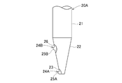
- the end mill 20A is similar to the end mill 20 in the shank 21 and the conical part 22, but in one place on the root side tooth body 24B in addition to one place on the tip side tooth body 24A along the axial direction of the conical part 22.
- Mounting recesses 23 and 26, each of which is slightly recessed, are provided.
- one hemispherical cemented carbide tip forming each of the tooth bodies 24A and 24B is mounted, and the cutting edges 25A and 25B at the tips of the tips swell in an arc shape to form a cone. It is arranged so as to protrude from the outer peripheral surface of the portion 22.
- the end mill 20A is provided with two tooth bodies 24A and 24B at two locations separated in the axial direction of the conical portion 22 in the same manner as the end mill 10B of the third embodiment.
- One cutting edge 25A, 25B is provided at one position in the direction and at the same axial position.
- one dimple can be formed at each of two locations separated in the axial direction by one rotation of the end mill 20A.
- Example 8 of dimple processing by the end mill 20A will be described with reference to FIG.
- dimple processing is performed on the inner peripheral surface of the aluminum workpiece K9 having a cylindrical hole.
- the end mill 20A is fixed to a rotary drive device (not shown) on the shank 21 side, and is arranged in a state where the outer peripheral surface of the conical portion 22 is in contact with the inner peripheral surface of the workpiece K9.
- the end mill 20 is rotatable at a predetermined rotational speed and is movable at a predetermined speed in the axial direction of the workpiece K9.
- the workpiece K9 is made rotatable at a predetermined rotational speed by a rotation driving device (not shown).
- the circular dimple da by the cutting edge 25A on the tip side and the cutting edge on the root side are moved on the inner peripheral surface of the workpiece K9.
- the rod-shaped dimple db of 25B is applied in two rows spirally apart in the axial direction.
- each tooth body 24A and 24B can be provided with two cutting edges respectively opposed to the axis.
- the workpiece in addition to the rotation of the end mill and the movement in the axial direction, the workpiece is also rotated.
- the end mill is mounted on a drive control device such as an articulated robot.
- the axis of the main body can be freely moved according to the surface shape of the workpiece while rotating about the axis.
- dimple processing can be performed on the workpiece having various uneven curved surfaces only by driving the main body while the workpiece is fixed, so that dimple processing can be performed more easily and with high accuracy.
- a large apparatus for rotating a large workpiece is not necessary.
- an end mill to which a chip is attached in the description of each of the above embodiments, it may be a cemented carbide end mill or a coated end mill. Alternatively, a PCD or CBN chip may be brazed.
- Example 8 In each of the above embodiments, an end mill is shown in which a chip is attached to the outer peripheral surface of the main body. However, in this embodiment, a spherical cutting edge is provided as an end mill on the end surface of a rod-shaped main body (not shown). It is a ball end mill. As described above, by using the ball end mill, dimples spaced from each other can be formed on the surface of the workpiece as in the above-described embodiment.
Landscapes
- Engineering & Computer Science (AREA)
- Mechanical Engineering (AREA)
- Milling Processes (AREA)
- Circuit Arrangement For Electric Light Sources In General (AREA)
- Dc Digital Transmission (AREA)
Abstract
Priority Applications (6)
| Application Number | Priority Date | Filing Date | Title |
|---|---|---|---|
| EP16817438.1A EP3315233A4 (fr) | 2015-06-29 | 2016-06-21 | Procédé d'embrèvement utilisant une fraise en bout, et fraise en bout |
| JP2017526166A JP6637499B2 (ja) | 2015-06-29 | 2016-06-21 | フライスによるディンプル加工方法及びフライス |
| CN201680030429.2A CN107614170B (zh) | 2015-06-29 | 2016-06-21 | 基于立铣刀的凹坑加工方法以及立铣刀 |
| MX2017016459A MX2017016459A (es) | 2015-06-29 | 2016-06-21 | Metodo de procesamiento de indentaciones por medio de fresado de extremos. |
| KR1020177034914A KR102425458B1 (ko) | 2015-06-29 | 2016-06-21 | 엔드 밀에 의한 딤플 가공 방법 및 엔드 밀 |
| US15/580,023 US10857602B2 (en) | 2015-06-29 | 2016-06-21 | Dimples processing method by means of end milling and end mill |
Applications Claiming Priority (4)
| Application Number | Priority Date | Filing Date | Title |
|---|---|---|---|
| JP2015-129871 | 2015-06-29 | ||
| JP2015129871 | 2015-06-29 | ||
| JP2016-035790 | 2016-02-26 | ||
| JP2016035790 | 2016-02-26 |
Publications (1)
| Publication Number | Publication Date |
|---|---|
| WO2017002326A1 true WO2017002326A1 (fr) | 2017-01-05 |
Family
ID=57608027
Family Applications (1)
| Application Number | Title | Priority Date | Filing Date |
|---|---|---|---|
| PCT/JP2016/002982 Ceased WO2017002326A1 (fr) | 2015-06-29 | 2016-06-21 | Procédé d'embrèvement utilisant une fraise en bout, et fraise en bout |
Country Status (7)
| Country | Link |
|---|---|
| US (1) | US10857602B2 (fr) |
| EP (1) | EP3315233A4 (fr) |
| JP (1) | JP6637499B2 (fr) |
| KR (1) | KR102425458B1 (fr) |
| CN (1) | CN107614170B (fr) |
| MX (1) | MX2017016459A (fr) |
| WO (1) | WO2017002326A1 (fr) |
Cited By (7)
| Publication number | Priority date | Publication date | Assignee | Title |
|---|---|---|---|---|
| WO2018130730A1 (fr) * | 2017-01-16 | 2018-07-19 | Xam Mar Mangrane Esteban | Outil de fraisage d'une superstructure dentaire |
| WO2019202911A1 (fr) * | 2018-04-18 | 2019-10-24 | 兼房株式会社 | Pièce alvéolée et procédé d'alvéolage |
| JP2020508886A (ja) * | 2017-02-14 | 2020-03-26 | スリーエム イノベイティブ プロパティズ カンパニー | 微細構造を製造するためのエンドミル加工法、微細構造を含むツール、及び微細構造 |
| JP2020085024A (ja) * | 2018-11-16 | 2020-06-04 | 日本製鉄株式会社 | 回転軸受及び回転軸受の製造方法 |
| JPWO2021049260A1 (fr) * | 2019-09-13 | 2021-03-18 | ||
| JPWO2023021903A1 (fr) * | 2021-08-18 | 2023-02-23 | ||
| JP7523001B1 (ja) | 2024-03-26 | 2024-07-26 | マイクロ・ダイヤモンド株式会社 | 単結晶ダイヤモンドマイクロエンドミル |
Families Citing this family (7)
| Publication number | Priority date | Publication date | Assignee | Title |
|---|---|---|---|---|
| US11027341B2 (en) * | 2016-01-06 | 2021-06-08 | Kanefusa Kabushiki Kaisha | Dimple processing method using rotary cutting tool, and rotary cutting tool for dimple processing |
| CZ307969B6 (cs) * | 2018-08-02 | 2019-09-18 | ÄŚeskĂ© vysokĂ© uÄŤenĂ technickĂ© v Praze | Diamantový rotační obráběcí nástroj pro třískové obrábění a způsob jeho výroby |
| KR102793731B1 (ko) * | 2019-02-13 | 2025-04-09 | 닛토덴코 가부시키가이샤 | 광학 필름의 제조 방법 |
| JP6723623B1 (ja) * | 2019-08-05 | 2020-07-15 | 登茂二 翁 | 切削加工方法 |
| WO2021084727A1 (fr) * | 2019-10-31 | 2021-05-06 | 株式会社Ibuki | Procédé de réparation d'un moule, et moule |
| IT202000024883A1 (it) * | 2020-10-21 | 2022-04-21 | Rc Stampi Di Roberto Campanini | Sistema di realizzazione per stampi per prodotti cosmetici colati, metodo e stampo |
| CN117791266B (zh) * | 2024-01-18 | 2024-11-08 | 东莞市维康汽车电子有限公司 | 连接器用中心针的制作工艺 |
Citations (9)
| Publication number | Priority date | Publication date | Assignee | Title |
|---|---|---|---|---|
| US3841199A (en) * | 1973-03-13 | 1974-10-15 | Acushnet Co | Golf ball dimple milling apparatus |
| JPH0811223A (ja) * | 1994-06-30 | 1996-01-16 | Canon Inc | 光学素子及びその成形方法 |
| JPH1052998A (ja) * | 1996-08-08 | 1998-02-24 | Kanefusa Kk | 回転切削工具による被加工材表面の加飾方法 |
| JP2002205310A (ja) * | 2000-10-31 | 2002-07-23 | Eastman Kodak Co | マイクロレンズアレー用モールド型を製造する方法 |
| JP2002361510A (ja) * | 2001-06-07 | 2002-12-18 | Masami Masuda | 微細凹面のミーリング加工法とその装置 |
| JP2004009158A (ja) * | 2002-06-04 | 2004-01-15 | Sumitomo Rubber Ind Ltd | ゴルフボール用金型の製造方法 |
| JP2005212015A (ja) * | 2004-01-28 | 2005-08-11 | Fuji Photo Film Co Ltd | 切削工具 |
| JP2008246587A (ja) * | 2007-03-29 | 2008-10-16 | Nagasaki Prefecture | フライス加工の加工制御方法 |
| US20150056036A1 (en) * | 2012-03-30 | 2015-02-26 | Makino Milling Machine Co., Ltd. | Workpiece machining method, machine tool, tool path-generating device and tool path-generating program |
Family Cites Families (54)
| Publication number | Priority date | Publication date | Assignee | Title |
|---|---|---|---|---|
| US3103736A (en) * | 1959-05-11 | 1963-09-17 | Stanray Corp | Cutting tool and milling head insert therefor |
| US4028992A (en) * | 1975-11-20 | 1977-06-14 | Kuehnle Manfred R | Method and means for making helical races |
| JPS5331286A (en) * | 1976-09-02 | 1978-03-24 | Riyousuke Hosoi | Ball end mill |
| US4252480A (en) * | 1979-05-03 | 1981-02-24 | Sumitomo Electric Industries, Ltd. | Throw away insert and end mills |
| US4411564A (en) * | 1981-10-19 | 1983-10-25 | The Ingersoll Milling Machine Company | Indexable cutting insert having radiused cutting edges |
| DE3706282A1 (de) * | 1986-02-28 | 1987-09-03 | Izumo Sangyo Kk | Umlaufendes schneidwerkzeug |
| US4868961A (en) * | 1987-01-20 | 1989-09-26 | Coleman-Frizzell, Inc. | Apparatus for engraving vein cuts |
| US4781049A (en) * | 1987-01-20 | 1988-11-01 | Coleman-Frizzell, Inc. | Apparatus for creating a florentine pattern on a gold strip |
| US5094573A (en) * | 1988-07-21 | 1992-03-10 | Hougen Everett D | Multidirectional cutting tool |
| JPH02295573A (ja) * | 1989-05-09 | 1990-12-06 | Sumitomo Rubber Ind Ltd | 低飛距離ゴルフボール |
| US4954022A (en) * | 1989-06-16 | 1990-09-04 | Underwood Mold Co., Inc. | Method for machining multiple cuts in a workpiece to a uniform depth |
| US5387061A (en) * | 1990-12-14 | 1995-02-07 | The United States Of America As Represented By The United States Department Of Energy | Parameter monitoring compensation system and method |
| US5213456A (en) * | 1991-09-19 | 1993-05-25 | Lee Valley Tools, Ltd. | Plug cutter |
| US5197361A (en) * | 1991-10-11 | 1993-03-30 | General Electric Company | Surface contouring tool |
| TW221383B (fr) * | 1992-06-08 | 1994-03-01 | Sumitomo Gomo Kogyo Kk | |
| IL108115A (en) * | 1993-12-21 | 1997-02-18 | Iscar Ltd | Chip cutting tool |
| US5681134A (en) * | 1994-11-19 | 1997-10-28 | Wolfcraft Gmbh | Device for cutting frustoconical plugs from a board |
| US5788435A (en) * | 1995-04-28 | 1998-08-04 | Mccarthy; John F. | Automated diamond cutter apparatus |
| US5720676A (en) * | 1995-07-25 | 1998-02-24 | Bridgestone Sports Co., Ltd. | Golf ball |
| DE19529786C1 (de) * | 1995-08-12 | 1997-03-06 | Loh Optikmaschinen Ag | Verfahren und Werkzeug zur Erzeugung einer konkaven Oberfläche an einem Brillenglasrohling |
| US6012882A (en) * | 1995-09-12 | 2000-01-11 | Turchan; Manuel C. | Combined hole making, threading, and chamfering tool with staggered thread cutting teeth |
| US6224299B1 (en) * | 1997-10-20 | 2001-05-01 | Laszlo Frecska | Tool with straight inserts for providing helical cutting action |
| US6565297B2 (en) * | 1998-04-17 | 2003-05-20 | M. Norbert Schmitt | Method of milling large thread lengths |
| IL124328A (en) * | 1998-05-05 | 2003-12-10 | Iscar Ltd | Cutting tool assembly and cutting insert therefor |
| SE517447C2 (sv) * | 1999-06-29 | 2002-06-04 | Seco Tools Ab | Gängfräs med därför avsett skär |
| JP4116224B2 (ja) | 2000-03-23 | 2008-07-09 | ローム株式会社 | レンズアレイの製造方法 |
| US6390740B1 (en) * | 2000-10-03 | 2002-05-21 | Spalding Sports Worldwide, Inc. | Non-circular dimples formed via an orbital pantograph cutter |
| DE10104580B4 (de) * | 2001-02-01 | 2005-03-03 | Gebr. Brasseler Gmbh & Co. Kg | Fräswerkzeug |
| JP2003084370A (ja) * | 2001-09-12 | 2003-03-19 | Masami Masuda | 異方性ディンプル面 |
| JP2003236809A (ja) * | 2002-02-13 | 2003-08-26 | Nisshin Mokuzai Kogyo Kk | 木質材等の表面加工法及び表面加工された木質材 |
| US6726413B1 (en) * | 2002-12-16 | 2004-04-27 | Goodrich Corporation | Contour plunge milling |
| KR101093461B1 (ko) * | 2002-12-26 | 2011-12-13 | 미쓰비시 마테리알 가부시키가이샤 | 레디어스 엔드밀 |
| DE102004011297A1 (de) * | 2004-03-09 | 2005-09-22 | NUBIUS GROUP Präzisionswerkzeuge GmbH | Bohr- und Fräswerkzeug zur rotierenden spanabhebenden Bearbeitung von Werkstoffen |
| JP4103876B2 (ja) * | 2004-09-17 | 2008-06-18 | 日産自動車株式会社 | 溶射前処理方法およびエンジンのシリンダブロックならびに溶射前処理装置 |
| JP4059246B2 (ja) * | 2004-12-10 | 2008-03-12 | 日産自動車株式会社 | 粗面化加工方法および切削工具 |
| US9575485B2 (en) * | 2006-07-25 | 2017-02-21 | Mori Seiki Co., Ltd. | Compound machining method and apparatus |
| EP1927444B1 (fr) * | 2006-12-01 | 2012-08-15 | Kälin & Co. AG | Lame de rabot |
| SE530527C2 (sv) | 2007-02-08 | 2008-07-01 | Seco Tools Ab | Skärverktyg med multipla kanaler som definierar olika profiler samt metod |
| DE102007010163A1 (de) | 2007-02-28 | 2008-09-04 | Sandvik Intellectual Property Ab | Kugelkopffräser |
| DE202007010616U1 (de) | 2007-07-31 | 2007-09-27 | Zecha Hartmetall-Werkzeugfabrikation Gmbh | Gewindefräser |
| JP2010036277A (ja) | 2008-08-01 | 2010-02-18 | Nakayama Mokkosho:Kk | 木材へのネジ形成方法と、ネジ付き木材と、木材の接合構造 |
| EP2213399A1 (fr) | 2009-01-28 | 2010-08-04 | VARGUS Ltd. | Insert de coupe triangulaire et support d'outil associé |
| DE102009027200B3 (de) * | 2009-06-25 | 2011-04-07 | Ford Global Technologies, LLC, Dearborn | Verfahren zum Aufrauhen von Metalloberflächen, Verwendung des Verfahrens und Werkstück |
| WO2011055627A1 (fr) * | 2009-11-05 | 2011-05-12 | コニカミノルタオプト株式会社 | Outil de découpe, procédé de fabrication de matrice de moulage, et matrice de moulage pour objectif à réseau |
| DE102009052642A1 (de) * | 2009-11-10 | 2011-05-12 | Timura Holzmanufaktur Gmbh | Verfahren zum Herstellen einer strukturierten, Erhöhungen und Vertiefungen aufweisenden Oberfläche an einem Werkstück aus Holz |
| IL204008A (en) * | 2010-02-17 | 2014-02-27 | Iscar Ltd | Tool connection |
| US8550941B2 (en) * | 2010-12-02 | 2013-10-08 | Nike, Inc. | Systems and methods for evaluating a golf ball design |
| US8991287B2 (en) * | 2012-07-06 | 2015-03-31 | Caterpillar Inc. | Surface dimpling on rotating work piece using rotation cutting tool |
| CN203109327U (zh) | 2013-01-29 | 2013-08-07 | 郑州市钻石精密制造有限公司 | 一种焊接金刚石刀头的球头铣刀 |
| CN203304662U (zh) | 2013-05-29 | 2013-11-27 | 苏州富莱克精密工具有限公司 | 一种双面倒角铣刀 |
| DK3064369T3 (da) * | 2013-11-01 | 2020-07-13 | Kanefusa Knife & Saw | Fremgangsmåde til at forarbejde overflade af arbejdsstykke ved anvendelse af roterende skæreværktøj |
| DE202013105739U1 (de) | 2013-12-17 | 2014-01-29 | Mimatic Gmbh | Miniaturfräser |
| US11027341B2 (en) * | 2016-01-06 | 2021-06-08 | Kanefusa Kabushiki Kaisha | Dimple processing method using rotary cutting tool, and rotary cutting tool for dimple processing |
| WO2017199911A1 (fr) * | 2016-05-19 | 2017-11-23 | 兼房株式会社 | Procédé de formation de dépressions grâce à un outil de coupe rotatif |
-
2016
- 2016-06-21 EP EP16817438.1A patent/EP3315233A4/fr not_active Withdrawn
- 2016-06-21 US US15/580,023 patent/US10857602B2/en active Active
- 2016-06-21 CN CN201680030429.2A patent/CN107614170B/zh active Active
- 2016-06-21 JP JP2017526166A patent/JP6637499B2/ja active Active
- 2016-06-21 WO PCT/JP2016/002982 patent/WO2017002326A1/fr not_active Ceased
- 2016-06-21 KR KR1020177034914A patent/KR102425458B1/ko not_active Expired - Fee Related
- 2016-06-21 MX MX2017016459A patent/MX2017016459A/es unknown
Patent Citations (9)
| Publication number | Priority date | Publication date | Assignee | Title |
|---|---|---|---|---|
| US3841199A (en) * | 1973-03-13 | 1974-10-15 | Acushnet Co | Golf ball dimple milling apparatus |
| JPH0811223A (ja) * | 1994-06-30 | 1996-01-16 | Canon Inc | 光学素子及びその成形方法 |
| JPH1052998A (ja) * | 1996-08-08 | 1998-02-24 | Kanefusa Kk | 回転切削工具による被加工材表面の加飾方法 |
| JP2002205310A (ja) * | 2000-10-31 | 2002-07-23 | Eastman Kodak Co | マイクロレンズアレー用モールド型を製造する方法 |
| JP2002361510A (ja) * | 2001-06-07 | 2002-12-18 | Masami Masuda | 微細凹面のミーリング加工法とその装置 |
| JP2004009158A (ja) * | 2002-06-04 | 2004-01-15 | Sumitomo Rubber Ind Ltd | ゴルフボール用金型の製造方法 |
| JP2005212015A (ja) * | 2004-01-28 | 2005-08-11 | Fuji Photo Film Co Ltd | 切削工具 |
| JP2008246587A (ja) * | 2007-03-29 | 2008-10-16 | Nagasaki Prefecture | フライス加工の加工制御方法 |
| US20150056036A1 (en) * | 2012-03-30 | 2015-02-26 | Makino Milling Machine Co., Ltd. | Workpiece machining method, machine tool, tool path-generating device and tool path-generating program |
Non-Patent Citations (1)
| Title |
|---|
| See also references of EP3315233A4 * |
Cited By (12)
| Publication number | Priority date | Publication date | Assignee | Title |
|---|---|---|---|---|
| WO2018130730A1 (fr) * | 2017-01-16 | 2018-07-19 | Xam Mar Mangrane Esteban | Outil de fraisage d'une superstructure dentaire |
| JP2020508886A (ja) * | 2017-02-14 | 2020-03-26 | スリーエム イノベイティブ プロパティズ カンパニー | 微細構造を製造するためのエンドミル加工法、微細構造を含むツール、及び微細構造 |
| WO2019202911A1 (fr) * | 2018-04-18 | 2019-10-24 | 兼房株式会社 | Pièce alvéolée et procédé d'alvéolage |
| CN111989501A (zh) * | 2018-04-18 | 2020-11-24 | 兼房株式会社 | 带凹部的工件及凹部的加工方法 |
| JP2020085024A (ja) * | 2018-11-16 | 2020-06-04 | 日本製鉄株式会社 | 回転軸受及び回転軸受の製造方法 |
| JP7176367B2 (ja) | 2018-11-16 | 2022-11-22 | 日本製鉄株式会社 | 回転軸受及び回転軸受の製造方法 |
| JPWO2021049260A1 (fr) * | 2019-09-13 | 2021-03-18 | ||
| WO2021049260A1 (fr) * | 2019-09-13 | 2021-03-18 | 兼房株式会社 | Procédé d'usinage de fossette |
| JPWO2023021903A1 (fr) * | 2021-08-18 | 2023-02-23 | ||
| WO2023021903A1 (fr) * | 2021-08-18 | 2023-02-23 | 兼房株式会社 | Procédé d'usinage d'alvéole |
| JP7523001B1 (ja) | 2024-03-26 | 2024-07-26 | マイクロ・ダイヤモンド株式会社 | 単結晶ダイヤモンドマイクロエンドミル |
| JP2025149406A (ja) * | 2024-03-26 | 2025-10-08 | マイクロ・ダイヤモンド株式会社 | 単結晶ダイヤモンドマイクロエンドミル |
Also Published As
| Publication number | Publication date |
|---|---|
| EP3315233A1 (fr) | 2018-05-02 |
| MX2017016459A (es) | 2019-05-30 |
| JP6637499B2 (ja) | 2020-01-29 |
| US10857602B2 (en) | 2020-12-08 |
| EP3315233A4 (fr) | 2019-05-01 |
| KR102425458B1 (ko) | 2022-07-25 |
| KR20180020968A (ko) | 2018-02-28 |
| CN107614170A (zh) | 2018-01-19 |
| US20180154461A1 (en) | 2018-06-07 |
| JPWO2017002326A1 (ja) | 2018-04-19 |
| CN107614170B (zh) | 2019-06-18 |
Similar Documents
| Publication | Publication Date | Title |
|---|---|---|
| WO2017002326A1 (fr) | Procédé d'embrèvement utilisant une fraise en bout, et fraise en bout | |
| JP6679620B2 (ja) | 回転切削工具を用いたディンプル加工方法及びディンプル加工用回転切削工具 | |
| JP4956529B2 (ja) | 正弦角度付けした回転切削工具 | |
| US10702931B2 (en) | Dimple processing method using rotary cutting tool | |
| JP6309968B2 (ja) | 矩形または長方形のスティックブレードの径方向調整能力を持つ歯切工具 | |
| JP2009525197A (ja) | 切削インサート | |
| JP3226162U (ja) | 切削エンドミル | |
| CN111989501B (zh) | 带凹部的工件及凹部的加工方法 | |
| JP6723623B1 (ja) | 切削加工方法 | |
| RS56962B1 (sr) | Alat okruglog oblika za obradu radnog komada | |
| WO2021049260A1 (fr) | Procédé d'usinage de fossette | |
| JP2008229764A (ja) | 回転工具及び加工方法 | |
| FI110017B (fi) | Tiehöylän terä | |
| EP4205891A1 (fr) | Insert de raclage pour une fraise rotative de lissage | |
| JP2015229221A (ja) | バニシング工具、バニシング加工装置およびバニシング加工方法 | |
| JP2014159050A (ja) | 切削工具 |
Legal Events
| Date | Code | Title | Description |
|---|---|---|---|
| 121 | Ep: the epo has been informed by wipo that ep was designated in this application |
Ref document number: 16817438 Country of ref document: EP Kind code of ref document: A1 |
|
| ENP | Entry into the national phase |
Ref document number: 2017526166 Country of ref document: JP Kind code of ref document: A |
|
| ENP | Entry into the national phase |
Ref document number: 20177034914 Country of ref document: KR Kind code of ref document: A |
|
| WWE | Wipo information: entry into national phase |
Ref document number: 15580023 Country of ref document: US |
|
| WWE | Wipo information: entry into national phase |
Ref document number: MX/A/2017/016459 Country of ref document: MX |
|
| NENP | Non-entry into the national phase |
Ref country code: DE |
|
| WWE | Wipo information: entry into national phase |
Ref document number: 2016817438 Country of ref document: EP |