WO2017010441A1 - アタッチメントの連結装置 - Google Patents
アタッチメントの連結装置 Download PDFInfo
- Publication number
- WO2017010441A1 WO2017010441A1 PCT/JP2016/070371 JP2016070371W WO2017010441A1 WO 2017010441 A1 WO2017010441 A1 WO 2017010441A1 JP 2016070371 W JP2016070371 W JP 2016070371W WO 2017010441 A1 WO2017010441 A1 WO 2017010441A1
- Authority
- WO
- WIPO (PCT)
- Prior art keywords
- attachment
- connecting device
- hole
- alignment
- strut
- Prior art date
- Legal status (The legal status is an assumption and is not a legal conclusion. Google has not performed a legal analysis and makes no representation as to the accuracy of the status listed.)
- Ceased
Links
Images



Classifications
-
- B—PERFORMING OPERATIONS; TRANSPORTING
- B66—HOISTING; LIFTING; HAULING
- B66C—CRANES; LOAD-ENGAGING ELEMENTS OR DEVICES FOR CRANES, CAPSTANS, WINCHES, OR TACKLES
- B66C23/00—Cranes comprising essentially a beam, boom, or triangular structure acting as a cantilever and mounted for translatory of swinging movements in vertical or horizontal planes or a combination of such movements, e.g. jib-cranes, derricks, tower cranes
- B66C23/18—Cranes comprising essentially a beam, boom, or triangular structure acting as a cantilever and mounted for translatory of swinging movements in vertical or horizontal planes or a combination of such movements, e.g. jib-cranes, derricks, tower cranes specially adapted for use in particular purposes
- B66C23/26—Cranes comprising essentially a beam, boom, or triangular structure acting as a cantilever and mounted for translatory of swinging movements in vertical or horizontal planes or a combination of such movements, e.g. jib-cranes, derricks, tower cranes specially adapted for use in particular purposes for use on building sites; constructed, e.g. with separable parts, to facilitate rapid assembly or dismantling, for operation at successively higher levels, for transport by road or rail
- B66C23/34—Self-erecting cranes, i.e. with hoisting gear adapted for crane erection purposes
- B66C23/344—Self-erecting cranes, i.e. with hoisting gear adapted for crane erection purposes adapted for transport purposes
-
- F—MECHANICAL ENGINEERING; LIGHTING; HEATING; WEAPONS; BLASTING
- F16—ENGINEERING ELEMENTS AND UNITS; GENERAL MEASURES FOR PRODUCING AND MAINTAINING EFFECTIVE FUNCTIONING OF MACHINES OR INSTALLATIONS; THERMAL INSULATION IN GENERAL
- F16B—DEVICES FOR FASTENING OR SECURING CONSTRUCTIONAL ELEMENTS OR MACHINE PARTS TOGETHER, e.g. NAILS, BOLTS, CIRCLIPS, CLAMPS, CLIPS OR WEDGES; JOINTS OR JOINTING
- F16B7/00—Connections of rods or tubes, e.g. of non-circular section, mutually, including resilient connections
- F16B7/04—Clamping or clipping connections
- F16B7/0433—Clamping or clipping connections for rods or tubes being in parallel relationship
-
- B—PERFORMING OPERATIONS; TRANSPORTING
- B66—HOISTING; LIFTING; HAULING
- B66C—CRANES; LOAD-ENGAGING ELEMENTS OR DEVICES FOR CRANES, CAPSTANS, WINCHES, OR TACKLES
- B66C23/00—Cranes comprising essentially a beam, boom, or triangular structure acting as a cantilever and mounted for translatory of swinging movements in vertical or horizontal planes or a combination of such movements, e.g. jib-cranes, derricks, tower cranes
- B66C23/18—Cranes comprising essentially a beam, boom, or triangular structure acting as a cantilever and mounted for translatory of swinging movements in vertical or horizontal planes or a combination of such movements, e.g. jib-cranes, derricks, tower cranes specially adapted for use in particular purposes
- B66C23/26—Cranes comprising essentially a beam, boom, or triangular structure acting as a cantilever and mounted for translatory of swinging movements in vertical or horizontal planes or a combination of such movements, e.g. jib-cranes, derricks, tower cranes specially adapted for use in particular purposes for use on building sites; constructed, e.g. with separable parts, to facilitate rapid assembly or dismantling, for operation at successively higher levels, for transport by road or rail
-
- B—PERFORMING OPERATIONS; TRANSPORTING
- B66—HOISTING; LIFTING; HAULING
- B66C—CRANES; LOAD-ENGAGING ELEMENTS OR DEVICES FOR CRANES, CAPSTANS, WINCHES, OR TACKLES
- B66C23/00—Cranes comprising essentially a beam, boom, or triangular structure acting as a cantilever and mounted for translatory of swinging movements in vertical or horizontal planes or a combination of such movements, e.g. jib-cranes, derricks, tower cranes
- B66C23/18—Cranes comprising essentially a beam, boom, or triangular structure acting as a cantilever and mounted for translatory of swinging movements in vertical or horizontal planes or a combination of such movements, e.g. jib-cranes, derricks, tower cranes specially adapted for use in particular purposes
- B66C23/26—Cranes comprising essentially a beam, boom, or triangular structure acting as a cantilever and mounted for translatory of swinging movements in vertical or horizontal planes or a combination of such movements, e.g. jib-cranes, derricks, tower cranes specially adapted for use in particular purposes for use on building sites; constructed, e.g. with separable parts, to facilitate rapid assembly or dismantling, for operation at successively higher levels, for transport by road or rail
- B66C23/34—Self-erecting cranes, i.e. with hoisting gear adapted for crane erection purposes
- B66C23/346—Self-erecting cranes, i.e. with hoisting gear adapted for crane erection purposes with locking devices
-
- B—PERFORMING OPERATIONS; TRANSPORTING
- B66—HOISTING; LIFTING; HAULING
- B66C—CRANES; LOAD-ENGAGING ELEMENTS OR DEVICES FOR CRANES, CAPSTANS, WINCHES, OR TACKLES
- B66C23/00—Cranes comprising essentially a beam, boom, or triangular structure acting as a cantilever and mounted for translatory of swinging movements in vertical or horizontal planes or a combination of such movements, e.g. jib-cranes, derricks, tower cranes
- B66C23/62—Constructional features or details
- B66C23/64—Jibs
- B66C23/68—Jibs foldable or otherwise adjustable in configuration
-
- B—PERFORMING OPERATIONS; TRANSPORTING
- B66—HOISTING; LIFTING; HAULING
- B66C—CRANES; LOAD-ENGAGING ELEMENTS OR DEVICES FOR CRANES, CAPSTANS, WINCHES, OR TACKLES
- B66C2700/00—Cranes
- B66C2700/03—Cranes with arms or jibs; Multiple cranes
- B66C2700/0321—Travelling cranes
- B66C2700/0357—Cranes on road or off-road vehicles, on trailers or towed vehicles; Cranes on wheels or crane-trucks
- B66C2700/0378—Construction details related to the travelling, to the supporting of the crane or to the blocking of the axles; Outriggers; Coupling of the travelling mechamism to the crane mechanism
Definitions
- the present invention relates to a connecting device used when a plurality of long attachments such as struts constituting a work machine such as a crawler crane are stacked up and down.
- Patent Documents 1 and 2 there are those described in Patent Documents 1 and 2 below.
- connecting tools called fork ends and eye ends are fixed to opposing portions of a front mast and a rear mast that are stacked one above the other, and these connecting tools are connected by pins.
- lugs are respectively fixed to opposing portions of the intermediate boom that are stacked up and down, and these lugs are connected by a connecting pin.
- the above-described conventional technology has the following problems. Since the attachment fixing methods described in Patent Documents 1 and 2 both fix and pin a coupling tool such as a lug to the facing portion of the attachment stacked vertically, the height of the coupling tool is high. For some reason, the transportation height will be high.
- the present invention has been made in view of the above circumstances, and an object of the present invention is to reduce a height dimension when a plurality of long attachments constituting a work machine are stacked and fixed to each other, as compared with the prior art. It is an object to provide an attachment connecting device.
- the connecting device connects the first attachment and the second attachment constituting the work machine to each other.
- the connecting device includes a first connected part, a second connected part, and a connecting member.
- the first coupled portion extends outward from a first side surface extending along the longitudinal direction of the first attachment.
- the second connected portion extends outward from a second side surface extending along the longitudinal direction of the second attachment, and the first attachment and the second attachment are stacked on the first attachment.
- the first connection portion is disposed so as to face each other.
- the connecting member connects the first connected portion and the second connected portion.
- the height of the connecting device is determined by a plurality of long attachments constituting the work machine. Almost no effect on height when stacked vertically and fixed to each other. That is, the height dimension when the attachments are stacked vertically and fixed to each other is reduced as compared with the prior art.
- FIG. 2 is a cross-sectional view taken along the line AA in FIG. 1 and shows a state in which a connecting member is not mounted. It is a perspective view of the connection instrument of the connection apparatus shown in FIG. It is a perspective view of the position alignment part of the coupling device shown in FIG. It is a side view showing the state where a plurality of struts stacked up and down were connected by the connecting device concerning a 2nd embodiment of the present invention. It is the B section enlarged view of FIG.
- a luffing jib crane (not shown) that is a work machine (a crane with a jib attached to the tip of a boom) is disassembled and transported.
- the connecting device of the present invention provided on a long attachment constituting the crane can be used.
- the long attachment include struts, jibs, booms, and masts.
- FIG. 1 is a side view showing a state in which a plurality of struts stacked vertically are connected by a connecting device according to a first embodiment of the present invention.
- the long attachment constituting the luffing jib crane is disassembled and loaded on the trailer 50 in the form shown in FIG. 1, for example, and transported.
- the lower jib 2 shown in FIG. 1 constitutes the lower part of the jib attached to the tip of the boom (not shown) of the luffing jib crane.
- the front strut 3 shown by FIG. 1 comprises the 1st attachment of this invention
- the rear strut 4 comprises the 2nd attachment of this invention.
- Each of the front strut 3 and the rear strut 4 is rotatably attached to the tip of the jib of the luffing jib crane.
- the front strut 3 attached to the lower jib 2 via the pin 3A is folded on the lower jib 2
- the rear strut 4 is stacked on the front strut 3, so that the lower jib 2, front strut 3 and the rear strut 4 are transported together in one trailer 50.
- a posture in which the rear strut 4 is stacked on the front strut 3 is defined as a connected posture of the front strut 3 and the rear strut 4.
- the connecting device includes a connecting device 1.
- the front strut 3 and the rear strut 4 are connected to each other by a connecting device 1. It is desirable that a plurality of the connecting devices 1 be arranged at a predetermined interval in the longitudinal direction of the strut.
- the connecting devices 1 are arranged on the side surfaces of both ends in the longitudinal direction of the strut.
- the connection tool 1 is arrange
- the alignment portion 7 is disposed on the side surface of the strut and in the vicinity of each connection device 1 (with a predetermined space between the connection devices 1). Similar to the connecting device 1, the alignment portions 7 are arranged on both sides of the strut in the width direction, that is, a total of four alignment portions 7 are arranged in the present embodiment. In the present embodiment, a total of four coupling devices 1 and a total of four positioning portions 7 constitute a coupling device.
- FIG. 2 is a cross-sectional view taken along the line AA of FIG. 1, and shows a state in which a connecting pin 15 described later is not attached.
- the front strut 3 is a lattice strut, and includes four pipe members 21 extending in the longitudinal direction and a plurality of connecting members 22 for connecting the pipe members 21 as shown in FIG.
- the rear strut 4 is also a lattice strut. As shown in FIG. 2, the rear strut 4 includes four pipe members 31 extending in the longitudinal direction and a plurality of connecting members 32 for connecting the pipe members 31. Have.
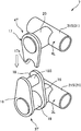
- FIG. 3 is a perspective view of the connecting device 1 of the connecting device shown in FIG.
- the connecting device 1 is provided on the side of the facing portion T (FIG. 2) when the front strut 3 and the rear strut 4 are laid down and stacked vertically (connected posture).
- the connecting device 1 of the present embodiment includes a first connected portion 3S, a second connected portion 4S, and a connecting pin 15.
- the first connected portion 3S extends outward from a first side surface 3L (FIGS. 2 and 3) extending along the longitudinal direction of the front strut 3.
- the first connected part 3S includes a first connecting support part 11 having a circular cross section and a predetermined length, and two connecting first plates 13.
- the two connecting first plates 13 constitute the first protrusion of the present invention.
- the second connected portion 4S extends outward from a second side surface 4L (FIGS. 2 and 3) extending along the longitudinal direction of the rear strut 4. Further, the second connected portion 4S is disposed to face the first connected portion 3S in the connecting posture of the front strut 3 and the rear strut 4 (FIGS. 1 to 3).
- the second coupled portion 4S includes a coupling second support portion 12 having a circular cross section and a predetermined length, and one coupling second plate 14.
- the connecting second plate 14 constitutes a second protrusion of the present invention.
- the connecting pin 15 functions as a connecting member that connects and connects the two connecting first plates 13 and the connecting second plate 14 from the side.
- the first connected portion 3S, the second connected portion 4S, and the connecting pin 15 constitute the connecting device 1 that connects the front strut 3 and the rear strut 4.
- the first connecting portion 11 for connection is outward from the side surface of the pipe member 21S (FIGS. 2 and 3) on the side close to the rear strut 4 of the pipe members 21 constituting the front strut 3 when stacked. It is provided in the side surface of the said pipe member 21S so that it may extend toward.
- the second support portion 12 for connection is outward from the side surface of the pipe member 31S (FIGS. 2 and 3) on the side close to the front strut 3 of the pipe members 31 constituting the rear strut 4 when stacked. It is provided in the side surface of the said pipe member 31S so that it may extend toward.
- the two connecting first plates 13 are protruded upward from the connecting first support portion 11 by being externally fixed to the connecting first support portion 11 with a gap therebetween. At this time, as shown in FIG. 2, the two connecting first plates 13 are arranged to extend upward from the front strut 3.
- the second connecting plate 14 is protruded downward from the second connecting support portion 12 by being externally fixed to the second connecting support portion 12. At this time, as shown in FIG. 2, one connecting second plate 14 is arranged to extend downward from the rear strut 4. Further, as shown in FIG. 3, the connecting second plate 14 has a width direction of the rear strut 4 that intersects the vertical direction and the longitudinal direction of the rear strut 4 (direction perpendicular to the paper surface of FIG. 1, right and left of FIG. 2).
- the upper and lower directions are directions when the rear strut 4 is stacked on the front strut 3 laid sideways.
- the second connecting plate 14 enters the gap between the two first connecting plates 13.
- a pin hole 13a and a pin hole 14a are formed in the first connecting plate 13 and the second connecting plate 14, respectively (see FIG. 3).
- the pin hole 13a and the pin hole 14a are opened so as to penetrate the first connecting plate 13 and the second connecting plate 14 along the width direction, respectively.
- the pin hole 13a and the pin hole 14a constitute a first hole part and a second hole part of the present invention, respectively.
- the connecting pin 15 (FIG.
- FIG. 4 is a perspective view of the alignment portion 7 of the coupling device shown in FIG.
- the alignment portion 7 regulates the relative position of the rear strut 4 with respect to the front strut 3 so that the pin hole 14a faces the pin hole 13a in the width direction in the connection posture.
- the alignment part 7 is provided on the side of the facing part T (FIG. 2) when the front strut 3 and the rear strut 4 are laid down side by side and stacked up and down in the same manner as the connecting device 1 described above.
- the alignment unit 7 includes a first alignment member 3T and a second alignment member 4T.
- the first alignment member 3T is disposed on the first side surface 3L of the front strut 3 (FIG. 4).
- the first alignment member 3T is fixed between the first alignment support portion 19 having a circular cross section and a predetermined length, the two alignment plates 16, and the two alignment plates 16.
- the second alignment member 4T is disposed on the second side surface 4L of the rear strut 4 (FIG. 4).
- the second alignment member 4T includes an alignment second support portion 20 having a circular cross section and a predetermined length, and one engagement plate 17.
- the alignment unit 7 is an instrument for aligning the positions of the pin holes 13 a of the first connecting plate 13 and the pin holes 14 a of the second connecting plate 14.
- the first support portion 19 for alignment extends outward from the side surface of the pipe member 21 ⁇ / b> S on the side close to the rear strut 4 of the pipe members 21 constituting the front strut 3 when stacked.
- the second support portion 20 for alignment extends outward from the side surface of the pipe member 31S on the side close to the front strut 3 of the pipe members 31 constituting the rear strut 4 when stacked. Is provided on the side surface of the pipe member 31S.
- the two alignment plates 16 are protruded upward from the alignment first support portion 19 by being externally fixed to the alignment first support portion 19 with a gap therebetween.
- the engagement plate 17 is protruded downward from the second alignment support portion 20 by being externally fixed to the second alignment support portion 20. Further, when the rear strut 4 is stacked on the front strut 3, the engagement plate 17 enters the gap between the two alignment plates 16.
- the positioning guide 18 has a cylindrical shape extending along the width direction of the front strut 3. Further, an arcuate recess 17 a is provided at the end of the engagement plate 17.
- the recessed portion 17a is formed so as to face the outer peripheral surface 18S of the positioning guide 18 in the up-down direction when the front strut 3 and the rear strut 4 are connected.
- the inner peripheral surface of the recess 17a and the outer peripheral surface 18S of the positioning guide 18 have the same diameter so as to come into surface contact with each other.
- the concave portion 17 a of the engagement plate 17 is placed on the positioning guide 18. That is, the concave portion 17a of the engagement plate 17 and the outer peripheral surface 18S of the positioning guide 18 are engaged with each other.
- the rear strut 4 is placed on the front strut 3 (a state in which the rear strut 4 is placed), and the relative position of the rear strut 4 with respect to the front strut 3 is restricted in the longitudinal direction and the vertical direction of the front strut 3.
- the holes of the pin hole 13a and the pin hole 14a are combined, and the two holes are in agreement with each other when viewed from the side.
- each component of the alignment portion 7 is arranged on the side surface of each strut so that the pin hole 13a and the pin hole 14a have such a positional relationship.
- the outer peripheral surface 18S of the positioning guide 18 and the recess 17a of the engagement plate 17 are brought into contact with each other by the weight of the rear strut 4 so that the relative positions of the pin hole 13a and the pin hole 14a in the vertical direction. To regulate.
- FIG. 5 is a side view showing a state in which a plurality of struts stacked vertically are connected by the connecting device according to the second embodiment of the present invention.
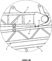
- FIG. 6 is an enlarged view of a portion B in FIG. In the description of the second embodiment, the same parts and members as those described in the first embodiment shown in FIG.
- the upper boom 5 shown in FIG. 5 constitutes the upper end portion of the boom of a luffing jib crane (not shown).
- the lower jib 2, the front strut 3, and the rear strut 4 respectively connected to the upper boom 5 via pins 2A, 3A, and 4A are transported together by a single trailer 50.
- the connecting device shown in the present embodiment is an upper surface of the front strut 3 with a predetermined interval between a pair of connecting devices 1 provided on the side surfaces of both ends in the width direction of the strut and the connecting device 1 in the longitudinal direction of the strut. And a set of receiving plates 6 fixed to the base plate.
- the receiving plate 6 constitutes a receiving part of the present invention.
- the receiving plate 6 is fixed to the upper surface of the pipe member 21 on the side close to the rear strut 4 when stacked, out of the pipe members 21 constituting the front strut 3.
- the receiving plate 6 is also disposed at a corresponding position on the back side of the drawing in FIGS.
- the receiving plate 6 When the rear strut 4 pinned to the upper boom 5 is tilted with the pinned portion (pin 4A) as a fulcrum, the receiving plate 6 has the tip of the rear strut 4 positioned above the front strut 3.
- the pipe member 21 is fixed in advance to the upper surface of the pipe member 21 at a location where it hits the pipe member 21.
- the tip end portion of the rear strut 4 abuts against the receiving plate 6 from above, so that the pipe member 21 constituting the front strut 3 is prevented from being damaged.
- the front strut 3 and the rear strut 4 are connected by a pin 4A via an upper boom 5 and are also connected by a connecting device 1 as shown in FIG. That is, since the front strut 3 and the rear strut 4 are connected to each other at two locations in the longitudinal direction of each strut, the rear strut 4 is sufficiently prevented from collapsing from the front strut 3 during transportation.
- the second connecting plate 14 is inserted into the gap between the two first connecting plates 13, but one connecting first plate 13 is provided.
- the connection first plate 13 and the connection second plate 14 may be connected by the connection pin 15.
- bolts and nuts may be used in place of the connection pins 15 described above, and the first plate for connection 13 and the second plate for connection 14 may be connected and fixed with bolts and nuts.
- a positioning guide 18 is disposed on the side of the front strut 3 and an engagement plate 17 is disposed on the side of the rear strut 4. 17 may be disposed, and a positioning guide 18 may be disposed on the side of the rear strut 4.
- Only one alignment plate 16 may be provided.
- the engagement plate 17 is set so as to extend longer than that shown in FIG. 4, the inner diameter of the recess 17 a is set in accordance with the outer diameter of the alignment first support portion 19, and the positioning guide 18. May be omitted. In this manner, the recess 17a of the engagement plate 17 may be engaged with the outer peripheral surface of the columnar first alignment support 19.
- the first alignment portion 19 for alignment is a member provided with the outer peripheral surface of the first alignment member 3T with which the concave portion 17a of the engagement plate 17 is engaged.
- the receiving plate 6 may be omitted. However, if the receiving plate 6 exists, when the rear strut 4 falls on the front strut 3, the front end portion of the rear strut 4 can be received by the receiving plate 6. Thereby, it is preferable that the front strut 3 is prevented from being damaged.
- the strut (attachment) to be connected may be not a lattice structure but a box structure (a cross section is composed of four plates). Note that the lattice structure is lighter, has higher rigidity, and higher strength than the box structure.
- the coupling device of the coupling device is provided on the side surface of the long attachment (for example, strut).
- the height of the connecting device hardly affects the height dimension when a plurality of long attachments constituting a work machine (for example, a crane) are stacked and fixed to each other. That is, according to this invention, the height dimension when attaching attachments up and down and mutually fixing can be reduced compared with the past. Thereby, the transport height at the time of transporting an attachment piled up and down can be restrained lower than before. Thereby, in a large crane, since more attachments can be transported collectively (or collectively transported), the number of trailers can be reduced, and transportation cost is reduced.
- the frame size of the attachment (for example, struts) can be ensured in a range that does not exceed the transport limit height.
- the first connecting plate 13 projecting upward from the first connecting support portion 11 and the second connecting plate projecting downward from the second connecting support portion 12 are provided.
- the first support portion 11 for connection and the second connection member are connected to each other by the two plates 14, the connection rod-like member (for example, the connection pin 15) that connects the first connection plate 13 and the second connection plate 14 from the side.
- a pin hole 13a (first hole) that is provided on a side surface of the attachment and into which a connection pin 15 (connection member) formed on the first plate for connection 13 is inserted; It is preferable to provide an alignment portion 7 for aligning with a pin hole 14a (second hole portion) into which the connection pin 15 (connection member) formed in the second connection plate 14 is inserted. According to this configuration, the pin holes (first hole portion, second hole portion) can be easily aligned.
- the above-described alignment unit 7 includes a first alignment member (for example, the positioning guide 18) disposed on one side of the stacked attachments and a first alignment disposed on the other side. It is preferable to include a second alignment member (for example, the engagement plate 17) having a recess that engages with the member. According to this configuration, the alignment unit 7 can be configured with a simple configuration.
- the connecting support portions 11 and 12 of the connecting device 1 and the alignment support portions 19 and 20 of the alignment portion 7 have the same shape and dimensions. Further, the connecting plates 13 and 14 of the connecting device 1 and the alignment plate 16 and the engagement plate 17 of the alignment unit 7 are similar in shape. Since the parts are shared in this way, the cost can be reduced.
- a plurality of connecting devices 1 it is preferable to arrange a plurality of connecting devices 1 at a predetermined interval in the longitudinal direction of the attachment.
- the receiving plate 6 with which the longitudinal end portion of the second attachment, which is the upper attachment, abuts from above is disposed at a predetermined distance from the connecting device 1 in the longitudinal direction of the attachment. It is preferable to open and fix to the upper surface of the first attachment which is the lower attachment. According to this configuration, it is possible to prevent the attachment from being damaged by contact between the attachments.
Landscapes
- Engineering & Computer Science (AREA)
- Mechanical Engineering (AREA)
- Transportation (AREA)
- Structural Engineering (AREA)
- General Engineering & Computer Science (AREA)
- Jib Cranes (AREA)
Abstract
連結装置は、作業機械を構成する第1アタッチメント(フロントストラット3)と第2アタッチメント(リヤストラット4)とを相互に連結する。連結装置は、第1被連結部3Sと、第2被連結部4Sと、連結部材(連結ピン15)と、を備える。第1被連結部3Sは、第1アタッチメントの長手方向に沿って延びる第1側面3Lから外方へ向かって延在する。第2被連結部4Sは、第2アタッチメントの長手方向に沿って延びる第2側面4Lから外方へ向かって延在し、第1アタッチメントおよび第2アタッチメントの連結姿勢において、第1被連結部3Sと相互に対向して配置される。連結部材は、第1被連結部3Sと第2被連結部4Sとを連結する。
Description
本発明は、クローラクレーンなどの作業機械を構成するストラットなどの複数の長尺のアタッチメントを上下に積み重ねるときに用いる連結装置に関する。
クローラクレーンなどの作業機械が分解され保管される際、または分解され輸送される際、ブーム、ストラットなどの複数の長尺のアタッチメントは上下に積み重ねられて崩れないように固定される。
この種の技術として、例えば下記の特許文献1、2に記載されたものがある。特許文献1では、上下に積み重ねられる前マストと後マストとの対向部にそれぞれフォークエンド、アイエンドと称される連結具が固定され、これら連結具同士がピンで連結される。特許文献2では、上下に積み重ねられる中間ブームの対向部にそれぞれラグが固定され、これらラグ同士が連結ピンで連結される。
クローラクレーンなどの作業機械が分解され例えばトレーラーに載せられて輸送される際、輸送制限高さが守られなければならない。大型の作業機械の場合、各アタッチメントも大型化するので、輸送制限高さを守るようにトレーラーへの積載を計画すると、アタッチメントを積み重ねて積載することが難しいことがある。この場合、各アタッチメントが単独で輸送される計画や、各アタッチメントがさらに分割され輸送される計画としなければならない。これは輸送コストの増大を招く。
ここで、上記した従来技術には次の問題がある。特許文献1、2に記載のアタッチメント同士の固定方法は、いずれも、上下に積み重ねられるアタッチメントの対向部にラグなどの連結具を固定してピン止めするというものであるので、当該連結具の高さ分、輸送高さが高くなってしまう。
本発明は、上記実情に鑑みてなされたものであり、その目的は、作業機械を構成する複数の長尺のアタッチメントを上下に積み重ねて相互に固定したときの高さ寸法を従来よりも低減することができるアタッチメントの連結装置を提供することである。
本発明に係る連結装置は、作業機械を構成する第1アタッチメントと第2アタッチメントとを相互に連結する。連結装置は、第1被連結部と、第2被連結部と、連結部材と、を備える。第1被連結部は、第1アタッチメントの長手方向に沿って延びる第1側面から外方へ向かって延在する。第2被連結部は、第2アタッチメントの長手方向に沿って延びる第2側面から外方へ向かって延在し、第2アタッチメントが第1アタッチメントの上に積み重ねられた第1アタッチメントおよび第2アタッチメントの連結姿勢において、第1被連結部と相互に対向して配置される。連結部材は、第1被連結部と第2被連結部とを連結する。
本発明によれば、アタッチメントの側面に連結装置の第1被連結部および第2被連結部が設けられているので、連結装置の高さは、作業機械を構成する複数の長尺のアタッチメントを上下に積み重ねて相互に固定したときの高さ寸法にほとんど影響を与えない。すなわち、アタッチメントを上下に積み重ねて相互に固定したときの高さ寸法が従来よりも低減される。
以下、本発明を実施するための形態について図面を参照しつつ説明する。なお、以下に示す実施形態では、作業機械である不図示のラッフィングジブクレーン(ブームの先端部にジブが取り付けられたクレーン)が分解され、輸送される際の例を示している。その他の様々な形式のクレーンが、分解後に、輸送または保管されるときに、クレーンを構成する長尺のアタッチメントに設けた本発明の連結装置を用いることができる。上記長尺のアタッチメントとしては、ストラット、ジブ、ブーム、マストなどを挙げることができる。
(第1実施形態)
図1は、本発明の第1実施形態に係る連結装置によって、上下に積み重ねられた複数のストラットが連結された状態を示す側面図である。ラッフィングジブクレーンを構成する長尺のアタッチメントは、分解され、例えば図1に示す形態でトレーラー50に積載されて輸送される。図1に示す下部ジブ2は、ラッフィングジブクレーンの不図示のブームの先端部に取り付けられるジブの下部部分を構成する。また、図1に示されるフロントストラット3は本発明の第1アタッチメントを構成し、リヤストラット4は本発明の第2アタッチメントを構成する。フロントストラット3およびリヤストラット4は、それぞれ、ラッフィングジブクレーンのジブの先端に回動可能に装着される。図1では、下部ジブ2にピン3Aを介して取り付けられたフロントストラット3が下部ジブ2の上で折り畳まれ、そのフロントストラット3の上にリヤストラット4が積み重ねられて、下部ジブ2、フロントストラット3、およびリヤストラット4が1台のトレーラー50で一緒に輸送される。なお、図1に示すように、リヤストラット4がフロントストラット3の上に積み重ねられた姿勢が、フロントストラット3およびリヤストラット4の連結姿勢と定義される。
図1は、本発明の第1実施形態に係る連結装置によって、上下に積み重ねられた複数のストラットが連結された状態を示す側面図である。ラッフィングジブクレーンを構成する長尺のアタッチメントは、分解され、例えば図1に示す形態でトレーラー50に積載されて輸送される。図1に示す下部ジブ2は、ラッフィングジブクレーンの不図示のブームの先端部に取り付けられるジブの下部部分を構成する。また、図1に示されるフロントストラット3は本発明の第1アタッチメントを構成し、リヤストラット4は本発明の第2アタッチメントを構成する。フロントストラット3およびリヤストラット4は、それぞれ、ラッフィングジブクレーンのジブの先端に回動可能に装着される。図1では、下部ジブ2にピン3Aを介して取り付けられたフロントストラット3が下部ジブ2の上で折り畳まれ、そのフロントストラット3の上にリヤストラット4が積み重ねられて、下部ジブ2、フロントストラット3、およびリヤストラット4が1台のトレーラー50で一緒に輸送される。なお、図1に示すように、リヤストラット4がフロントストラット3の上に積み重ねられた姿勢が、フロントストラット3およびリヤストラット4の連結姿勢と定義される。
本発明に係る連結装置は、連結器具1を備える。フロントストラット3とリヤストラット4とは連結器具1で相互に連結される。連結器具1は、ストラットの長手方向において所定の間隔をあけて複数配置されることが望ましく、本実施形態では、ストラットの長手方向両端部の側面にそれぞれ配置されている。なお、図1の紙面奥側に対応する位置にも連結器具1が配置されており(図2参照)、本実施形態ではこれら計4つの連結器具1が配置されている。
また、フロントストラット3の上にリヤストラット4が重ねられるときの、長手方向におけるフロントストラット3およびリヤストラット4の相互の位置合わせは位置合わせ部7を利用して行われる。位置合わせ部7は、ストラットの側面であってそれぞれの連結器具1の近くに(連結器具1との間に所定の間隔をあけて)配置されている。上記連結器具1と同様に、位置合わせ部7は、ストラットの幅方向両側に配置されており、すなわち、本実施形態では計4つの位置合わせ部7が配置されている。本実施形態では、計4つの連結器具1と計4つの位置合わせ部7とで連結装置が構成されている。
図2は、図1のA-A断面図であって、後記の連結ピン15が装着されていない状態の図である。フロントストラット3は、ラチス構造のストラットであり、図2に示すように、長手方向に延びる4本のパイプ部材21と、パイプ部材21を連結する複数の連結部材22とを有する。同様に、リヤストラット4もラチス構造のストラットであり、図2に示すように、長手方向に延びる4本のパイプ部材31と、パイプ部材31を連結する複数の連結部材32とをリヤストラット4は有する。
図3は、図1に示す連結装置の連結器具1の斜視図である。連結器具1は、フロントストラット3とリヤストラット4とが横に寝かされて上下に積み重ねられたとき(連結姿勢)の対向部T(図2)の側方に設けられる。本実施形態のこの連結器具1は、第1被連結部3Sと、第2被連結部4Sと、連結ピン15と、を備える。第1被連結部3Sは、フロントストラット3の長手方向に沿って延びる第1側面3L(図2、図3)から外方へ向かって延在する。第1被連結部3Sは、断面円形で所定長さを有する連結用第1支持部11と、2枚の連結用第1プレート13と、を備える。2枚の連結用第1プレート13は、本発明の第1突出部を構成する。第2被連結部4Sは、リヤストラット4の長手方向に沿って延びる第2側面4L(図2、図3)から外方へ向かって延在する。また、第2被連結部4Sは、フロントストラット3およびリヤストラット4の連結姿勢(図1乃至図3)において、第1被連結部3Sと相互に対向して配置される。第2被連結部4Sは、断面円形で所定長さを有する連結用第2支持部12と、1枚の連結用第2プレート14と、を備える。連結用第2プレート14は、本発明の第2突出部を構成する。連結ピン15は、2枚の連結用第1プレート13および1枚の連結用第2プレート14をその側方からピン止めして連結する連結部材として機能する。第1被連結部3S、第2被連結部4Sおよび連結ピン15で、フロントストラット3とリヤストラット4とを連結する連結器具1が構成される。
連結用第1支持部11は、フロントストラット3を構成するパイプ部材21のうちの、積み重ねられたときのリヤストラット4に近い側のパイプ部材21S(図2、図3)の側面から外方へ向かって延在するように当該パイプ部材21Sの側面に設けられる。連結用第2支持部12は、リヤストラット4を構成するパイプ部材31のうちの、積み重ねられたときのフロントストラット3に近い側のパイプ部材31S(図2、図3)の側面から外方へ向かって延在するように当該パイプ部材31Sの側面に設けられる。
2枚の連結用第1プレート13は、間隔をあけて連結用第1支持部11に外挿固定されることで当該連結用第1支持部11から上方へ向かって突設される。この際、図2に示すように、2枚の連結用第1プレート13は、フロントストラット3よりも上方に延びるように配置される。連結用第2プレート14は、連結用第2支持部12に外挿固定されることで当該連結用第2支持部12から下方へ向かって突設される。この際、図2に示すように、1枚の連結用第2プレート14は、リヤストラット4よりも下方に延びるように配置される。また、図3に示すように、連結用第2プレート14は、上下方向とリヤストラット4の長手方向とそれぞれ交差するリヤストラット4の幅方向(図1の紙面と直交する方向、図2の左右方向)において連結用第1プレート13に対向して配置される。なお、上方、下方とは、横に寝かされたフロントストラット3の上にリヤストラット4が積み重ねられたときの方向のことである。また、フロントストラット3の上にリヤストラット4が積み重ねられたときに、2枚の連結用第1プレート13の間の隙間に連結用第2プレート14が入り込む。連結用第1プレート13および連結用第2プレート14には、それぞれ、ピン孔13aおよびピン孔14aが形成されている(図3参照)。ピン孔13aおよびピン孔14aは、それぞれ、連結用第1プレート13および連結用第2プレート14を上記の幅方向に沿って貫通するように開口されている。また、ピン孔13aおよびピン孔14aは、それぞれ、本発明の第1孔部および第2孔部を構成する。また、連結ピン15(図3)は、前記幅方向においてピン孔13aおよびピン孔14aを跨ぐ長さ(一対のピン孔13aを跨ぐ長さ)を備えている。連結ピン15は、前記幅方向に沿ってピン孔13aおよびピン孔14aに嵌め込まれることで(図3の一点鎖線参照)、連結用第1プレート13と連結用第2プレート14とを前記幅方向に沿って連結する。
図4は、図1に示す連結装置の位置合わせ部7の斜視図である。位置合わせ部7は、前記連結姿勢において、ピン孔14aが前記幅方向においてピン孔13aに対向するように、フロントストラット3に対するリヤストラット4の相対位置を規制する。位置合わせ部7は、前記した連結器具1と同様に、フロントストラット3とリヤストラット4とが横に寝かされて上下に積み重ねられたときの対向部T(図2)の側方に設けられる。図4に示したように、位置合わせ部7は、第1位置合わせ部材3Tと、第2位置合わせ部材4Tと、を備える。第1位置合わせ部材3Tは、フロントストラット3の第1側面3Lに配置される(図4)。第1位置合わせ部材3Tは、断面円形で所定長さを有する位置合せ用第1支持部19と、2枚の位置合せ用プレート16と、2枚の位置合せ用プレート16の間に固定される位置決めガイド18と、を備える。一方、第2位置合わせ部材4Tは、リヤストラット4の第2側面4Lに配置される(図4)。第2位置合わせ部材4Tは、断面円形で所定長さを有する位置合せ用第2支持部20と、1枚の係合プレート17と、を備える。前述のように、位置合わせ部7は、連結用第1プレート13のピン孔13aと連結用第2プレート14のピン孔14aとの位置を合わせるための器具である。
位置合せ用第1支持部19は、フロントストラット3を構成するパイプ部材21のうちの、積み重ねられたときのリヤストラット4に近い側のパイプ部材21Sの側面から外方へ向かって延在するように当該パイプ部材21Sの側面に設けられる。位置合せ用第2支持部20は、リヤストラット4を構成するパイプ部材31のうちの、積み重ねられたときのフロントストラット3に近い側のパイプ部材31Sの側面から外方へ向かって延在するように当該パイプ部材31Sの側面に設けられる。
2枚の位置合せ用プレート16は、間隔をあけて位置合せ用第1支持部19に外挿固定されることで当該位置合せ用第1支持部19から上方へ向かって突設される。係合プレート17は、位置合せ用第2支持部20に外挿固定されることで当該位置合せ用第2支持部20から下方へ向かって突設される。また、フロントストラット3の上にリヤストラット4が積み重ねられたときに、2枚の位置合せ用プレート16の間の隙間に係合プレート17が入り込む。位置決めガイド18は、フロントストラット3の幅方向に沿って延びる円柱形状からなる。また、係合プレート17の端部には円弧状の凹部17aが設けられている。凹部17aは、フロントストラット3およびリヤストラット4の連結姿勢において、位置決めガイド18の外周面18Sに上下方向において対向するように形成されている。この凹部17aの内周面と上記位置決めガイド18の外周面18Sとは相互に面接触するように同径とされている。
フロントストラット3の上にリヤストラット4が積み重ねられる際、係合プレート17の凹部17aを位置決めガイド18の上にのせる。すなわち、係合プレート17の凹部17aと位置決めガイド18の外周面18Sとが互いに係合する。これにより、フロントストラット3の上にリヤストラット4がのった状態(あずけられた状態)となるとともに、フロントストラット3の長手方向および上下方向においてフロントストラット3に対するリヤストラット4の相対位置が規制される。この結果、上記ピン孔13aおよびピン孔14aの孔が合わさり、側方から視て両者の孔が一致した状態となる。フロントストラット3およびリヤストラット4の連結姿勢において、ピン孔13aおよびピン孔14aがこのような位置関係になるように、各ストラットの側面に位置合わせ部7の各部品が配置されている。なお、上記の連結姿勢において、位置決めガイド18の外周面18Sおよび係合プレート17の凹部17aは、リヤストラット4の自重によって互いに当接することで、上下方向においてピン孔13aおよびピン孔14aの相対位置を規制する。そして、作業者によってピン孔13aおよびピン孔14aに連結ピン15が打ち込まれると、上下に積み重ねられたフロントストラット3とリヤストラット4とが連結され、輸送の際にリヤストラット4がフロントストラット3から崩れ落ちることが防止される。
(第2実施形態)
図5は、本発明の第2実施形態に係る連結装置によって、上下に積み重ねられた複数のストラットが連結された状態を示す側面図である。図6は、図5のB部拡大図である。この第2実施形態の説明では、図1等に示す第1実施形態で説明した部品、部材と同じ部品、部材には同一の符号を付している。
図5は、本発明の第2実施形態に係る連結装置によって、上下に積み重ねられた複数のストラットが連結された状態を示す側面図である。図6は、図5のB部拡大図である。この第2実施形態の説明では、図1等に示す第1実施形態で説明した部品、部材と同じ部品、部材には同一の符号を付している。
図5に示す上部ブーム5は、不図示のラッフィングジブクレーンのブームの上端部分を構成するものである。本実施形態では、それぞれ上部ブーム5にピン2A、3A、4Aを介して連結された、下部ジブ2、フロントストラット3、およびリヤストラット4が1台のトレーラー50でまとめて輸送される。
本実施形態で示す連結装置は、ストラットの幅方向両端部側面に設けられる1組の連結器具1と、ストラットの長手方向において連結器具1との間に所定の間隔をあけてフロントストラット3の上面に固定される1組の受け板6とで構成される。受け板6は、本発明の受け部を構成する。
受け板6は、フロントストラット3を構成するパイプ部材21のうちの、積み重ねられたときのリヤストラット4に近い側のパイプ部材21の上面に固定される。なお、受け板6は、図5および図6の紙面奥側の対応する位置にも配置される。
この受け板6は、上部ブーム5にピン止めされたリヤストラット4が、そのピン止め部分(ピン4A)を支点にして倒されてきたときに、リヤストラット4の先端部がフロントストラット3の上記パイプ部材21に当たる箇所のパイプ部材21の上面に予め固定されている。これにより、リヤストラット4が折り畳まれ連結姿勢とされると、リヤストラット4の先端部が上方から受け板6に当接するので、フロントストラット3を構成するパイプ部材21が傷つくことが防止される。なお、フロントストラット3とリヤストラット4とは、上部ブーム5を介してピン4Aで連結されているとともに、図3に示されるような連結器具1によっても連結される。すなわち、各ストラットの長手方向の2箇所でフロントストラット3およびリヤストラット4が相互に連結されるので、輸送の際にリヤストラット4がフロントストラット3から崩れ落ちることが十分に防止される。
(変形例)
図3等に示したように、上記した実施形態では、2枚の連結用第1プレート13の間の隙間に連結用第2プレート14が挿入されるが、連結用第1プレート13が1枚のみからなり、連結用第1プレート13と連結用第2プレート14とが連結ピン15によって連結されてもよい。
図3等に示したように、上記した実施形態では、2枚の連結用第1プレート13の間の隙間に連結用第2プレート14が挿入されるが、連結用第1プレート13が1枚のみからなり、連結用第1プレート13と連結用第2プレート14とが連結ピン15によって連結されてもよい。
前記した連結ピン15に代えて、例えばボルト・ナットが用いられ、連結用第1プレート13と連結用第2プレート14とがボルト・ナットで連結固定されてもよい。
位置合わせ部7を連結器具1の近くに配置する必要は必ずしもない。
位置合わせ部7に関し、フロントストラット3の側方に位置決めガイド18が配置され、リヤストラット4の側方に係合プレート17が配置されることに代えて、フロントストラット3の側方に係合プレート17が配置され、リヤストラット4の側方に位置決めガイド18が配置されてもよい。
位置合せ用プレート16は1枚のみであってもよい。
係合プレート17が図4に示したものよりも下方に長く延びるように設定されるとともに、位置合せ用第1支持部19の外径にあわせて凹部17aの内径が設定され、且つ位置決めガイド18が省略されてもよい。このようにして、係合プレート17の凹部17aが円柱状の位置合せ用第1支持部19の外周面に係合する態様でもよい。この場合、位置合せ用第1支持部19は、係合プレート17の凹部17aが係合する、第1位置合わせ部材3Tの外周面を備える部材となる。
図5,図6に示した第2実施形態に関し、受け板6が省略されてもよい。ただし、受け板6が存在すれば、フロントストラット3の上にリヤストラット4が倒れていったときに、リヤストラット4の先端部を受け板6で受けることができる。これにより、フロントストラット3が傷つくことが防止され好ましい。
連結対象のストラット(アタッチメント)は、ラチス構造でなく箱構造(断面が4枚の板で構成されたもの)であってもよい。なお、箱構造よりもラチス構造の方が軽量で高剛性、高強度を得られる。
(作用・効果)
本発明によれば、長尺のアタッチメント(例えばストラット)の側面に連結装置の連結器具が設けられている。連結器具の高さは、作業機械(例えばクレーン)を構成する複数の長尺のアタッチメントを上下に積み重ねて相互に固定したときの高さ寸法にほとんど影響を与えない。すなわち、本発明によれば、アタッチメントを上下に積み重ねて相互に固定したときの高さ寸法を従来よりも低減することができる。これにより、アタッチメントを上下に積み重ねて輸送する際の輸送高さを従来よりも低く抑えることができる。これにより、大型のクレーンにおいては、より多くのアタッチメントをまとめて輸送(または、まとめて一体輸送)できるので、トレーラーの台数を減ずることができ、輸送コストが低減する。また、別の観点からは、輸送高さを従来よりも低く抑えることができるので、輸送制限高さを超えない範囲で、アタッチメント(例えばストラット)の枠寸を大きく確保することができ、従来よりも高剛性、高強度のアタッチメントとすることができる。
本発明によれば、長尺のアタッチメント(例えばストラット)の側面に連結装置の連結器具が設けられている。連結器具の高さは、作業機械(例えばクレーン)を構成する複数の長尺のアタッチメントを上下に積み重ねて相互に固定したときの高さ寸法にほとんど影響を与えない。すなわち、本発明によれば、アタッチメントを上下に積み重ねて相互に固定したときの高さ寸法を従来よりも低減することができる。これにより、アタッチメントを上下に積み重ねて輸送する際の輸送高さを従来よりも低く抑えることができる。これにより、大型のクレーンにおいては、より多くのアタッチメントをまとめて輸送(または、まとめて一体輸送)できるので、トレーラーの台数を減ずることができ、輸送コストが低減する。また、別の観点からは、輸送高さを従来よりも低く抑えることができるので、輸送制限高さを超えない範囲で、アタッチメント(例えばストラット)の枠寸を大きく確保することができ、従来よりも高剛性、高強度のアタッチメントとすることができる。
また、本発明においては、連結用第1支持部11から上方へ向かって突設された連結用第1プレート13と、連結用第2支持部12から下方へ向かって突設された連結用第2プレート14と、連結用第1プレート13と連結用第2プレート14とを側方から連結する連結用棒状部材(例えば連結ピン15)とで、連結用第1支持部11と連結用第2支持部12とを連結する連結部材を構成することが好ましい。この構成によると、上下に積み重ねられたアタッチメントの高さを低減できるとともに、アタッチメント同士の接触をより確実に防止することができる。
また、第1実施形態で示したように、アタッチメントの側面に設けられ、連結用第1プレート13に形成された連結ピン15(連結部材)が入れられるピン孔13a(第1孔部)と、連結用第2プレート14に形成された連結ピン15(連結部材)が入れられるピン孔14a(第2孔部)との位置を合わせるための位置合わせ部7を設けることが好ましい。この構成によると、ピン孔(第1孔部、第2孔部)の位置合わせが容易となる。
また、上記した位置合わせ部7は、積み重ねるアタッチメントのうちの一方の側方に配置された第1位置合わせ部材(例えば、位置決めガイド18)と、他方の側方に配置された、第1位置合わせ部材に係合する凹部を有する第2位置合わせ部材(例えば、係合プレート17)とを含んで構成されることが好ましい。この構成によると、簡易な構成で位置合わせ部7を構成することができる。
また、上記した実施形態では、連結器具1の連結用支持部11,12と、位置合わせ部7の位置合せ用支持部19,20とは、形状・寸法が同じである。且つ、連結器具1の連結用プレート13,14と、位置合わせ部7の位置合せ用プレート16・係合プレート17とは形状が類似する。このように部品の共通化が図られているので、コストを低減することができる。
また、第1実施形態で示したように、アタッチメントの長手方向において所定の間隔をあけて複数の連結器具1を配置することが好ましい。アタッチメントの長手方向における複数箇所でアタッチメントを連結することで、輸送時のアタッチメントの固定がより安定する。
また、第2実施形態で示したように、上側のアタッチメントである第2アタッチメントの長手方向端部が上方から当接する受け板6を、アタッチメントの長手方向において連結器具1との間に所定の間隔をあけて下側のアタッチメントである第1アタッチメントの上面に固定することが好ましい。この構成によると、アタッチメント同士の接触によりアタッチメントが傷つくことを防止することができる。
以上、本発明の実施形態およびその変形例について説明したが、その他に、当業者が想定できる範囲で種々の変更を行えることは勿論である。
Claims (9)
- 作業機械を構成する第1アタッチメントと第2アタッチメントとを相互に連結する連結装置であって、
前記第1アタッチメントの長手方向に沿って延びる第1側面から外方へ向かって延在する第1被連結部と、
第2アタッチメントの長手方向に沿って延びる第2側面から外方へ向かって延在し、前記第2アタッチメントが前記第1アタッチメントの上に積み重ねられた前記第1アタッチメントおよび前記第2アタッチメントの連結姿勢において、前記第1被連結部と相互に対向して配置される第2被連結部と、
前記第1被連結部と前記第2被連結部とを連結する連結部材と、
を備える、アタッチメントの連結装置。 - 請求項1に記載のアタッチメントの連結装置において、
前記第1被連結部は、前記連結姿勢において、前記第1アタッチメントよりも上方に延びる第1突出部を備え、
前記第2被連結部は、前記連結姿勢において、前記第2アタッチメントよりも下方に延びるとともに、上下方向と前記第2アタッチメントの長手方向とそれぞれ交差する前記第2アタッチメントの幅方向において前記第1突出部に対向して配置される第2突出部を備え、
前記連結部材は、前記第1突出部と前記第2突出部とを前記幅方向に沿って連結する、アタッチメントの連結装置。 - 請求項2に記載のアタッチメントの連結装置において、
前記第1突出部には、前記第1突出部を前記幅方向に沿って貫通する第1孔部が開口されており、
前記第2突出部には、前記第2突出部を前記幅方向に沿って貫通する第2孔部が開口されており、
前記連結部材は、前記幅方向において前記第1孔部および前記第2孔部を跨ぐ長さを備え、前記幅方向に沿って前記第1孔部および前記第2孔部に嵌め込まれることで前記第1突出部と前記第2突出部とを連結する、アタッチメントの連結装置。 - 請求項3に記載のアタッチメントの連結装置において、
前記連結姿勢において、前記第2孔部が前記幅方向において前記第1孔部に対向するように、前記第1アタッチメントに対する前記第2アタッチメントの相対位置を規制する位置合わせ部を更に備える、アタッチメントの連結装置。 - 請求項4に記載のアタッチメントの連結装置において、
前記位置合わせ部は、
前記第1アタッチメントの前記第1側面および前記第2アタッチメントの前記第2側面のうちの一方に配置された第1位置合わせ部材と、
前記第1アタッチメントの前記第1側面および前記第2アタッチメントの前記第2側面のうちの他方に配置され、前記第1位置合わせ部材に係合することで、前記第1アタッチメントに対する前記第2アタッチメントの相対位置を規制する第2位置合わせ部材と、
を備える、アタッチメントの連結装置。 - 請求項5に記載のアタッチメントの連結装置において、
前記第1位置合わせ部材は、前記幅方向に沿って延びる外周面を備え、
前記第2位置合わせ部材は、前記連結姿勢において前記第1位置合わせ部材の前記外周面に上下方向において対向するように形成された凹部を備え、
前記第1位置合わせ部材の前記外周面および前記第2位置合わせ部材の前記凹部は、前記連結姿勢において互いに係合することで、前記第1アタッチメントの長手方向および上下方向において前記第1アタッチメントに対する前記第2アタッチメントの相対位置を規制する、アタッチメントの連結装置。 - 請求項6に記載のアタッチメントの連結装置において、
前記連結姿勢において、前記第1位置合わせ部材の前記外周面および前記第2位置合わせ部材の前記凹部は、前記第2アタッチメントの自重によって互いに当接することで、上下方向において前記第1孔部に対する前記第2孔部の相対位置を規制する、アタッチメントの連結装置。 - 請求項1~7のいずれかに記載のアタッチメントの連結装置において、
前記第1被連結部、前記第2被連結部および前記連結部材は、前記第1アタッチメントおよび前記第2アタッチメントの長手方向において、所定の間隔をあけて複数配置されている、アタッチメントの連結装置。 - 請求項1~7のいずれかに記載のアタッチメントの連結装置において、
前記第1アタッチメントの長手方向において前記第1被連結部との間に所定の間隔をあけて前記第1アタッチメントの上面に固定され、前記連結姿勢において前記第2アタッチメントが上方から当接する受け部をさらに備える、アタッチメントの連結装置。
Priority Applications (3)
| Application Number | Priority Date | Filing Date | Title |
|---|---|---|---|
| SG11201800331SA SG11201800331SA (en) | 2015-07-16 | 2016-07-11 | Connecting device for attachments |
| EP16824421.8A EP3323768B1 (en) | 2015-07-16 | 2016-07-11 | Connecting device for attachments |
| US15/745,279 US10704579B2 (en) | 2015-07-16 | 2016-07-11 | Connecting device for attachments |
Applications Claiming Priority (2)
| Application Number | Priority Date | Filing Date | Title |
|---|---|---|---|
| JP2015141812A JP6160660B2 (ja) | 2015-07-16 | 2015-07-16 | アタッチメントの連結装置 |
| JP2015-141812 | 2015-07-16 |
Publications (1)
| Publication Number | Publication Date |
|---|---|
| WO2017010441A1 true WO2017010441A1 (ja) | 2017-01-19 |
Family
ID=57757467
Family Applications (1)
| Application Number | Title | Priority Date | Filing Date |
|---|---|---|---|
| PCT/JP2016/070371 Ceased WO2017010441A1 (ja) | 2015-07-16 | 2016-07-11 | アタッチメントの連結装置 |
Country Status (5)
| Country | Link |
|---|---|
| US (1) | US10704579B2 (ja) |
| EP (1) | EP3323768B1 (ja) |
| JP (1) | JP6160660B2 (ja) |
| SG (1) | SG11201800331SA (ja) |
| WO (1) | WO2017010441A1 (ja) |
Families Citing this family (3)
| Publication number | Priority date | Publication date | Assignee | Title |
|---|---|---|---|---|
| JP6805859B2 (ja) * | 2017-02-08 | 2020-12-23 | コベルコ建機株式会社 | ジブ係留装置の取付構造 |
| JP7358854B2 (ja) * | 2019-09-02 | 2023-10-11 | コベルコ建機株式会社 | 構造物保持装置 |
| JP7608773B2 (ja) | 2020-10-13 | 2025-01-07 | コベルコ建機株式会社 | ジブ固定装置 |
Citations (3)
| Publication number | Priority date | Publication date | Assignee | Title |
|---|---|---|---|---|
| JPS5830682U (ja) * | 1981-08-21 | 1983-02-28 | 日立建機株式会社 | 移動式タワ−クレ−ン |
| JPH11165986A (ja) * | 1997-12-02 | 1999-06-22 | Nippon Sharyo Seizo Kaisha Ltd | クレーンの中間ブーム |
| WO2010024151A1 (ja) * | 2008-08-29 | 2010-03-04 | 株式会社 タダノ | ジブ付きクレーン車のジブ格納装置 |
Family Cites Families (15)
| Publication number | Priority date | Publication date | Assignee | Title |
|---|---|---|---|---|
| US1941952A (en) * | 1931-12-26 | 1934-01-02 | Manitowoc Shipbuilding Corp | Boom construction |
| US2975910A (en) * | 1958-06-06 | 1961-03-21 | Clark Equipment Co | Crane boom |
| US3085695A (en) * | 1961-03-23 | 1963-04-16 | Carl A Miller | Hinge for crane boom |
| US3306470A (en) * | 1965-01-25 | 1967-02-28 | Robert A Green | Folding boom for mobile cranes |
| DE1297834B (de) * | 1967-03-11 | 1969-06-19 | E H Hans Dr Ing | Fahrbarer Mehrzweckkran |
| US3511388A (en) * | 1967-09-18 | 1970-05-12 | Manitowoc Co | Pin connection for elongate load supporting boom structure |
| US4016974A (en) * | 1974-11-08 | 1977-04-12 | Hans Tax | Package for transporting units of a modular crane |
| JPS61101593U (ja) | 1984-12-07 | 1986-06-28 | ||
| US5193698A (en) | 1990-09-13 | 1993-03-16 | Kabushiki Kaisha Kobe Seiko Sho | Jib stretching and folding device for use in a crane |
| US5199586A (en) * | 1991-07-25 | 1993-04-06 | The Manitowoc Company, Inc. | Quick-connect sectional boom members for cranes and the like |
| JPH1111877A (ja) | 1997-06-24 | 1999-01-19 | Tadano Ltd | 車両搭載クレーンのジブ格納装置 |
| JP2004018251A (ja) | 2002-06-20 | 2004-01-22 | Sumitomo Heavy Industries Construction Crane Co Ltd | クレーン用中間ブーム |
| JP2009149438A (ja) * | 2007-11-29 | 2009-07-09 | Manitowoc Crane Companies Ltd | クレーンブームセグメント用の接続システム |
| US8839966B2 (en) * | 2009-03-31 | 2014-09-23 | Manitowoc Crane Companies, Llc | Folding jib main strut and transportable reeved strut caps |
| US20140131300A1 (en) * | 2012-11-09 | 2014-05-15 | Gru Comedil S.R.L. | Jib for a crane |
-
2015
- 2015-07-16 JP JP2015141812A patent/JP6160660B2/ja active Active
-
2016
- 2016-07-11 EP EP16824421.8A patent/EP3323768B1/en active Active
- 2016-07-11 SG SG11201800331SA patent/SG11201800331SA/en unknown
- 2016-07-11 WO PCT/JP2016/070371 patent/WO2017010441A1/ja not_active Ceased
- 2016-07-11 US US15/745,279 patent/US10704579B2/en active Active
Patent Citations (3)
| Publication number | Priority date | Publication date | Assignee | Title |
|---|---|---|---|---|
| JPS5830682U (ja) * | 1981-08-21 | 1983-02-28 | 日立建機株式会社 | 移動式タワ−クレ−ン |
| JPH11165986A (ja) * | 1997-12-02 | 1999-06-22 | Nippon Sharyo Seizo Kaisha Ltd | クレーンの中間ブーム |
| WO2010024151A1 (ja) * | 2008-08-29 | 2010-03-04 | 株式会社 タダノ | ジブ付きクレーン車のジブ格納装置 |
Non-Patent Citations (1)
| Title |
|---|
| See also references of EP3323768A4 * |
Also Published As
| Publication number | Publication date |
|---|---|
| JP6160660B2 (ja) | 2017-07-12 |
| EP3323768A4 (en) | 2018-10-03 |
| US20190032690A1 (en) | 2019-01-31 |
| JP2017024813A (ja) | 2017-02-02 |
| EP3323768A1 (en) | 2018-05-23 |
| EP3323768B1 (en) | 2020-04-08 |
| US10704579B2 (en) | 2020-07-07 |
| SG11201800331SA (en) | 2018-02-27 |
Similar Documents
| Publication | Publication Date | Title |
|---|---|---|
| US9458606B2 (en) | Boom apparatus with protective barrier for flexible line | |
| WO2017010441A1 (ja) | アタッチメントの連結装置 | |
| JP2016108118A (ja) | カウンタウエイト装置および作業機械 | |
| EP3556717B1 (en) | Construction machine | |
| AU2019268668B2 (en) | Lattice structure, lattice structure coupling body, work machine, and connector | |
| US11142437B2 (en) | Rising and falling body of work machine and method for storing rising and falling body of work machine | |
| JP2008280166A (ja) | ジブ格納装置 | |
| CN106715316A (zh) | 起重机 | |
| CN204454344U (zh) | 一种臂架装置及工程机械 | |
| JP6540652B2 (ja) | 着脱機構 | |
| KR20150027989A (ko) | 크레인용 보조공구 | |
| JP7358854B2 (ja) | 構造物保持装置 | |
| JP6778415B2 (ja) | 移動式クレーン | |
| JP6837885B2 (ja) | ピン結合装置 | |
| US11787672B2 (en) | Lattice structure, lattice structure coupling body, work machine, and connector | |
| CN103407911A (zh) | 一种正面吊运起重机的起重装置及正面吊运起重机 | |
| JP2015147463A (ja) | クローラ式車両 | |
| JP7380686B2 (ja) | 伸縮ブーム及び作業機 | |
| EP4406907B1 (en) | Crane | |
| JP7435580B2 (ja) | コネクタ格納装置 | |
| JP7314673B2 (ja) | ブーム支持構造 | |
| JP2017039590A (ja) | 建設機械およびカーボディウエイトの取付方法 | |
| JP6562040B2 (ja) | 建設機械 | |
| CN107735351A (zh) | 伸缩起重臂的安装构造 | |
| KR101497550B1 (ko) | 구조물 인양용 러그 |
Legal Events
| Date | Code | Title | Description |
|---|---|---|---|
| 121 | Ep: the epo has been informed by wipo that ep was designated in this application |
Ref document number: 16824421 Country of ref document: EP Kind code of ref document: A1 |
|
| WWE | Wipo information: entry into national phase |
Ref document number: 11201800331S Country of ref document: SG |
|
| NENP | Non-entry into the national phase |
Ref country code: DE |
|
| WWE | Wipo information: entry into national phase |
Ref document number: 2016824421 Country of ref document: EP |