WO2017014092A1 - Appareil de formation de film d'enroulement permettant un dépôt de couche atomique et procédé de dépôt de couche atomique - Google Patents
Appareil de formation de film d'enroulement permettant un dépôt de couche atomique et procédé de dépôt de couche atomique Download PDFInfo
- Publication number
- WO2017014092A1 WO2017014092A1 PCT/JP2016/070445 JP2016070445W WO2017014092A1 WO 2017014092 A1 WO2017014092 A1 WO 2017014092A1 JP 2016070445 W JP2016070445 W JP 2016070445W WO 2017014092 A1 WO2017014092 A1 WO 2017014092A1
- Authority
- WO
- WIPO (PCT)
- Prior art keywords
- atomic layer
- film
- base material
- layer deposition
- zone
- Prior art date
- Legal status (The legal status is an assumption and is not a legal conclusion. Google has not performed a legal analysis and makes no representation as to the accuracy of the status listed.)
- Ceased
Links
Images




Classifications
-
- C—CHEMISTRY; METALLURGY
- C23—COATING METALLIC MATERIAL; COATING MATERIAL WITH METALLIC MATERIAL; CHEMICAL SURFACE TREATMENT; DIFFUSION TREATMENT OF METALLIC MATERIAL; COATING BY VACUUM EVAPORATION, BY SPUTTERING, BY ION IMPLANTATION OR BY CHEMICAL VAPOUR DEPOSITION, IN GENERAL; INHIBITING CORROSION OF METALLIC MATERIAL OR INCRUSTATION IN GENERAL
- C23C—COATING METALLIC MATERIAL; COATING MATERIAL WITH METALLIC MATERIAL; SURFACE TREATMENT OF METALLIC MATERIAL BY DIFFUSION INTO THE SURFACE, BY CHEMICAL CONVERSION OR SUBSTITUTION; COATING BY VACUUM EVAPORATION, BY SPUTTERING, BY ION IMPLANTATION OR BY CHEMICAL VAPOUR DEPOSITION, IN GENERAL
- C23C16/00—Chemical coating by decomposition of gaseous compounds, without leaving reaction products of surface material in the coating, i.e. chemical vapour deposition [CVD] processes
- C23C16/44—Chemical coating by decomposition of gaseous compounds, without leaving reaction products of surface material in the coating, i.e. chemical vapour deposition [CVD] processes characterised by the method of coating
- C23C16/54—Apparatus specially adapted for continuous coating
-
- H—ELECTRICITY
- H10—SEMICONDUCTOR DEVICES; ELECTRIC SOLID-STATE DEVICES NOT OTHERWISE PROVIDED FOR
- H10P—GENERIC PROCESSES OR APPARATUS FOR THE MANUFACTURE OR TREATMENT OF DEVICES COVERED BY CLASS H10
- H10P14/00—Formation of materials, e.g. in the shape of layers or pillars
- H10P14/60—Formation of materials, e.g. in the shape of layers or pillars of insulating materials
Definitions
- Patent Documents 1 and 2 disclose techniques for continuously forming a thin film by an atomic layer deposition method.
- the first precursor is adsorbed on the surface of the substrate, the excess first precursor is purged, and the first precursor is exposed to the second precursor.
- the cycle of the atomic layer deposition step including the step of reacting the body with the second precursor and the step of purging excess second precursor is repeated a plurality of times. Thereby, a thin film with a desired film thickness can be obtained.
- the material of a nonpatent literature 1 can be used, for example.
- a layer having a thickness of about 0.01 nm to 0.2 nm, and on average, about 0.1 nm is formed.
- the desired film thickness varies depending on the application. It is generally known that aluminum oxide requires 10 nm or more in order to obtain a water vapor permeable high barrier film of 10 ⁇ 6 [g / (m 2 ⁇ day)] or less. Therefore, in order to obtain an aluminum oxide layer having a thickness of 10 nm, it is necessary to perform 100 general atomic layer deposition cycles.
- Patent Document 3 discloses a take-up atomic layer deposition apparatus using a rotating drum. In this apparatus, an atomic layer is deposited on a substrate while the substrate is positioned on a rotating drum.
- Patent Document 4 discloses a take-up atomic layer deposition apparatus using a spray manifold. In this apparatus, an atomic layer is deposited on a substrate as the substrate passes in the vicinity of the spray manifold.
- Patent Document 5 Furthermore, an apparatus described in Patent Document 5 has been proposed. In this apparatus, the portions other than the holding portions at both ends of the base material are not in contact with the base material, and a stable atomic layer volume film can be continuously processed on the rollable base material.
- the apparatus disclosed by patent document 5 is not contacting with respect to a base material except the holding part of both ends of a base material, and performs the continuous process of the stable atomic layer volume film
- this apparatus when the conveyance base material tension is increased in order to perform stable running of the base material, a wrinkle is formed in the central portion of the base material (a non-contact portion with a roller or the like) in the folded portion (end holding portion) of the base material. Buckling occurs. These generated tensions depend on the thickness of the substrate or the length in the width direction. That is, it is likely to occur on the low tension side when the substrate is thin or the width dimension is long. Due to the occurrence of buckling such as wrinkles and breakage, the gas barrier property of the substrate may be lowered.
- the said winding apparatus may be comprised so that the said base material may be wound up after peeling the said conveyance auxiliary material from the said film-forming member.
- the conveyance auxiliary material that is peelably laminated on the base material may have an adhesive force in a range of 0.001 N / 25 mm to 5 N / 25 mm on the surface laminated with the base material. Good.
- the take-up device peels off the conveyance auxiliary material, and the unwinding device again laminates the peeled conveyance auxiliary material on one surface of the base material before film formation. It may be reused as a conveyance auxiliary material.
- the winding device may be configured to wind up the film forming member.
- the guide roller and the nip roller may be independently arranged in any one of the first vacuum chamber, the second vacuum chamber, and the third vacuum chamber.
- the atomic layer deposition method according to the second aspect of the present invention is an atomic layer deposition method in which an elongated base material is conveyed and an atomic layer deposition film is continuously formed on the base material.
- the conveyance auxiliary material that is detachably laminated on the base material may have an adhesive force in the range of 0.001 N / 25 mm to 5 N / 25 mm on the surface laminated with the base material. Good.
- an atomic layer deposition film may be formed on the base material that is thinner than the transport auxiliary material before lamination.
- This transport mechanism is specifically a transport mechanism that can pinch or support both ends in the width direction of the rollable substrate.
- the surface of the rollable substrate that is coated in the film formation process can pass through each of the vacuum chambers in sequence without touching the mechanical parts arranged in the apparatus. it can. Therefore, it is possible to form a film in a stable state in which no buckling such as wrinkles or bending occurs on the base material during transportation, and an atomic layer deposition film without mechanical damage is formed.
- the winding apparatus is configured to wind up the film forming member. Thereby, an atomic layer deposition film can be stably formed on a substrate.
- an atomic layer deposition film is formed on the base material that is thinner than the transport auxiliary material before lamination.
- FIG. 1 is a perspective view showing an atomic layer deposition winding film forming apparatus according to this embodiment.
- reference numeral 100 denotes an atomic layer deposition winding film forming apparatus.
- the embodiments of the present invention are not limited to the embodiments described below, and modifications such as design changes can be added based on the knowledge of those skilled in the art. The described embodiments are also included in the scope of the embodiments of the present invention.
- the atomic layer deposition winding film forming apparatus 100 includes an unwinding roller 101, a winding roller 102, and guide rollers (holding units) 401a, 401b, 401c.
- the unwinding roller 101 unwinds a long (web) -shaped base material 105 that is installed in the unwinding chamber 103.
- the take-up roller 102 takes up the take-up base material 105 installed in the take-up chamber 104.
- the guide rollers (holding units) 401 a, 401 b, and 401 c convey the laminated and rollable base material (laminate base material) 115 between the unwinding roller 101 and the winding roller 102.
- the unwinding chamber 103 is provided with a laminate base roller 111 and a laminate roller 503.
- the laminating substrate roller 111 unwinds a carrier laminating substrate (conveying auxiliary material) 113 to be bonded to the rewoundable substrate 105 unwound from the unwinding roller 101 in the conveying direction of the substrate 105.
- the laminating roller 503 bonds the rollable base material 105 and the carrier laminating base material (conveying auxiliary material) 113 to form a laminated rollable base material (film forming member) 115.
- the guide rollers (holding portions) 401a, 401b, 401c are provided with nip rollers (holding portions) 502a, 502b, 502c that nip the base material 105 together with the guide rollers 401a, 401b, 401c. Note that the nip rollers 502a, 502b, and 502c can be appropriately removed depending on the state of conveyance of the laminated and rollable substrate 115.
- the atomic layer deposition winding film forming apparatus 100 uses a nip roller type nipping / conveying mechanism (conveying mechanism) 401a, 401b, 401c, 502a, 502b, 502c to apply a third substrate 115 that can be rolled up to a third state.
- the zone 203, the first zone 201, the third zone 203, the second zone 022 and the third zone 203 are passed in this order. Thereby, one atomic layer is deposited on the substrate.
- the nip roller type nipping / conveying mechanisms (conveying mechanisms) 401a and 502a are disposed only in the first zone.
- the rollable base material 105 used in the present embodiment is selected from flexible materials such as a plastic film, a plastic sheet, a metal foil, a metal sheet, paper, and a nonwoven fabric.
- flexible materials such as a plastic film, a plastic sheet, a metal foil, a metal sheet, paper, and a nonwoven fabric.
- the thickness of the base material 105 which can be wound up is not specifically limited, the base material which has a thickness of 10 micrometers or more and 1000 micrometers or less can be used.
- the transport auxiliary material 113 used in the present embodiment is not particularly limited as long as it is a flexible base material such as a plastic film or a plastic sheet and can be bonded to the base material 105.
- the flexible base material is formed on the one surface (the surface to be bonded to the base material 105) and has an adhesive having an adhesive force that can be bonded to the base material 105. What has an adhesion layer is used.
- the conveyance assisting material 113 for example, a base material having flexibility and an adhesive force that can be bonded to the base material 105 is used.
- the adhesive force of the conveyance auxiliary material 113 to the base material 105 is preferably 0.001 N / 25 mm to 5 N / 25 mm, and 0.05 N / More preferably, it is 25 mm to 0.50 N / 25 mm.
- the adhesive strength of the conveyance auxiliary material 113 to the base material 105 is preferably 0.001 N / 25 mm to 5 N / 25 mm. More preferably, it is 005 N / 25 mm to 3 N / 25 mm.
- the rollable base material 105 unwound from the unwinding roller 101 and the carrier laminating base material (conveying auxiliary material) 113 unwound from the laminating substrate roller 111 are laminated in the unwinding chamber 103. 503 is bonded together. Thereafter, the laminated rollable substrate 115 is conveyed to the third zone 203.
- a partition plate 103 a is installed between the unwind chamber 103 where the laminating roller 503 is installed and the third zone 203.
- the partition plate 103a is provided with an opening 106 necessary for the laminated rollable substrate 115 to pass therethrough.
- the laminated base material 115 that can be wound up is conveyed from the unwind chamber 103 to the third zone 203 through the opening 106.
- the transport mechanisms 401 a, 401 b, 401 c, 502 a, 502 b, and 502 c have a predetermined tension applied to the laminated roll-up base material 115 so that the laminated roll-up base material 115 does not contact the opening 106. (Tension) is set to convey.
- an inert gas is introduced as a purge gas (see reference numeral 303, purge gas flow).
- a gas appropriately selected from nitrogen, helium, argon and the like is used.
- the laminated rollable substrate 115 is sandwiched (nip) and guided by the guide roller 401 c and the nip roller 502 c in order to hold only both ends in the width direction. Even in 203, stable conveyance is maintained.
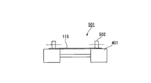
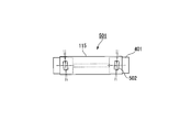
- FIGS. 2 to 5 show configuration examples of the nip roller type nipping and conveying mechanism 501 in the atomic layer deposition winding film forming apparatus 100 of the present embodiment.
- FIG. 2 is a perspective view of the nip roller type nipping / conveying mechanism 501.
- 3 and 4 are cross-sectional views of the nip roller type nipping and conveying mechanism.
- FIG. 5 is a plan view of the nip roller type nipping and conveying mechanism 501.
- the nip roller type nipping and conveying mechanism 501 applies tension to the laminated base material 115 that can be wound. That is, the laminate base material 115 is pulled along the transport direction. Thereby, the slack of the laminate base material 115 is corrected, or the meandering is corrected.
- a greater effect can be obtained.
- the material of the guide roller 401 and the nip roller 502 is a material that can hold both ends in the width direction of the laminate base material 115 and can be conveyed while maintaining an appropriate frictional force necessary for the conveyance with the laminate base material 115. If it is, it will not be specifically limited.
- the conveyance speed of the laminate base material 115 in the first zone 201 is calculated from the saturation adsorption time and the passage distance so that the time for the laminate base material 115 to pass through the first zone 201 is longer than the saturation adsorption time.
- the saturated adsorption time is a time until the amount of the first precursor adsorbed on the film forming surface of the laminate base 115 is saturated.
- the tension during the conveyance of the laminate base material 115 is appropriately set so that the laminate base material 115 does not come into contact with the openings 106, 107a, and 107b.
- the material constituting the second precursor is appropriately selected according to the target deposition material.
- the target deposition material is aluminum oxide, water, ozone, and atomic oxygen are used.
- the material shown by the nonpatent literature 1 can be used, for example.
- the rotation axis of the nip roller 502 is varied so that the rotation axis direction of the nip roller 502 is inclined with respect to the rotation axis direction of the guide roller 401.
- the rotation axis of the guide roller 401 is varied so that the rotation axis direction of the nip roller 502 is inclined with respect to the rotation axis direction of the guide roller 401.
- the rotation axis direction of one of the nip rollers 502 arranged to face each other is inclined with respect to the rotation axis direction of the other roller.
- the rotation axis directions of both the nip rollers 502 arranged so as to face each other are inclined with respect to the rotation axis direction of the guide roller 401.
- FIG. 6 and 7 are diagrams showing the configuration of the guide rail when the atomic layer deposition winding film forming apparatus 100 is used.
- FIG. 6 is a perspective view showing a position close to the opening when a guide rail is used.
- FIG. 7 is a sectional view of the guide rail.
- the carrier laminate substrate 113 on the back side is peeled off. Therefore, it is possible to manufacture a base material in which atomic layer deposition is performed only on one side and no atomic layer is deposited on the back side.
- Example 1 A polyester film having a thickness of 25 ⁇ m was used as the substrate 105 that can be wound using the atomic layer deposition winding film forming apparatus 100 shown in FIG. In addition, a polyester film having a thickness of 75 ⁇ m was used as the carrier laminate substrate 113.
- the laminated rollable base material 115 was conveyed to the third zone 203 and conveyed to the first zone 201 via the guide roller 401c and the nip roller 502c of the third zone 203.
- the conveyance was performed in a state in which the conveyance tension of the laminated and rollable base material 115 when entering the first zone 201 was set to 50 N / width.
- the polyester film saturated with trimethylaluminum on both sides was conveyed again to the third zone 203.
- Nitrogen gas was introduced into the third zone 203 as an inert gas.
- the gas flow rate 303 was adjusted so that the pressure in the third zone 203 was approximately 50.5 Pa. While traveling through the third zone 203, excess trimethylaluminum was purged. After sufficient purging, the sheet was conveyed to the second zone 202 by the guide roller 401c and the nip roller 502c in the third zone 203.
- Nitrogen gas used as the carrier gas and ion-exchanged water used as the second precursor were introduced into the second zone 202.
- the flow rate 302 of the gas supplied to the second zone 202 and the exhaust (decompression) amount 304b by the dry pump were adjusted so that the pressure in the second zone 22 was approximately 50 Pa. While moving in the second zone 202 by the guide roller 401b and the nip roller 502b, trimethylaluminum on both sides of the polyester film reacted with ion-exchanged water, and one atomic layer was deposited on the substrate.
- the conveyance speed of the polyester film was determined by the required purge time in the third zone 203.
- the temperatures of the first zone 201, the second zone 202, and the third zone 203 were all maintained at 90 ° C.
- the atomic layer deposition winding film forming apparatus 100 shown in FIG. 1 there is shown an apparatus in which three cycles of atomic layer deposition are performed by one transport.
- an apparatus capable of 100 cycles was prepared, and 100 cycles of atomic layer deposition were performed.
- the thickness of the aluminum oxide film formed on the polyester film was 10 nm. Neither buckling nor rubbing with the opening 107 was confirmed on the laminated and rollable substrate 115 being conveyed. Moreover, as a result of observing the damage of the surface using an electron microscope, the damage of the surface of the aluminum oxide film was not recognized. Further, the water vapor permeability of the aluminum oxide film was measured.
- the polyester film as the rollable substrate 105 was attached to the position of the unwinding roller 101. Then, it was transported to the third zone 203 and transported to the first zone 201 through the guide roller 401c and the nip roller 502c of the third zone 203. The conveyance was performed in a state where the conveyance tension of the rollable base material 105 was set to 50 N / width.
- first zone 201 nitrogen gas used as a carrier gas and trimethylaluminum used as a first precursor were introduced.
- the flow rate 301 of the gas supplied to the first zone 201 and the exhaust (decompression) amount 304a by the dry pump were adjusted so that the pressure in the first zone 201 was approximately 50 Pa.
- saturated adsorption of trimethylaluminum was performed on both surfaces of the polyester film.
- the polyester film saturated with trimethylaluminum on both sides was conveyed again to the third zone 203.
- Nitrogen gas was introduced into the third zone 203 as an inert gas.
- the gas flow rate 303 was adjusted so that the pressure in the third zone 203 was approximately 50.5 Pa. While traveling through the third zone 203, excess trimethylaluminum was purged. After sufficient purging, the sheet was conveyed to the second zone 202 by the guide roller 401c and the nip roller 502c in the third zone 203.
- the atomic layer deposition winding film forming apparatus 100 shown in FIG. 1 there is shown an apparatus in which three cycles of atomic layer deposition are performed by one transport.
- an apparatus capable of 100 cycles was prepared, and 100 cycles of atomic layer deposition were performed.
- the polyester film as the rollable substrate 105 was attached to the position of the unwinding roller 101. Then, it was transported to the third zone 203 and transported to the first zone 201 through the guide roller 401c and the nip roller 502c of the third zone 203. The conveyance was performed in a state where the conveyance tension of the rollable base material 105 was set to 10 N / width.
- the conveyance speed of the polyester film was determined by the required purge time in the third zone 203.
- the temperatures of the first zone 201, the second zone 202, and the third zone 203 were all maintained at 90 ° C.
- the atomic layer deposition winding film forming apparatus 100 shown in FIG. 1 there is shown an apparatus in which three cycles of atomic layer deposition are performed by one transport.
- an apparatus capable of 100 cycles was prepared, and 100 cycles of atomic layer deposition were performed.
- Example 1 The water vapor permeability measurement of the aluminum oxide films in Example 1 and Comparative Examples 1 and 2 was performed by the following method.
- the water vapor permeability was measured by the MOCON method (same pressure method).
- the measuring instrument used was measured at 40 ° C. and 90% Rh by MOCON AQUATRAN model 1 (an ultra-sensitive water vapor permeability measuring device AQUATRAN manufactured by MOCON).
- Table 1 shows the water vapor permeability of the aluminum oxide films in Example 1, Comparative Example 1, and Comparative Example 2, and the occurrence of scratches.
- Example 1 where the bonding was performed, there was no scratch and the water vapor permeability was low.
- Example 2 A polyester film having a thickness of 25 ⁇ m was used as the substrate 105 by using the atomic layer deposition winding film forming apparatus 100 shown in FIG. Further, as the conveyance auxiliary material 113, a polyester film with an adhesive having a thickness of 50 ⁇ m and an adhesive force of 0.2 N / 25 mm with respect to polyethylene terephthalate (PET) was used. In addition, the conveyance auxiliary material 113 is a conveyance auxiliary material that has already been peeled off and wound after being bonded to another base material twice.
- PET polyethylene terephthalate
- first zone 201 nitrogen gas used as a carrier gas and trimethylaluminum used as a first precursor were introduced.
- the displacement of the first zone 201 and the flow rate of the first precursor were adjusted so that the pressure in the first zone 201 was approximately 50 Pa.
- Saturated adsorption of trimethylaluminum was performed on both sides of the polyester film while moving in the first zone 201 by the guide roller 401a and the nip roller 502a.
- the polyester film saturated with trimethylaluminum on both sides was conveyed again to the third zone 203.
- Nitrogen gas was introduced into the third zone 203 as an inert gas.
- the flow rate of the inert gas in the third zone 203 was adjusted so that the pressure in the third zone 203 was approximately 50.5 Pa. While traveling through the third zone 203, excess trimethylaluminum was purged. After sufficient purging, the polyester film was conveyed to the second zone 202 by the guide roller 401 c and the nip roller 502 c in the third zone 203.
- the thickness of the aluminum oxide film formed on the polyester film was 10 nm. Neither buckling nor rubbing with the opening 107 was confirmed on the laminated and rollable substrate 115 being conveyed. Further, the water vapor permeability of the formed aluminum oxide film was measured.
- a polyester film having a thickness of 25 ⁇ m was used as the substrate 105 by using the atomic layer deposition winding film forming apparatus 100 shown in FIG. Further, as the conveyance auxiliary material 113, a polyester film with an adhesive having a thickness of 38 ⁇ m and an adhesive force of 0.5 N / 25 mm with respect to polyethylene terephthalate (PET) was used. In addition, the conveyance auxiliary material 113 is a conveyance auxiliary material that has already been peeled off and wound after being bonded to another base material twice.
- PET polyethylene terephthalate
- first zone 201 nitrogen gas used as a carrier gas and trimethylaluminum used as a first precursor were introduced.
- the displacement of the first zone 201 and the flow rate of the first precursor were adjusted so that the pressure in the first zone 201 was approximately 50 Pa.
- Saturated adsorption of trimethylaluminum was performed on both sides of the polyester film while moving in the first zone 201 by the guide roller 401a and the nip roller 502a.
- the conveyance speed of the polyester film was determined by the required purge time in the third zone 203.
- the temperatures of the first zone 201, the second zone 202, and the third zone 203 were all maintained at 90 ° C.
- the polyester film as the base material 105 attached to the position of the unwinding roll 101 was conveyed to the third zone 203 and conveyed to the first zone 201 through the guide roller 401c and the nip roller 502c of the third zone 203. It conveyed in the state which set the conveyance tension of the base material 105 at the time of approaching to the 1st zone 201 as 50 N / width.
- the polyester film saturated with trimethylaluminum on both sides was conveyed again to the third zone 203.
- Nitrogen gas was introduced into the third zone 203 as an inert gas.
- the gas flow rate in the third zone 203 was adjusted so that the pressure in the third zone 203 was approximately 50.5 Pa. While traveling through the third zone 203, excess trimethylaluminum was purged. After sufficient purging, the polyester film was conveyed to the second zone 202 by the guide roller 401 c and the nip roller 502 c in the third zone 203.
- the polyester film saturated with trimethylaluminum on both sides was conveyed again to the third zone 203.
- Nitrogen gas was introduced into the third zone 203 as an inert gas.
- the gas flow rate in the third zone 203 was adjusted so that the pressure in the third zone 203 was approximately 50.5 Pa. While traveling through the third zone 203, excess trimethylaluminum was purged. After sufficient purging, the polyester film was conveyed to the second zone 202 by the guide roller 401 c and the nip roller 502 c in the third zone 203.
- the thickness of the aluminum oxide film formed on the polyester film was 10 nm. Although buckling was confirmed in the base material 105 during conveyance, rubbing with the opening 107 was not confirmed. Further, the water vapor permeability of the aluminum oxide film was measured.
Landscapes
- Chemical & Material Sciences (AREA)
- General Chemical & Material Sciences (AREA)
- Chemical Kinetics & Catalysis (AREA)
- Engineering & Computer Science (AREA)
- Materials Engineering (AREA)
- Mechanical Engineering (AREA)
- Metallurgy (AREA)
- Organic Chemistry (AREA)
- Chemical Vapour Deposition (AREA)
- Physical Vapour Deposition (AREA)
Abstract
Un appareil de formation de film d'enroulement permettant un dépôt de couche atomique comprend : un dispositif de déroulement conçu de telle sorte qu'un substrat et un matériau facilitant le transport sont déroulés, qu'un élément sur lequel doit être formé un film dans lequel ledit matériau facilitant le transport a été stratifié de manière décollable sur une surface du substrat est formé et que ledit élément sur lequel le film doit être formé est distribué ; une première chambre à air à dépression dans laquelle un premier gaz précurseur est introduit ; une deuxième chambre à air à dépression dans laquelle un second gaz précurseur est introduit ; une troisième chambre à air à dépression située entre les première et deuxième chambres à air à dépression et dans laquelle un gaz de purge est introduit ; un mécanisme de transport pourvu de parties de maintien conçues pour maintenir les deux bords dans le sens de la largeur de l'élément sur lequel le film doit être formé et conçu pour transporter l'élément sur lequel le film doit être formé jusqu'aux première, deuxième et troisième chambres à air à dépression ; et un dispositif d'enroulement conçu pour enrouler le substrat de l'élément sur lequel le film est formé et qui a été distribué par le mécanisme de transport. Le mécanisme de transport déplace l'élément sur lequel le film est formé à travers les première et deuxième chambres à air à dépression alternativement et à maintes reprises de façon à déposer une couche atomique sur l'autre surface du substrat dans l'élément sur lequel le film est formé et à former un film de dépôt de couche atomique.
Priority Applications (1)
| Application Number | Priority Date | Filing Date | Title |
|---|---|---|---|
| JP2017529557A JPWO2017014092A1 (ja) | 2015-07-17 | 2016-07-11 | 原子層堆積巻き取り成膜装置、原子層堆積方法 |
Applications Claiming Priority (4)
| Application Number | Priority Date | Filing Date | Title |
|---|---|---|---|
| JP2015-143154 | 2015-07-17 | ||
| JP2015143154 | 2015-07-17 | ||
| JP2015252575 | 2015-12-24 | ||
| JP2015-252575 | 2015-12-24 |
Publications (1)
| Publication Number | Publication Date |
|---|---|
| WO2017014092A1 true WO2017014092A1 (fr) | 2017-01-26 |
Family
ID=57833920
Family Applications (1)
| Application Number | Title | Priority Date | Filing Date |
|---|---|---|---|
| PCT/JP2016/070445 Ceased WO2017014092A1 (fr) | 2015-07-17 | 2016-07-11 | Appareil de formation de film d'enroulement permettant un dépôt de couche atomique et procédé de dépôt de couche atomique |
Country Status (2)
| Country | Link |
|---|---|
| JP (1) | JPWO2017014092A1 (fr) |
| WO (1) | WO2017014092A1 (fr) |
Cited By (1)
| Publication number | Priority date | Publication date | Assignee | Title |
|---|---|---|---|---|
| JP2019160940A (ja) * | 2018-03-09 | 2019-09-19 | 凸版印刷株式会社 | 原子層堆積装置および原子層堆積方法 |
Citations (6)
| Publication number | Priority date | Publication date | Assignee | Title |
|---|---|---|---|---|
| JPS5589335A (en) * | 1978-12-27 | 1980-07-05 | Ootsuki Shoten:Kk | Production of metallized sheet |
| JPS5922931A (ja) * | 1982-07-30 | 1984-02-06 | Teijin Ltd | 薄膜の製造方法及び装置 |
| JPS5956429A (ja) * | 1982-09-27 | 1984-03-31 | Sumitomo Bakelite Co Ltd | プラスチツクフイルムの蒸着方法 |
| JP2006028609A (ja) * | 2004-07-20 | 2006-02-02 | Konica Minolta Holdings Inc | 薄膜形成装置及び薄膜形成方法 |
| JP2012169358A (ja) * | 2011-02-10 | 2012-09-06 | Toyota Motor Corp | 金属化フィルムの製造方法および金属化フィルムの製造装置 |
| WO2013180005A1 (fr) * | 2012-05-31 | 2013-12-05 | 凸版印刷株式会社 | Dispositif de formation de film roulé |
-
2016
- 2016-07-11 JP JP2017529557A patent/JPWO2017014092A1/ja active Pending
- 2016-07-11 WO PCT/JP2016/070445 patent/WO2017014092A1/fr not_active Ceased
Patent Citations (6)
| Publication number | Priority date | Publication date | Assignee | Title |
|---|---|---|---|---|
| JPS5589335A (en) * | 1978-12-27 | 1980-07-05 | Ootsuki Shoten:Kk | Production of metallized sheet |
| JPS5922931A (ja) * | 1982-07-30 | 1984-02-06 | Teijin Ltd | 薄膜の製造方法及び装置 |
| JPS5956429A (ja) * | 1982-09-27 | 1984-03-31 | Sumitomo Bakelite Co Ltd | プラスチツクフイルムの蒸着方法 |
| JP2006028609A (ja) * | 2004-07-20 | 2006-02-02 | Konica Minolta Holdings Inc | 薄膜形成装置及び薄膜形成方法 |
| JP2012169358A (ja) * | 2011-02-10 | 2012-09-06 | Toyota Motor Corp | 金属化フィルムの製造方法および金属化フィルムの製造装置 |
| WO2013180005A1 (fr) * | 2012-05-31 | 2013-12-05 | 凸版印刷株式会社 | Dispositif de formation de film roulé |
Cited By (1)
| Publication number | Priority date | Publication date | Assignee | Title |
|---|---|---|---|---|
| JP2019160940A (ja) * | 2018-03-09 | 2019-09-19 | 凸版印刷株式会社 | 原子層堆積装置および原子層堆積方法 |
Also Published As
| Publication number | Publication date |
|---|---|
| JPWO2017014092A1 (ja) | 2018-04-26 |
Similar Documents
| Publication | Publication Date | Title |
|---|---|---|
| JP5713038B2 (ja) | フィルムの製造方法 | |
| JP6119745B2 (ja) | 巻き取り成膜装置 | |
| CN104583102B (zh) | 玻璃膜输送装置 | |
| JP2011194585A (ja) | 機能性フィルムの製造方法 | |
| WO2013145943A1 (fr) | Film barrière contre les gaz et procédé de production de film barrière contre les gaz | |
| TW201413343A (zh) | 光學顯示面板之連續製造方法及光學顯示面板之連續製造系統 | |
| WO2017014092A1 (fr) | Appareil de formation de film d'enroulement permettant un dépôt de couche atomique et procédé de dépôt de couche atomique | |
| KR20160048931A (ko) | 기능성 필름 및 기능성 필름의 제조 방법 | |
| CN221063361U (zh) | 涂布设备 | |
| JP2012219322A (ja) | 巻取式成膜装置及び巻取式成膜方法 | |
| JP2009179446A (ja) | 巻取装置および巻取部材の作製方法 | |
| JP2011207125A (ja) | 機能性フィルム | |
| CN117427850A (zh) | 涂布设备 | |
| CN117460858A (zh) | 用于制造复合膜的设备和方法 | |
| JP2014129565A (ja) | 成膜装置 | |
| JP2014074221A (ja) | 真空成膜装置及び真空成膜方法 | |
| JP7291606B2 (ja) | 成膜装置 | |
| CN223576588U (zh) | 一种卷绕装置及镀膜设备 | |
| CN120117452B (zh) | 一种薄层产品的粘贴吸附、动平衡剥离的上料方法 | |
| JP6896848B2 (ja) | 貼合方法および貼合装置 | |
| JP2002254587A (ja) | 積層体の製造方法及び積層体 | |
| JP2020063467A (ja) | 薄膜形成装置 | |
| JP2006193757A (ja) | 多層薄膜成膜装置及びそれを用いた多層薄膜の製造方法 |
Legal Events
| Date | Code | Title | Description |
|---|---|---|---|
| 121 | Ep: the epo has been informed by wipo that ep was designated in this application |
Ref document number: 16827653 Country of ref document: EP Kind code of ref document: A1 |
|
| ENP | Entry into the national phase |
Ref document number: 2017529557 Country of ref document: JP Kind code of ref document: A |
|
| NENP | Non-entry into the national phase |
Ref country code: DE |
|
| 122 | Ep: pct application non-entry in european phase |
Ref document number: 16827653 Country of ref document: EP Kind code of ref document: A1 |