WO2017014116A1 - Dispositif de commande d'évitement de collision destiné à un véhicule, et procédé de commande d'évitement de collision - Google Patents
Dispositif de commande d'évitement de collision destiné à un véhicule, et procédé de commande d'évitement de collision Download PDFInfo
- Publication number
- WO2017014116A1 WO2017014116A1 PCT/JP2016/070618 JP2016070618W WO2017014116A1 WO 2017014116 A1 WO2017014116 A1 WO 2017014116A1 JP 2016070618 W JP2016070618 W JP 2016070618W WO 2017014116 A1 WO2017014116 A1 WO 2017014116A1
- Authority
- WO
- WIPO (PCT)
- Prior art keywords
- deceleration
- brake
- control
- collision avoidance
- vehicle
- Prior art date
- Legal status (The legal status is an assumption and is not a legal conclusion. Google has not performed a legal analysis and makes no representation as to the accuracy of the status listed.)
- Ceased
Links
Images



Classifications
-
- B—PERFORMING OPERATIONS; TRANSPORTING
- B60—VEHICLES IN GENERAL
- B60T—VEHICLE BRAKE CONTROL SYSTEMS OR PARTS THEREOF; BRAKE CONTROL SYSTEMS OR PARTS THEREOF, IN GENERAL; ARRANGEMENT OF BRAKING ELEMENTS ON VEHICLES IN GENERAL; PORTABLE DEVICES FOR PREVENTING UNWANTED MOVEMENT OF VEHICLES; VEHICLE MODIFICATIONS TO FACILITATE COOLING OF BRAKES
- B60T7/00—Brake-action initiating means
- B60T7/12—Brake-action initiating means for automatic initiation; for initiation not subject to will of driver or passenger
- B60T7/22—Brake-action initiating means for automatic initiation; for initiation not subject to will of driver or passenger initiated by contact of vehicle, e.g. bumper, with an external object, e.g. another vehicle, or by means of contactless obstacle detectors mounted on the vehicle
-
- B—PERFORMING OPERATIONS; TRANSPORTING
- B60—VEHICLES IN GENERAL
- B60T—VEHICLE BRAKE CONTROL SYSTEMS OR PARTS THEREOF; BRAKE CONTROL SYSTEMS OR PARTS THEREOF, IN GENERAL; ARRANGEMENT OF BRAKING ELEMENTS ON VEHICLES IN GENERAL; PORTABLE DEVICES FOR PREVENTING UNWANTED MOVEMENT OF VEHICLES; VEHICLE MODIFICATIONS TO FACILITATE COOLING OF BRAKES
- B60T7/00—Brake-action initiating means
- B60T7/02—Brake-action initiating means for personal initiation
- B60T7/04—Brake-action initiating means for personal initiation foot actuated
- B60T7/042—Brake-action initiating means for personal initiation foot actuated by electrical means, e.g. using travel or force sensors
-
- B—PERFORMING OPERATIONS; TRANSPORTING
- B60—VEHICLES IN GENERAL
- B60T—VEHICLE BRAKE CONTROL SYSTEMS OR PARTS THEREOF; BRAKE CONTROL SYSTEMS OR PARTS THEREOF, IN GENERAL; ARRANGEMENT OF BRAKING ELEMENTS ON VEHICLES IN GENERAL; PORTABLE DEVICES FOR PREVENTING UNWANTED MOVEMENT OF VEHICLES; VEHICLE MODIFICATIONS TO FACILITATE COOLING OF BRAKES
- B60T7/00—Brake-action initiating means
- B60T7/12—Brake-action initiating means for automatic initiation; for initiation not subject to will of driver or passenger
-
- B—PERFORMING OPERATIONS; TRANSPORTING
- B60—VEHICLES IN GENERAL
- B60T—VEHICLE BRAKE CONTROL SYSTEMS OR PARTS THEREOF; BRAKE CONTROL SYSTEMS OR PARTS THEREOF, IN GENERAL; ARRANGEMENT OF BRAKING ELEMENTS ON VEHICLES IN GENERAL; PORTABLE DEVICES FOR PREVENTING UNWANTED MOVEMENT OF VEHICLES; VEHICLE MODIFICATIONS TO FACILITATE COOLING OF BRAKES
- B60T8/00—Arrangements for adjusting wheel-braking force to meet varying vehicular or ground-surface conditions, e.g. limiting or varying distribution of braking force
- B60T8/17—Using electrical or electronic regulation means to control braking
- B60T8/171—Detecting parameters used in the regulation; Measuring values used in the regulation
-
- B—PERFORMING OPERATIONS; TRANSPORTING
- B60—VEHICLES IN GENERAL
- B60T—VEHICLE BRAKE CONTROL SYSTEMS OR PARTS THEREOF; BRAKE CONTROL SYSTEMS OR PARTS THEREOF, IN GENERAL; ARRANGEMENT OF BRAKING ELEMENTS ON VEHICLES IN GENERAL; PORTABLE DEVICES FOR PREVENTING UNWANTED MOVEMENT OF VEHICLES; VEHICLE MODIFICATIONS TO FACILITATE COOLING OF BRAKES
- B60T8/00—Arrangements for adjusting wheel-braking force to meet varying vehicular or ground-surface conditions, e.g. limiting or varying distribution of braking force
- B60T8/32—Arrangements for adjusting wheel-braking force to meet varying vehicular or ground-surface conditions, e.g. limiting or varying distribution of braking force responsive to a speed condition, e.g. acceleration or deceleration
- B60T8/321—Arrangements for adjusting wheel-braking force to meet varying vehicular or ground-surface conditions, e.g. limiting or varying distribution of braking force responsive to a speed condition, e.g. acceleration or deceleration deceleration
- B60T8/3255—Systems in which the braking action is dependent on brake pedal data
-
- G—PHYSICS
- G08—SIGNALLING
- G08G—TRAFFIC CONTROL SYSTEMS
- G08G1/00—Traffic control systems for road vehicles
- G08G1/16—Anti-collision systems
-
- B—PERFORMING OPERATIONS; TRANSPORTING
- B60—VEHICLES IN GENERAL
- B60T—VEHICLE BRAKE CONTROL SYSTEMS OR PARTS THEREOF; BRAKE CONTROL SYSTEMS OR PARTS THEREOF, IN GENERAL; ARRANGEMENT OF BRAKING ELEMENTS ON VEHICLES IN GENERAL; PORTABLE DEVICES FOR PREVENTING UNWANTED MOVEMENT OF VEHICLES; VEHICLE MODIFICATIONS TO FACILITATE COOLING OF BRAKES
- B60T2201/00—Particular use of vehicle brake systems; Special systems using also the brakes; Special software modules within the brake system controller
- B60T2201/02—Active or adaptive cruise control system; Distance control
- B60T2201/022—Collision avoidance systems
-
- B—PERFORMING OPERATIONS; TRANSPORTING
- B60—VEHICLES IN GENERAL
- B60T—VEHICLE BRAKE CONTROL SYSTEMS OR PARTS THEREOF; BRAKE CONTROL SYSTEMS OR PARTS THEREOF, IN GENERAL; ARRANGEMENT OF BRAKING ELEMENTS ON VEHICLES IN GENERAL; PORTABLE DEVICES FOR PREVENTING UNWANTED MOVEMENT OF VEHICLES; VEHICLE MODIFICATIONS TO FACILITATE COOLING OF BRAKES
- B60T2220/00—Monitoring, detecting driver behaviour; Signalling thereof; Counteracting thereof
- B60T2220/04—Pedal travel sensor, stroke sensor; Sensing brake request
Definitions
- the present invention relates to a vehicle collision avoidance control device and a collision avoidance control method.
- one of the objects of the present invention is to provide a vehicle collision avoidance control device and a collision avoidance control method capable of realizing the requested braking even when the driver performs a brake operation during the execution of the collision avoidance control. Is to provide.
- the collision avoidance control apparatus for a vehicle inputs a vehicle body deceleration that is an actual deceleration of a traveling vehicle, and inputs the vehicle body deceleration, a relative distance to an obstacle, a target relative distance, A collision avoidance control unit for obtaining a first required deceleration for avoiding a collision with the obstacle, and a first control based on the input vehicle body deceleration and the first required deceleration And the second control based on the first required deceleration, the required deceleration for controlling the brake device is obtained, and when the braking operation by the driver is detected, the first control is stopped. And a brake control unit.
- the requested braking can be realized even when the driver performs a braking operation during the execution of the collision avoidance control.
- the brake control unit resumes the first control when the braking operation is no longer detected.
- this configuration makes it possible to realize appropriate collision avoidance control when the driver stops the brake operation after performing the brake operation during the execution of the collision avoidance control.
- the brake control unit when the braking operation is detected, the second requested deceleration which is the requested deceleration by the braking operation, and the first The third required deceleration which is a deceleration obtained by feeding back the required deceleration with the vehicle body deceleration is compared, and the brake device is controlled with the larger deceleration. According to this configuration, as an example, even when the braking force by the driver's braking operation is small during the collision avoidance control, it is possible to reliably avoid the collision with the obstacle.
- a vehicle body deceleration that is an actual deceleration of a traveling vehicle is input, the input vehicle body deceleration, a relative distance to an obstacle, a target relative distance, A first request deceleration for avoiding a collision with the obstacle is obtained based on the first control based on the inputted vehicle body deceleration and the first requested deceleration; And a second control based on the requested deceleration of 1 includes obtaining a requested deceleration for controlling the brake device, and stopping the first control when a braking operation by the driver is detected. .
- the requested braking can be realized even when the driver performs a braking operation during the execution of the collision avoidance control.
- FIG. 1 is an exemplary schematic diagram of a vehicle on which the collision avoidance control device for a vehicle according to the embodiment is mounted.
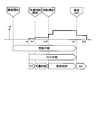
- FIG. 2 is an exemplary explanatory diagram illustrating transition of the control state by the vehicle collision avoidance control device of the embodiment.
- FIG. 3 is an exemplary schematic block diagram of the vehicle collision avoidance control apparatus according to the embodiment.
- FIG. 4 is a flowchart illustrating an example of the procedure of the collision avoidance control process according to the first embodiment.
- FIG. 5 is a flowchart illustrating an example of the procedure of the collision avoidance control process according to the second embodiment.
- FIG. 6 is a diagram showing a change in deceleration in the second embodiment.
- each part of the vehicle 100 is controlled to avoid a collision with an obstacle ahead while the vehicle 100 is traveling forward is illustrated.
- FIG. 1 is an exemplary schematic diagram of a vehicle 100 according to the first embodiment.
- the vehicle 100 includes an engine 51, a motor generator 62 (M / G), a brake device 41, and the like.
- Engine 51 and motor generator 62 cause acceleration of vehicle 100. Therefore, the engine 51 and the motor generator 62 can also be referred to as drive sources or drive devices.
- the vehicle 100 only needs to be equipped with at least one of the engine 51 and the motor generator 62 as a drive source.
- the acceleration of the vehicle 100 is an increase over time of the speed toward the front of the vehicle 100 (time differentiation), and the deceleration of the vehicle 100 is a decrease over time of the speed toward the front of the vehicle 100 (time differentiation). ).
- the acceleration is also a negative deceleration
- the deceleration is also a negative acceleration. That is, the acceleration increases when the braking force or deceleration by the brake device 41 decreases, and the deceleration increases when the driving force or acceleration by the engine 51 or the motor generator 62 decreases.
- the vehicle 100 includes a PCS-ECU 10 (pre-crash safety electronic control unit) and a brake ECU 40.
- the PCS-ECU 10 and the brake ECU 40 are examples of a collision avoidance control device.
- the PCS-ECU 10 determines whether or not there is a possibility of a collision with the obstacle.
- the brake ECU 40, the engine ECU 50, the M / G ECU 60, and the like that control the brake device 41, the engine 51, the motor generator 62, and the like are instructed so as to avoid a collision with an obstacle.
- the PCS-ECU 10 is an example of a collision avoidance control device. In this embodiment, the PCS-ECU 10 instructs to control the acceleration or deceleration of the vehicle 100, that is, the driving force or the braking force, but the PCS-ECU 10 further controls the steering of the vehicle 100. You may instruct.
- the PCS-ECU 10 includes a control unit such as a CPU (central processing unit) and a controller, and a storage unit such as a ROM (read only memory), a RAM (random access memory), and a flash memory.
- the storage unit can store a program for operating the PCS-ECU 10, data used for arithmetic processing of the PCS-ECU 10, and the like.
- the vehicle 100 is equipped with a distance measuring device 21, a camera 22, an acceleration sensor 23, and a brake operation detection unit 24.
- the distance measuring device 21 is a device that wirelessly measures the distance to the obstacle without contact, and is, for example, a radar device or a sonar device.
- the PCS-ECU 10 acquires data indicating the distance from the obstacle from the distance measuring device 21.
- the data indicating the distance may be numerical data indicating the distance itself, or may be data having a value corresponding to the distance.
- the camera 22 is a digital camera incorporating an image sensor such as a CCD (charge coupled device) or a CIS (CMOS image sensor).
- the camera 22 can output moving image data at a predetermined frame rate.
- the PCS-ECU 10 may acquire data indicating an image captured by the camera 22 and acquire the distance to the obstacle using the image data.
- the acceleration sensor 23 detects the longitudinal acceleration (longitudinal acceleration) of the vehicle body and outputs a signal representing the longitudinal acceleration.
- PCS-ECU 10 receives data indicating detection results from the various sensors from various sensors mounted on vehicle 100.
- the sensor mounted on the vehicle 100 may include a sensor that indicates a detection result of the state of the vehicle 100.
- a sensor indicating the detection result of the state of the vehicle 100 is, for example, a vehicle speed sensor, a gyro sensor, or the like in addition to the acceleration sensor 23 described above.
- the sensor mounted on the vehicle 100 may include a sensor that indicates a detection result of an operation amount or an operation request amount in an operation unit operated by a driver.
- the operation unit by the driver is, for example, an accelerator pedal, a brake pedal, a brake handle, a steering wheel, a switch, or the like.
- the brake operation detection unit 24 is provided in the brake pedal and detects an operation of the brake pedal by the driver.
- Examples of the brake operation detection unit 24 include a brake switch, a brake pedal stroke sensor, and a pedaling force sensor.
- the brake switch outputs a brake operation signal indicating whether or not the driver has operated the brake pedal. Specifically, the brake switch outputs an on (High) brake operation signal when the brake pedal is operated, and an off (Low) brake operation signal when the brake pedal is not operated. Output.
- the brake pedal stroke sensor detects the depression amount (stroke amount) of the brake pedal by the driver and sends a detection signal.
- the pedal force sensor detects a brake pedal force or a pedal operating force when the brake pedal is depressed, and sends a detection signal.
- the brake operation signal and each detection signal are output to the brake ECU 40.
- the sensor mounted on the vehicle 100 may include a sensor that indicates the detection result of the state of each device mounted on the vehicle 100.
- Devices mounted on the vehicle 100 are, for example, a brake device 41, an engine 51, a motor generator 62, an inverter 61 (IV), a steering system, a suspension system, and the like.
- the physical quantities detected by various sensors mounted on the vehicle 100 are, for example, distance, displacement, speed, acceleration, rotational speed, angle, angular velocity, angular acceleration, and the like.
- the PCS-ECU 10 may be input with numerical data indicating each physical quantity itself, or may be input with data corresponding to the magnitude of each physical quantity.
- the data input to the PCS-ECU 10 may be digital data, analog data such as non-numerical potentials, or data corresponding to on / off and stages instead of physical values. There may be.
- the PCS-ECU 10 calculates a predicted time to collide with an obstacle ahead, that is, TTC (time to collision) when performing collision avoidance control.
- TTC time to collision
- the TTC may be calculated in consideration of the relative acceleration of the obstacle, the deceleration of the vehicle 100, and the like.
- the PCS-ECU 10 calculates the share of the acceleration or deceleration of the vehicle 100 calculated by the brake ECU 40 by each of the brake device 41, the engine 51, and the motor generator 62.
- the share ratio varies depending on the situation of the vehicle 100, for example.
- the PCS-ECU 10 transmits data indicating acceleration or deceleration shared by the brake ECU 40, engine ECU 50, and M / G (motor generator) ECU 60.
- the brake ECU 40 calculates the acceleration and deceleration of the vehicle 100 from the detection signal from the acceleration sensor 23.
- the brake ECU 40 controls the brake device 41 so that the calculated acceleration or deceleration is obtained.
- the engine ECU 50 controls the engine 51 so that the acceleration or deceleration set by the PCS-ECU 10 can be obtained.
- the M / G ECU 60 controls the inverter 61 so that the motor generator 62 operates so as to obtain the acceleration or deceleration set by the PCS-ECU 10.
- the brake ECU 40 can control the stop lamp 42 provided at the rear end of the vehicle 100 to light up.
- the lighting of the stop lamp 42 can be an alarm display for the surroundings of the vehicle 100, for example, the following vehicle.
- meter ECU70 can control the meter 71 provided in the instrument panel etc. so that a warning display may be output.
- the display output of the meter 71 can be an alarm display for a driver or an occupant in the passenger compartment.
- the stop lamp 42 and the meter 71 can also be referred to as an alarm output device, an output device, an alarm device, a display output device, or the like.
- an audio output can be output from an audio output device (not shown).
- the audio output device is, for example, a speaker or a buzzer, and can also be called an alarm output device, an output device, an alarm device, or the like.
- FIG. 2 shows an example of the transition of the control state in the automatic collision avoidance control when the driver does not perform the brake operation.
- the horizontal axis represents time
- the vertical axis represents deceleration
- ⁇ represents acceleration
- the PCS-ECU 10 calculates TTC at predetermined time intervals based on data acquired while the vehicle 100 is traveling, and starts collision avoidance control or performs collision avoidance control according to this TTC value. To the next stage, or the collision avoidance control is terminated. That is, the PCS-ECU 10 monitors the situation related to collision avoidance based on the TTC.
- the PCS-ECU 10 starts an alarm operation by the meter 71 or a speaker.
- the PCS-ECU 10 instructs the brake ECU 40 to drive a pump (not shown) of the brake device 41.
- the brake ECU 40 performs control based on the instruction and eliminates the gap between the brake pad and the brake disc or drum. This operation can also be referred to as prefill (PF).
- the PCS-ECU 10 instructs the brake ECU 40 to start preliminary braking. Specifically, the PCS-ECU 10 transmits an instruction signal to the brake ECU 40 so that the stop lamp 42 is lit. Further, for example, the PCS-ECU 10 instructs the brake ECU 40 to obtain the minimum necessary deceleration (braking force) accompanying the lighting of the stop lamp 42, and the brake ECU 40 controls the brake device 41 based on the instruction. .
- the main purpose of the preliminary braking is to turn on the stop lamp 42, but a required deceleration that makes the driver of the rear vehicle aware of the deceleration operation may be obtained.
- the PCS-ECU 10 instructs the brake ECU 40 to start braking control for the purpose of avoiding a collision. Specifically, the PCS-ECU 10 instructs the brake ECU 40 to change the speed of the vehicle 100 at a required deceleration, that is, to obtain a required braking force, and the brake ECU 40 sets the brake device 41 based on the instruction. To control. In the braking control, the deceleration (braking force) may increase stepwise.
- the PCS-ECU 10 instructs the brake ECU 40 to maintain the stopped state for a predetermined period, and the brake ECU 40 controls the brake device 41 based on the instruction.
- This operation can also be referred to as a brake hold (BH).
- FIG. 3 is a block diagram illustrating functional configurations of the PCS-ECU 10 and the brake ECU 40 according to the first embodiment.
- the PCS-ECU 10 mainly includes a distance correction unit 11, adders 14 and 15, an FB control unit 13, and an FF control unit 12.
- the PCS-ECU 10 feeds back the vehicle deceleration of the vehicle, uses the vehicle deceleration, the relative distance, and the target relative distance to perform feedback control by the distance correction unit 11, the adder 14, and the FB control unit 13, and the relative speed.
- the PCS required deceleration which is a deceleration necessary for collision avoidance, is obtained by feedforward control by the FF control unit 12 that inputs.
- the PCS-ECU 10 may be an independent ECU, or may be incorporated in an ECU of any system mounted on the vehicle.
- the PCS-ECU 10 can execute processes in accordance with installed and loaded programs to realize each function. That is, by executing the processing according to the program, the PCS-ECU 10 can function as the distance correction unit 11, the adders 14 and 15, the FB control unit 13, the FF control unit 12, and the like. Note that at least some of the functions of the above-described units may be realized by hardware.
- the PCS-ECU 10 inputs a relative distance from an obstacle such as a preceding vehicle from the distance measuring device 21.
- the input relative distance is converted into deceleration by the FF control unit 12, and the value is output to the adder 15.
- the input relative distance is input to the distance correction unit 11.
- the distance correction unit 11 feeds back and inputs the actual vehicle deceleration (actual vehicle deceleration) of the vehicle calculated by the brake ECU 40 from the detection signal of the acceleration sensor 23.
- the distance correction unit 11 corrects the relative distance by a distance corresponding to the fed-back vehicle body deceleration and outputs the corrected relative distance.
- the adder 14 calculates and outputs a difference between the corrected relative distance and a target relative distance set in advance as a target value of the relative distance.
- the FB control unit 13 calculates and outputs a deceleration from the input distance difference.
- the adder 15 outputs a value obtained by adding the deceleration output value from the FF control unit 12 and the deceleration output value from the FB control unit 13 to the brake ECU 40 as a PCS required deceleration.
- the PCS required deceleration is a deceleration required for collision avoidance, and is an example of a first required deceleration. In this manner, the PCS-ECU 10 calculates the PCS required deceleration required for collision avoidance by feeding back the vehicle body deceleration occurring at that time.
- the brake ECU 40 includes a reference deceleration calculation unit 47, an adder 46, an FB control unit 43, an FF control unit 48, a determination unit 45, and a hydraulic pressure conversion unit 44.
- the brake ECU 40 receives a detection signal from the acceleration sensor 23 and calculates an actual vehicle deceleration (actual vehicle deceleration) of the vehicle from the detection signal. This vehicle deceleration is also input to the PCS-ECU 10 as described above.
- the brake ECU 40 may be an independent ECU, or may be incorporated in an ECU of any system mounted on the vehicle.
- the brake ECU 40 can execute processing according to the installed and loaded program to realize each function.
- the brake ECU 40 is configured such that the reference deceleration calculation unit 47, the adder 46, the FB control unit 43, the FF control unit 48, the determination unit 45, and the hydraulic pressure conversion unit. 44 or the like. Note that at least some of the functions of the above-described units may be realized by hardware.
- the brake ECU 40 feeds back the vehicle body deceleration of the vehicle and uses the vehicle body deceleration and the PCS required deceleration to perform feedback control (first control) by the reference deceleration calculating unit 47, the adder 46, and the FB control unit 43. 1) and feedforward control (an example of second control) by the FF control unit 48 that inputs the PCS required deceleration, a brake target deceleration that is a deceleration required for braking is obtained.
- the brake ECU 40 inputs the PCS request deceleration from the PCS-ECU 10. A predetermined calculation is performed by the FF control unit 48 on the input PCS request deceleration, and the output value is output to the determination unit 45.
- the input PCS required deceleration is input to the reference deceleration calculation unit 47.
- the reference deceleration calculation unit 47 outputs, for example, a reference deceleration in which the input value of the stepped PCS required deceleration is set to a predetermined value.
- the adder 46 subtracts the vehicle body deceleration input by feedback from the reference deceleration, the FB control unit 43 performs a predetermined calculation on the subtraction value, and the output value is output to the determination unit 45.
- the determination unit 45 inputs a detection signal of the brake operation by the driver detected by the brake operation detection unit 24, and calculates a driver deceleration that is a deceleration by the driver's brake operation.
- This driver deceleration is an example of a second required deceleration.
- the determination unit 45 inputs the deceleration output value from the FF control unit 48 and the deceleration output value from the FB control unit 43, and adds both.
- the determination unit 45 outputs an addition value of the deceleration output value from the FF control unit 48 and the deceleration output value from the FB control unit 43 from each unit.
- the data are sequentially stored in the memory and sent to the hydraulic pressure conversion unit 44.
- the addition value of the deceleration output value from the FF control unit 48 and the deceleration output value from the FB control unit 43 is a deceleration obtained by feeding back the PCS required deceleration by the vehicle body deceleration. This is called deceleration.
- the brake target deceleration is a deceleration that must be truly generated by the brake device 41.
- the hydraulic pressure conversion unit 44 converts the input hydraulic pressure command to generate the brake target deceleration and sends it to the brake device 41.
- the brake ECU has set the deceleration obtained by adding the driver deceleration, which is the required deceleration by the brake operation, to the brake target deceleration.
- feedback control was performed. For this reason, there are cases where the deceleration of the collision avoidance control becomes smaller than that in the case where the brake operation is not performed.
- the deceleration necessary for collision avoidance is output as a control target. Therefore, if the feedback control is performed by adding the brake target deceleration and the driver deceleration, it is necessary for the collision avoidance. The proportion of the collision avoidance control with respect to the deceleration is reduced, and the deceleration necessary for the collision avoidance is weakened by the amount corresponding to the driver deceleration.
- the control amount (deceleration) required for collision avoidance control varies, so the target value varies and feedback control cannot follow.
- changes in driver deceleration due to the driver's braking operation are delayed and reflected in the actual vehicle deceleration, and then the vehicle deceleration that was fed back in the collision avoidance control is corrected by feedback control and reflected in the final deceleration. End up. For this reason, the response delay with respect to a brake operation is large, and the vehicle body deceleration changes.
- the determination unit 45 detects this driver operation, and the reference deceleration calculation unit 47 and the adder 46 in the brake ECU 40. And feedback control by the FB control unit 43 is stopped. Specifically, when a brake operation is input, the determination unit 45 adds the output value of the FB control unit 43 and the output value of the FF control unit 48 stored in the memory at the time of input (brake target). The driver deceleration by the driver's braking operation is added to the deceleration and output to the hydraulic pressure conversion unit 44, thereby stopping the feedback control by the reference deceleration calculation unit 47, the adder 46, and the FB control unit 43.
- the driver deceleration due to the driver's brake operation is added to the deceleration required for the collision avoidance control and feedback control is performed. Will not be performed. For this reason, the braking required by the driver can be realized without weakening the deceleration required for collision avoidance or causing a response delay.
- the determination unit 45 determines the reference deceleration calculation unit 47, the adder 46, and the FB control unit 43 in the brake ECU 40.
- the feedback control by is resumed.
- the determination unit 45 outputs an addition value (brake target deceleration) of the deceleration output value from the FF control unit 48 and the deceleration output value from the FB control unit 43 from each unit.
- the feedback control by the reference deceleration calculating unit 47, the adder 46, and the FB control unit 43 is resumed by resuming the sequential storage in the internal memory and sending to the hydraulic pressure conversion unit 44.
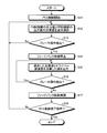
- FIG. 4 is a flowchart illustrating an example of the procedure of the collision avoidance control process according to the first embodiment.
- the PCS-ECU 10 starts collision avoidance control (PCS control) (S11).
- PCS control collision avoidance control
- feedback control and feedforward control by the PCS-ECU 10 and feedback control and feedforward control by the brake ECU 40 are performed.
- the determination unit 45 of the brake ECU 40 sequentially stores the addition value (brake target deceleration) of the output value of the FF control unit 48 and the output value of the FB control unit 43 in a memory and outputs it to the hydraulic pressure conversion unit 44 (S12). ).
- the determination unit 45 determines whether or not a brake operation by the driver has been detected (S13). While the brake operation is not detected (S13: No), S12 repeatedly stores and outputs the added value of the output value of the FF control unit 48 and the output value of the FB control unit 43 by the determination unit 45.
- the brake ECU 40 stops the feedback control by the reference deceleration calculation unit 47, the adder 46, and the FB control unit 43 (S14). That is, the value obtained by adding the driver deceleration by the driver's brake operation to the added value (the added value of the output value of the FB control unit 43 and the output value of the FF control unit 48) stored in the memory at this time is converted into a hydraulic pressure. It outputs to the part 44 (S15). In other words, even if the output value of the FF control unit 48 and the output value of the FB control unit 43 change, the determination unit 45 receives the brake operation stored in the memory without calculating the changed addition value. The value obtained based on the added value at the time is continuously output to the hydraulic pressure conversion unit 44.
- the determination unit 45 determines whether or not a brake operation by the driver has been detected (S16). While the brake operation is detected (S16: Yes), in S15, the determination unit 45 uses a value obtained by adding the driver deceleration to the addition value at the time when the brake operation stored in the memory is input. Continue to output to the conversion unit 44.
- the brake ECU 40 resumes the feedback control by the reference deceleration calculation unit 47, the adder 46, and the FB control unit 43 (S17). That is, the determination unit 45 sequentially adds an addition value of the deceleration output value from the FF control unit 48 and the deceleration output value from the FB control unit 43 to the internal memory each time it is output from each unit. Save and send to hydraulic pressure conversion unit 44.
- the PCS-ECU 10 determines whether or not there has been an instruction to end the collision avoidance control (PCS control) from the driver (S18). If there is no instruction to end the collision avoidance control (S18: No), the processing from S12 to S18 is repeated. If there is an instruction to end the collision avoidance control (PCS control) (S18: Yes), the process ends.
- PCS control end the collision avoidance control
- the required deceleration obtained by feedback control of the PCS required deceleration with the vehicle body deceleration, that is, the brake target deceleration, and the driver's brake The greater one of the requested deceleration due to the operation is output, and even when the braking by the driver's brake operation is a small braking during the execution of the collision avoidance control, the collision avoidance is more reliably realized.
- the configuration of the vehicle 100 and the configuration of the PCS-ECU 10 and the brake ECU 40 of this embodiment are the same as those of the first embodiment.
- the determination unit 45 of the brake ECU 40 of the present embodiment calculates a driver deceleration (an example of a second requested deceleration) that is a requested deceleration due to a brake operation when a brake operation is detected. Then, the determination unit 45 compares the calculated driver deceleration with the deceleration obtained by feeding back the PCS required deceleration by the vehicle body deceleration, that is, the brake target deceleration (an example of the third required deceleration). Is output to the hydraulic pressure conversion unit 44 to control the brake device 41.
- the deceleration (brake target deceleration) obtained by feeding back the PCS required deceleration by the vehicle body deceleration is an added value of the output value of the FF control unit 48 and the output value of the FB control unit 43.
- the brake ECU 40 stops the feedback control by the reference deceleration calculation unit 47, the adder 46, and the FB control unit 43, and sets the driver deceleration. Output to the hydraulic pressure conversion unit 44.
- the brake ECU 40 restarts the feedback control by the reference deceleration calculation unit 47, the adder 46, and the FB control unit 43, and the brake target deceleration is converted into the hydraulic pressure conversion unit 44. Output to.
- FIG. 5 is a flowchart illustrating an example of the procedure of the collision avoidance control process according to the second embodiment.
- the PCS-ECU 10 starts collision avoidance control (PCS control) (S31).
- PCS control collision avoidance control
- feedback control and feedforward control by the PCS-ECU 10 and feedback control and feedforward control by the brake ECU 40 are performed.
- the determination unit 45 of the brake ECU 40 adds the output value of the FF control unit 48 and the output value of the FB control unit 43 (a deceleration obtained by feeding back the PCS required deceleration by the vehicle body deceleration, That is, the brake target deceleration) is sequentially stored in the memory, and the added value is output to the hydraulic pressure conversion unit 44.
- the determination unit 45 determines whether or not a brake operation by the driver has been detected (S32). While the brake operation is not detected (S32: No), the determination unit 45 repeatedly stores and outputs the added value of the output value of the FF control unit 48 and the output value of the FB control unit 43.
- the determination unit 45 calculates the driver deceleration and determines whether the driver deceleration is larger than the brake target deceleration (S33).
- the brake ECU 40 stops the feedback control by the reference deceleration calculation unit 47, the adder 46, and the FB control unit 43 (S34).
- the driver deceleration is output to the hydraulic pressure conversion unit 44 (S35).
- the brake ECU 40 is stopping feedback control by the reference deceleration calculation unit 47, the adder 46, and the FB control unit 43. (S36), the determination unit 45 outputs the brake target deceleration as the brake target deceleration to the hydraulic pressure conversion unit 44 (S37).
- the PCS-ECU 10 determines whether or not there has been an instruction to end the collision avoidance control (PCS control) from the driver (S38). If there is no instruction to end the collision avoidance control (S38: No), the processes from S32 to S38 are repeated. If there is an instruction to end the collision avoidance control (S38: Yes), the process ends.
- PCS control PCS control
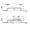
- FIG. 6 is a diagram showing a change in deceleration in the second embodiment.
- FIG. 6A shows a case where there is no brake operation by the driver
- FIG. 6B shows a case where there is a brake operation by the driver.
- the horizontal axis represents time
- the vertical axis represents the magnitude of deceleration.
- Reference numeral 601 indicates a change in the brake target deceleration.
- Reference numeral 602 indicates a change in the vehicle body deceleration of the vehicle 100.
- Reference numeral 603 indicates the PCS request deceleration.
- Reference numeral 604 denotes a driver deceleration due to a brake operation.
- Reference numeral 610 indicates a period in which the feedback control by the reference deceleration calculation unit 47, the adder 46, and the FB control unit 43 in the brake ECU 40 is stopped.
- the PCS-ECU 10 when the PCS control is started, the PCS-ECU 10 outputs the PCS required deceleration 603, and based on this, the brake ECU 40 determines that the brake target deceleration 601 is the PCS required deceleration. A value larger than 603 is output. As a result, the vehicle body deceleration 602 of the vehicle 100 has a magnitude that substantially matches the PCS required deceleration 603.
- the driver performs a brake operation during the PCS control and a driver deceleration 604 is generated.
- the driver deceleration is small and does not exceed the brake target deceleration 601
- the feedback control by the reference deceleration calculation unit 47, the adder 46, and the FB control unit 43 in the brake ECU 40 is continued without being stopped. Therefore, the determination unit 45 outputs the brake target deceleration 601 to the hydraulic pressure conversion unit 44.
- the brake ECU 40 performs the reference deceleration calculation unit 47, the adder 46, and the FB control unit.
- the determination unit 45 outputs the driver deceleration 604 to the hydraulic pressure conversion unit 44 instead of the brake target deceleration 601. Further, when the driver deceleration 604 becomes smaller and becomes smaller than the brake target deceleration 601 (“FB restart”), the brake ECU 40 performs feedback by the reference deceleration calculation unit 47, the adder 46, and the FB control unit 43. Resume control. Therefore, the determination unit 45 outputs the brake target deceleration 601 to the hydraulic pressure conversion unit 44. Since the feedback control is stopped while the driver deceleration 604 is selected, the brake target deceleration 601 is reduced by the feedback control while the driver deceleration 604 larger than the brake target deceleration 601 is selected. Therefore, appropriate control is realized when feedback control is resumed.
- the brake device 41 when braking is performed by a driver's brake operation during the collision avoidance control, the brake device 41 is controlled by the larger of the brake target deceleration and the driver deceleration by the driver's brake operation. To do. For this reason, in this embodiment, braking is applied by the brake operation during the collision avoidance control, and the brake device 41 is controlled even if the feedback control by the reference deceleration calculation unit 47, the adder 46, and the FB control unit 43 is stopped. Therefore, the required deceleration is not reduced, and the vehicle body deceleration is not reduced. For this reason, according to this embodiment, even when the braking force by the brake operation by the driver is small during the collision avoidance control, it is possible to reliably avoid the collision with the obstacle.
- the addition value of the output value of the FB control unit 43 and the output value of the FF control unit 48 is stored, and when a brake operation is detected, the determination unit 45 determines the stored output value of the FB control unit 43 and the FF
- the added value of the output value of the control unit 48 and the driver deceleration are added and output to the hydraulic pressure conversion unit 44.
- only the output value of the FB control unit 43 is stored and stored when the brake operation is detected.
- the output value of the FB control unit 43, the latest output value of the FF control unit 48, and the driver deceleration may be added and output to the hydraulic pressure conversion unit 44.
- PCS-ECU collision avoidance control unit
- brake ECU brake control unit
- 41 brake device.
Landscapes
- Engineering & Computer Science (AREA)
- Transportation (AREA)
- Mechanical Engineering (AREA)
- Physics & Mathematics (AREA)
- General Physics & Mathematics (AREA)
- Regulating Braking Force (AREA)
Abstract
L'invention concerne un dispositif de commande d'évitement de collision destiné à un véhicule, comportant : une unité de commande d'évitement de collision qui introduit la décélération de carrosserie de véhicule, qui est la décélération réelle du véhicule qui se déplace, et calcule une première décélération demandée pour éviter une collision avec un obstacle sur la base de la décélération de carrosserie de véhicule introduite, la distance relative par rapport à l'obstacle, et la distance relative cible ; et une unité de commande de frein qui calcule une décélération demandée pour commander le dispositif de freinage avec une première commande, sur base de la décélération de carrosserie de véhicule introduite et de la première décélération demandée, et une seconde commande, sur base de la première décélération demandée, et arrête la première commande si une opération de freinage par le conducteur est détectée.
Priority Applications (3)
| Application Number | Priority Date | Filing Date | Title |
|---|---|---|---|
| CN201680040991.3A CN107848501B (zh) | 2015-07-17 | 2016-07-12 | 车辆的碰撞避免控制装置以及碰撞避免控制方法 |
| US15/744,369 US10611349B2 (en) | 2015-07-17 | 2016-07-12 | Vehicular collision avoidance control device and vehicular collision avoidance control method |
| EP16827676.4A EP3326875B1 (fr) | 2015-07-17 | 2016-07-12 | Dispositif de commande d'évitement de collision destiné à un véhicule, et procédé de commande d'évitement de collision |
Applications Claiming Priority (2)
| Application Number | Priority Date | Filing Date | Title |
|---|---|---|---|
| JP2015-143481 | 2015-07-17 | ||
| JP2015143481A JP6302876B2 (ja) | 2015-07-17 | 2015-07-17 | 車両の衝突回避制御装置および衝突回避制御方法 |
Publications (1)
| Publication Number | Publication Date |
|---|---|
| WO2017014116A1 true WO2017014116A1 (fr) | 2017-01-26 |
Family
ID=57835008
Family Applications (1)
| Application Number | Title | Priority Date | Filing Date |
|---|---|---|---|
| PCT/JP2016/070618 Ceased WO2017014116A1 (fr) | 2015-07-17 | 2016-07-12 | Dispositif de commande d'évitement de collision destiné à un véhicule, et procédé de commande d'évitement de collision |
Country Status (5)
| Country | Link |
|---|---|
| US (1) | US10611349B2 (fr) |
| EP (1) | EP3326875B1 (fr) |
| JP (1) | JP6302876B2 (fr) |
| CN (1) | CN107848501B (fr) |
| WO (1) | WO2017014116A1 (fr) |
Families Citing this family (13)
| Publication number | Priority date | Publication date | Assignee | Title |
|---|---|---|---|---|
| JP6347447B2 (ja) * | 2015-07-17 | 2018-06-27 | 株式会社アドヴィックス | 車両の衝突回避制御装置および衝突回避制御方法 |
| JP6516336B2 (ja) * | 2017-07-18 | 2019-05-22 | 株式会社Subaru | 運転支援装置 |
| JP6973290B2 (ja) * | 2018-05-21 | 2021-11-24 | 株式会社デンソー | 走行支援装置 |
| JP7020329B2 (ja) * | 2018-07-25 | 2022-02-16 | トヨタ自動車株式会社 | 自動駐車制御装置及び自動駐車システム |
| CN110103957B (zh) * | 2019-04-18 | 2020-11-03 | 浙江吉利控股集团有限公司 | 一种车辆控制方法、装置、设备及终端 |
| JP2021024539A (ja) * | 2019-08-09 | 2021-02-22 | トヨタ自動車株式会社 | 運転支援装置 |
| JP7140077B2 (ja) * | 2019-09-02 | 2022-09-21 | トヨタ自動車株式会社 | 衝突回避支援装置 |
| CN112537296A (zh) * | 2019-09-23 | 2021-03-23 | 北京新能源汽车股份有限公司 | 一种紧急制动装置、汽车和制动控制方法 |
| JP7388342B2 (ja) * | 2020-11-27 | 2023-11-29 | トヨタ自動車株式会社 | 制動力制御装置 |
| CN114312762B (zh) * | 2022-01-27 | 2024-06-14 | 中国第一汽车股份有限公司 | 一种车辆的制动控制方法、装置、车辆及存储介质 |
| CN115416632B (zh) * | 2022-09-15 | 2024-01-30 | 交控科技股份有限公司 | 停车控制方法、装置、电子设备及存储介质 |
| US20250018907A1 (en) * | 2023-07-11 | 2025-01-16 | Volvo Car Corporation | Predictive brake prefill for emergency braking |
| US20260048701A1 (en) * | 2024-08-13 | 2026-02-19 | Robert Bosch Gmbh | Providing advance warning of braking through early illumination of a brake light |
Citations (2)
| Publication number | Priority date | Publication date | Assignee | Title |
|---|---|---|---|---|
| JP2008055994A (ja) * | 2006-08-30 | 2008-03-13 | Toyota Motor Corp | 車両の制駆動力制御装置 |
| JP2013212772A (ja) * | 2012-04-02 | 2013-10-17 | Toyota Motor Corp | 自動制動装置 |
Family Cites Families (15)
| Publication number | Priority date | Publication date | Assignee | Title |
|---|---|---|---|---|
| DE10014328A1 (de) * | 1999-03-26 | 2000-09-28 | Denso Corp | Automatische Fahrregelvorrichtung |
| JP2004189075A (ja) * | 2002-12-10 | 2004-07-08 | Denso Corp | 車両制動制御装置 |
| JP3835438B2 (ja) * | 2003-07-11 | 2006-10-18 | トヨタ自動車株式会社 | 衝突対応車両制御システム |
| US7018004B2 (en) * | 2003-12-18 | 2006-03-28 | Ford Global Technologies, Llc | System and method for brake pre-charging |
| JP2005255146A (ja) * | 2004-02-13 | 2005-09-22 | Toyota Motor Corp | 車輌減速制御装置 |
| JP4466571B2 (ja) * | 2005-05-12 | 2010-05-26 | 株式会社デンソー | ドライバ状態検出装置、車載警報装置、運転支援システム |
| JP4862516B2 (ja) * | 2006-06-26 | 2012-01-25 | トヨタ自動車株式会社 | 車両の減速制御装置 |
| JP2008296887A (ja) | 2007-06-04 | 2008-12-11 | Denso Corp | 車両制御装置 |
| US8155853B2 (en) * | 2008-06-26 | 2012-04-10 | GM Global Technology Operations LLC | Mechanical time dilation algorithm for collision avoidance system |
| JP5353211B2 (ja) | 2008-12-02 | 2013-11-27 | 株式会社アドヴィックス | 走行制御装置 |
| US8577550B2 (en) * | 2009-10-05 | 2013-11-05 | Ford Global Technologies, Llc | System for vehicle control to mitigate intersection collisions and method of using the same |
| DE112009005400B4 (de) * | 2009-11-27 | 2015-05-13 | Toyota Jidosha Kabushiki Kaisha | Kollisionsvermeidungsvorrichtung |
| DE102010049351A1 (de) * | 2010-10-23 | 2012-04-26 | Daimler Ag | Verfahren zum Betreiben einer Bremsassistenzvorrichtung und Bremsassistenzvorrichtung für ein Fahrzeug |
| WO2013065089A1 (fr) | 2011-11-02 | 2013-05-10 | トヨタ自動車株式会社 | Disposition de commande de freinage |
| US20160280190A1 (en) * | 2015-03-23 | 2016-09-29 | Bendix Commercial Vehicle Systems Llc | Pre-computed and optionally cached collision mitigation braking system |
-
2015
- 2015-07-17 JP JP2015143481A patent/JP6302876B2/ja active Active
-
2016
- 2016-07-12 WO PCT/JP2016/070618 patent/WO2017014116A1/fr not_active Ceased
- 2016-07-12 US US15/744,369 patent/US10611349B2/en active Active
- 2016-07-12 CN CN201680040991.3A patent/CN107848501B/zh active Active
- 2016-07-12 EP EP16827676.4A patent/EP3326875B1/fr active Active
Patent Citations (2)
| Publication number | Priority date | Publication date | Assignee | Title |
|---|---|---|---|---|
| JP2008055994A (ja) * | 2006-08-30 | 2008-03-13 | Toyota Motor Corp | 車両の制駆動力制御装置 |
| JP2013212772A (ja) * | 2012-04-02 | 2013-10-17 | Toyota Motor Corp | 自動制動装置 |
Also Published As
| Publication number | Publication date |
|---|---|
| EP3326875A4 (fr) | 2018-07-25 |
| JP6302876B2 (ja) | 2018-03-28 |
| US20180201239A1 (en) | 2018-07-19 |
| JP2017024498A (ja) | 2017-02-02 |
| US10611349B2 (en) | 2020-04-07 |
| CN107848501B (zh) | 2020-04-28 |
| EP3326875A1 (fr) | 2018-05-30 |
| EP3326875B1 (fr) | 2021-03-31 |
| CN107848501A (zh) | 2018-03-27 |
Similar Documents
| Publication | Publication Date | Title |
|---|---|---|
| JP6302876B2 (ja) | 車両の衝突回避制御装置および衝突回避制御方法 | |
| JP6347448B2 (ja) | 車両の衝突回避制御装置および衝突回避制御方法 | |
| CN107206980B (zh) | 车辆控制装置 | |
| US20110066350A1 (en) | Vehicle control system | |
| WO2013150600A1 (fr) | Appareil d'assistance anticollision | |
| JP2016203888A (ja) | 車両用制動制御装置 | |
| JP6347447B2 (ja) | 車両の衝突回避制御装置および衝突回避制御方法 | |
| WO2016084968A1 (fr) | Dispositif anticollision | |
| WO2017014112A1 (fr) | Dispositif de commande d'évitement de collision pour véhicule, et procédé de commande d'évitement de collision | |
| JP2016084049A (ja) | 車両走行制御装置 | |
| WO2013187478A1 (fr) | Dispositif d'assistance au déplacement d'un véhicule | |
| JP2022085178A (ja) | 制動力制御装置 | |
| JP5780420B2 (ja) | 車両用制動制御装置 | |
| JP2023138401A5 (fr) | ||
| WO2017014114A1 (fr) | Dispositif de commande anticollision et procédé de commande anticollision | |
| JP5299704B2 (ja) | 運転操作補助装置 | |
| JP6380308B2 (ja) | 車両走行制御装置 | |
| JP5254161B2 (ja) | 車両追従制御装置 | |
| JP2018136813A (ja) | 警告発生装置およびブレーキ制御装置 | |
| JP2025169614A (ja) | 車両制御装置 | |
| JP6135662B2 (ja) | 車両用制動支援装置及び車両用制動支援方法 |
Legal Events
| Date | Code | Title | Description |
|---|---|---|---|
| 121 | Ep: the epo has been informed by wipo that ep was designated in this application |
Ref document number: 16827676 Country of ref document: EP Kind code of ref document: A1 |
|
| WWE | Wipo information: entry into national phase |
Ref document number: 15744369 Country of ref document: US |
|
| NENP | Non-entry into the national phase |
Ref country code: DE |