WO2017018184A1 - Dispositif de mesure d'intervalle et système de mesure d'intervalle - Google Patents
Dispositif de mesure d'intervalle et système de mesure d'intervalle Download PDFInfo
- Publication number
- WO2017018184A1 WO2017018184A1 PCT/JP2016/070427 JP2016070427W WO2017018184A1 WO 2017018184 A1 WO2017018184 A1 WO 2017018184A1 JP 2016070427 W JP2016070427 W JP 2016070427W WO 2017018184 A1 WO2017018184 A1 WO 2017018184A1
- Authority
- WO
- WIPO (PCT)
- Prior art keywords
- gap
- light transmitting
- contact surface
- transmitting member
- contact
- Prior art date
- Legal status (The legal status is an assumption and is not a legal conclusion. Google has not performed a legal analysis and makes no representation as to the accuracy of the status listed.)
- Ceased
Links
Images


Classifications
-
- G—PHYSICS
- G01—MEASURING; TESTING
- G01B—MEASURING LENGTH, THICKNESS OR SIMILAR LINEAR DIMENSIONS; MEASURING ANGLES; MEASURING AREAS; MEASURING IRREGULARITIES OF SURFACES OR CONTOURS
- G01B11/00—Measuring arrangements characterised by the use of optical techniques
- G01B11/14—Measuring arrangements characterised by the use of optical techniques for measuring distance or clearance between spaced objects or spaced apertures
-
- F—MECHANICAL ENGINEERING; LIGHTING; HEATING; WEAPONS; BLASTING
- F01—MACHINES OR ENGINES IN GENERAL; ENGINE PLANTS IN GENERAL; STEAM ENGINES
- F01L—CYCLICALLY OPERATING VALVES FOR MACHINES OR ENGINES
- F01L3/00—Lift-valve, i.e. cut-off apparatus with closure members having at least a component of their opening and closing motion perpendicular to the closing faces; Parts or accessories thereof
- F01L3/22—Valve-seats not provided for in preceding subgroups of this group; Fixing of valve-seats
-
- G—PHYSICS
- G01—MEASURING; TESTING
- G01B—MEASURING LENGTH, THICKNESS OR SIMILAR LINEAR DIMENSIONS; MEASURING ANGLES; MEASURING AREAS; MEASURING IRREGULARITIES OF SURFACES OR CONTOURS
- G01B11/00—Measuring arrangements characterised by the use of optical techniques
- G01B11/02—Measuring arrangements characterised by the use of optical techniques for measuring length, width or thickness
- G01B11/03—Measuring arrangements characterised by the use of optical techniques for measuring length, width or thickness by measuring coordinates of points
-
- G—PHYSICS
- G01—MEASURING; TESTING
- G01B—MEASURING LENGTH, THICKNESS OR SIMILAR LINEAR DIMENSIONS; MEASURING ANGLES; MEASURING AREAS; MEASURING IRREGULARITIES OF SURFACES OR CONTOURS
- G01B11/00—Measuring arrangements characterised by the use of optical techniques
- G01B11/02—Measuring arrangements characterised by the use of optical techniques for measuring length, width or thickness
- G01B11/04—Measuring arrangements characterised by the use of optical techniques for measuring length, width or thickness specially adapted for measuring length or width of objects while moving
- G01B11/043—Measuring arrangements characterised by the use of optical techniques for measuring length, width or thickness specially adapted for measuring length or width of objects while moving for measuring length
-
- G—PHYSICS
- G01—MEASURING; TESTING
- G01S—RADIO DIRECTION-FINDING; RADIO NAVIGATION; DETERMINING DISTANCE OR VELOCITY BY USE OF RADIO WAVES; LOCATING OR PRESENCE-DETECTING BY USE OF THE REFLECTION OR RERADIATION OF RADIO WAVES; ANALOGOUS ARRANGEMENTS USING OTHER WAVES
- G01S17/00—Systems using the reflection or reradiation of electromagnetic waves other than radio waves, e.g. lidar systems
- G01S17/02—Systems using the reflection of electromagnetic waves other than radio waves
- G01S17/06—Systems determining position data of a target
- G01S17/08—Systems determining position data of a target for measuring distance only
Definitions
- the present invention relates to a gap measuring device for measuring a gap between an upper member and a lower member arranged in a step-like manner, and a gap management system.
- a white light emitting diode provided at one end of the cylinder and whose irradiation axis is orthogonal to the axis of the cylinder, and a mirror provided at one end of the cylinder and bending the optical axis 45 °
- a CCD camera provided at the base of the cylinder, and a color image processing unit for binarizing color image information acquired by the CCD camera, and a valve seat pressed into a seat of an intake and exhaust port of the engine
- a gap measuring device that measures a gap between a seat and a seat (see, for example, Patent Document 1). Since this clearance measurement device measures the clearance based on the image information acquired by the CCD camera, the clearance measurement can be performed with the contact with the member suppressed, and the generation of
- the lower end surface of the upper plate corresponds to the starting point when measuring the gap.
- image information is acquired by a camera, it is not possible to specify the position on the lower plate, which is the starting point of the gap, from the image, and it is difficult to accurately measure the gap.
- the present invention has been made in view of the above-mentioned circumstances, and a gap measuring device capable of accurately and easily measuring a gap between an upper member and a lower member arranged in a step-like manner, and a gap management system Intended to provide.
- the present invention is a gap measuring device that measures the gap between an upper member and a lower member arranged in a step-like manner, and is formed of a translucent material
- a translucent member having a first abutment surface abutting on the upper surface of the lower member, and a second abutment surface provided at right angles to the first abutment surface and abutting on the side end surface of the upper member;
- An imaging unit for imaging the gap through the member; and a gap measuring unit for measuring the gap based on image information of the captured gap;
- the light transmitting member includes the first contact surface and the second contact surface; It is characterized in that a mark indicating the position of the edge portion is provided at the edge portion with the contact surface.
- the imaging unit captures a gap through the light transmitting member
- the position of the mark on the captured image overlaps with the calculation point when the gap is measured, and therefore, the configuration is stacked in a step-like manner.
- the gap between the upper member and the lower member can be measured accurately and easily.
- the light transmitting member may include a scale provided at a predetermined distance from the edge in the height direction of the second contact surface. According to this configuration, the actual size of the gap can be easily measured from the size of the gap on the image by comparing the scale with the gap.
- a mirror unit may be provided between the light transmitting member and the imaging unit, which bends the optical axis of the imaging unit and allows the light transmitting member to be incident.
- the light transmitting member and the imaging unit can be disposed compactly.
- the mirror unit so as to bend the optical axis by 90 degrees, the light transmitting member and the imaging unit can be arranged to extend vertically upward from the upper surface of the lower member. Therefore, the light transmitting member and the imaging unit can be disposed in a narrow portion, and the gap can be accurately measured even in this narrow portion.
- At least the light transmitting member and the imaging unit are moved along the side end surface of the upper member in a state where the first contact surface and the second contact surface are in contact with the upper surface of the lower member and the side end surface of the upper member, respectively.
- a storage unit that continuously measures the gap and stores information about the size of the measured gap in association with positional information of the gap. According to this configuration, it is possible to accurately and quickly measure the gap between the upper member and the lower member arranged in a step-like manner. Furthermore, since the size of the measured gap is stored in the storage unit together with the positional information of the gap, the upper member after all the measurement is completed for the portion where the measured gap is larger than a predetermined reference value It can be compressed so that the clearance between the lower and lower members is within the reference value.
- the above-described gap measuring device may be provided, and the size of the gap measured by the gap measuring device may be managed so as to be within a predetermined reference value. According to this configuration, it is possible to accurately and easily manage the gap between the upper member and the lower member arranged in a step-like manner.
- the imaging unit captures a gap through the light transmitting member
- the position of the mark on the captured image overlaps with the calculation point when the gap is measured, and therefore, the gap is overlapped in a step
- the gap between the upper member and the lower member can be measured accurately and easily.
- FIG. 1 is a schematic configuration view showing a clearance measurement device according to the first embodiment.
- FIG. 2 is a side sectional view of an upper plate and a lower plate for explaining the gap measuring device and the gap.
- FIG. 3 is a side sectional view of the upper and lower plates showing the position of the gap measuring device when measuring the gap.
- FIG. 4 is a front view showing a second contact surface of the light transmitting member.
- FIG. 5 is a schematic configuration view showing a clearance measurement device according to a second embodiment.
- FIG. 6 is a schematic configuration view of an apparatus main body of the clearance measurement apparatus.
- FIG. 7 is a schematic configuration view showing a clearance management system provided with the clearance measurement device according to the third embodiment.
- FIG. 8 is a schematic configuration view of an apparatus main body of the clearance measurement apparatus.
- FIG. 9 is an external perspective view showing an optical unit and a lens fixing lens barrel.
- FIG. 10 is a bottom view of the optical unit.
- FIG. 1 is a schematic configuration view showing a clearance measurement device according to the first embodiment.
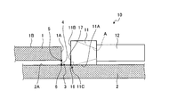
- the gap measuring device 10 measures a gap 4 between an upper plate (upper member) 1 and a lower plate (lower member) 2 which are disposed in a step-like manner.
- the upper plate 1 and the lower plate 2 are, for example, skin panels (skins) forming a cell structure of an aircraft fuselage, and are formed long (several m to 10 m) in the longitudinal direction (X direction in the figure) There is.
- the cell structure is formed in accordance with the following procedures (1) to (4).
- the upper plate 1 and the lower plate 2 are arranged such that the end portions of the upper plate 1 and the lower plate 2 overlap in the longitudinal direction.
- the upper plate 1 and the lower plate 2 are stacked in a step shape, and the step portion 3 is formed by the upper surface 2A of the lower plate 2 and the side end surface 1A and the upper surface 1B of the upper plate 1 Be done.
- the gap 4 between the upper plate 1 and the lower plate 2 in the step portion 3 is measured in the longitudinal direction.
- a predetermined reference value for example, 0.2 mm
- the upper plate 1 and the lower plate 2 are fastened (fastened).
- load is applied to the upper plate 1 and the lower plate 2 so that the gap 4 of that portion is within the reference value.
- the gap 4 is compressed (managed). Then, returning to the procedure of (2), if all the gaps 4 measured again are within the predetermined reference value (for example, 0.2 mm), the upper plate 1 and the lower plate 2 are fastened according to the procedure of (3).
- the clearance measurement device 10 of the present embodiment suitably measures the clearance 4 between the upper plate 1 and the lower plate 2 arranged in a step-like manner, and as shown in FIG.
- a light transmitting member 11 formed of a material (for example, acrylic resin), an imaging unit (for example, a fiberscope) 12 for capturing an image of the gap 4 through the light transmitting member 11, and the overall operation of the gap measuring device 10 are controlled.
- a control unit 13 a control unit 13.
- the imaging unit 12 is disposed on the opposite side to the side end surface 1A (the gap 4) of the upper plate 1 with the light transmitting member 11 interposed therebetween.
- the control unit 13 includes an image acquisition unit 14 that acquires image information of the clearance 4 captured by the imaging unit 12 and a clearance measurement unit 15 that measures the size of the clearance 4 based on the acquired image information.
- FIG. 2 is a side sectional view of the upper plate and the lower plate for explaining the gap measuring device and the gap
- FIG. 3 is a side of the upper plate and the lower plate showing the position of the gap measuring device when measuring the gap.
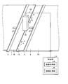
- FIG. FIG. 4 is a front view showing a second contact surface of the light transmitting member.
- the position of the point 6 which is the starting point of the gap 4.
- the imaging unit 12 is simply disposed to face the gap 4 and the gap 4 is imaged, the position of the point 6 can not be accurately identified on the captured image, and the gap 4 is accurately determined. It was difficult to measure the
- the light transmitting member 11 has a role of indicating the position of the point 6 which is the above-described calculation point. Specifically, the light transmitting member 11 is provided at a right angle to the first contact surface 11A that contacts the upper surface 2A of the lower plate 2 and the first contact surface 11A and contacts the side end surface 1A of the upper plate 1. And a second contact surface 11B that contacts.
- the side end surface 1A of the upper plate 1 usually inclines downward from the upper surface 1B of the upper plate 1 toward the upper surface 2A of the lower plate 2 in consideration of the flow resistance of the skin panel. For this reason, the second contact surface 11B of the light transmitting member 11 contacts at least the lower end portion 5 of the side end surface 1A.
- a broken line A shown in the light transmitting member 11 indicates the range of the image pickup area of the image pickup unit 12 and is set to a range larger than the second contact surface 11B of the light transmitting member 11. .
- the light transmitting member 11 is provided with a mark 16 indicating the position of the edge portion 11C on the edge portion 11C of the first contact surface 11A and the second contact surface 11B.
- the mark 16 is a color (for example, black) that reflects light and is coated with the edge portion 11C, and may have a configuration in which a part of the edge portion 11C is painted, or the first contact surface including the edge portion 11C. It is good also as composition painted up to 11A.
- the second contact surface 11B of the light transmitting member 11 is in contact with the side end surface 1A of the upper plate 1, the mark 16 provided on the edge portion 11C of the light transmitting member 11 Overlaps point 6 described above. Therefore, when the imaging unit 12 captures the gap 4 through the light transmitting member 11, the position of the mark 16 on the captured image is the point 6 described above, so the calculation point of the gap 4 can be easily specified. can do.
- the light transmitting member 11 extends from the mark 16 (edge portion 11C) in the height direction of the second contact surface 11B to the second contact surface 11B, and has a predetermined distance (for example, 0.1 mm).
- the scale 17 is set to.
- the scale 17 is a reference when measuring the size of the gap 4, and the predetermined length interval is stored in a storage unit (not shown) of the control unit 13.
- the scale 17 makes it possible to easily measure the actual size of the gap 4 from the size of the gap 4 on the image.
- the scale 17 is not necessarily provided as long as the size of the gap 4 can be measured.
- an image obtained by capturing a position set to a predetermined reference length from the mark 16 (edge portion 11C) is provided as a reference image
- the size of the gap 4 may be measured by comparing the reference image with the image obtained by capturing the gap 4.
- the control unit 13 causes the imaging unit 12 to image the gap 4 and causes the image acquisition unit 14 to acquire the imaged image information.
- the gap measuring unit 15 extracts the position of the point 6 which is the calculated point of the gap 4 from the position of the mark 16 and the position of the lower end portion 5 of the side end surface 1A. As described above, the distance between the point 6 and the lower end 5 is the size of the gap 4.
- the control unit 13 reads the length interval of the scale 17, and measures the size of the external distance (the gap 4) from the length interval and the distance between the point 6 and the lower end portion 5.
- the information of the measured gap 4 is stored, for example, in an external storage device or the like.
- the measurement process of the gap 4 described above is repeatedly performed over the longitudinal direction of the upper plate 1 and the lower plate 2 while changing the measurement point.
- the number and interval of the measurement points can be set as appropriate, but as the interval is shorter, it is possible to obtain measurement information with high accuracy.
- FIG. 5 is a schematic configuration view showing the clearance measurement device according to the second embodiment
- FIG. 6 is a schematic configuration view of a device main body of the clearance measurement device.
- the same components as those in the first embodiment described above are denoted by the same reference numerals and description thereof is omitted.
- the aggregates 8 and 9 are connected to the upper surface 1B of the upper plate 1 and the upper surface 2A of the lower plate 2 respectively, and the upper plate 1 and the lower plate 2 are supported by these aggregates 8 and 9 It is done.
- the aggregates 8 and 9 extend in the longitudinal direction (X direction in the figure) of the upper plate 1 and the lower plate 2 and are provided at predetermined intervals.
- the distance between the aggregates 8 and 9 is narrow in the step portion 3 in which the upper plate 1 and the lower plate 2 are stacked in a step-like manner.
- the light transmitting member 11 and the imaging unit 12 can not be arranged side by side on the upper surface 2A of the lower plate 2. I can not measure.
- the gap measuring device 20 according to the second embodiment measures the gap 4 accurately even in a narrow portion where the aggregates 8 and 9 are provided, for example.
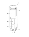
- the gap measuring device 20 includes an apparatus main body 21 disposed upright on the upper surface 2A of the lower plate 2 and a control unit 13. As shown in FIG. 6, the apparatus main body 21 is provided with an elongated rectangular cylindrical box 22 and an imaging unit (for example, a CCD image sensor or a CMOS image sensor) 23 in the box 22, and this imaging A magnifying lens (for example, a microscope lens, a macro lens, a telecentric lens, etc.) 24 for giving an enlarged image to the part 23 is accommodated.
- the optical axis S of the imaging unit 23 extends vertically to the vertical direction of the box 22, that is, vertically to the upper surface 2A of the lower plate 2.
- a CCD image sensor or a CMOS image sensor is used as the imaging unit 23, and a magnifying lens such as a microscope lens, a macro lens, or a telecentric lens is provided, as compared with a configuration using a fiberscope.
- the image with less distortion can be taken, and the measurement accuracy of the gap 4 can be improved.
- the device body 21 further includes an optical unit 25 disposed on the bottom surface 22A of the box 22.
- the optical unit 25 is integrally formed by including the light transmitting member 11 described above, a prism mirror (mirror unit) 26, and a holding pedestal 27.
- the prism mirror 26 is a triangular prism whose cross section is a right-angled isosceles triangle, and the mirror surface 28 is formed on the slope portion 26A.
- the prism mirror 26 is provided between the light transmitting member 11 and the imaging unit 23 and bends the optical axis S of the imaging unit 23 extending perpendicularly to the upper surface 2A of the lower plate 2 by 90 degrees, for example.
- the prism mirror 26 is formed in a triangular prism shape having a right-angled isosceles triangle in section, and the optical axis S is bent by 90 degrees, but parallel to the upper surface 2A of the lower plate 2 If it is made to reflect, the angle which bends optical axis S can be changed suitably.
- the holding pedestal 27 is a jig for holding the prism mirror 26 at a predetermined angular position, and is formed of a soft material (for example, Teflon (registered trademark) resin) whose hardness is lower than that of the upper plate 1 and the lower plate 2. Thereby, when the upper surface 2A of the lower plate 2 is in contact with the upper surface 2A, the upper surface 2A is prevented from being scratched.
- the holding pedestal 27 includes an abutting surface 27A that abuts on the upper surface 2A of the lower plate 2 and an inclined holding surface 27B that holds the prism mirror 26 opposite to the inclined surface 26A of the prism mirror 26. It has an equilateral triangle shape.
- the inclined holding surface 27B is formed in the same size as the inclined surface 26A of the prism mirror 26, when the prism mirror 26 is disposed on the inclined holding surface 27B, the lower end of the inclined surface 26A (mirror surface 28) of the prism mirror 26 is This corresponds to the height position of the upper surface 2A of the lower plate 2. Therefore, the gap 4 can be imaged by the imaging unit 23 from the height position of the upper surface 2A of the lower plate 2, and the gap 4 can be measured with high accuracy.
- the light transmitting member 11 is attached to the front surface 26 ⁇ / b> B facing the gap 4.
- the light transmitting member 11 is different from the first embodiment in that the thickness is reduced, but the other configuration is the same. Further, in the present embodiment, the thickness is formed thin in order to miniaturize the optical unit 25. However, it goes without saying that the thickness may be the same as that of the first embodiment.
- a prism mirror 26 is provided between the light transmitting member 11 and the imaging unit 23 to bend the optical axis of the imaging unit 23, for example, by 90 degrees, and the imaging unit 23 is disposed above the prism mirror 26.
- the device body 21 of the gap measuring device 20 can realize a structure extending vertically upward from the upper surface 2A of the lower plate 2. Therefore, for example, the gap 4 can be accurately measured even in a narrow portion where the aggregates 8 and 9 are provided.
- FIG. 7 is a schematic configuration view showing a gap management system provided with the gap measurement device according to the third embodiment
- FIG. 8 is a schematic configuration diagram of an apparatus main body of the gap measurement device.
- 9 is an external perspective view showing the optical unit and the lens fixing lens barrel
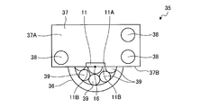
- FIG. 10 is a bottom view of the optical unit.
- the same components as those in the first and second embodiments described above are denoted by the same reference numerals, and descriptions thereof will be omitted.
- the clearance management system 100 includes the clearance measurement device 30 according to the third embodiment, and manages the measured clearance so that the size of the clearance is within a predetermined reference value.
- the clearance management system may be configured to include clearance measurement devices 10 and 20 according to the first and second embodiments, instead of the clearance measurement device 30 according to the third embodiment.
- the clearance measurement device 30 continuously measures the clearance 4 using a moving mechanism such as a robot.
- the gap measuring device 30 includes an apparatus main body 31 which is disposed upright on the upper surface 2A of the lower plate 2.
- the device body 31 is supported by, for example, a bracket 61 at the tip of a multi-axis articulated robot 60 (moving mechanism).
- the robot 60 operates under the control of the robot control unit 65, for example, by the operation of the operator.
- the gap measuring device 30 includes a monitoring camera 62 supported by the bracket 61, and a control unit 50 that controls the overall operation of the gap measuring device 30.
- the monitoring camera 62 captures the gap 4 measured by the apparatus body 31 and monitors the measurement state of the gap 4.
- the image taken by the surveillance camera 62 is output to the control unit 50 and displayed on the display of the operator room where the operator is present. The operator remotely controls the robot while viewing the image displayed on the display.
- the control unit 50 further includes a position information acquisition unit 51, a monitoring camera image acquisition unit 52, and a storage unit 53, in addition to the image acquisition unit 14 and the gap measurement unit 15 described above.
- the position information acquisition unit 51 acquires, from the robot control unit 65, the position of the gap 4 when measuring the gap 4, that is, the position information (coordinate information) of the device body 31 in the upper plate 1 and the lower plate 2.
- the surveillance camera image acquisition unit 52 acquires image information captured by the surveillance camera 62.
- the storage unit 53 stores information about the measured size of the gap 4 in association with the position information of the gap 4 acquired by the position information acquisition unit 51. In this case, by further linking and storing the image information of the monitoring camera 62, measurement and management of the gap 4 in the process of forming the cell structure can be performed with high accuracy.
- the apparatus main body 31 includes a cylindrical box 32 long in the vertical direction, and an imaging unit (for example, a CCD image sensor or a CMOS image sensor) 33 in the box 32, and the imaging unit A magnifying lens (for example, a microscope lens, a macro lens, a telecentric lens, etc.) 34 giving an image magnified to 33, and a lens fixing lens barrel 36 for fixing the magnifying lens 34 are accommodated.
- the optical axis S of the imaging unit 33 extends in the vertical direction of the box 32, that is, vertically to the upper surface 2A of the lower plate 2.
- the shape of the box 32 may be another shape such as a rectangular tube shape as long as the imaging portion 33, the magnifying lens 34 and the lens fixing lens barrel 36 can be accommodated.
- the apparatus body 31 further includes an optical unit 35 connected to the lens fixing barrel 36 and disposed at the lower end of the box 32.
- the optical unit 35 has the same configuration as the optical unit 25 described in the second embodiment, and is integrally formed by including the light transmitting member 11, the prism mirror (mirror unit) 26, and the holding pedestal 37.
- the light transmitting member 11 and the prism mirror 26 are the same as those in the second embodiment, and thus the description thereof is omitted.
- the holding pedestal 37 is formed in a rectangular parallelepiped shape as shown in FIG. 9 and holds the prism mirror 26 and the light transmitting member 11 at the center of the front surface 37 B of the holding pedestal 37.
- the first contact surface 11A is provided flush with the bottom surface 37A of the holding pedestal 37
- the second contact surface 11B is provided flush with the front surface 37B. Therefore, by bringing the bottom surface 37A of the holding pedestal 37 into contact with the upper surface 2A of the lower plate 2 and bringing the front surface 37B of the holding pedestal 37 into contact with the side end surface 1A of the upper plate 1, the first contact of the light transmitting member 11 is achieved.
- the surface 11A and the second abutment surface 11B abut on the upper surface 2A of the lower plate 2 and the side end surface 1A of the upper plate 1, respectively. Therefore, at point 6 (FIG. 6), the mark 16 of the edge portion 11C (FIG. 6) of the first contact surface 11A of the light transmitting member 11 and the second contact surface 11B becomes the calculation point of the gap 4. Since it overlaps with the position, the measurement of the gap 4 can be accurately performed.
- the holding pedestal 37 is provided with a touch sensor (contact detection unit) 38 for detecting contact on the bottom surface 37A and the front surface 37B of the holding pedestal 37, respectively.
- a touch sensor contact detection unit
- three or more touch sensors 38 are provided on the left and right of the light transmitting member 11.
- the bottom surface 37A of the holding pedestal 37 is two on one side (right side) with the light transmitting member 11 interposed therebetween. One is provided on the other (left side). Further, on the front surface 37B of the holding pedestal 37, one is provided on the other side (left side) across the light transmitting member 11.
- any method can be used as long as it can detect contact with the upper plate 1 and the lower plate 2.
- the touch sensors 38 are connected to the control unit 50, and the control unit 50 permits measurement of the gap 4 when all the touch sensors 38 detect a touch. Further, the operator may be notified that the measurement preparation has been completed by turning on a display lamp or the like. Further, as shown in FIG. 10, inside the lens fixing lens barrel 36, an irradiation lamp 39 for irradiating the front surface 37B side of the holding pedestal 37, that is, the light transmitting member 11 side is provided.
- the irradiation lamp 39 is, for example, an LED lamp, and gives the imaging unit 33 an amount of light capable of imaging.
- This measurement is performed by the robot control unit 65 moving the apparatus main body 31 and the robot 60 along the gap 4 by the operation of the operator.
- the apparatus main body 31 is disposed at a predetermined measurement start position. This position is a predetermined position.
- the control unit 50 determines whether or not all the touch sensors 38 detect a touch, and permits the start of the measurement if it is. Specifically, the display lamp provided in the operator's room is turned on and a measurement start operation instruction is received.
- the operator operates the measurement start button to start measurement.
- the apparatus body 31 and the robot 60 move at a predetermined speed along the gap 4.
- the image acquiring unit 14 acquires the image information of the gap 4 captured by the imaging unit 33, and measures the size of the gap 4 based on the image information.
- the position information acquisition unit 51 acquires the position information of the apparatus body 31 at the time of gap measurement from the robot control unit 65, and the information on the measured size of the gap 4 and the position of the gap 4 (device body 31). Information is linked and stored in the storage unit 53. This operation is continuously repeated over the longitudinal direction of the upper plate 1 and the lower plate 2.
- the clearance management system 100 applies a load to the upper plate 1 and the lower plate 2 after all the measurement is completed for the portion where the size of the clearance 4 is larger than the predetermined reference value, and the clearance 4 is the reference value. It can be compressed (managed) within the limits.
- the gap measuring devices 10, 20, and 30 are made of a translucent material, and are perpendicular to the first contact surface 11A that contacts the upper surface 2A of the lower plate 2 and the first contact surface 11A.
- a light transmitting member 11 provided and having a second contact surface 11B to be in contact with the side end surface 1A of the upper plate 1, and imaging units 12, 23, 33 for capturing an image of the gap 4 through the light transmitting member 11.
- the light transmission member 11 includes an edge portion 11C of the first contact surface 11A and the second contact surface 11B.
- the position of the mark 16 on the captured image is the gap In order to overlap with the starting point when measuring 4 2 a gap 4 of accurate and can be easily measured.
- the light transmitting member 11 is provided with the scale 17 provided at a predetermined distance from the edge portion 11C in the height direction of the second contact surface 11B, a gap with this scale 17 By comparing with 4, it is possible to easily measure the actual size of the gap 4 from the size of the gap 4 on the image.
- the mirror portion 26 that bends the optical axis S of the imaging units 23 and 33 and allows the light transmission member 11 to enter is provided between the light transmitting member 11 and the imaging units 23 and 33.
- the light transmitting member 11 and the imaging units 23 and 33 can be disposed compactly.
- the device bodies 21 and 31 of the gap measuring devices 20 and 30 can realize a structure extending vertically upward from the upper surface 2A of the lower plate 2. Therefore, for example, the gap 4 can be accurately measured even in a narrow portion where the aggregates 8 and 9 are provided.
- the touch sensor 38 detects that the first contact surface 11A and the second contact surface 11B are in contact with the upper surface 2A of the lower plate 2 and the side end surface 1A of the upper plate 1, respectively. Therefore, even when the apparatus main body 31 for measuring the gap 4 is mounted on the robot 60, it can be determined whether the apparatus main body 31 is at a suitable position for measurement. Therefore, the measurement of the gap 4 can be easily performed by remote control.
- the apparatus main body 31 is raised with the first contact surface 11A and the second contact surface 11B in contact with the upper surface 2A of the lower plate 2 and the side end surface 1A of the upper plate 1, respectively. Since the storage unit 53 is moved along the side end face 1A of the plate 1 to continuously measure the clearance 4 and store information on the measured size of the clearance 4 in association with the positional information of the clearance 4 The gap 4 between the upper plate 1 and the lower plate 2 arranged in a step-like manner can be measured accurately and quickly. Furthermore, since the size of the measured gap 4 is stored in the storage unit 53 together with the position information, the upper part of the gap 4 after the end of all the measurements for the part where the size of the gap 4 is larger than a predetermined reference value. A load can be applied to the plate 1 and the lower plate 2 so that the gap 4 can be compressed to be within the reference value.
- the gap 4 is continuously measured, and information regarding the size of the measured gap 4 is associated with the position information of the gap 4 and stored in the storage unit 53, but the storage unit 53 In addition to or in place of storage, marking may be performed to indicate the position of a portion where the size of the measured gap 4 exceeds a predetermined reference value. In this configuration, since the operator can visually determine the large position of the gap 4, the work of compressing the gap 4 can be easily advanced.
Landscapes
- Physics & Mathematics (AREA)
- General Physics & Mathematics (AREA)
- Engineering & Computer Science (AREA)
- Mechanical Engineering (AREA)
- General Engineering & Computer Science (AREA)
- Length Measuring Devices By Optical Means (AREA)
Abstract
L'objectif de la présente invention est de fournir un dispositif de mesure d'intervalle et un système de mesure d'intervalle avec lesquels il est possible pour un intervalle entre un élément supérieur et un élément inférieur qui se chevauchent l'un l'autre sous la forme d'une marche, d'être mesuré avec précision et facilement. Un dispositif de mesure d'intervalle (10) selon un mode de réalisation de la présente invention comprend : un élément translucide (11) qui est formé d'un matériau translucide et qui a une première surface de butée (11A) qui vient en butée contre une surface supérieure (2A) d'une plaque inférieure (2), et une seconde surface de butée (11B) qui est disposée de façon perpendiculaire à la première surface de butée (11A) et qui vient en butée contre une surface d'extrémité latérale (1A) d'une plaque supérieure (1); une unité de capture d'image qui capture une image d'un intervalle, à travers l'élément translucide (11); et une unité de mesure d'intervalle qui mesure l'intervalle sur la base d'informations d'image relatives à l'intervalle dont une image a été capturée. L'élément translucide (11) comprend, au niveau d'une partie de bord entre la première surface de butée (11A) et la seconde surface de butée (11B), une marque (16) indiquant la position de la partie de bord.
Priority Applications (3)
| Application Number | Priority Date | Filing Date | Title |
|---|---|---|---|
| EP16830289.1A EP3282221A4 (fr) | 2015-07-29 | 2016-07-11 | Dispositif de mesure d'intervalle et système de mesure d'intervalle |
| US15/577,667 US20180164092A1 (en) | 2015-07-29 | 2016-07-11 | Gap measuring device and gap management system |
| CN201680029098.0A CN107636417A (zh) | 2015-07-29 | 2016-07-11 | 间隙测量装置及间隙管理系统 |
Applications Claiming Priority (2)
| Application Number | Priority Date | Filing Date | Title |
|---|---|---|---|
| JP2015-149778 | 2015-07-29 | ||
| JP2015149778A JP2017032308A (ja) | 2015-07-29 | 2015-07-29 | 隙間計測装置、及び、隙間管理システム |
Publications (1)
| Publication Number | Publication Date |
|---|---|
| WO2017018184A1 true WO2017018184A1 (fr) | 2017-02-02 |
Family
ID=57884525
Family Applications (1)
| Application Number | Title | Priority Date | Filing Date |
|---|---|---|---|
| PCT/JP2016/070427 Ceased WO2017018184A1 (fr) | 2015-07-29 | 2016-07-11 | Dispositif de mesure d'intervalle et système de mesure d'intervalle |
Country Status (5)
| Country | Link |
|---|---|
| US (1) | US20180164092A1 (fr) |
| EP (1) | EP3282221A4 (fr) |
| JP (1) | JP2017032308A (fr) |
| CN (1) | CN107636417A (fr) |
| WO (1) | WO2017018184A1 (fr) |
Cited By (2)
| Publication number | Priority date | Publication date | Assignee | Title |
|---|---|---|---|---|
| CN106969720A (zh) * | 2017-04-01 | 2017-07-21 | 中国长江三峡集团公司 | 升船机安全机构螺纹副间隙集成化智能监测控制系统及方法 |
| WO2019052094A1 (fr) * | 2017-09-13 | 2019-03-21 | 深圳创怡兴实业有限公司 | Dispositif de détection de surface d'arbre de rouleau et procédé de détection de celui-ci |
Families Citing this family (2)
| Publication number | Priority date | Publication date | Assignee | Title |
|---|---|---|---|---|
| WO2022231948A1 (fr) * | 2021-04-26 | 2022-11-03 | Lam Research Corporation | Appareils pour mesurer un espace entre un support de substrat et un dispositif de distribution de gaz |
| FR3122492A1 (fr) * | 2021-04-29 | 2022-11-04 | Psa Automobiles Sa | Procédé de contrôle de conformité d’un assemblage de demi-cônes sur une queue de soupape de moteur |
Citations (7)
| Publication number | Priority date | Publication date | Assignee | Title |
|---|---|---|---|---|
| JPS5252579A (en) * | 1975-10-27 | 1977-04-27 | Canon Inc | Clearance adjusng method |
| JPS62108808U (fr) * | 1985-12-25 | 1987-07-11 | ||
| JPH0569133A (ja) * | 1991-09-10 | 1993-03-23 | Hitachi Ltd | 加工位置検出装置および加工位置検出方法 |
| JPH07140042A (ja) * | 1993-11-16 | 1995-06-02 | Hitachi Electron Eng Co Ltd | マスク板とガラス基板のギャップ測定光学系 |
| JPH0972832A (ja) * | 1995-09-06 | 1997-03-18 | Ando Corp | 採取式堆積厚測定器 |
| JP2007256162A (ja) * | 2006-03-24 | 2007-10-04 | Honda Motor Co Ltd | バルブシート隙間計測装置 |
| JP3168056U (ja) * | 2010-12-20 | 2011-06-02 | クツワ株式会社 | 計測用文房具 |
Family Cites Families (11)
| Publication number | Priority date | Publication date | Assignee | Title |
|---|---|---|---|---|
| US4700045A (en) * | 1985-04-30 | 1987-10-13 | Chesapeake Laser Systems, Inc. | Seam tracking system with acousto-optical scanner |
| JP3363715B2 (ja) * | 1996-08-29 | 2003-01-08 | 松下電器産業株式会社 | 溶接線検出方法と装置 |
| JPH10272566A (ja) * | 1997-03-28 | 1998-10-13 | Nkk Corp | 隅肉継手開先のルートギャップ検出方法 |
| US5957366A (en) * | 1997-10-21 | 1999-09-28 | Ameron International Corporation | Helically formed welded pipe and diameter control |
| WO2002010721A2 (fr) * | 2000-08-01 | 2002-02-07 | Board Of Regents, The University Of Texas System | Procede de detection haute precision d'un intervalle et d'une orientation entre un modele transparent et un substrat, utilise en lithographie par empreinte |
| WO2003063231A1 (fr) * | 2002-01-23 | 2003-07-31 | Matsushita Electric Industrial Co., Ltd. | Element de boitier et son procede de fabrication |
| US7525667B2 (en) * | 2004-05-24 | 2009-04-28 | International Electronic Machines Corp. | Portable electronic measurement |
| JP4897006B2 (ja) * | 2008-03-04 | 2012-03-14 | エーエスエムエル ネザーランズ ビー.ブイ. | アラインメントマークを設ける方法、デバイス製造方法及びリソグラフィ装置 |
| CN101825440B (zh) * | 2009-03-03 | 2012-07-18 | 鸿富锦精密工业(深圳)有限公司 | 产品零件间隙检测系统及方法 |
| JP5912666B2 (ja) * | 2012-02-29 | 2016-04-27 | 中央電子株式会社 | 計測装置及びその処理方法 |
| CN103925884B (zh) * | 2013-01-14 | 2017-04-26 | 上海核工程研究设计院 | 一种径向支承键装配间隙自动测量装置 |
-
2015
- 2015-07-29 JP JP2015149778A patent/JP2017032308A/ja active Pending
-
2016
- 2016-07-11 EP EP16830289.1A patent/EP3282221A4/fr not_active Withdrawn
- 2016-07-11 WO PCT/JP2016/070427 patent/WO2017018184A1/fr not_active Ceased
- 2016-07-11 CN CN201680029098.0A patent/CN107636417A/zh not_active Withdrawn
- 2016-07-11 US US15/577,667 patent/US20180164092A1/en not_active Abandoned
Patent Citations (7)
| Publication number | Priority date | Publication date | Assignee | Title |
|---|---|---|---|---|
| JPS5252579A (en) * | 1975-10-27 | 1977-04-27 | Canon Inc | Clearance adjusng method |
| JPS62108808U (fr) * | 1985-12-25 | 1987-07-11 | ||
| JPH0569133A (ja) * | 1991-09-10 | 1993-03-23 | Hitachi Ltd | 加工位置検出装置および加工位置検出方法 |
| JPH07140042A (ja) * | 1993-11-16 | 1995-06-02 | Hitachi Electron Eng Co Ltd | マスク板とガラス基板のギャップ測定光学系 |
| JPH0972832A (ja) * | 1995-09-06 | 1997-03-18 | Ando Corp | 採取式堆積厚測定器 |
| JP2007256162A (ja) * | 2006-03-24 | 2007-10-04 | Honda Motor Co Ltd | バルブシート隙間計測装置 |
| JP3168056U (ja) * | 2010-12-20 | 2011-06-02 | クツワ株式会社 | 計測用文房具 |
Non-Patent Citations (1)
| Title |
|---|
| See also references of EP3282221A4 * |
Cited By (3)
| Publication number | Priority date | Publication date | Assignee | Title |
|---|---|---|---|---|
| CN106969720A (zh) * | 2017-04-01 | 2017-07-21 | 中国长江三峡集团公司 | 升船机安全机构螺纹副间隙集成化智能监测控制系统及方法 |
| CN106969720B (zh) * | 2017-04-01 | 2023-01-06 | 中国长江三峡集团公司 | 升船机安全机构螺纹副间隙集成化智能监测控制系统及方法 |
| WO2019052094A1 (fr) * | 2017-09-13 | 2019-03-21 | 深圳创怡兴实业有限公司 | Dispositif de détection de surface d'arbre de rouleau et procédé de détection de celui-ci |
Also Published As
| Publication number | Publication date |
|---|---|
| JP2017032308A (ja) | 2017-02-09 |
| EP3282221A4 (fr) | 2018-04-11 |
| EP3282221A1 (fr) | 2018-02-14 |
| CN107636417A (zh) | 2018-01-26 |
| US20180164092A1 (en) | 2018-06-14 |
Similar Documents
| Publication | Publication Date | Title |
|---|---|---|
| EP3619498B1 (fr) | Scanner de triangulation ayant une géométrie plate et projetant des points non codés | |
| TWI427286B (zh) | 用於檢測玻璃板之裝置及方法 | |
| WO2017018184A1 (fr) | Dispositif de mesure d'intervalle et système de mesure d'intervalle | |
| TWI348018B (en) | Method and system for measuring the shape of a reflective surface, and method for calibrating the system | |
| KR101652355B1 (ko) | 광학적 웨이퍼 검사 장치 | |
| CN103733052B (zh) | 转子叶片的诊断 | |
| KR101238220B1 (ko) | 크랙모니터링시스템 | |
| JP2015230393A (ja) | 撮像装置の制御方法および撮像システム | |
| JP4317743B2 (ja) | 光学式圧子接触面のその場定量に基づく力学特性計測法及びその試験装置 | |
| CN109283184A (zh) | 一种基于光谱共焦传感器的表面疵病测量方法 | |
| KR20230028385A (ko) | 비디오 익스텐소미터를 위한 두께 보정 시스템 및 방법 | |
| CN104180772B (zh) | 一种视觉检测装置 | |
| KR20240012553A (ko) | 비디오 익스텐소미터를 위한 오차 보정 시스템 및 오차 보정 방법 | |
| US10162189B2 (en) | Device, system and method for the visual alignment of a pipettor tip and a reference point marker | |
| CN204027528U (zh) | 一种视觉检测装置 | |
| JP2011138096A (ja) | 測定顕微鏡 | |
| CN121095128A (zh) | 用于视频引伸计系统的亮度和对比度校正以及方法 | |
| CN105157615A (zh) | 一种用于真空的三维形貌测量系统 | |
| TWM477571U (zh) | 一種用以擷取一物件影像的擷取裝置以及影像檢測裝置 | |
| TW201534903A (zh) | 物件檢測方法及裝置 | |
| CN105547659B (zh) | 检测数字切片病理扫描仪的平台倾角的系统及方法 | |
| CN100529744C (zh) | 光学检测装置和检测方法 | |
| JP2007139596A (ja) | 可搬式運動計測システムおよび運動計測方法 | |
| KR20210031557A (ko) | 특성 측정 장치 및 특성 측정 방법 | |
| CN208606989U (zh) | 光学检测装置 |
Legal Events
| Date | Code | Title | Description |
|---|---|---|---|
| 121 | Ep: the epo has been informed by wipo that ep was designated in this application |
Ref document number: 16830289 Country of ref document: EP Kind code of ref document: A1 |
|
| WWE | Wipo information: entry into national phase |
Ref document number: 15577667 Country of ref document: US |
|
| NENP | Non-entry into the national phase |
Ref country code: DE |