WO2017018235A1 - Stratifié textile, procédé de fabrication de stratifié textile et dispositif de fabrication de stratifié textile - Google Patents
Stratifié textile, procédé de fabrication de stratifié textile et dispositif de fabrication de stratifié textile Download PDFInfo
- Publication number
- WO2017018235A1 WO2017018235A1 PCT/JP2016/070895 JP2016070895W WO2017018235A1 WO 2017018235 A1 WO2017018235 A1 WO 2017018235A1 JP 2016070895 W JP2016070895 W JP 2016070895W WO 2017018235 A1 WO2017018235 A1 WO 2017018235A1
- Authority
- WO
- WIPO (PCT)
- Prior art keywords
- twist
- unidirectional
- twisted
- yarn
- fabric laminate
- Prior art date
- Legal status (The legal status is an assumption and is not a legal conclusion. Google has not performed a legal analysis and makes no representation as to the accuracy of the status listed.)
- Ceased
Links
Images






Classifications
-
- B—PERFORMING OPERATIONS; TRANSPORTING
- B32—LAYERED PRODUCTS
- B32B—LAYERED PRODUCTS, i.e. PRODUCTS BUILT-UP OF STRATA OF FLAT OR NON-FLAT, e.g. CELLULAR OR HONEYCOMB, FORM
- B32B5/00—Layered products characterised by the non- homogeneity or physical structure, i.e. comprising a fibrous, filamentary, particulate or foam layer; Layered products characterised by having a layer differing constitutionally or physically in different parts
- B32B5/22—Layered products characterised by the non- homogeneity or physical structure, i.e. comprising a fibrous, filamentary, particulate or foam layer; Layered products characterised by having a layer differing constitutionally or physically in different parts characterised by the presence of two or more layers which are next to each other and are fibrous, filamentary, formed of particles or foamed
- B32B5/24—Layered products characterised by the non- homogeneity or physical structure, i.e. comprising a fibrous, filamentary, particulate or foam layer; Layered products characterised by having a layer differing constitutionally or physically in different parts characterised by the presence of two or more layers which are next to each other and are fibrous, filamentary, formed of particles or foamed one layer being a fibrous or filamentary layer
- B32B5/26—Layered products characterised by the non- homogeneity or physical structure, i.e. comprising a fibrous, filamentary, particulate or foam layer; Layered products characterised by having a layer differing constitutionally or physically in different parts characterised by the presence of two or more layers which are next to each other and are fibrous, filamentary, formed of particles or foamed one layer being a fibrous or filamentary layer another layer next to it also being fibrous or filamentary
-
- B—PERFORMING OPERATIONS; TRANSPORTING
- B32—LAYERED PRODUCTS
- B32B—LAYERED PRODUCTS, i.e. PRODUCTS BUILT-UP OF STRATA OF FLAT OR NON-FLAT, e.g. CELLULAR OR HONEYCOMB, FORM
- B32B1/00—Layered products having a non-planar shape
-
- B—PERFORMING OPERATIONS; TRANSPORTING
- B32—LAYERED PRODUCTS
- B32B—LAYERED PRODUCTS, i.e. PRODUCTS BUILT-UP OF STRATA OF FLAT OR NON-FLAT, e.g. CELLULAR OR HONEYCOMB, FORM
- B32B37/00—Methods or apparatus for laminating, e.g. by curing or by ultrasonic bonding
- B32B37/0046—Methods or apparatus for laminating, e.g. by curing or by ultrasonic bonding characterised by constructional aspects of the apparatus
-
- B—PERFORMING OPERATIONS; TRANSPORTING
- B32—LAYERED PRODUCTS
- B32B—LAYERED PRODUCTS, i.e. PRODUCTS BUILT-UP OF STRATA OF FLAT OR NON-FLAT, e.g. CELLULAR OR HONEYCOMB, FORM
- B32B37/00—Methods or apparatus for laminating, e.g. by curing or by ultrasonic bonding
- B32B37/14—Methods or apparatus for laminating, e.g. by curing or by ultrasonic bonding characterised by the properties of the layers
- B32B37/16—Methods or apparatus for laminating, e.g. by curing or by ultrasonic bonding characterised by the properties of the layers with all layers existing as coherent layers before laminating
- B32B37/18—Methods or apparatus for laminating, e.g. by curing or by ultrasonic bonding characterised by the properties of the layers with all layers existing as coherent layers before laminating involving the assembly of discrete sheets or panels only
-
- B—PERFORMING OPERATIONS; TRANSPORTING
- B32—LAYERED PRODUCTS
- B32B—LAYERED PRODUCTS, i.e. PRODUCTS BUILT-UP OF STRATA OF FLAT OR NON-FLAT, e.g. CELLULAR OR HONEYCOMB, FORM
- B32B5/00—Layered products characterised by the non- homogeneity or physical structure, i.e. comprising a fibrous, filamentary, particulate or foam layer; Layered products characterised by having a layer differing constitutionally or physically in different parts
- B32B5/02—Layered products characterised by the non- homogeneity or physical structure, i.e. comprising a fibrous, filamentary, particulate or foam layer; Layered products characterised by having a layer differing constitutionally or physically in different parts characterised by structural features of a fibrous or filamentary layer
- B32B5/022—Non-woven fabric
-
- B—PERFORMING OPERATIONS; TRANSPORTING
- B32—LAYERED PRODUCTS
- B32B—LAYERED PRODUCTS, i.e. PRODUCTS BUILT-UP OF STRATA OF FLAT OR NON-FLAT, e.g. CELLULAR OR HONEYCOMB, FORM
- B32B5/00—Layered products characterised by the non- homogeneity or physical structure, i.e. comprising a fibrous, filamentary, particulate or foam layer; Layered products characterised by having a layer differing constitutionally or physically in different parts
- B32B5/02—Layered products characterised by the non- homogeneity or physical structure, i.e. comprising a fibrous, filamentary, particulate or foam layer; Layered products characterised by having a layer differing constitutionally or physically in different parts characterised by structural features of a fibrous or filamentary layer
- B32B5/06—Layered products characterised by the non- homogeneity or physical structure, i.e. comprising a fibrous, filamentary, particulate or foam layer; Layered products characterised by having a layer differing constitutionally or physically in different parts characterised by structural features of a fibrous or filamentary layer characterised by a fibrous or filamentary layer mechanically connected, e.g. by needling to another layer, e.g. of fibres, of paper
-
- B—PERFORMING OPERATIONS; TRANSPORTING
- B32—LAYERED PRODUCTS
- B32B—LAYERED PRODUCTS, i.e. PRODUCTS BUILT-UP OF STRATA OF FLAT OR NON-FLAT, e.g. CELLULAR OR HONEYCOMB, FORM
- B32B5/00—Layered products characterised by the non- homogeneity or physical structure, i.e. comprising a fibrous, filamentary, particulate or foam layer; Layered products characterised by having a layer differing constitutionally or physically in different parts
- B32B5/02—Layered products characterised by the non- homogeneity or physical structure, i.e. comprising a fibrous, filamentary, particulate or foam layer; Layered products characterised by having a layer differing constitutionally or physically in different parts characterised by structural features of a fibrous or filamentary layer
- B32B5/08—Layered products characterised by the non- homogeneity or physical structure, i.e. comprising a fibrous, filamentary, particulate or foam layer; Layered products characterised by having a layer differing constitutionally or physically in different parts characterised by structural features of a fibrous or filamentary layer the fibres or filaments of a layer being of different substances, e.g. conjugate fibres, mixture of different fibres
-
- B—PERFORMING OPERATIONS; TRANSPORTING
- B32—LAYERED PRODUCTS
- B32B—LAYERED PRODUCTS, i.e. PRODUCTS BUILT-UP OF STRATA OF FLAT OR NON-FLAT, e.g. CELLULAR OR HONEYCOMB, FORM
- B32B5/00—Layered products characterised by the non- homogeneity or physical structure, i.e. comprising a fibrous, filamentary, particulate or foam layer; Layered products characterised by having a layer differing constitutionally or physically in different parts
- B32B5/02—Layered products characterised by the non- homogeneity or physical structure, i.e. comprising a fibrous, filamentary, particulate or foam layer; Layered products characterised by having a layer differing constitutionally or physically in different parts characterised by structural features of a fibrous or filamentary layer
- B32B5/12—Layered products characterised by the non- homogeneity or physical structure, i.e. comprising a fibrous, filamentary, particulate or foam layer; Layered products characterised by having a layer differing constitutionally or physically in different parts characterised by structural features of a fibrous or filamentary layer characterised by the relative arrangement of fibres or filaments of different layers, e.g. the fibres or filaments being parallel or perpendicular to each other
-
- B—PERFORMING OPERATIONS; TRANSPORTING
- B32—LAYERED PRODUCTS
- B32B—LAYERED PRODUCTS, i.e. PRODUCTS BUILT-UP OF STRATA OF FLAT OR NON-FLAT, e.g. CELLULAR OR HONEYCOMB, FORM
- B32B7/00—Layered products characterised by the relation between layers; Layered products characterised by the relative orientation of features between layers, or by the relative values of a measurable parameter between layers, i.e. products comprising layers having different physical, chemical or physicochemical properties; Layered products characterised by the interconnection of layers
- B32B7/04—Interconnection of layers
- B32B7/05—Interconnection of layers the layers not being connected over the whole surface, e.g. discontinuous connection or patterned connection
-
- B—PERFORMING OPERATIONS; TRANSPORTING
- B32—LAYERED PRODUCTS
- B32B—LAYERED PRODUCTS, i.e. PRODUCTS BUILT-UP OF STRATA OF FLAT OR NON-FLAT, e.g. CELLULAR OR HONEYCOMB, FORM
- B32B2262/00—Composition or structural features of fibres which form a fibrous or filamentary layer or are present as additives
- B32B2262/02—Synthetic macromolecular fibres
- B32B2262/0261—Polyamide fibres
-
- B—PERFORMING OPERATIONS; TRANSPORTING
- B32—LAYERED PRODUCTS
- B32B—LAYERED PRODUCTS, i.e. PRODUCTS BUILT-UP OF STRATA OF FLAT OR NON-FLAT, e.g. CELLULAR OR HONEYCOMB, FORM
- B32B2262/00—Composition or structural features of fibres which form a fibrous or filamentary layer or are present as additives
- B32B2262/10—Inorganic fibres
- B32B2262/106—Carbon fibres, e.g. graphite fibres
Definitions
- the present invention relates to a woven fabric laminate in which a plurality of unidirectional fabrics in which a plurality of yarns are arranged in a uniaxial orientation are stacked, and a plurality of unidirectional fabrics are bonded in the stacking direction by binding yarns, and a method for manufacturing a woven fabric laminate And an apparatus for manufacturing a woven fabric laminate.
- Fiber reinforced composite materials are widely used as lightweight structural materials.
- a reinforced base material for composite materials there is a woven structure using a three-dimensional woven fabric.
- a woven fabric structure having a twisted structure is required instead of a simple flat plate shape.
- the woven structure having a twisted structure examples include a three-dimensional fiber structure disclosed in Patent Document 1.
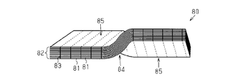
- the three-dimensional fiber structure 80 of Patent Document 1 includes a biaxially oriented laminated fiber layer 82 formed by laminating a fiber layer 81 made of continuous fibers using a thickness direction thread 83. It is configured by combining.
- the biaxial orientation in the three-dimensional fiber structure 80 means the longitudinal direction and the short direction of the three-dimensional fiber structure 80.
- the three-dimensional fiber structure 80 includes a bent portion 84 and a plate-like portion 85 that extends from both sides of the bent portion 84 in the longitudinal direction of the three-dimensional fiber structure 80.
- the three-dimensional fiber structure 80 has a propeller shape in which a plate-like portion 85 is twisted around a bent portion 84.
- the three-dimensional fiber structure 80 is twisted around a twist axis extending in the longitudinal direction.
- the three-dimensional fiber structure 80 disclosed in Patent Document 1 is manufactured by twisting a primary structure in which a plurality of fiber layers 81 are bonded in advance with a thickness direction thread 83.
- the portion that becomes the plate-like portion 85 of each fiber layer 81 is joined by the thickness direction thread 83, but the portion that becomes the bent portion 84 is not joined by the thickness direction thread 83.
- the continuous fibers of the plate-like portion 85 are less likely to follow the twist of the primary structure due to the fiber layers 81 being joined by the thickness direction threads 83. Therefore, the continuous fiber of the plate-like portion 85 bends or curves into an unnatural shape that does not follow the twist of the primary structure. For this reason, the straightness of the continuous fibers is not maintained, and the strength of the plate-like portion 85 is lowered.
- An object of the present invention is to provide a fabric laminate, a method for producing a fabric laminate, and a fabric laminate production apparatus in which the straightness of the yarn is maintained and the strength does not decrease even if the twisted structure is provided. It is in.
- a plurality of unidirectional fabrics in which a plurality of yarns are arranged in a uniaxial orientation are stacked, and a plurality of unidirectional fabrics are stacked with a binding yarn.
- a directionally bonded fabric laminate is provided.
- the woven fabric laminate is twisted about a twist axis extending linearly in a predetermined direction, and at least one unidirectional fabric thread of the plurality of unidirectional fabrics is oriented so as to intersect the twist axis.
- the woven fabric laminate includes a pair of side edges located at both ends in the axial direction of the twist axis and a twist edge connecting the pair of side edges. When viewed from the direction orthogonal to the twist axis, the yarn of the unidirectional fabric that intersects the twist axis extends linearly from the twist axis toward the twist edge.
- a plurality of unidirectional fabrics in which a plurality of yarns are arranged in a uniaxial orientation are stacked, and a plurality of unidirectional fabrics are stacked with a binding yarn.
- a method for producing a directionally bonded fabric laminate is provided. According to this manufacturing method, a plurality of unidirectional fabrics are laminated such that at least one of the unidirectional fabrics is oriented so that the yarn of at least one unidirectional fabric intersects the twist axis. The fabric is twisted about a twisting axis extending linearly in a predetermined direction, and then a plurality of twisted unidirectional fabrics are bonded in the stacking direction by a binding yarn.
- a plurality of unidirectional fabrics in which a plurality of yarns are arranged in a uniaxial orientation are stacked, and a plurality of unidirectional fabrics are stacked with a binding yarn.
- An apparatus for manufacturing a woven fabric laminate is provided that is twisted about a twist axis that is coupled in a direction and extends linearly in a predetermined direction.
- the manufacturing apparatus includes a plurality of first laying frames and second laminating frames sandwiched in a twisted state while laminating a plurality of unidirectional fabrics, and a plurality of first laminating frames and second laminating frames. And a fixing member that fixes the unidirectional fabric in a sandwiched state.
- a plurality of back plates that support a plurality of unidirectional fabrics can be attached to and detached from the first laminating frame, and a plurality of unidirectional fabrics that press the plurality of unidirectional fabrics against the back plate are attached to the second laminating frame.
- the press plate is removable.
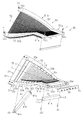
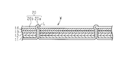
- the perspective view which shows the textiles laminated body which concerns on one Embodiment of this invention The longitudinal cross-sectional view of a textile laminated body.
- the disassembled perspective view of the manufacturing apparatus of a textiles laminated body The perspective view of the manufacturing apparatus of a textiles laminated body.
- the fragmentary perspective view explaining the manufacturing method of a textiles laminated body The perspective view which shows typically the fabric laminated body of another example.
- Sectional drawing which shows the textile fabric laminated body of another example.
- the fiber reinforced composite material M is formed by impregnating a matrix resin Ma into a woven fabric laminate W as a reinforced base material.
- the woven fabric W is formed by stacking four fiber layers 11-14.
- the fiber layer constituting the lowermost layer of the woven fabric laminate W is referred to as a first fiber layer 11
- the fiber layer stacked on the first fiber layer 11 is referred to as a second fiber layer 12.
- the fiber layer stacked on the second fiber layer 12 is defined as a third fiber layer 13
- the fiber layer stacked on the third fiber layer 13 and constituting the uppermost layer of the woven laminate W is a fourth fiber.
- Layer 14 is assumed.
- the direction in which the first to fourth fiber layers 11 to 14 are stacked is defined as a stacking direction.
- the stacking direction of the first to fourth fiber layers 11 to 14 is the thickness direction, and the dimension along the thickness direction is the thickness of each fiber layer 11 to 14.
- the first to fourth fiber layers 11 to 14 have a rectangular surface in plan view.
- a direction along the long side of the surface of the first to fourth fiber layers 11 to 14 is defined as a longitudinal direction
- a direction along the short side is defined as a short direction.
- each of the first to fourth fiber layers 11 to 14 has a plurality of warp yarns 10a arranged in one direction so as to be uniaxially oriented, and the plurality of warp yarns 10a are joined by weft yarns 10b. It is composed of.
- the warp yarn 10a is made of, for example, carbon fiber, and the weft yarn 10b is made of nylon yarn.
- the weft yarn 10b is welded to the warp yarn 10a. Thereby, the uniaxial orientation of the warp 10a is maintained.
- the orientation angle of the warp 10a in the first fiber layer 11 is 0 degree.
- the warp yarns 10 a are arranged in a state extending in the longitudinal direction of the first fiber layer 11.
- the orientation angle of the warp yarn 10a in the second fiber layer 12 is 45 degrees.
- the warp yarns 10 a are aligned in a state inclined by 45 degrees with respect to the longitudinal direction of the second fiber layer 12.
- the orientation angle of the warp 10a in the third fiber layer 13 is -45 degrees.
- the warp yarns 10 a are aligned in a state inclined by ⁇ 45 degrees with respect to the longitudinal direction of the third fiber layer 13.
- the orientation angle of the warp 10a in the fourth fiber layer 14 is 90 degrees.
- the warp 10a is arranged in a state extending in the short direction of the fourth fiber layer 14. Therefore, based on the orientation angle of the warp yarn 10a in the first to fourth fiber layers 11 to 14, the fabric laminate W has pseudo-isotropic properties in four directions.
- the first to fourth fiber layers 11 to 14 are bonded in the stacking direction by a bonding structure 20 having a bonding thread 20a extending in the thickness direction thereof.
- the coupling structure 20 is composed of a coupling thread 20a and a retaining thread 20b.
- the plurality of binding yarns 20a are arranged on the surface of the first fiber layer 11 so as to extend in the longitudinal direction.
- Each of the binding yarns 20a is inserted into the woven fabric laminate W from the outside at a predetermined pitch. Further, each binding yarn 20a protrudes from the outer surface of the fourth fiber layer 14 of the woven fabric laminate W, and is then folded back in a loop shape.
- Each binding yarn 20a extends in the stacking direction orthogonal to the surfaces of the first to fourth fiber layers 11-14.
- a plurality of retaining threads 20b are arranged on the surface of the fourth fiber layer 14 so as to extend in the short direction.
- the retaining threads 20b are arranged at intervals in the longitudinal direction of the fourth fiber layer 14.
- the retaining yarns 20b are arranged so that the binding yarns 20a are not removed from the fabric laminate W by being inserted into the loop L of the binding yarns 20a.
- the fabric laminate W includes a twist region R1 twisted about the twist axis 21 and a flat plate-like region R2 that is continuous and flat with the twist region R1.
- the twist axis 21 passes through the center point of the fabric laminate W in the short direction.
- the twist axis line 21 extends linearly along the longitudinal direction and has straightness.
- the twist axis 21 passes through the twist region R1 and the flat region R2.
- the short edge part of the textile laminated body W located in the both ends of the axial direction of the twist axis 21 is set as the side edge part 22.
- a long edge portion of the fabric laminate W that connects corresponding end portions of the two side edge portions 22 is referred to as a twisted edge portion 23.
- the warp yarn 10 a of the first fiber layer 11 extends linearly in a state parallel to the twist axis 21.
- the warp yarn 10 a of the second fiber layer 12 extends linearly from the twist axis 21 toward each twist edge 23 in a state inclined by 45 degrees with respect to the twist axis 21.
- the warp yarn 10 a of the third fiber layer 13 extends linearly from the twist axis 21 toward each twist edge 23 in a state inclined by ⁇ 45 degrees with respect to the twist axis 21.
- the warp yarn 10 a of the fourth fiber layer 14 extends linearly from the twist axis 21 toward each twist edge 23 in a state orthogonal to the twist axis 21.
- the warps 10a of the second to fourth fiber layers 12 to 14 are twisted from the twist axis 21 in each of the twist region R1 and the flat region R2. It extends linearly toward the edge 23.
- the manufacturing apparatus 30 includes a first laminating frame 31 and a second laminating frame that hold the first to fourth fiber layers 11 to 14 in a twisted state while being laminated. 51.
- the manufacturing apparatus 30 further includes a fixing member 71 that fixes the first to fourth fiber layers 11 to 14 between the first stacking frame 31 and the second stacking frame 51.
- the fixing member 71 is a bolt.
- the first stacking frame 31 is made of metal.
- the first stacking frame 31 includes a rectangular base plate-like first base plate 32a and second base plate 32b located at both ends in the longitudinal direction.
- the first stacking frame 31 further includes a pair of support plates 33 that connect corresponding ends of the first base plate 32a and the second base plate 32b.
- the first stacking frame 31 is formed in a rectangular frame shape by integrating the first base plate 32a, the second base plate 32b, and the support plate 33.
- the first stacking frame 31 has a flat portion 31a in the vicinity of the first base plate 32a.
- the first laminating frame 31 has a twisted portion 31b that is twisted about the twisted axis 38 between the flat portion 31a and the second base plate 32b.
- the twist axis 38 passes straight in the longitudinal direction while passing through the center point in the short direction of the twist portion 31b.
- the first stacking frame 31 further includes a shaft mounting plate 35 integrated with the first base plate 32a.
- the shaft attachment plate 35 includes a rotation shaft 36 that is positioned coaxially with an extension line of the twist axis 38.
- the part which comprises the flat part 31a of each support plate 33 is a rectangular parallelepiped shape.
- the part which comprises the twist part 31b of each support plate 33 is twisted moderately.
- the distance between the pair of support plates 33 is constant along the longitudinal direction of the support plate 33.
- the support plate 33 has two side surfaces that face each other in the thickness direction.
- One side surface of the support plate 33 is an attachment surface 33a, and the other side surface is a support surface 33b.
- the support plate 33 includes a plurality of screw holes 33c that are recessed from the mounting surface 33a.
- the plurality of screw holes 33 c are arranged at equal intervals in the longitudinal direction of the support plate 33.
- the support plate 33 includes fixing screw holes 33d at both ends in the longitudinal direction.
- the first stacking frame 31 includes a plurality of back plates 41 a and 41 b attached to the support plate 33.
- the plurality of back plates 41a and 41b support the first to fourth fiber layers 11 to 14.
- the back plates 41a and 41b are made of metal.
- the back plate includes a flat portion back plate 41a attached to the flat portion 31a and a twist portion back plate 41b attached to the twist portion 31b.
- the flat portion back plate 41a is a rectangular plate.
- the back plate 41b for the twisted portion is twisted in accordance with the twisting degree of the pair of support plates 33 with the rectangular plate being centered on the middle point in the longitudinal direction.
- Each back plate 41a, 41b has an insertion hole 41c that penetrates both ends in the longitudinal direction in the thickness direction.
- Bolts 42 can pass through the insertion holes 41c.
- the bolt 42 can be screwed into the screw hole 33 c of the support plate 33.
- stepped portions 43 that are thinner than other portions are provided.
- a support portion 44 is provided between both step portions 43 of the back plates 41a and 41b.
- the depth from the surface of the support portion 44 to the stepped portion 43 is the same as the thickness of the support plate 33. Further, the length of the support portion 44 is slightly shorter than the distance between the opposing inner side surfaces of the pair of support plates 33.
- the step portion 43 is brought into contact with the flat portion 31a of the support plate 33, and the support portion 44 is disposed between the adjacent support plates 33. Further, in the back plate 41 b for the twisted portion, the stepped portion 43 is brought into contact with the twisted portion 31 b of the support plate 33, and the support portion 44 is disposed between the adjacent support plates 33.
- the bolts 42 are inserted into the insertion holes 41 c and screwed into the screw holes 33 c of the support plate 33, whereby the back plates 41 a and 41 b are attached to the support plate 33.
- the back plates 41 a and 41 b can be detached from the support plate 33 and detached from the first laminating frame 31.
- the second stacking frame 51 is made of metal.
- the second laminating frame 51 has a flat portion 51a in the vicinity of one end portion of both end portions in the longitudinal direction.
- the second laminating frame 51 further includes a twisted portion 51b that is twisted about the twist axis 58 between the flat portion 51a and the other end.
- the twisting axis 58 goes straight in the longitudinal direction while passing through the center point in the short direction of the twisted portion 51b.
- the second stacking frame 51 has a pair of mounting plates 52.
- the part which comprises the flat part 51a of each attachment plate 52 is a rectangular parallelepiped.
- the part which comprises the twist part 51b of each attachment plate 52 is twisted moderately.
- the mounting plate 52 has two side surfaces that face each other in the thickness direction.
- One side surface of the mounting plate 52 is a plate mounting surface 52a.
- the mounting plate 52 includes a plurality of mounting grooves 52b that are recessed from the plate mounting surface 52a.
- the plurality of mounting grooves 52 b are arranged at equal intervals in the longitudinal direction of the mounting plate 52.
- each mounting plate 52 has a through hole 52c that penetrates both ends in the longitudinal direction in the thickness direction.
- a fixing member 71 for fixing the second stacking frame 51 to the first stacking frame 31 can pass through the through hole 52c.
- the fixing member 71 can be screwed into the fixing screw hole 33 d of the support plate 33.
- the second laminating frame 51 includes a plurality of press plates 61 a and 61 b attached to the attachment plate 52.
- the plurality of press plates 61a and 61b press the first to fourth fiber layers 11 to 14 toward the back plates 41a and 41b.
- the press plates 61a and 61b are made of metal.
- the press plate includes a flat portion press plate 61a attached to the flat portion 51a and a twist portion press plate 61b attached to the twist portion 51b.
- the flat portion press plate 61a is the same rectangular plate as the twist portion press plate 61b. As shown in FIG. 4, a plurality of grooves are machined in the mounting groove 52b of the twisted portion 51b in accordance with the twist of the twisted portion 51b so that a press plate 61b for the twisted portion can be inserted.
- Both end portions of the flat portion press plate 61a in the longitudinal direction are integrated with the mounting plate 52 by being inserted into the mounting grooves 52b of the flat portion 51a of the mounting plate 52. Further, both ends in the longitudinal direction of the press plate 61b for the twist portion are integrated with the attachment plate 52 by being inserted into the attachment grooves 52b of the twist portion 51b of the attachment plate 52. In a state where the press plates 61 a and 61 b are attached to the attachment plate 52, the long side edges of the press plates 61 a and 61 b protrude from the plate attachment surface 52 a of the attachment plate 52.
- the first laminating frame 31 and the second laminating frame 31 are in a state where the first to fourth fiber layers 11 to 14 are supported by the flat portion 31a and the twisted portion 31b of the first laminating frame 31.
- the laminating frame 51 can be fixed by the fixing member 71.
- the first to fourth fiber layers 11 to 14 are interposed between the back plates 41a and 41b and the press plates 61a and 61b. It is pinched.
- the manufacturing method of the textile laminated body W using the manufacturing apparatus 30 is demonstrated.
- the coupling device 60 for coupling a plurality of fiber layers sandwiched between the manufacturing devices 30 will be described.
- a laminated body of the first to fourth fiber layers 11 to 14 that is sandwiched by the manufacturing apparatus 30 in the laminating direction but is not formed with the bonding structure 20 is referred to as a precursor 59.
- the coupling device 60 includes a rotation device 62, a needle support 63, and a retaining thread insertion needle 67.
- the rotating device 62 rotatably supports the manufacturing device 30.
- the needle support 63 is movable in a direction in which the needle support 63 contacts and separates from the manufacturing apparatus 30 supported by the rotating device 62.
- the retaining thread insertion needle 67 is movable in the vertical direction.
- the rotating shaft 36 of the shaft mounting plate 35 of the manufacturing apparatus 30 can be attached to and detached from the rotating device 62.
- the rotating device 62 rotates the manufacturing apparatus 30 around the rotating shaft 36.
- the needle support 63 can be brought into and out of contact with the manufacturing apparatus 30 by a driving device (not shown).
- the needle support 63 includes a plurality of insertion needles 64 for inserting the binding thread 20a into the precursor 59.
- a connecting thread 20a is passed through the tips of the plurality of insertion needles 64.
- the plurality of insertion needles 64 are arranged in the vertical direction of the needle support 63.
- the retaining thread insertion needle 67 is movable in the vertical direction, which is the direction in which the insertion needles 64 are arranged.
- the retaining thread insertion needle 67 is arranged in the vicinity of the uppermost insertion needle 64.
- the retaining thread 20b is disposed in the vicinity of the insertion needle 64 positioned at the lowest position.
- the flat plate back plate 41a and the flat plate back plate 41a and the support plate 33 of the first lamination frame 31 are used.
- a back plate 41b for the twist portion is attached. Accordingly, the support surface 33b of the support plate 33 is disposed flush with the support portion 44 of the back plate 41b.
- the 1st fiber layer 11 is made into the flat part 31a. And it extends along the twist shape of the twist part 31b. Then, the 1st fiber layer 11 is shaped along the flat part 31a and the twist part 31b.
- the second fiber layer 12 is extended using a roller or the like in the same manner as the first fiber layer 11. Then, the 2nd fiber layer 12 is also shaped along the flat part 31a and the twist part 31b. The third fiber layer 13 and the fourth fiber layer 14 are also shaped in the same manner as the first fiber layer 11 and the second fiber layer 12.
- the flat plate press plate 61 a and the twist plate press plate 61 b are attached to the mounting plate 52 of the second stacking frame 51.
- the second lamination frame 51 is placed on the uppermost fourth fiber layer 14.
- the fixing member 71 is inserted into the through hole 52 c of the second stacking frame 51 and then screwed into the fixing screw hole 33 d of the first stacking frame 31.
- the plurality of twist portion press plates 61b press the first to fourth fiber layers 11 to 14 in the stacking direction, and the twist portions 31b and 51b twist the first to fourth fiber layers 11 to 14. Hold it in the state.
- a plurality of flat portion press plates 61a press the first to fourth fiber layers 11 to 14 in the stacking direction, and the flat portions 31a and 51a flatten the first to fourth fiber layers 11 to 14. Hold in a proper state.
- the rotating shaft 36 of the manufacturing apparatus 30 is attached to the rotating apparatus 62, and the manufacturing apparatus 30 is supported so as to be rotatable around the rotating shaft 36.
- the back plate 41 b for the twist portion disposed at the position where the binding yarn 20 a is inserted is removed from the first laminating frame 31.
- the press plate 61b for the twisted portion arranged at the position where the binding yarn 20a is inserted is also removed from the second laminating frame 51. Then, a portion of the precursor 59 where the binding yarn 20a is inserted is exposed from the manufacturing apparatus 30.
- the needle support 63 is disposed on the exposed portion of the precursor 59, and the plurality of insertion needles 64 are disposed toward the exposed portion of the precursor 59.
- the rotating device 62 rotates the precursor 59 together with the manufacturing device 30 so that the insertion needle 64 is orthogonal to the surface of the precursor 59.
- the needle support 63 is brought close to the precursor 59, and the insertion needle 64 is inserted into the precursor 59 from the outer surface of the first fiber layer 11.
- the binding thread 20 a is inserted in the stacking direction of the precursor 59 together with the insertion needle 64.
- the needle support 63 After causing the distal end of the insertion needle 64 to protrude from the outer surface of the fourth fiber layer 14 of the precursor 59, the needle support 63 is slightly moved in a direction away from the precursor 59. Then, a loop of the binding yarn 20a is formed on the surface of the precursor 59.
- the retaining thread 20 b is passed through the plurality of loops together with the retaining thread insertion needle 67.
- the needle support 63 is separated from the precursor 59 and the insertion needle 64 is detached from the precursor 59, the binding thread 20a is pulled back, and the binding thread 20a inserted into the precursor 59 is pulled by the retaining thread 20b. It is tightened so that it does not come off.
- the removed back plate 41b is attached to the first lamination frame 31, and the removed press plate 61b is attached to the second lamination frame 51. .
- another bonding structure 20 is formed next to the formed bonding structure 20.
- the back plate 41b for the twisted part and the press plate 61b for the twisted part arranged at the position where the other coupling structure 20 is formed are replaced with the first laminating frame 31 and the second laminating frame 51. And remove from each.
- the adjacent part of the formed coupling structure 20 is exposed from the manufacturing apparatus 30.
- hook support body 63 is arrange
- the press plate 61b and the back plate 41b are removed and attached over the entire length of the precursor 59 to form the coupling structure 20.
- the first to fourth fiber layers 11 to 14 are held twisted by the manufacturing apparatus 30 and are bonded in the stacking direction by the bonding structure 20.
- the flat region R2 of the fabric laminate W is manufactured by the flat portion 31a of the first stacking frame 31 and the flat portion 51a of the second stacking frame 51.
- the twist region R1 of the fabric laminate W is manufactured by the twisted portion 31b of the first laminating frame 31 and the twisted portion 51b of the second laminating frame 51.
- the fixing member 71 is removed from the fixing screw hole 33d, the first stacking frame 31 and the second stacking frame 51 are disassembled, and the fabric laminate W is removed from the manufacturing apparatus 30.
- the manufactured fabric laminate W is impregnated with a thermosetting matrix resin Ma, and then the matrix resin Ma is cured. Impregnation and curing of the matrix resin Ma is performed by an RTM (resin transfer molding) method.
- RTM resin transfer molding
- the fabric laminate W has a structure twisted about the twist axis 21.
- the warps 10a constituting the second to fourth fiber layers 12 to 14 extend linearly from the twist axis 21 toward the twist edge 23. For this reason, even if the woven fabric laminate W has a twisted structure, the warp yarn 10a is neither bent nor curved. Therefore, since the straightness of the warp yarns 10a of the second to fourth fiber layers 12 to 14 is maintained, the strength of the woven fabric laminate W is unlikely to decrease.
- the fabric laminate W manufacturing apparatus 30 can hold the precursor 59 in which the first to fourth fiber layers 11 to 14 are laminated in a twisted state.
- the twisted precursor 59 can be bonded in the stacking direction using the bonding yarn 20a and the retaining yarn 20b. That is, the fabric laminate W is not manufactured by twisting the precursor 59 after the first to fourth fiber layers 11 to 14 are bonded in the stacking direction using the binding yarn 20a and the retaining yarn 20b. For this reason, the warp yarns 10a of the first to fourth fiber layers 11 to 14 cannot follow the twist and are not pulled. Thereby, it becomes difficult to wrinkle on the surface of the woven fabric laminate W, and the straightness of the warp yarn 10a is easily maintained.
- the first laminating frame 31 can attach and detach the back plates 41a and 41b
- the second laminating frame 51 can attach and detach the press plates 61a and 61b. Therefore, only a part of the plurality of back plates 41 a and 41 b and a part of the plurality of press plates 61 a and 61 b can be detached from the manufacturing apparatus 30. Thereby, it is possible to expose only the portion of the precursor 59 where the insertion needle 64 is inserted while holding the precursor 59 in the manufacturing apparatus 30, and insert the binding yarn 20a into the exposed portion of the precursor 59. Therefore, when the precursor 59 is bonded using the bonding yarn 20a, the first to fourth fiber layers 11 to 14 are not separated.
- the manufacturing apparatus 30 includes a rotating shaft 36 coaxially with the twist axis 21. For this reason, by attaching the rotating shaft 36 to the rotating device 62 of the coupling device 60, the rotating device 62 can rotate the manufacturing apparatus 30 around the twist axis 21. In this way, the advancement / retraction direction of the insertion needle 64 can be disposed in a direction perpendicular to the precursor 59 by rotating the precursor 59 together with the manufacturing apparatus 30 around the twist axis 21. For this reason, the insertion needle 64 can be inserted along the stacking direction of the precursor 59. Therefore, since the connecting yarn 20a is not twisted, the strength of the connecting yarn 20a does not decrease.
- the second stacking frame 51 includes press plates 61a and 61b.
- the press plates 61 a and 61 b press the precursor 59 against the back plates 41 a and 41 b of the first stacking frame 31. Therefore, the first to fourth fiber layers 11 to 14 are not separated in the laminating direction or shifted in the layer direction between the first laminating frame 31 and the second laminating frame 51. Therefore, it is possible to bond the precursor 59 using the binding yarn 20a while maintaining the shape of the precursor 59.
- the woven fabric laminate W As a method of manufacturing the woven fabric laminate W, there is a method of laminating by attaching a prepreg.
- the woven fabric laminate W having a twisted shape is manufactured by sticking a prepreg while twisting.
- the length of the edge of the prepreg changes from the length before twisting by pulling the edge of the prepreg. For this reason, it is difficult to attach the edges of the twisted fiber layers together.
- the first to fourth fiber layers 11 to 11 are held by the binding yarn 20a while the first to fourth fiber layers 11 to 14 are held in a twisted state using the manufacturing apparatus 30. 14 can be combined. For this reason, the twist-shaped textile laminated body W can be manufactured easily.
- the fabric laminated body W may bend the edge part of a transversal direction, having a twist structure.
- the first to fourth fiber layers 11 to 14 are bonded using the bonding yarn 20a and the retaining yarn 20b in a state where the edge in the short direction is curved while the precursor 59 is twisted by the manufacturing apparatus.
- the binding yarn 20a is inserted one by one with a sewing machine so that the binding yarn 20a is inserted in the stacking direction. Insert the binding thread 20a.
- the woven fabric laminate 73 may have a taper portion T whose thickness gradually decreases toward the first end portion 22a.
- the second end portion 22b of the twist axis 21 is a thick portion having a certain thickness.
- a core 72 is constituted by the first to fifth fiber layers 70a to 70e. Moreover, the core part 72 is covered with the 6th fiber layer 70f and the 7th fiber layer 70g from the both ends of the lamination direction.
- the tapered portions T are not formed because the first to seventh fiber layers 70a to 70g are all laminated together.
- the first fiber layer 70 a is the longest fiber layer among the fiber layers constituting the core portion 72.
- a second fiber layer 70b is disposed on one surface of both surfaces of the first fiber layer 70a, and a third fiber layer 70c is disposed on the other surface.
- the lengths of the second fiber layer 70b and the third fiber layer 70c are smaller than the length of the first fiber layer 70a.
- a fourth fiber layer 70d is disposed outside the second fiber layer 70b, and a fifth fiber layer 70e is disposed outside the third fiber layer 70c.
- the lengths of the fourth fiber layer 70d and the fifth fiber layer 70e are smaller than the lengths of the second fiber layer 70b and the third fiber layer 70c.
- the thickness of the core portion 72 gradually decreases.
- the thickness of the tapered portion T of the first end portion 22a is directed toward the tip of the first end portion 22a. It becomes small gradually according to.
- the 1st end part 22a of the textile laminated body 73 is circular arc shape by being chamfered, and since the 2nd end part 22b is not chamfering, it is rectangular shape.
- the number of fiber layers constituting the core portion 72 may be changed as appropriate according to the thickness of the woven fabric laminate 73.
- the first to fifth fiber layers 70a to 70e are bonded in the stacking direction using the bonding structure 20 including the bonding yarn 20a and the retaining yarn 20b, and the core portion 72 and the sixth fiber layer are combined.
- yarn In this case, even if it has a seven-layer structure like the woven fabric laminate 73, the woven fabric laminate 73 can be bonded in the laminating direction.
- the orientation angles of the warp yarns 10a in the first to fourth fiber layers 11 to 14 are all different, but the orientation angles of the warp yarns 10a are different between two or three of the four fiber layers. It may be allowed.
- the warp yarn 10 a of at least one fiber layer extends in a direction intersecting with the twist axis 21.
- the flat portions 31 a of the first stacking frame 31 and the flat portions 51 a of the second stacking frame 51 are eliminated, and the entire first stacking frame 31 and the second stacking frame 51 are twisted. You may comprise only part 31b, 51b. In this case, the fabric laminate W is configured only by the twist region R1 and does not have the flat region R2.
- the precursor 59 has a shape that fits inside the first laminating frame 31 and the second laminating frame 51.
- the first laminating frame 31 and the second laminating frame are used. It may have a shape that protrudes outside 51.
- the periphery of the woven fabric laminate W may be cut into a desired shape.
- the warp yarns 10a have pseudo-isotropic properties in four directions, but the warp yarns 10a may have pseudo-isotropic properties in three or six directions.
- the fabric laminate W may not have pseudo-isotropic properties.
Landscapes
- Engineering & Computer Science (AREA)
- Textile Engineering (AREA)
- Mechanical Engineering (AREA)
- Woven Fabrics (AREA)
- Laminated Bodies (AREA)
- Manufacturing Of Multi-Layer Textile Fabrics (AREA)
- Moulding By Coating Moulds (AREA)
Abstract
L'invention concerne un stratifié textile qui est torsadé autour d'un axe de torsion s'étendant en ligne droite dans la direction longitudinale dudit stratifié textile. En outre, la chaîne de la deuxième à la quatrième couche de fibres, qui constitue le stratifié textile, est orientée de façon à couper l'axe de torsion. Le stratifié textile comprend une paire de sections de bord latéral positionnées aux deux extrémités de l'axe de torsion dans la direction axiale, et une section de bord de torsion sur la section de bord qui relie la paire de sections de bord latéral l'une à l'autre. En regardant le stratifié textile depuis la direction coupant l'axe de torsion, la chaîne d'un tissu unidirectionnel qui coupe l'axe de torsion s'étend en ligne droite vers la section de bord de torsion depuis l'axe de torsion.
Priority Applications (4)
| Application Number | Priority Date | Filing Date | Title |
|---|---|---|---|
| CA2992022A CA2992022C (fr) | 2015-07-28 | 2016-07-14 | Stratifie textile, procede de fabrication de stratifie textile et dispositif de fabrication de stratifie textile |
| EP16830340.2A EP3330072B1 (fr) | 2015-07-28 | 2016-07-14 | Stratifié textile, procédé de fabrication de stratifié textile et dispositif de fabrication de stratifié textile |
| US15/746,914 US20200086605A1 (en) | 2015-07-28 | 2016-07-14 | Textile laminate, textile laminate production method, and textile laminate production device |
| ES16830340T ES2792031T3 (es) | 2015-07-28 | 2016-07-14 | Laminado textil, procedimiento de producción de laminado textil y dispositivo de producción de laminado textil |
Applications Claiming Priority (2)
| Application Number | Priority Date | Filing Date | Title |
|---|---|---|---|
| JP2015-148903 | 2015-07-28 | ||
| JP2015148903A JP6210097B2 (ja) | 2015-07-28 | 2015-07-28 | 織物積層体、織物積層体の製造方法、及び織物積層体の製造装置 |
Publications (1)
| Publication Number | Publication Date |
|---|---|
| WO2017018235A1 true WO2017018235A1 (fr) | 2017-02-02 |
Family
ID=57885604
Family Applications (1)
| Application Number | Title | Priority Date | Filing Date |
|---|---|---|---|
| PCT/JP2016/070895 Ceased WO2017018235A1 (fr) | 2015-07-28 | 2016-07-14 | Stratifié textile, procédé de fabrication de stratifié textile et dispositif de fabrication de stratifié textile |
Country Status (6)
| Country | Link |
|---|---|
| US (1) | US20200086605A1 (fr) |
| EP (1) | EP3330072B1 (fr) |
| JP (1) | JP6210097B2 (fr) |
| CA (1) | CA2992022C (fr) |
| ES (1) | ES2792031T3 (fr) |
| WO (1) | WO2017018235A1 (fr) |
Families Citing this family (2)
| Publication number | Priority date | Publication date | Assignee | Title |
|---|---|---|---|---|
| KR102482188B1 (ko) | 2018-02-14 | 2022-12-28 | 주식회사 엘지에너지솔루션 | 소착을 감소시킨 스테인리스 스틸 원통형 전지케이스 |
| JP7287162B2 (ja) * | 2019-07-19 | 2023-06-06 | 株式会社豊田自動織機 | 繊維構造体及び繊維強化複合材 |
Citations (7)
| Publication number | Priority date | Publication date | Assignee | Title |
|---|---|---|---|---|
| JPH07241846A (ja) * | 1994-03-07 | 1995-09-19 | Toray Ind Inc | プリフォームおよびその製造方法 |
| JP2003530251A (ja) * | 2000-04-11 | 2003-10-14 | アライドシグナル インコーポレイテッド | 低いより係数および改良された圧縮係数を有する有機繊維を含む複合品 |
| JP2008520847A (ja) * | 2004-11-19 | 2008-06-19 | アルバニー インターナショナル テクニウェイブ インコーポレイテッド | 軸外強化された織物体を形成する装置および方法 |
| JP2009524541A (ja) * | 2006-01-27 | 2009-07-02 | クロペイ プラスチック プロダクツ カンパニー、インコーポレイテッド | 被覆された織布及び/または不織布を含む、微多孔質で通気性の建築及び建設材料、並びに方法 |
| JP2010017934A (ja) * | 2008-07-10 | 2010-01-28 | Kurabo Ind Ltd | 強化繊維糸シートを有する補強用不織基布 |
| JP2011121372A (ja) * | 2011-01-24 | 2011-06-23 | Maruhachi Kk | 多軸積層強化繊維シート作製方法、長尺の傾斜強化繊維シート、及び多軸積層強化繊維シート |
| JP2012144806A (ja) * | 2011-01-06 | 2012-08-02 | General Electric Co <Ge> | 繊維強化Al−Li圧縮機翼形部及び製造方法 |
Family Cites Families (6)
| Publication number | Priority date | Publication date | Assignee | Title |
|---|---|---|---|---|
| JPS5841950A (ja) * | 1981-08-31 | 1983-03-11 | 東レ株式会社 | 繊維強化樹脂用補強基材 |
| US4627791A (en) * | 1982-11-10 | 1986-12-09 | Marshall Andrew C | Aeroelastically responsive composite propeller |
| US5375978A (en) * | 1992-05-01 | 1994-12-27 | General Electric Company | Foreign object damage resistant composite blade and manufacture |
| JP4677951B2 (ja) * | 2006-04-03 | 2011-04-27 | 株式会社豊田自動織機 | 三次元繊維構造体の製造方法 |
| US9289949B2 (en) * | 2012-06-08 | 2016-03-22 | The Boeing Company | Optimized cross-ply orientation in composite laminates |
| JP5907042B2 (ja) * | 2012-10-31 | 2016-04-20 | 株式会社豊田自動織機 | 三次元繊維構造体 |
-
2015
- 2015-07-28 JP JP2015148903A patent/JP6210097B2/ja not_active Expired - Fee Related
-
2016
- 2016-07-14 CA CA2992022A patent/CA2992022C/fr not_active Expired - Fee Related
- 2016-07-14 EP EP16830340.2A patent/EP3330072B1/fr active Active
- 2016-07-14 WO PCT/JP2016/070895 patent/WO2017018235A1/fr not_active Ceased
- 2016-07-14 ES ES16830340T patent/ES2792031T3/es active Active
- 2016-07-14 US US15/746,914 patent/US20200086605A1/en not_active Abandoned
Patent Citations (7)
| Publication number | Priority date | Publication date | Assignee | Title |
|---|---|---|---|---|
| JPH07241846A (ja) * | 1994-03-07 | 1995-09-19 | Toray Ind Inc | プリフォームおよびその製造方法 |
| JP2003530251A (ja) * | 2000-04-11 | 2003-10-14 | アライドシグナル インコーポレイテッド | 低いより係数および改良された圧縮係数を有する有機繊維を含む複合品 |
| JP2008520847A (ja) * | 2004-11-19 | 2008-06-19 | アルバニー インターナショナル テクニウェイブ インコーポレイテッド | 軸外強化された織物体を形成する装置および方法 |
| JP2009524541A (ja) * | 2006-01-27 | 2009-07-02 | クロペイ プラスチック プロダクツ カンパニー、インコーポレイテッド | 被覆された織布及び/または不織布を含む、微多孔質で通気性の建築及び建設材料、並びに方法 |
| JP2010017934A (ja) * | 2008-07-10 | 2010-01-28 | Kurabo Ind Ltd | 強化繊維糸シートを有する補強用不織基布 |
| JP2012144806A (ja) * | 2011-01-06 | 2012-08-02 | General Electric Co <Ge> | 繊維強化Al−Li圧縮機翼形部及び製造方法 |
| JP2011121372A (ja) * | 2011-01-24 | 2011-06-23 | Maruhachi Kk | 多軸積層強化繊維シート作製方法、長尺の傾斜強化繊維シート、及び多軸積層強化繊維シート |
Also Published As
| Publication number | Publication date |
|---|---|
| JP6210097B2 (ja) | 2017-10-11 |
| EP3330072A1 (fr) | 2018-06-06 |
| EP3330072B1 (fr) | 2020-04-08 |
| CA2992022C (fr) | 2020-04-28 |
| CA2992022A1 (fr) | 2017-02-02 |
| ES2792031T3 (es) | 2020-11-06 |
| EP3330072A4 (fr) | 2018-08-08 |
| JP2017030148A (ja) | 2017-02-09 |
| US20200086605A1 (en) | 2020-03-19 |
Similar Documents
| Publication | Publication Date | Title |
|---|---|---|
| JP5558745B2 (ja) | 釣糸ガイド | |
| JP4677950B2 (ja) | 三次元繊維構造体及び複合材並びに三次元繊維構造体の製造方法 | |
| JP4790848B2 (ja) | ゴルフクラブシャフト及びこれを用いたゴルフクラブ | |
| JP5900624B2 (ja) | 三次元繊維強化複合材 | |
| WO2017018235A1 (fr) | Stratifié textile, procédé de fabrication de stratifié textile et dispositif de fabrication de stratifié textile | |
| US10947647B2 (en) | Fabric for fiber reinforced composite material and fiber reinforced composite material | |
| JP4775090B2 (ja) | 繊維強化複合材の製造方法 | |
| JP6935782B2 (ja) | 繊維構造体、繊維強化複合材、及び繊維構造体の製造方法 | |
| CN107923082A (zh) | 纤维结构体和纤维增强复合材料 | |
| JP2006192727A (ja) | 炭素繊維強化プラスチック製管状体及びその製造方法 | |
| JPS61138743A (ja) | 繊維強化樹脂用補強材料およびその製造方法 | |
| WO2014030633A1 (fr) | Composite renforcé par des fibres tridimensionnelles | |
| JP2016098467A (ja) | 繊維構造体及び繊維強化複合材 | |
| JP7287162B2 (ja) | 繊維構造体及び繊維強化複合材 | |
| JP5248661B2 (ja) | ゴルフクラブシャフト及びこれを用いたゴルフクラブ | |
| US11505660B2 (en) | Fiber reinforced materials with improved fatigue performance | |
| JP7052751B2 (ja) | 繊維構造体及び繊維強化複合材 | |
| WO2013191232A1 (fr) | Matériau composite à fibres de renforcement et son procédé de production | |
| WO2012014605A1 (fr) | Substrat en fibre et matériau composite renforcé de fibres | |
| JP2014136847A (ja) | 三次元織物 | |
| CA3087532C (fr) | Materiaux renforces par des fibres presentant un comportement a la fatigue ameliore | |
| WO2014034606A1 (fr) | Structure en fibre tridimensionnelle, préimprégné utilisant celle-ci et procédé de fabrication d'une structure en fibre tridimensionnelle | |
| JP2006022471A (ja) | 繊維補強シート | |
| JP2012255222A (ja) | 強化繊維からなる繊維束シート |
Legal Events
| Date | Code | Title | Description |
|---|---|---|---|
| 121 | Ep: the epo has been informed by wipo that ep was designated in this application |
Ref document number: 16830340 Country of ref document: EP Kind code of ref document: A1 |
|
| ENP | Entry into the national phase |
Ref document number: 2992022 Country of ref document: CA |
|
| NENP | Non-entry into the national phase |
Ref country code: DE |
|
| WWE | Wipo information: entry into national phase |
Ref document number: 2016830340 Country of ref document: EP |