WO2017104352A1 - Système de commande de véhicule - Google Patents
Système de commande de véhicule Download PDFInfo
- Publication number
- WO2017104352A1 WO2017104352A1 PCT/JP2016/084439 JP2016084439W WO2017104352A1 WO 2017104352 A1 WO2017104352 A1 WO 2017104352A1 JP 2016084439 W JP2016084439 W JP 2016084439W WO 2017104352 A1 WO2017104352 A1 WO 2017104352A1
- Authority
- WO
- WIPO (PCT)
- Prior art keywords
- key
- vehicle
- smart key
- authentication
- unit
- Prior art date
- Legal status (The legal status is an assumption and is not a legal conclusion. Google has not performed a legal analysis and makes no representation as to the accuracy of the status listed.)
- Ceased
Links
Images








Classifications
-
- B—PERFORMING OPERATIONS; TRANSPORTING
- B60—VEHICLES IN GENERAL
- B60R—VEHICLES, VEHICLE FITTINGS, OR VEHICLE PARTS, NOT OTHERWISE PROVIDED FOR
- B60R25/00—Fittings or systems for preventing or indicating unauthorised use or theft of vehicles
- B60R25/20—Means to switch the anti-theft system on or off
- B60R25/24—Means to switch the anti-theft system on or off using electronic identifiers containing a code not memorised by the user
-
- B—PERFORMING OPERATIONS; TRANSPORTING
- B60—VEHICLES IN GENERAL
- B60R—VEHICLES, VEHICLE FITTINGS, OR VEHICLE PARTS, NOT OTHERWISE PROVIDED FOR
- B60R16/00—Electric or fluid circuits specially adapted for vehicles and not otherwise provided for; Arrangement of elements of electric or fluid circuits specially adapted for vehicles and not otherwise provided for
- B60R16/02—Electric or fluid circuits specially adapted for vehicles and not otherwise provided for; Arrangement of elements of electric or fluid circuits specially adapted for vehicles and not otherwise provided for electric constitutive elements
- B60R16/037—Electric or fluid circuits specially adapted for vehicles and not otherwise provided for; Arrangement of elements of electric or fluid circuits specially adapted for vehicles and not otherwise provided for electric constitutive elements for occupant comfort, e.g. for automatic adjustment of appliances according to personal settings, e.g. seats, mirrors, steering wheel
-
- B—PERFORMING OPERATIONS; TRANSPORTING
- B60—VEHICLES IN GENERAL
- B60R—VEHICLES, VEHICLE FITTINGS, OR VEHICLE PARTS, NOT OTHERWISE PROVIDED FOR
- B60R25/00—Fittings or systems for preventing or indicating unauthorised use or theft of vehicles
- B60R25/20—Means to switch the anti-theft system on or off
- B60R25/24—Means to switch the anti-theft system on or off using electronic identifiers containing a code not memorised by the user
- B60R25/245—Means to switch the anti-theft system on or off using electronic identifiers containing a code not memorised by the user where the antenna reception area plays a role
-
- E—FIXED CONSTRUCTIONS
- E05—LOCKS; KEYS; WINDOW OR DOOR FITTINGS; SAFES
- E05B—LOCKS; ACCESSORIES THEREFOR; HANDCUFFS
- E05B49/00—Electric permutation locks; Circuits therefor ; Mechanical aspects of electronic locks; Mechanical keys therefor
-
- G—PHYSICS
- G07—CHECKING-DEVICES
- G07C—TIME OR ATTENDANCE REGISTERS; REGISTERING OR INDICATING THE WORKING OF MACHINES; GENERATING RANDOM NUMBERS; VOTING OR LOTTERY APPARATUS; ARRANGEMENTS, SYSTEMS OR APPARATUS FOR CHECKING NOT PROVIDED FOR ELSEWHERE
- G07C9/00—Individual registration on entry or exit
- G07C9/00174—Electronically operated locks; Circuits therefor; Nonmechanical keys therefor, e.g. passive or active electrical keys or other data carriers without mechanical keys
-
- H—ELECTRICITY
- H04—ELECTRIC COMMUNICATION TECHNIQUE
- H04M—TELEPHONIC COMMUNICATION
- H04M1/00—Substation equipment, e.g. for use by subscribers
-
- H—ELECTRICITY
- H04—ELECTRIC COMMUNICATION TECHNIQUE
- H04Q—SELECTING
- H04Q9/00—Arrangements in telecontrol or telemetry systems for selectively calling a substation from a main station, in which substation desired apparatus is selected for applying a control signal thereto or for obtaining measured values therefrom
-
- B—PERFORMING OPERATIONS; TRANSPORTING
- B60—VEHICLES IN GENERAL
- B60R—VEHICLES, VEHICLE FITTINGS, OR VEHICLE PARTS, NOT OTHERWISE PROVIDED FOR
- B60R2325/00—Indexing scheme relating to vehicle anti-theft devices
- B60R2325/20—Communication devices for vehicle anti-theft devices
- B60R2325/205—Mobile phones
-
- G—PHYSICS
- G07—CHECKING-DEVICES
- G07C—TIME OR ATTENDANCE REGISTERS; REGISTERING OR INDICATING THE WORKING OF MACHINES; GENERATING RANDOM NUMBERS; VOTING OR LOTTERY APPARATUS; ARRANGEMENTS, SYSTEMS OR APPARATUS FOR CHECKING NOT PROVIDED FOR ELSEWHERE
- G07C2209/00—Indexing scheme relating to groups G07C9/00 - G07C9/38
- G07C2209/60—Indexing scheme relating to groups G07C9/00174 - G07C9/00944
- G07C2209/63—Comprising locating means for detecting the position of the data carrier, i.e. within the vehicle or within a certain distance from the vehicle
-
- G—PHYSICS
- G07—CHECKING-DEVICES
- G07C—TIME OR ATTENDANCE REGISTERS; REGISTERING OR INDICATING THE WORKING OF MACHINES; GENERATING RANDOM NUMBERS; VOTING OR LOTTERY APPARATUS; ARRANGEMENTS, SYSTEMS OR APPARATUS FOR CHECKING NOT PROVIDED FOR ELSEWHERE
- G07C9/00—Individual registration on entry or exit
- G07C9/00174—Electronically operated locks; Circuits therefor; Nonmechanical keys therefor, e.g. passive or active electrical keys or other data carriers without mechanical keys
- G07C9/00309—Electronically operated locks; Circuits therefor; Nonmechanical keys therefor, e.g. passive or active electrical keys or other data carriers without mechanical keys operated with bidirectional data transmission between data carrier and locks
Definitions
- the present disclosure relates to a vehicle control system that permits a predetermined operation on a vehicle based on wireless communication between an in-vehicle device mounted on the vehicle and a key carried by a user.
- a vehicle control system that permits predetermined operations on a vehicle such as locking and unlocking of the vehicle and starting of an engine based on wireless communication between an in-vehicle device mounted on the vehicle and a key carried by a user is known.
- Patent Document 1 when the presence information indicating that the portable device (key) is present in the vehicle after stopping is acquired, the vehicle control system is adapted to the vehicle based on reception of the return electromagnetic wave from the portable device. A technique for disabling at least temporarily the function of the permission means for permitting a predetermined operation is disclosed.
- Patent Document 1 when the door is locked and unlocked by communication between the portable device and the vehicle, it is possible to prevent the portable device from being locked in the vehicle due to electromagnetic leakage in the vehicle.
- An object of the present invention is to provide a vehicle control system that enables vehicle operation.
- a vehicle control system includes an in-vehicle device mounted on a vehicle and a key that is carried by a user of the vehicle and wirelessly communicated with the in-vehicle device.
- the in-vehicle device includes a permission unit, a confirmation unit, and an efficacy control unit.
- the key includes an authentication unit and a transmission unit.
- the permission unit permits a predetermined operation on the vehicle based on wireless communication with the key.
- the authentication unit authenticates that the user who uses the key is a regular user.
- the transmission unit transmits an authentication result signal corresponding to the authentication result to the in-vehicle device.
- the key has a first key and a second key different from the first key.
- the confirmation unit confirms whether or not the second key is in the vehicle interior by attempting wireless communication with the second key in the vehicle interior.
- the effect control unit functions as a permission unit for the second key.
- the effectiveness control unit functions as a permission unit for the second key. Activate.
- the authorized user can operate the vehicle with the key on the condition that the authentication is successful. Moreover, since the function of the permission part with respect to the second key is invalidated when the authentication fails, it is possible to suppress the vehicle operation using the second key in a situation where the authorized user does not remain in the passenger compartment. . That is, security can be ensured.
- Timing chart It is a flowchart of the process which collation ECU in 3rd Embodiment performs, It is a flowchart of the process which the control part of the smart key in 3rd Embodiment performs, It is a timing chart showing the process of manually performing user authentication between the smart key and the smartphone after invalidating the smart key in the vehicle interior and canceling the invalidation in the case of successful authentication, It is the figure which showed the scene where the driver got off in the state which left the passenger who carries a smart key and a smart phone in a vehicle interior, and locked the vehicle door with the driver
- 1 includes a vehicle-mounted device 2, a smart key 3, and a smartphone 4.
- the vehicle control system 1 is an electronic device that permits a predetermined operation on the vehicle 100 (see FIG. 12), specifically, locking and unlocking of the vehicle door and engine starting based on bidirectional communication between the in-vehicle device 2 and the smart key 3. It is configured as a key system (so-called smart entry system).
- the vehicle control system 1 also supports RKE (Remote Keyless Entry) that locks and unlocks the vehicle door based on one-way communication from the smart key 3.
- RKE Remote Keyless Entry
- the in-vehicle device 2 is mounted on the vehicle 100 and includes a vehicle interior LF (Low Frequency) antenna 22, an external LF antenna 23, an RF (Radio Frequency) receiver 24, a door lock device 25, a lock switch 26, an unlock switch 27, An engine switch 28 and a verification ECU 20 (ECU: Electronic Control Unit) to which these are connected are provided.
- LF Low Frequency
- RF Radio Frequency
- the vehicle interior LF antenna 22 and the vehicle exterior LF antenna 23 are antennas that are arranged at a plurality of locations in the vehicle 100 and transmit a signal requesting a reply within a range according to the arrangement position as radio waves in the LF band (for example, 125 kHz).
- signals transmitted from the antennas 22 and 23 are referred to as LF signals.
- the LF signal is a signal for searching for the smart key 3 existing in the passenger compartment or around the vehicle 100.
- the vehicle interior LF antenna 22 transmits an LF signal into the vehicle interior.
- the outside LF antenna 23 transmits an LF signal around the vehicle 100 (for example, a range of about 1 to 2 m from the vehicle 100).
- the RF receiver 24 is a device that receives a signal (hereinafter referred to as an RF signal) transmitted from the smart key 3 as an RF band radio wave (for example, a radio wave of 300 to 400 MHz).
- an RF signal a signal transmitted from the smart key 3 as an RF band radio wave (for example, a radio wave of 300 to 400 MHz).
- the door lock device 25 includes a lock mechanism that is provided for each door and locks the door, and a motor that operates the lock mechanism to the locking side or the unlocking side.
- the lock switch 26 is provided, for example, in the vicinity of a door handle provided on the outside of each door of the vehicle 100, and is operated by a user to instruct the in-vehicle device 2 (verification ECU 20) to lock (lock) the door.
- Switch for example, push switch
- the unlock switch 27 is provided, for example, in the vicinity of a door handle provided on the outside of each door of the vehicle 100, and is used by the user to instruct the vehicle-mounted device 2 (verification ECU 20) to unlock the door (unlocking). A switch to be operated.
- the unlock switch 27 is configured as a sensor (for example, a capacitance sensor) that detects a user's touch (contact) on the door handle, for example.
- lock switch 26 and the unlock switch 27 may be combined with a single switch (for example, a push switch). In this case, if the switch is operated when the door is locked, the verification ECU 20 performs the process as if there was an unlock instruction, and conversely, when the door is unlocked, If there is an operation, the processing is performed assuming that there is a lock instruction.
- a single switch for example, a push switch
- the engine switch 28 is a switch (for example, a push switch) that is provided in an instrument panel near the driver's seat in the vehicle interior and that is operated by the user to instruct the vehicle-mounted device 2 to start the engine of the vehicle 100. .
- the verification ECU 20 is a control device that includes a CPU, a ROM, a RAM, and the like, and executes various processes related to the electronic key system.
- the verification ECU 20 is provided with a memory 21 that stores various information such as a ROM and a RAM.
- the memory 21 stores a processing program executed by the verification ECU 20, data for verification (master ID code) used for authentication that the smart key 3 is a regular smart key, and the like.
- a plurality of smart keys 3 (two in FIG. 1) are provided, and the ID (identification information) of each smart key 3 is registered in the memory 21.
- the verification ECU 20 causes the outside LF antenna 23 to transmit an LF signal around the vehicle 100.
- the RF receiver 24 receives the RF signal transmitted from the smart key 3 in response to the LF signal
- the verification ECU 20 performs the verification data (ID code) included in the RF signal and the verification ECU 20
- the collation data master ID code
- the door is set in the unlocking permitted state (the standby state of the unlock switch 27).
- the verification ECU 20 causes the door lock device 25 to unlock the door when the unlock switch 27 is operated.
- the verification ECU 20 causes the vehicle interior LF antenna 22 to transmit an LF signal based on the operation of the engine switch 28.
- the RF receiver 24 receives the RF signal in response to the LF signal, the verification ECU 20 performs verification in the same manner as described above, and instructs the engine ECU (not shown) to start the engine when the verification is successful.
- the verification ECU 20 causes the LF antennas 22 and 23 to transmit LF signals to the periphery of the vehicle 100 and the vehicle interior based on the operation of the lock switch 26.
- collation ECU20 makes the door lock apparatus 25 lock a door, when the said collation succeeds based on the LF signal transmitted outside the vehicle.
- the verification ECU 20 keeps the smart key 3 in the vehicle interior. If possible, stop locking the door and give a warning with a buzzer.
- the verification ECU 20 receives the RF signal transmitted from the smart key 3 based on the operation of the switches 35 and 36 (see FIG. 2). It is determined whether the signal is for instructing locking or unlocking, and the door is locked or unlocked according to the determination result.
- the RF signal transmitted from the smart key 3 includes the ID of the smart key 3.
- the verification ECU 20 can specify which smart key 3 is used to operate the vehicle among the registered smart keys 3 based on the ID included in the RF signal.
- the smart key 3 is carried by the user of the vehicle 100.
- two smart keys 3 are provided, one smart key 3 being carried by the driver of the vehicle 100 and the other smart key 3 being carried by the passenger.
- the smart key 3 includes an LF receiving unit 32, an RF transmitting unit 33, a BT communication unit 34, a lock switch 35, an unlock switch 36, and a control unit 30 to which these are connected.
- the LF receiver 32 is a part that receives the LF signal transmitted from the in-vehicle device 2.
- the RF transmission unit 33 is a part that transmits the transmission signal output from the control unit 30 to the periphery of the smart key 3 as an RF band radio wave (RF signal).
- the signal transmission range by the RF transmission unit 33 is set to about 10 m to 30 m from the smart key 3, for example.
- the BT communication unit 34 is a device that performs wireless communication with a surrounding wireless communication device (in this embodiment, the smartphone 4) having a Bluetooth (registered trademark) communication function in accordance with the communication method of the Bluetooth (registered trademark). .
- the communication range (communication distance) of the BT communication unit 34 is set to a range of several meters to several tens of meters from the smart key 3, for example.
- the lock switch 35 and the unlock switch 36 are provided so as to be exposed from the housing of the smart key 3, and are used to instruct to lock the vehicle door (in the case of the lock switch 35) or unlock (in the case of the unlock switch 36). These are switches (for example, push switches) that are operated by the user.
- the control unit 30 includes a CPU, a ROM, a RAM, and the like, and is a part that executes various processes related to the electronic key system.
- the control unit 30 is provided with a memory 31 that stores various types of information such as a ROM and a RAM.
- the memory 31 stores a processing program executed by the control unit 30, verification data used for authentication that the smart key 3 is a regular smart key, an ID of the smart key 3, and the like.
- the memory 31 stores data for authenticating that the user using the smart key 3 is a regular user (hereinafter referred to as user authentication data).
- This user authentication is authentication performed between the smart key 3 and the smartphone 4.
- the user authentication is authentication that the smart key 3 is carried by the user who carries the smartphone 4 or is under the control of the user.
- control part 30 will produce
- control unit 30 causes the RF transmission unit 33 to transmit an RF signal instructing locking of the vehicle door when the lock switch 35 is operated. Further, when the unlock switch 36 is operated, the control unit 30 causes the RF transmission unit 33 to transmit an RF signal instructing to unlock the vehicle door. Note that the control unit 30 includes the verification data stored in the memory 31 and its own ID in the RF signal.
- the smartphone 4 is a known mobile phone that is carried by a legitimate user of the vehicle 100 and has a call function that enables wireless communication.
- the smartphone 4 will be described as being carried by a passenger of the vehicle 100.
- the smartphone 4 includes a BT communication unit 42, a display unit 43, an input unit 44, and a control unit 40 to which these are connected.
- the BT communication unit 42 is a communication device that performs wireless communication with a surrounding wireless communication device having a Bluetooth (registered trademark) communication function in accordance with a communication method of Bluetooth (registered trademark).
- the communication range of the BT communication unit 42 is set to a range of several meters to several tens of meters from the smartphone 4, for example. In addition, it is preferable that the communication range of the BT communication units 34 and 42 is in the range of the passenger compartment.
- the smart key 3 present in the passenger compartment and the smartphone 4 carried by the passenger outside the passenger compartment. This is because there is a possibility that the user authentication may be successful, which is contrary to the purpose of enabling the smart key 3 when the passenger remains in the passenger compartment.
- the display unit 43 is a liquid crystal display, for example, and displays various information.
- the input unit 44 is a part that receives an input operation such as a telephone number by the user.
- the input unit 44 is a sensor that detects a touch operation on the input screen displayed on the display unit 43, or a sensor that detects a movable operation unit and an operation to the movable operation unit.
- the control unit 40 includes a CPU, a ROM, a RAM, and the like, and executes processing related to a call function and controls the BT communication unit 42.
- the control unit 40 is provided with a memory 41 that stores various types of information, such as a ROM and a RAM.
- the memory 41 stores a program for processing executed by the control unit 40 and the like.
- the memory 41 stores user authentication data for performing user authentication of the smart key 3 with the smart key 3.
- the user authentication data is data for collating with the user authentication data stored in the memory 31 of the smart key 3.
- the smart key 3 and the smartphone 4 are configured so that user authentication of the smart key 3 is possible based on wireless communication between the BT communication units 34 and 42.
- FIG. 12 shows a scene in which the driver gets off and the vehicle door is locked with the smart key 3 carried by the driver while the passenger is left in the passenger compartment.
- the passenger carries a smart key 3 (second key) different from the driver's smart key 3 (first key).
- the passenger also carries a smartphone 4 that can perform user authentication of the smart key 3.
- the passenger needs to operate the vehicle 100 with the smart key 3 carried by himself / herself.
- the vehicle control system 1 is configured to use the smart key in the vehicle interior when the passenger is in the vehicle interior. 3 is activated, and the smart key 3 is deactivated when no passenger is present.
- FIG. 5 is a timing chart assuming the scene of FIG. In FIG. 5, it is assumed that the smart key 3 (BT communication unit 34) and the smartphone 4 (BT communication unit 42) remaining in the vehicle compartment are previously paired so that bidirectional communication is possible.
- the first pairing between the smart key 3 and the smartphone 4 is performed based on a user operation on the smart key 3 and the smartphone 4.
- the pair of the smart key 3 and the smartphone 4 that have been paired at least once is automatically paired without any user operation when approaching the communicable range of the BT communication units 34 and 42 thereafter.
- the user operation may also be required for the second and subsequent pairings.
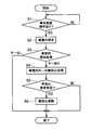
- the verification ECU 20 determines whether or not the locking operation of the vehicle 100 is performed by the smart key 3 (S1). This locking operation is performed by the locking operation based on the RF signal transmitted from the smart key 3 in response to the LF signal from the in-vehicle device 2 and the RF transmitted from the smart key 3 by the operation of the lock switch 35 (see FIG. 2). Includes both signal-based locking operations (RKE lock). Further, when the smart key 3 is provided with a mechanical key, the locking operation performed by inserting the mechanical key into a key cylinder provided on the outer surface of the vehicle door is also included in the locking operation in the process of S1. . On the other hand, the locking operation by the knob operation provided in the passenger compartment is not included in the locking operation in the process of S1.
- the verification ECU 20 instructs the vehicle interior LF antenna 22 to transmit an LF signal into the vehicle interior.
- authentication request data for requesting the smart key 3 that has received the LF signal to perform user authentication with the smartphone 4 is included in the LF signal.
- the RF receiver 24 receives an RF signal responding to the transmitted LF signal, the verification data included in the received RF signal is compared with the verification data held by the verification ECU 20. .
- the vehicle control system 1 when the vehicle control system 1 is provided with an immobilizer, the vehicle operation based on the immobilizer is also invalidated for the invalidated smart key 3.
- the immobilizer generates power in the transponder provided in the key by the radio wave generated from the radio wave generator when the key is brought close to the radio wave generator installed in the vehicle, and the generated power matches the vehicle from the key.
- the key is collated on the vehicle side by transmitting the business data, and the engine start is permitted when the collation is successful. According to this, even if the battery of the key runs out, the engine can be started.
- the verification ECU 20 operates the vehicle (locking / unlocking the vehicle door or starting the engine) with a smart key 3 other than the invalid smart key 3 (that is, the valid smart key). ), The invalidation of the invalidated smart key 3 is canceled.
- the control unit 30 of the smart key 3 determines whether or not an LF signal including authentication request data transmitted from the in-vehicle device 2 is received in S2 of FIG. 3 (S21). If there is no reception (S21: No), the processing in FIG. 4 is terminated.
- the RF receiving unit 33 When the LF signal including the authentication request data is received (S21: Yes), the RF receiving unit 33 is caused to transmit the RF signal indicating that the smart key 3 exists in the vehicle interior, thereby receiving the LF signal. Is responded to (S22).
- the RF signal to be transmitted here is a signal including its own ID and verification data for authenticating the key 3 on the in-vehicle device 2 side.
- the in-vehicle device 2 can recognize that the smart key 3 different from the smart key 3 used for the locking operation remains in the vehicle interior.
- the invalidation process of a vehicle interior key is performed by the process of S4 of FIG.
- the control unit 30 makes a user authentication request to the smartphone 4 (in other words, to the BT communication unit 42 of the smartphone 4) by wireless communication using the BT communication unit 34 (S23).
- This user authentication request is a process that is triggered by the reception of an LF signal including authentication request data. In other words, the user authentication request is automatically performed even if there is no user operation.
- user authentication of the smart key 3 is performed based on wireless communication between the BT communication units 34 and 42 (S24). Specifically, the user authentication data stored in the memory 31 of the control unit 30 and the user authentication data stored in the memory 41 of the smartphone 4 are collated. The collation may be performed on the smart key 3 side or on the smartphone 4 side. For example, when collation is performed on the smartphone 4 side, user authentication data held by the smart key 3 is transmitted to the smartphone 4. The smartphone 4 (control unit 40) collates the user authentication data held by itself with the authentication data from the smart key 3. If the verification is successful, the smartphone 4 transmits a signal indicating that the user authentication is successful to the smart key 3.
- User authentication may be performed as follows. That is, for example, when the smartphone 4 receives a user authentication request and user authentication data from the smart key 3, the smartphone 4 displays a message for prompting the input of the password on the display unit 43. Thereafter, when a password is input by the input unit 44, user authentication may be performed by checking the password against user authentication data (password) transmitted from the smart key 3.
- password user authentication data
- the smartphone 4 displays a message for prompting the input of the password on the display unit 43 and then transmits the password to the smart key 3 when the password is input by the input unit 44.
- the smart key 3 may perform user authentication by collating the password transmitted from the smartphone 4 with the user authentication data (password) held by the smart key 3.
- the user authentication request in S23 and the user authentication in S24 are processes that are established when pairing is performed in advance between the BT communication units 34 and 42 and wireless communication is possible.
- the smart key 3 and the smartphone 4 are located outside the communication range of the BT communication units 34 and 42 or are not paired because they are located within the communication range, that is, wireless communication If it is not in a possible state, user authentication fails.
- the control unit 30 determines whether the user authentication with the smartphone 4 is successful (S25). If the user authentication fails (S25: No), the process of FIG. 4 is terminated. In this case, a situation in which the smartphone 4 is not present in the vehicle interior or a situation in which pairing is not performed in advance even if the smartphone 4 is present in the vehicle interior is assumed.
- the RF transmitter 33 is caused to transmit an RF signal requesting activation (S26). At this time, its own ID is included in the RF signal. Thereby, the invalidation is canceled by the process of S6 in FIG. Thereafter, the process of FIG. 4 is terminated.
- the verification ECU 20 checks whether another smart key 3 exists in the vehicle interior, and if it exists, user authentication is performed.
- the vehicle operation function for the smart key 3 in the passenger compartment is immediately invalidated without waiting for the result. Then, after the invalidation, the invalidation is canceled when it is confirmed that the user authentication is successful.
- the authorized user when the authorized user remains in the vehicle on which the vehicle locking operation is performed, the user authentication is performed between the smart key 3 and the smartphone 4 carried by the authorized user, so that the smart key 3 Can be activated. Therefore, the authorized user who remains in the passenger compartment can perform vehicle operations such as engine start with the smart key 3 carried by himself / herself.
- the smart key 3 exists in a state where there is no authorized user in the vehicle interior, the user authentication of the smart key 3 fails and the smart key 3 can be invalidated. As a result, even if there is an intruder who has illegally entered the vehicle interior, it is possible to prevent the intruder from operating the vehicle using the smart key 3 in the vehicle interior, thereby ensuring security.
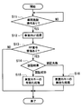
- the verification ECU 20 determines whether or not there is a vehicle locking operation by the smart key 3 (S11), similarly to the processing of S1 and S2 of FIG. (S11: Yes), an LF signal is transmitted to the vehicle interior LF antenna 22 to confirm whether another smart key 3 exists in the vehicle interior (S12).
- S12 as in the process of S2 of 5, authentication request data for requesting to perform user authentication is included in the LF signal.
- control unit 30 determines whether or not an LF signal including authentication request data transmitted from the in-vehicle device 2 in S12 of FIG. 6 has been received (S31). If not received (S31: No), the process of FIG. 7 is terminated.
- a user authentication request is made from the smart key 3 to the smartphone 4 based on the wireless communication between the BT communication units 34 and 42 as in S23 to S25 of FIG. Thereafter, user authentication is performed (S32, S33, S34).
- the smartphone 4 in FIG. 1 is configured to be able to perform an input operation for requesting the start of user authentication using the input unit 44.
- the control unit 40 transmits a signal requesting the start of user authentication to the smart key 3 using the BT communication unit 42. .
- FIG. 9 is executed, for example, after a negative determination is made in S5 in FIG. 3, or is executed after the process in S16 in FIG.
- the process of FIG. 10 is executed, for example, after a negative determination is made in S25 in FIG. 4, or is executed after the process of S36 in FIG.
- the control unit 30 determines whether or not a signal requesting the start of user authentication is received from the smartphone 4 (S41). When there is no reception (S41: No), it waits until there is reception.
- the BT communication unit 34 receives a signal from the smartphone 4 (S41: Yes)
- the smart key 3 to the smartphone based on the wireless communication between the BT communication units 34 and 42 as in S23 to S25 of FIG.
- user authentication is performed (S42, S43, S44). If the user authentication is successful (S44: Yes), an RF signal requesting validation is transmitted (S45). If the user authentication has failed (S44: No), the processing in FIG. 7 is terminated.
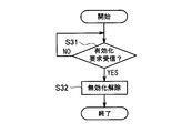
- the verification ECU 20 determines whether or not the validation request signal transmitted from the smart key 3 is received in S45 of FIG. 10 (S31). When there is no reception (S31: No), it waits until there is reception. When the validation request signal is received (S31: Yes), the invalidation of the smart key 3 is canceled (S32). Then, the process of FIG. 9 is complete
- the timing chart of FIG. 11 shows an example in which the invalidation is canceled by the processing of FIGS. 9 and 10 after the smart key is invalidated by the method of the second embodiment.
- the smart key 3 and the smartphone 4 are not close to the communicable range or are close, pairing is not performed. Therefore, even if the smart key 3 in the passenger compartment is disabled by the processing of the first and second embodiments, the passenger who notices that the smart key 3 is disabled manually starts user authentication. Therefore, the smart key 3 can be validated after the fact.
- a user authentication of a vehicle interior smart key may be performed using a portable device having a communication function carried by a regular user other than a smartphone.
- a portable device having a communication function carried by a regular user other than a smartphone.
- Bluetooth registered trademark
- other wireless communication standards for example, infrared communication, wireless LAN, NFC (Near Field Communication)
- Etc. or based on wired communication
- user authentication may be performed.
- the user authentication of the smart key is successful when the communication between the smart key and the smartphone is established.
- the user authentication is successful when the BT communication unit of the smart key and the BT communication unit of the smartphone are paired, and the user authentication is performed when the pair is not paired. Let's assume failure. According to this, since it is not necessary to perform verification of user authentication data held by the smart key and the smartphone after pairing, it is easily determined whether or not the user using the smart key is an authorized user. it can.
- an input unit for inputting secret information for user authentication is provided in the smart key, and information input from the input unit based on a user operation is compared with secret information stored in advance in the smart key. If the verification is successful, the user authentication may be successful.
- the lock switch and the unlock switch originally provided in the smart key may be used as an input unit for inputting secret information.
- the user authentication when performing user authentication, when the user operates the lock switch and the unlock switch and the operation pattern matches a specific operation pattern, the user authentication is successful. For example, when the lock switch operation is 1, the unlock switch operation is 0, and the secret information is 1011, the user authentication is successful when the lock switch, the unlock switch, the lock switch, and the lock switch are operated in this order. Become.
- the smart key is provided with an input unit for inputting the user's biometric information (fingerprint, voice, etc.) and a storage unit for storing the legitimate user's biometric information (fingerprint, voice, etc.). Then, user authentication may be performed by comparing biometric information input from the input unit with biometric information stored in the storage unit.
- the verification ECU 20 corresponds to a permission unit.
- the control unit 30 that executes the processes of S23 and S24 in FIG. 4, S32 and S33 in FIG. 7, and S41 to S43 in FIG. 10 corresponds to the authentication unit.
- the control unit 30 and the RF transmission unit 33 that execute the processes of S25 and S26 in FIG. 4, S34 to S36 in FIG. 7, and S44 and S45 in FIG. 10 correspond to the transmission unit.
- the validation request signal or the invalidation request signal transmitted in S26 of FIG. 4, S35, S36 of FIG. 7, and S45 of FIG. 10 corresponds to the authentication result signal.
- the smartphone 4 corresponds to a mobile device.
- the LF signal transmitted in S2 of FIG. 3 and S12 of FIG. 6 corresponds to the confirmation signal.
Landscapes
- Engineering & Computer Science (AREA)
- Mechanical Engineering (AREA)
- Signal Processing (AREA)
- Physics & Mathematics (AREA)
- General Physics & Mathematics (AREA)
- Computer Networks & Wireless Communication (AREA)
- Lock And Its Accessories (AREA)
- Selective Calling Equipment (AREA)
- Telephone Function (AREA)
Abstract
La présente invention concerne un système de commande de véhicule comprenant un dispositif embarqué de véhicule (2) et une clé (3). Sur la base du verrouillage du véhicule par une première clé, une unité de confirmation (S1-S3, S11-S13, 20, 22, 24) du dispositif embarqué de véhicule confirme la présence d'une seconde clé, différente de la première clé, à l'intérieur d'un véhicule. Une unité d'authentification de clé (S23, S24, S32, S33, S41-S43, 30) authentifie l'utilisateur de la clé en tant qu'utilisateur autorisé. Une unité de contrôle de validité (S4-S6, S14-S16, S31, S32, 20) du dispositif embarqué de véhicule désactive la fonctionnalité d'une unité d'autorisation (20) par rapport à la seconde clé lorsque la seconde clé est présente à l'intérieur du véhicule et que l'authentification de la seconde clé a échoué. L'unité de contrôle de validité active la fonctionnalité de l'unité d'autorisation par rapport à la seconde clé lorsque la seconde clé est présente à l'intérieur du véhicule et que l'authentification de la seconde clé a réussi.
Priority Applications (3)
| Application Number | Priority Date | Filing Date | Title |
|---|---|---|---|
| CA3007323A CA3007323A1 (fr) | 2015-12-14 | 2016-11-21 | Systeme de commande de vehicule |
| US16/061,359 US10220814B2 (en) | 2015-12-14 | 2016-11-21 | Vehicle control system |
| EP16875336.6A EP3392433A4 (fr) | 2015-12-14 | 2016-11-21 | Système de commande de véhicule |
Applications Claiming Priority (2)
| Application Number | Priority Date | Filing Date | Title |
|---|---|---|---|
| JP2015-242992 | 2015-12-14 | ||
| JP2015242992A JP6372707B2 (ja) | 2015-12-14 | 2015-12-14 | 車両制御システム |
Publications (1)
| Publication Number | Publication Date |
|---|---|
| WO2017104352A1 true WO2017104352A1 (fr) | 2017-06-22 |
Family
ID=59056334
Family Applications (1)
| Application Number | Title | Priority Date | Filing Date |
|---|---|---|---|
| PCT/JP2016/084439 Ceased WO2017104352A1 (fr) | 2015-12-14 | 2016-11-21 | Système de commande de véhicule |
Country Status (5)
| Country | Link |
|---|---|
| US (1) | US10220814B2 (fr) |
| EP (1) | EP3392433A4 (fr) |
| JP (1) | JP6372707B2 (fr) |
| CA (1) | CA3007323A1 (fr) |
| WO (1) | WO2017104352A1 (fr) |
Cited By (1)
| Publication number | Priority date | Publication date | Assignee | Title |
|---|---|---|---|---|
| WO2019203305A1 (fr) * | 2018-04-20 | 2019-10-24 | 株式会社東海理化電機製作所 | Système de partage |
Families Citing this family (14)
| Publication number | Priority date | Publication date | Assignee | Title |
|---|---|---|---|---|
| JP7166780B2 (ja) * | 2017-08-03 | 2022-11-08 | パナソニック インテレクチュアル プロパティ コーポレーション オブ アメリカ | 車両制御装置、車両制御方法及びプログラム |
| KR102444390B1 (ko) * | 2017-10-23 | 2022-09-19 | 현대자동차주식회사 | 차량, 차량 보안 시스템 및 차량 보안 방법 |
| US10009325B1 (en) * | 2017-12-07 | 2018-06-26 | Karamba Security | End-to-end communication security |
| WO2020174544A1 (fr) * | 2019-02-25 | 2020-09-03 | 本田技研工業株式会社 | Véhicule, dispositif embarqué sur un véhicule et procédé de gestion |
| JP2020176442A (ja) * | 2019-04-18 | 2020-10-29 | 株式会社東海理化電機製作所 | 通信制御システム及び通信制御方法 |
| CN112744180B (zh) * | 2019-10-29 | 2023-04-28 | 现代自动车株式会社 | 用于连接的车辆控制的系统和方法 |
| JP7338565B2 (ja) * | 2020-06-01 | 2023-09-05 | トヨタ自動車株式会社 | 情報処理装置、認証システム、情報処理方法、およびプログラム |
| CN112277876A (zh) * | 2020-11-02 | 2021-01-29 | 东风汽车集团有限公司 | 一种防误解锁的汽车无钥匙进入控制方法及存储介质 |
| JP7614823B2 (ja) * | 2020-12-16 | 2025-01-16 | 文化シヤッター株式会社 | 開閉装置及び開閉制御方法 |
| KR102909573B1 (ko) * | 2021-06-07 | 2026-01-08 | 현대자동차주식회사 | 차량 및 그 제어 방법 |
| JP7642493B2 (ja) * | 2021-08-25 | 2025-03-10 | 株式会社東海理化電機製作所 | 認証システム、およびユーザインターフェース装置 |
| JP7632188B2 (ja) * | 2021-08-31 | 2025-02-19 | トヨタ自動車株式会社 | 情報処理装置及びこれを備えた車両、情報処理方法、並びにプログラム |
| KR102578492B1 (ko) * | 2021-12-15 | 2023-09-14 | 주식회사 케이티앤지 | 사용자 인증 방법 및 장치 |
| KR20250079250A (ko) * | 2022-06-13 | 2025-06-04 | 글로벌모빌리티서비스 주식회사 | 제어 장치 및 제어 시스템 |
Citations (2)
| Publication number | Priority date | Publication date | Assignee | Title |
|---|---|---|---|---|
| JP4389838B2 (ja) * | 2005-05-11 | 2009-12-24 | トヨタ自動車株式会社 | 遠隔操作装置、遠隔操作装置の制御方法、遠隔操作システム |
| JP2014152458A (ja) * | 2013-02-06 | 2014-08-25 | Calsonic Kansei Corp | 車両用キーレスシステム |
Family Cites Families (5)
| Publication number | Priority date | Publication date | Assignee | Title |
|---|---|---|---|---|
| US8725113B2 (en) | 2012-03-12 | 2014-05-13 | Google Inc. | User proximity control of devices |
| US8943187B1 (en) * | 2012-08-30 | 2015-01-27 | Microstrategy Incorporated | Managing electronic keys |
| JP6108097B2 (ja) | 2013-05-10 | 2017-04-05 | 株式会社デンソー | 制御システム |
| JP6142775B2 (ja) | 2013-10-28 | 2017-06-07 | 株式会社デンソー | 車両用エンジン始動操作システム |
| CN105830470A (zh) * | 2013-11-22 | 2016-08-03 | 高通股份有限公司 | 用于基于用车辆内的多个移动计算设备提供的偏好来配置车辆的内部的系统和方法 |
-
2015
- 2015-12-14 JP JP2015242992A patent/JP6372707B2/ja not_active Expired - Fee Related
-
2016
- 2016-11-21 US US16/061,359 patent/US10220814B2/en not_active Expired - Fee Related
- 2016-11-21 EP EP16875336.6A patent/EP3392433A4/fr not_active Withdrawn
- 2016-11-21 CA CA3007323A patent/CA3007323A1/fr not_active Abandoned
- 2016-11-21 WO PCT/JP2016/084439 patent/WO2017104352A1/fr not_active Ceased
Patent Citations (2)
| Publication number | Priority date | Publication date | Assignee | Title |
|---|---|---|---|---|
| JP4389838B2 (ja) * | 2005-05-11 | 2009-12-24 | トヨタ自動車株式会社 | 遠隔操作装置、遠隔操作装置の制御方法、遠隔操作システム |
| JP2014152458A (ja) * | 2013-02-06 | 2014-08-25 | Calsonic Kansei Corp | 車両用キーレスシステム |
Non-Patent Citations (1)
| Title |
|---|
| See also references of EP3392433A4 * |
Cited By (5)
| Publication number | Priority date | Publication date | Assignee | Title |
|---|---|---|---|---|
| WO2019203305A1 (fr) * | 2018-04-20 | 2019-10-24 | 株式会社東海理化電機製作所 | Système de partage |
| JP2019191752A (ja) * | 2018-04-20 | 2019-10-31 | 株式会社東海理化電機製作所 | シェアリングシステム |
| CN111989723A (zh) * | 2018-04-20 | 2020-11-24 | 株式会社东海理化电机制作所 | 共享系统 |
| JP7028703B2 (ja) | 2018-04-20 | 2022-03-02 | 株式会社東海理化電機製作所 | シェアリングシステム |
| CN111989723B (zh) * | 2018-04-20 | 2022-09-30 | 株式会社东海理化电机制作所 | 共享系统 |
Also Published As
| Publication number | Publication date |
|---|---|
| JP6372707B2 (ja) | 2018-08-15 |
| EP3392433A1 (fr) | 2018-10-24 |
| EP3392433A4 (fr) | 2018-12-19 |
| CA3007323A1 (fr) | 2017-06-22 |
| US10220814B2 (en) | 2019-03-05 |
| JP2017110338A (ja) | 2017-06-22 |
| US20180361991A1 (en) | 2018-12-20 |
Similar Documents
| Publication | Publication Date | Title |
|---|---|---|
| JP6372707B2 (ja) | 車両制御システム | |
| JP6308181B2 (ja) | 車両制御システム | |
| US10196039B2 (en) | System and method for keyless entry and remote starting vehicle with an OEM remote embedded in vehicle | |
| JP6294109B2 (ja) | スマートシステム | |
| JP7053216B2 (ja) | 車両操作装置および車両システム | |
| JP5529783B2 (ja) | 電子キーシステム | |
| CN112365632A (zh) | 车辆进入隐私模式的nfc激活 | |
| US20220198856A1 (en) | Communication control system and communication control method | |
| KR102071406B1 (ko) | 차량 탑재 장치 및 인증 시스템 | |
| JP2016079600A (ja) | 車両用認証システム | |
| JP2016171486A (ja) | 車両無線通信システム、車両制御装置、携帯機 | |
| JP6954801B2 (ja) | キーユニットおよび制御システム | |
| US20190110199A1 (en) | Car sharing system | |
| JP2018062306A (ja) | 生体認証併用電子キーシステム | |
| JP2016168946A (ja) | 車両無線通信システム、車両制御装置、携帯機 | |
| US11110894B2 (en) | Car sharing system | |
| JP2012177242A (ja) | 電子キーシステム | |
| JP2012144906A (ja) | 電子キーシステム | |
| JP2007016505A (ja) | 車両用通信装置 | |
| JP2017088016A (ja) | 車載機器制御システム、携帯機 | |
| JP6894345B2 (ja) | 無線通信システム | |
| KR20130113160A (ko) | 자동차 시동 제어 방법 및 장치 | |
| JP2015078523A (ja) | 車両制御システム | |
| JP6663886B2 (ja) | カーシェアリングシステム | |
| JP6341473B2 (ja) | 電子キーシステム |
Legal Events
| Date | Code | Title | Description |
|---|---|---|---|
| 121 | Ep: the epo has been informed by wipo that ep was designated in this application |
Ref document number: 16875336 Country of ref document: EP Kind code of ref document: A1 |
|
| ENP | Entry into the national phase |
Ref document number: 3007323 Country of ref document: CA |
|
| NENP | Non-entry into the national phase |
Ref country code: DE |