WO2017111013A1 - Compresseur à palettes - Google Patents
Compresseur à palettes Download PDFInfo
- Publication number
- WO2017111013A1 WO2017111013A1 PCT/JP2016/088363 JP2016088363W WO2017111013A1 WO 2017111013 A1 WO2017111013 A1 WO 2017111013A1 JP 2016088363 W JP2016088363 W JP 2016088363W WO 2017111013 A1 WO2017111013 A1 WO 2017111013A1
- Authority
- WO
- WIPO (PCT)
- Prior art keywords
- vane
- pressure chamber
- back pressure
- chamber
- rotor
- Prior art date
- Legal status (The legal status is an assumption and is not a legal conclusion. Google has not performed a legal analysis and makes no representation as to the accuracy of the status listed.)
- Ceased
Links
Images




Classifications
-
- F—MECHANICAL ENGINEERING; LIGHTING; HEATING; WEAPONS; BLASTING
- F04—POSITIVE - DISPLACEMENT MACHINES FOR LIQUIDS; PUMPS FOR LIQUIDS OR ELASTIC FLUIDS
- F04C—ROTARY-PISTON, OR OSCILLATING-PISTON, POSITIVE-DISPLACEMENT MACHINES FOR LIQUIDS; ROTARY-PISTON, OR OSCILLATING-PISTON, POSITIVE-DISPLACEMENT PUMPS
- F04C18/00—Rotary-piston pumps specially adapted for elastic fluids
- F04C18/30—Rotary-piston pumps specially adapted for elastic fluids having the characteristics covered by two or more of groups F04C18/02, F04C18/08, F04C18/22, F04C18/24, F04C18/48, or having the characteristics covered by one of these groups together with some other type of movement between co-operating members
- F04C18/34—Rotary-piston pumps specially adapted for elastic fluids having the characteristics covered by two or more of groups F04C18/02, F04C18/08, F04C18/22, F04C18/24, F04C18/48, or having the characteristics covered by one of these groups together with some other type of movement between co-operating members having the movement defined in group F04C18/08 or F04C18/22 and relative reciprocation between the co-operating members
- F04C18/344—Rotary-piston pumps specially adapted for elastic fluids having the characteristics covered by two or more of groups F04C18/02, F04C18/08, F04C18/22, F04C18/24, F04C18/48, or having the characteristics covered by one of these groups together with some other type of movement between co-operating members having the movement defined in group F04C18/08 or F04C18/22 and relative reciprocation between the co-operating members with vanes reciprocating with respect to the inner member
-
- F—MECHANICAL ENGINEERING; LIGHTING; HEATING; WEAPONS; BLASTING
- F04—POSITIVE - DISPLACEMENT MACHINES FOR LIQUIDS; PUMPS FOR LIQUIDS OR ELASTIC FLUIDS
- F04C—ROTARY-PISTON, OR OSCILLATING-PISTON, POSITIVE-DISPLACEMENT MACHINES FOR LIQUIDS; ROTARY-PISTON, OR OSCILLATING-PISTON, POSITIVE-DISPLACEMENT PUMPS
- F04C29/00—Component parts, details or accessories of pumps or pumping installations, not provided for in groups F04C18/00 - F04C28/00
Definitions
- the present invention relates to a vane type compressor provided with a vane having a structure useful for coping with problems caused by compressing oil accumulated in a back pressure chamber at the bottom of the vane groove.
- Patent Document 1 Japanese Patent Application Laid-Open No. 57-26293 discloses a compression chamber in which a rotor provided with a vane is arranged in a chamber composed of a cylinder and side blocks provided on both sides thereof, and the rotor rotates.
- a vane type compressor that compresses by expanding or contracting, low pressure pressure is guided into the vane pressing chamber formed by the lower end of the vane and a groove formed in the rotor during the suction stroke, and the vane pressing chamber is shut off during the compression stroke.
- a vane type compressor is disclosed in which when the compressed fluid from the compression chamber is discharged from the discharge hole, the vane pressing chamber opens to the high pressure side or the low pressure side to release the pressure in the vane pressing chamber.
- Patent Document 1 As a countermeasure against this, in Patent Document 1, the back pressure chamber is made an independent space in the compression stroke, and the pressure of the back pressure chamber is increased against the drawing of the vane. I am doing so.
- the vane type compressor that confins the back pressure chamber in this way, when the ratio of liquid such as oil in the back pressure chamber is large, the pressure becomes too large due to liquid compression by the vane, There were problems such as increased sliding friction at the tip of the vane and a lower coefficient of performance.
- Patent Document 2 Japanese Utility Model Publication No. 02-204708 configures a compressor body by fixing side blocks on both sides of a cylinder, and arranges a rotor in which vanes are inserted and inserted in the compressor body.
- a vane type compressor that constitutes a back pressure chamber surrounded by a rotor, a vane, and a side block, and this back pressure chamber becomes an independent space in the compression stroke, the back pressure chamber communicates with the side block in the compression stroke.
- a vane compressor having a blind hole for a damper.
- the vane in the compression stroke, the vane is gradually pushed into the vane groove along the inner surface of the cylinder to reduce the volume of the back pressure chamber.
- the pressure in the back pressure chamber escapes to the damper blind hole and the pressure in the back pressure chamber is prevented from rising abnormally.
- Patent Document 3 Japanese Patent Application Laid-Open No. 09-329094 describes a back pressure groove that communicates with the vane back pressure chamber in the entire section until the tip of the vane reaches the vicinity of the suction port start end, and oil in the back pressure chamber.
- a control oil pressure chamber that communicates with the high pressure chamber via the first passage, and communicates with the vane back pressure chamber in the section from the vicinity of the discharge port start end to the suction port start end.
- the second passage for releasing the high-pressure vane back pressure to the control pressure chamber is connected to the both passages via the control pressure chamber when the discharge pressure is lower than a predetermined value, and when the discharge pressure is higher than the predetermined value,
- a vane compressor that includes a spool valve that blocks communication.
- the present invention provides a vane type compressor having a vane having a structure capable of effectively avoiding an abnormal pressure increase in the back pressure chamber due to compression of the liquid accumulated in the back pressure chamber of the vane. It is to provide.
- the present invention provides a housing, a cylinder portion provided with a cam surface and provided in the housing, and a pair of side block portions that close both ends in the axial direction of the cylinder portion, A drive shaft rotatably supported by the pair of side block portions; a rotor fixed to the drive shaft and rotatably accommodated in the cylinder portion; and a plurality of vane grooves formed in the rotor; A plurality of vanes that are slidably inserted into the vane grooves and have tip portions protruding and retracting from the vane grooves and sliding on the cam surface; a back pressure chamber located at the bottom of the vane grooves; and the cylinder portion; In a space closed by the pair of side block portions, a compression chamber formed by the rotor and the vane, a suction port for sucking fluid into the compression chamber, and before being compressed in the compression chamber A discharge port that discharges fluid; a high-pressure chamber that stores fluid discharged from the discharge port; an oil reservoir
- the recess structure is preferably a notch formed between both side end portions of the vane bottom surface portion in the axial direction, and is formed at both side end portions in the axial direction of the bottom surface portion of the vane. It can be a notch.
- the dent structure is a notch formed between both side ends of the bottom surface of the vane in the axial direction and on one side in the thickness direction of the vane.
- the said recessed structure may be a notch part formed in the one side of the thickness direction of the said vane over the full length of the axial direction of the said vane bottom face part.
- the recess structure is a notch formed on the opposite side of the moving direction of the vane by the rotation of the rotor.
- the concave structure is a groove portion having a predetermined depth formed in a central portion in the thickness direction of the vane between both end portions of the vane bottom surface portion in the axial direction.
- the vane compressor is provided with a second communication passage that connects the back pressure chamber and the high pressure chamber in a closed section in which communication between the recess and the back pressure chamber is closed. Accordingly, oil in the back pressure chamber can be released to the high pressure chamber in a closed section where communication between the recess and the back pressure chamber is closed.
- the back pressure chamber and the second communication path are formed by the notch portions formed at both end portions in the axial direction of the vane bottom surface portion or over the entire axial length of the vane bottom surface portion. Since the area of the opening is sufficiently secured, oil can be efficiently released to the high pressure chamber, and an abnormal increase in the pressure of the back pressure chamber can be suppressed.
- the recess structure for enlarging the volume of the back pressure chamber at the bottom surface of the vane, the compressibility of the oil in the back pressure chamber by the vane is achieved. Is reduced, and an abnormal increase in the pressure of the back pressure chamber can be prevented.
- the recessed structure is formed at both end portions of the vane bottom surface portion, or is formed in the entire axial direction of the vane bottom surface portion, thereby opening the back pressure chamber and the second communication path. Is sufficiently secured and oil can be discharged efficiently, so that an abnormal increase in the pressure in the back pressure chamber can be prevented.
- FIG. 1 is a side sectional view of a vane type compressor according to the present invention.
- FIG. 2 is a front sectional view of the vane type compressor shown in FIG.
- FIG. 3 is an explanatory view showing the vane according to the first embodiment used in the vane type compressor shown in FIG. 1, wherein (a) is a front view thereof and (b) is a side view thereof.
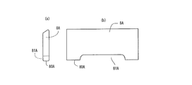
- FIG. 4 is an explanatory view showing a vane according to a second embodiment used in the vane type compressor shown in FIG. 1, wherein (a) is a front view thereof and (b) is a side view thereof.
- FIG. 5 is an explanatory view showing a vane according to a third embodiment used in the vane type compressor shown in FIG.
- FIG. 6 is an explanatory view showing a vane according to a fourth embodiment used in the vane type compressor shown in FIG. 1, wherein (a) is a front view thereof and (b) is a side view thereof.
- FIG. 7 is an explanatory view showing a vane according to a fifth embodiment used in the vane type compressor shown in FIG. 1, wherein (a) is a front view thereof and (b) is a side view thereof.
- FIG. 8 is an explanatory view showing a vane according to a sixth embodiment used in the vane type compressor shown in FIG. 1, wherein (a) is a front view thereof and (b) is a side view thereof.
- FIG. 6 is an explanatory view showing a vane according to a fourth embodiment used in the vane type compressor shown in FIG. 1, wherein (a) is a front view thereof and (b) is a side view thereof.
- FIG. 7 is an explanatory view showing a vane according to a fifth embodiment used in the vane type compressor shown in FIG
- FIG. 9 is an explanatory view showing a vane according to a seventh embodiment used in the vane type compressor shown in FIG. 1, wherein (a) is a front view thereof and (b) is a side view thereof.
- FIG. 10 is an explanatory view showing a vane according to an eighth embodiment used in the vane type compressor shown in FIG. 1, wherein (a) is a front view thereof and (b) is a side view thereof.
- FIG. 11 is an explanatory view showing a communication state between the high-pressure gas introduction hole and the back pressure chamber.
- FIG. 12 is an explanatory diagram illustrating a load related to the vane and the vane groove.
- the vane compressor 1 includes a cylinder block 3 in which a cylinder portion 3a in which a cam surface 2 is formed and a rear side block portion 3b that closes one end of the cylinder portion 3a are integrally formed. 3 and a housing 4 in which a front side block 4b and a shell forming portion 4a are integrally formed and closes the other end of the cylinder 3a, and one end is on the rear side block 3b.
- a drive shaft 5 that is rotatably supported by the front side block 4b, a rotor 6 that is fixed to the drive shaft 5 and rotates as the drive shaft 5 rotates, and that the rotor 6 is circumferentially equidistant.
- a discharge chamber 12 defined between them and communicating with the compression chamber 9 via the discharge port 11 is provided. Further, the discharge port 11 is provided with a discharge valve 13, and the communication between the discharge port 11 and the discharge chamber 12 is opened and closed.
- a back pressure chamber 70 facing the vane bottom surface portion 80 is formed at the lower end portion of the vane groove 7.
- a high-pressure chamber 14 is formed at the upper portion thereof, and an oil reservoir chamber 15 is formed at the lower portion thereof.
- the side block portions 3b and 4b are formed with a recess 16 through which the back pressure chamber 70 communicates in a stroke in which the tip of the vane is in front of the discharge port from the suction port.
- the recess 16 receives oil from the oil reservoir chamber 18 in which oil separated from the working fluid by an oil separator (not shown) (having a pressure corresponding to the pressure of the discharge gas) is accumulated. Is supplied via a communication path).
- the rear side block 3b is provided with a high-pressure gas introduction hole 18a that communicates with the back pressure chamber 70 in a closed section in which communication between the recess 16 and the back pressure chamber 70 is closed. . Further, a high-pressure gas introduction path 18 (second communication path) that communicates the high-pressure gas introduction hole 18a and the high-pressure chamber 14 is provided.
- the back pressure chamber 70 communicates with the high pressure chamber 14 via the high pressure gas introduction hole 18a and the high pressure gas introduction passage 18 (second communication passage).
- the vane 8 is a recess for expanding the volume of the back pressure chamber 70 in an intermediate portion in the axial direction of the vane bottom surface portion 80 as shown in FIG.
- the structure has an intermediate cutout portion 81, and end cutout portions 82 and 83 are formed at both axial ends of the vane bottom surface portion 80.
- oil in the back pressure chamber 70 is compressed by the vane 8 that enters the back pressure chamber 70 from the vane groove 7 in the compression stroke, but the back pressure is reduced by the intermediate notch 81 and the end notches 82 and 83. Since the volume of the chamber 70 is increased as compared with the case where the notched portions 81, 82, 83 are not provided, the oil compression rate is reduced and the pressure of the back pressure chamber 70 can be prevented from becoming abnormally high. .
- the back pressure chamber 70 and the high pressure gas introduction hole 18a are communicated to introduce high pressure gas into the back pressure chamber 70, so that the tip of the vane 8 is securely attached to the cam surface 2. I try to make it slide.
- the pressure in the back pressure chamber 70 becomes too high, the pressure in the back pressure chamber 70 increases by releasing high pressure oil to the high pressure chamber 14 through the high pressure gas introduction hole 18 a and the high pressure gas introduction path 18. Can be suppressed.
- FIG. 11 in the case of the conventional vane, since the lower end portion of the vane 8 enters the back pressure chamber 70, there arises a problem that the opening 18b of the high pressure gas introduction hole 18a becomes very narrow.
- one cutout portion 83 ensures a sufficient area of the opening 18b with respect to the high pressure gas introduction hole 18a. Further, the other notch portion 82 is formed for weight balance with the one notch portion 83.
- the intermediate cutout 81 described above may be either an arch shape or a square shape.
- the vane 8A according to the second embodiment shown in FIG. 4 does not form the end cutout portions 82 and 83 but forms the intermediate cutout portion 81A larger than the vane 8 according to the first embodiment described above. It is a thing.
- the intermediate notch 81A may be arched or rectangular. Further, the second embodiment is characterized in that the intermediate notch 81A is formed in a sufficient size.
- the vane 8B according to the third embodiment shown in FIG. 5 is characterized in that a plurality of intermediate notches 81B are provided with respect to the vane 8 according to the first embodiment described above.
- a plurality of intermediate notches 81B are provided with respect to the vane 8 according to the first embodiment described above.
- the reinforcing portion 84B it is possible to form the reinforcing portion 84B for maintaining the strength between the intermediate notches 81B. For this reason, the intensity
- the vane 8C according to the fourth embodiment shown in FIG. 6 is provided with only the end cutout portions 82C and 83C without forming the intermediate cutout portion 81 with respect to the vane 8 according to the first embodiment described above. It is characterized by.
- the volume of the back pressure chamber 70 can be increased by the end cutout portions 82C and 83C, and further, for example, the one end cutout portion 83C can be used to connect the back pressure chamber 70 and the high pressure gas introduction hole 18a. Since the area of the opening 18b is sufficiently secured, an abnormal increase in the pressure of the back pressure chamber 70 can be suppressed or prevented.
- the vane 8D according to the fifth embodiment shown in FIG. 7 has a one-side notch 85D cut out on one side in the thickness direction of the vane 8D along the axial direction of the vane bottom surface portion 80D.
- the volume of the back pressure chamber 70 can be secured by the one-side cutout portion 85D, and the back pressure chamber 70 and the high-pressure gas introduction hole 18a are formed by one end portion of the one-side cutout portion 85D. Since the area of the opening 18b is sufficiently secured, an abnormal increase in the pressure of the back pressure chamber 70 can be suppressed or prevented.
- the one-side notch 85D is formed on the opposite side of the direction in which the vane 8D moves due to the rotation of the rotor 6. As shown in FIG. 12, when the rotor 6 rotates in the direction indicated by A, a force in the direction indicated by B acts on the vane 8 due to the compression reaction force, and between the vane groove 7 and the vane 8. Since there is a sliding clearance, the vane groove 7 and the vane 8 come into contact at the contact portions 87 and 88.
- the one-side cutout portion 85D is formed on the front side in the direction in which the vane moves, the length in which the vane 8 contacts the inner wall of the vane groove 7 in the axial direction of the contact portion 87 is shortened. This causes a problem that the vane groove 7 or the vane 8 of the rotor 6 is easily worn.
- the one-side cutout portion 85D is formed on the opposite side of the direction in which the vane moves, so the axial contact length of the contact portion 87 is not shortened, An increase in the contact pressure between the vane 8 and the vane groove 7 can be avoided.
- the rotor 6 is formed of an aluminum material and the vane 8 is formed of a sintered iron material, and the rotor side (vane groove side) is easily worn.
- the axial contact length is increased. An increase in local contact pressure can be suppressed, and wear can be avoided.
- the vane 8E according to the sixth embodiment shown in FIG. 8 is partially cut on one side of the vane bottom surface portion 80E in a predetermined range of the intermediate portion along the axial direction and cut out on one side in the thickness direction of the vane 8E. It has the notch part 85E.
- the vane 8E according to the sixth embodiment has a shape in which both sides of the one-side partially cut-out portion 85E are closed. Since both ends serve as reinforcing columns, the back pressure chamber 70 is used. It is possible to maintain a sufficient strength of the vane while securing the volume.
- the one-side partially cutout portion 85E is formed on the opposite side of the moving direction of the vane.
- the contact length in the axial direction of 87 is not shortened, and the contact pressure between the vane 8 and the vane groove 7 can be avoided from increasing.
- the rotor side in the rotor 6 made of aluminum and the vane 8 made of a sintered material, the rotor side (vane groove side) is likely to be worn. As described above, by increasing the contact length in the axial direction, it is possible to suppress an increase in local contact pressure and to avoid wear.
- the vane 8F according to the seventh embodiment shown in FIG. 9 has a plurality of partially cut-out portions 85F on one side cut out at a predetermined interval along the axial direction of the vane bottom surface portion 80F.
- the portion between the one-side partially cutout portions 85F and both ends thereof serve as reinforcing columns.
- the one-side partially cut-out portion 85F is formed on the side opposite to the moving direction of the vane.
- the contact length in the axial direction of 87 is not shortened, and the contact pressure between the vane 8 and the vane groove 7 can be avoided from increasing. Also in this Example 7, as in the case of Example 5 described above, in the rotor 6 made of aluminum and the vane 8 made of a sintered material, the rotor side (vane groove side) is likely to be worn. As described above, by increasing the contact length in the axial direction, it is possible to suppress an increase in local contact pressure and to avoid wear.
- the vane 8G according to the eighth embodiment illustrated in FIG. 10 is a groove portion 86G having a predetermined depth from the vane bottom surface portion 80G in the intermediate portion in the axial direction of the vane bottom surface portion 80G and in the intermediate portion in the thickness direction of the vane 8G. Is formed.
- the volume of the back pressure chamber 70 can be expanded by the groove portion 86G having a predetermined depth, and the periphery of the groove portion 86G is surrounded by the wall portion, so that the strength of the vane bottom surface portion 80G is increased. It can be maintained.
- the vanes 8, 8A to 8G according to the present invention have a structure in which the volume of the back pressure chamber 70 formed in the rotor 6 is increased. It can be solved. Further, in the vanes 8, 8C, 8D according to the present invention, since the area of the opening 18b between the back pressure chamber 70 and the high pressure gas introduction hole 18a is sufficiently secured, the pressure in the back pressure chamber 70 is abnormally increased. Can be suppressed or prevented.
Landscapes
- Engineering & Computer Science (AREA)
- Mechanical Engineering (AREA)
- General Engineering & Computer Science (AREA)
- Rotary Pumps (AREA)
Abstract
L'invention concerne un compresseur à palettes, lequel est équipé de palettes dont la structure permet d'éviter efficacement une augmentation anormale de pression dans la chambre de contre-pression, cette augmentation étant due à la compression de liquide accumulé dans la chambre de contre-pression. Selon l'invention, des palettes sont introduites de façon coulissante dans chacune des fentes (7) formées dans un rotor (6) qui définit un espace de compression entre le rotor et la surface périphérique interne d'un cylindre (3a). L'extrémité de ces palettes appuie contre la surface périphérique interne du cylindre (3a) à cause de la pression dans les chambres (70) de contre-pression situées au fond des fentes (7). Une structure en retrait permettant d'augmenter le volume des chambres (70) de contre-pression est formée dans les surfaces inférieures (80) des palettes, ces surfaces inférieures étant opposées aux chambres (70) de contre-pression.
Applications Claiming Priority (2)
| Application Number | Priority Date | Filing Date | Title |
|---|---|---|---|
| JP2015252193 | 2015-12-24 | ||
| JP2015-252193 | 2015-12-24 |
Publications (1)
| Publication Number | Publication Date |
|---|---|
| WO2017111013A1 true WO2017111013A1 (fr) | 2017-06-29 |
Family
ID=59090392
Family Applications (1)
| Application Number | Title | Priority Date | Filing Date |
|---|---|---|---|
| PCT/JP2016/088363 Ceased WO2017111013A1 (fr) | 2015-12-24 | 2016-12-22 | Compresseur à palettes |
Country Status (1)
| Country | Link |
|---|---|
| WO (1) | WO2017111013A1 (fr) |
Citations (6)
| Publication number | Priority date | Publication date | Assignee | Title |
|---|---|---|---|---|
| JPS55112085U (fr) * | 1979-01-31 | 1980-08-06 | ||
| JPS5829189U (ja) * | 1981-08-20 | 1983-02-25 | セイコ−精機株式会社 | 気体圧縮機 |
| JP2006077597A (ja) * | 2004-09-07 | 2006-03-23 | Calsonic Compressor Inc | 気体圧縮機 |
| JP2010138798A (ja) * | 2008-12-11 | 2010-06-24 | Calsonic Kansei Corp | 気体圧縮機 |
| JP2013234618A (ja) * | 2012-05-10 | 2013-11-21 | Calsonic Kansei Corp | 気体圧縮機 |
| JP2014125962A (ja) * | 2012-12-26 | 2014-07-07 | Calsonic Kansei Corp | 気体圧縮機 |
-
2016
- 2016-12-22 WO PCT/JP2016/088363 patent/WO2017111013A1/fr not_active Ceased
Patent Citations (6)
| Publication number | Priority date | Publication date | Assignee | Title |
|---|---|---|---|---|
| JPS55112085U (fr) * | 1979-01-31 | 1980-08-06 | ||
| JPS5829189U (ja) * | 1981-08-20 | 1983-02-25 | セイコ−精機株式会社 | 気体圧縮機 |
| JP2006077597A (ja) * | 2004-09-07 | 2006-03-23 | Calsonic Compressor Inc | 気体圧縮機 |
| JP2010138798A (ja) * | 2008-12-11 | 2010-06-24 | Calsonic Kansei Corp | 気体圧縮機 |
| JP2013234618A (ja) * | 2012-05-10 | 2013-11-21 | Calsonic Kansei Corp | 気体圧縮機 |
| JP2014125962A (ja) * | 2012-12-26 | 2014-07-07 | Calsonic Kansei Corp | 気体圧縮機 |
Similar Documents
| Publication | Publication Date | Title |
|---|---|---|
| EP3754199B1 (fr) | Compresseur à spirale | |
| JP5954453B1 (ja) | スクロール型圧縮機 | |
| JP6402648B2 (ja) | ベーン型圧縮機 | |
| WO2016104274A1 (fr) | Compresseur de gaz | |
| JP4408389B2 (ja) | 斜板式圧縮機 | |
| JPH10176690A (ja) | 吐出チャンバ圧力逃がし溝を有するロータリコンプレッサ | |
| JP2016017438A (ja) | シングルスクリュー圧縮機 | |
| JPH0220478Y2 (fr) | ||
| WO2017111013A1 (fr) | Compresseur à palettes | |
| JP6906887B2 (ja) | スクロール流体機械 | |
| JP4403739B2 (ja) | スクリュー圧縮機 | |
| JP2018105228A (ja) | ベーン型圧縮機の給油構造 | |
| JP6394126B2 (ja) | 回転式圧縮機 | |
| CN105308324B (zh) | 滑片式压缩机 | |
| JPWO2017111012A1 (ja) | ベーン型圧縮機 | |
| JP5341671B2 (ja) | 外接ギヤポンプ及びそれを備えたブレーキ装置 | |
| JP2009264160A (ja) | ベーンロータリ型圧縮機 | |
| KR20120081489A (ko) | 분리식 선회스크롤을 갖는 스크롤 압축기 | |
| JP6459255B2 (ja) | 回転式圧縮機 | |
| JP2009270463A (ja) | 圧縮機 | |
| JP3988818B2 (ja) | 気体圧縮機 | |
| JP2019100234A (ja) | ベーン型圧縮機 | |
| JP5878971B1 (ja) | 気体圧縮機 | |
| JP6634933B2 (ja) | ベーン型圧縮機 | |
| JP2014218961A (ja) | ベーン型圧縮機 |
Legal Events
| Date | Code | Title | Description |
|---|---|---|---|
| 121 | Ep: the epo has been informed by wipo that ep was designated in this application |
Ref document number: 16878900 Country of ref document: EP Kind code of ref document: A1 |
|
| NENP | Non-entry into the national phase |
Ref country code: DE |
|
| 122 | Ep: pct application non-entry in european phase |
Ref document number: 16878900 Country of ref document: EP Kind code of ref document: A1 |
|
| NENP | Non-entry into the national phase |
Ref country code: JP |