WO2017115478A1 - Barbecue et procédé de cuisson utilisant le barbecue - Google Patents
Barbecue et procédé de cuisson utilisant le barbecue Download PDFInfo
- Publication number
- WO2017115478A1 WO2017115478A1 PCT/JP2016/066814 JP2016066814W WO2017115478A1 WO 2017115478 A1 WO2017115478 A1 WO 2017115478A1 JP 2016066814 W JP2016066814 W JP 2016066814W WO 2017115478 A1 WO2017115478 A1 WO 2017115478A1
- Authority
- WO
- WIPO (PCT)
- Prior art keywords
- cassette cylinder
- fan
- gas
- cassette
- burner
- Prior art date
- Legal status (The legal status is an assumption and is not a legal conclusion. Google has not performed a legal analysis and makes no representation as to the accuracy of the status listed.)
- Ceased
Links
Images


Classifications
-
- A—HUMAN NECESSITIES
- A47—FURNITURE; DOMESTIC ARTICLES OR APPLIANCES; COFFEE MILLS; SPICE MILLS; SUCTION CLEANERS IN GENERAL
- A47J—KITCHEN EQUIPMENT; COFFEE MILLS; SPICE MILLS; APPARATUS FOR MAKING BEVERAGES
- A47J37/00—Baking; Roasting; Grilling; Frying
- A47J37/06—Roasters; Grills; Sandwich grills
- A47J37/07—Roasting devices for outdoor use; Barbecues
- A47J37/0718—Roasting devices for outdoor use; Barbecues with vertical fire box
- A47J37/0727—Roasting devices for outdoor use; Barbecues with vertical fire box with gas burners
-
- A—HUMAN NECESSITIES
- A23—FOODS OR FOODSTUFFS; TREATMENT THEREOF, NOT COVERED BY OTHER CLASSES
- A23L—FOODS, FOODSTUFFS OR NON-ALCOHOLIC BEVERAGES, NOT OTHERWISE PROVIDED FOR; PREPARATION OR TREATMENT THEREOF
- A23L5/00—Preparation or treatment of foods or foodstuffs, in general; Food or foodstuffs obtained thereby; Materials therefor
- A23L5/10—General methods of cooking foods, e.g. by roasting or frying
- A23L5/17—General methods of cooking foods, e.g. by roasting or frying in a gaseous atmosphere with forced air or gas circulation, in vacuum or under pressure
-
- A—HUMAN NECESSITIES
- A47—FURNITURE; DOMESTIC ARTICLES OR APPLIANCES; COFFEE MILLS; SPICE MILLS; SUCTION CLEANERS IN GENERAL
- A47J—KITCHEN EQUIPMENT; COFFEE MILLS; SPICE MILLS; APPARATUS FOR MAKING BEVERAGES
- A47J37/00—Baking; Roasting; Grilling; Frying
- A47J37/06—Roasters; Grills; Sandwich grills
- A47J37/07—Roasting devices for outdoor use; Barbecues
- A47J37/0704—Roasting devices for outdoor use; Barbecues with horizontal fire box
- A47J37/0713—Roasting devices for outdoor use; Barbecues with horizontal fire box with gas burners
-
- A—HUMAN NECESSITIES
- A47—FURNITURE; DOMESTIC ARTICLES OR APPLIANCES; COFFEE MILLS; SPICE MILLS; SUCTION CLEANERS IN GENERAL
- A47J—KITCHEN EQUIPMENT; COFFEE MILLS; SPICE MILLS; APPARATUS FOR MAKING BEVERAGES
- A47J37/00—Baking; Roasting; Grilling; Frying
- A47J37/06—Roasters; Grills; Sandwich grills
- A47J37/07—Roasting devices for outdoor use; Barbecues
- A47J37/0754—Roasting devices for outdoor use; Barbecues with blowers providing forced air circulation
-
- A—HUMAN NECESSITIES
- A47—FURNITURE; DOMESTIC ARTICLES OR APPLIANCES; COFFEE MILLS; SPICE MILLS; SUCTION CLEANERS IN GENERAL
- A47J—KITCHEN EQUIPMENT; COFFEE MILLS; SPICE MILLS; APPARATUS FOR MAKING BEVERAGES
- A47J37/00—Baking; Roasting; Grilling; Frying
- A47J37/06—Roasters; Grills; Sandwich grills
- A47J37/07—Roasting devices for outdoor use; Barbecues
- A47J37/0786—Accessories
-
- F—MECHANICAL ENGINEERING; LIGHTING; HEATING; WEAPONS; BLASTING
- F24—HEATING; RANGES; VENTILATING
- F24C—DOMESTIC STOVES OR RANGES ; DETAILS OF DOMESTIC STOVES OR RANGES, OF GENERAL APPLICATION
- F24C15/00—Details
- F24C15/006—Arrangements for circulation of cooling air
-
- F—MECHANICAL ENGINEERING; LIGHTING; HEATING; WEAPONS; BLASTING
- F24—HEATING; RANGES; VENTILATING
- F24C—DOMESTIC STOVES OR RANGES ; DETAILS OF DOMESTIC STOVES OR RANGES, OF GENERAL APPLICATION
- F24C15/00—Details
- F24C15/08—Foundations or supports plates; Legs or pillars; Casings; Wheels
-
- F—MECHANICAL ENGINEERING; LIGHTING; HEATING; WEAPONS; BLASTING
- F24—HEATING; RANGES; VENTILATING
- F24C—DOMESTIC STOVES OR RANGES ; DETAILS OF DOMESTIC STOVES OR RANGES, OF GENERAL APPLICATION
- F24C3/00—Stoves or ranges for gaseous fuels
- F24C3/08—Arrangement or mounting of burners
- F24C3/085—Arrangement or mounting of burners on ranges
-
- F—MECHANICAL ENGINEERING; LIGHTING; HEATING; WEAPONS; BLASTING
- F24—HEATING; RANGES; VENTILATING
- F24C—DOMESTIC STOVES OR RANGES ; DETAILS OF DOMESTIC STOVES OR RANGES, OF GENERAL APPLICATION
- F24C3/00—Stoves or ranges for gaseous fuels
- F24C3/12—Arrangement or mounting of control or safety devices
- F24C3/126—Arrangement or mounting of control or safety devices on ranges
-
- A—HUMAN NECESSITIES
- A23—FOODS OR FOODSTUFFS; TREATMENT THEREOF, NOT COVERED BY OTHER CLASSES
- A23V—INDEXING SCHEME RELATING TO FOODS, FOODSTUFFS OR NON-ALCOHOLIC BEVERAGES AND LACTIC OR PROPIONIC ACID BACTERIA USED IN FOODSTUFFS OR FOOD PREPARATION
- A23V2002/00—Food compositions, function of food ingredients or processes for food or foodstuffs
Definitions
- the present invention relates to a barbecue grill and a cooking method using the barbecue grill.
- it relates to a barbecue grill using a cassette cylinder as fuel.
- BBQ is a place where you can cook meat, fish, vegetables, etc. (hereinafter referred to as ingredients) outdoors, and enjoy the cooked dishes outdoors.
- food (meat etc.) is arranged on a grill, and the grill is heated by a charcoal fire or a gas range.
- charcoal fire or a gas range In particular, in Japan, it is highly conceivedd that grilling over charcoal is the most delicious, and the concept of charcoal is well established as a barbecue.
- gas-type barbecue grills examples include those shown in Patent Document 1 and Patent Document 2.
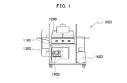
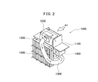
- FIG. 1 and 2 show the structure of the barbecue stove 1000 disclosed in Patent Document 1.
- FIG. FIG. 1 is a front view of the barbecue stove 1000
- FIG. 2 is a perspective view showing the barbecue stove 1000 from the rear.
- the barbecue stove 1000 includes a stove unit 1100, a hood 1200 that covers the stove unit 1100, and a propane cylinder 1500 that supplies gas to the stove unit 1100.
- BBQ stove 1000 can suppress the generation of smoke so that you can enjoy barbecue even in buildings and ordinary houses.
- a hose 1300 is attached to the hood 1200, the hose 1300 is connected to the blower unit 1400, and smoke generated in the blower unit 1400 is sucked up.
- the smoke that has been sucked out is processed by the smoke collecting device including the filter 1600.
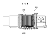
- FIG. 3 and 4 show the structure of the barbecue grill 2000 disclosed in Patent Document 2.
- FIG. 3 is a front view of the barbecue grill 2000
- FIG. 4 is a plan view showing the grill part 2100 in the barbecue grill 2000.
- the barbecue grill 2000 includes a grill unit 2100, a grill 2300 disposed in the grill unit 2100, and a propane cylinder 1500 that supplies gas to the grill unit 2100.
- a fluid circulation pipe is provided in the grill 2300 in order to prevent meat from being burnt or sticking to the grill. Then, a cooling medium is supplied to the fluid circulation pipe of the grill 2300 so that the grill 2300 can be cooled.
- JP 2014-54508 A Japanese Patent No. 4575960
- the barbecue stove 1000 of Patent Document 1 and the barbecue grill 2000 of Patent Document 2 are each devised. However, according to the study of the present inventor, those ideas actually reduce the performance of the barbecue cooking apparatus (barbecue grill), and the barbecue cooking apparatus to which those ideas are applied explodes the barbecue. It was judged that it was not popular.
- the barbecue stove 1000 of Patent Document 1 since the high temperature atmosphere (heated air) in the hood 1200 is sucked by the hose 1300, there is a problem that meat cannot be cooked in a good state.
- the baking point by the barbecue cooking apparatus is actually the sealed heating by the hood 1200, and the meat is baked deliciously by the high temperature heating sealed by the hood 1200.
- the presence or absence of hermetic heating by the hood 1200 affects the taste of meat rather than the difference between charcoal or gas fires.
- the barbecue stove 1000 of patent document 1 absorbs the high temperature atmosphere in the food
- the obstacle to the spread of barbecue is not the prevention of smoke generation, nor is the meat sticking to the grill, but propane used in a mobile barbecue cooking device (barbecue grill). I realized that it was a cylinder. Since barbecue is performed outdoors, the barbecue cooking device is inevitably mobile, which requires a propane cylinder (1500) as fuel.
- propane gas in the case of a propane cylinder, propane gas must be exhausted in the middle of the barbecue, so it is necessary to have a propane gas company fill (supplement) propane gas every time the barbecue is performed.
- propane gas company fill (supplement) propane gas Compared with the number of convenience stores, supermarkets, and home centers, there are few propane gas companies, and it is often necessary to go far to replenish propane gas.
- the price of propane gas is relatively high (compared to city gas, etc.), and propane gas replenishment depends on the capacity of the propane cylinder, even if the previous amount of propane gas remains. Because it is charged, it becomes expensive.
- the present invention has been made in view of such a point, and a main object thereof is to provide a barbecue grill that can be stably operated even at a low temperature.
- the barbecue grill according to the present invention is a barbecue grill for baking ingredients, and a gas hose connected to a cassette cylinder filled with liquefied butane mainly composed of normal butane, and a gas combusted by the gas supplied from the gas hose
- a burner unit that houses the burner, a support unit that is positioned below the burner unit and supports the burner unit, and a kiln unit that is disposed above the burner unit and covers the burner unit.
- the support part is provided with a support member for fixing the burner part, and a support part space surrounded by the support member, and the cassette cylinder is housed in the support part space, and A fan for sending air to the cassette cylinder is disposed at a location on the burner portion side in the support portion space.
- the fan is a battery-driven blower
- the support space is a closed space surrounded by the support member
- the cassette cylinder is set in a cassette cylinder unit that houses a plurality of cassette cylinders, and the gas hose is connected to the cassette cylinder unit, and above the cassette cylinder unit, The fan is arranged.
- a second fan that sends air to the cassette cylinder is disposed in the support space below the cassette cylinder.
- the support space is provided with an air guide member that sends air toward the second fan by blowing air from the fan.
- the support member surrounding the support portion space is composed of a metal plate member and a door portion.
- the support member is connected to a base part with wheels, and the base part is provided with a propane cylinder storage part for setting a propane cylinder, and the burner part includes A plurality of the gas burners are housed, and a net part on which the food is arranged is provided above the gas burner, and the net part is sealed by being covered with the kiln part.
- a thermometer indicating the internal temperature of the kiln part is arranged, a side table is connected to the burner part including the net part, and the fan and the cassette cylinder are It arrange
- the cooking method according to the present invention is a cooking method using a barbecue grill, and the barbecue grill is a baking apparatus for burning gas in a cassette cylinder filled with liquefied butane, and the step of burning gas in the barbecue grill And a step of heating the food material by the combustion, and a step of blowing the air heated by the combustion to the cassette cylinder cooled by the heat of vaporization.
- the barbecue grill includes a burner portion including a gas burner for burning the gas, and the air heated by the combustion in the blowing step is air located below the burner portion. And the heated air is applied to the cassette cylinder by the fan.
- a closed space surrounded by a support member is provided below the burner portion, the cassette cylinder is disposed in the closed space, and the heated air is supplied to the closed space. It moves in and contacts the cassette cylinder.
- the spraying step is performed by a first fan disposed above the cassette cylinder and a second fan disposed below the cassette cylinder.
- the cassette cylinder is filled with liquefied butane having n-butane as a main component, and the cassette cylinder is set in a cassette cylinder unit that stores a plurality of cassette cylinders, In the step of burning the gas of the barbecue grill, gas is supplied from the cassette cylinder unit to the barbecue grill through a gas hose.
- the cooking device is a cooking device that bakes food, and is located above the cassette cylinder unit that stores a cassette cylinder filled with liquefied butane, and vaporizes from the liquefied butane.
- a burner part for burning the burned gas, and a support part located below the burner part and supporting the burner part, and a fan is disposed between the burner part and the cassette cylinder unit. .
- the support portion is provided with a windscreen member, and the cassette cylinder unit and the fan are surrounded by the windscreen member.
- a second fan is disposed below the cassette cylinder unit.
- the fan is a suction fan that sucks ambient air, and the fan is provided with a duct that sends the sucked air to the second fan.
- the fan is a blower that blows air toward the cassette cylinder unit and sends air toward the second fan.
- the cassette cylinder box according to the present invention is a cassette cylinder box including a cassette cylinder, and includes a cassette cylinder unit that stores a cassette cylinder filled with liquefied butane, a fan positioned above the cassette cylinder unit, and the cassette cylinder.
- a housing for housing the unit, and the fan is disposed on an upper surface of the housing.
- the cassette cylinder unit is connected to a gas hose through which the gas discharged from the cassette cylinder passes, and the housing has a structure for closing the cassette cylinder unit,
- the fan is a blower that blows air located above the casing to the cassette cylinder unit, and the gas hose extends to the outside of the casing.
- the method for producing a baked product according to the present invention is a method for producing a baked product by gas combustion, a step of burning a gas burner with a gas supplied from a cassette cylinder filled with liquefied butane, The method includes a step of heating an object to be heated by combustion, and a step of blowing air heated by the combustion onto the cassette cylinder cooled by heat of vaporization.
- the air heated by the combustion is air located below the gas burner, and the heated air is applied to the cassette cylinder by a fan, A windshield member is disposed around the cassette cylinder.
- a barbecue grill is a barbecue grill for baking ingredients, and a burner unit that houses a gas burner that burns with gas supplied from a cassette cylinder filled with liquefied butane, and the burner unit And a support portion that is positioned below and supports the burner portion.
- the support part is provided with a support member for fixing the burner part and a support part space surrounded by the support member.
- the cassette cylinder is housed in the support section space, and a fan for sending air to the cassette cylinder is disposed at a location on the burner section side of the support section space.
- the fan is a battery-driven blower
- the support space is a closed space surrounded by the support member.
- the cassette cylinder is set in a cassette cylinder unit that houses a plurality of cassette cylinders, and the cassette cylinder unit is connected to the burner portion by a gas hose, and the cassette cylinder unit Above the fan, the fan is arranged.
- a second fan for sending air to the lower surface of the cassette cylinder is disposed below the cassette cylinder.
- the support space is provided with an air guide member that sends air toward the second fan by blowing air from the fan.
- the support member surrounding the support portion space is composed of a metal plate member and a door portion.
- a cooking device is a cooking device that bakes food, a cassette cylinder unit that houses a cassette cylinder, a burner unit located above the cassette cylinder unit, and a lower part of the burner unit Has a fan for blowing air to the cassette cylinder unit.
- the fan is disposed between the burner portion and the cassette cylinder unit.
- the fan is a blower that blows air onto a lower surface of the cassette cylinder unit.
- a support part that supports the burner part is provided below the burner part, and a windbreak member is provided in the support part, and the cassette cylinder unit and The fan is surrounded by the windshield member.
- a first fan is disposed above the cassette cylinder unit, and a second fan is disposed below the cassette cylinder unit.
- the first fan is a suction fan for sucking ambient air
- the first fan is provided with a duct for sending the sucked intake air to the second fan.
- a cassette cylinder box is a cassette cylinder box including a cassette cylinder, a cassette cylinder unit that houses a cassette cylinder filled with liquefied butane, a fan positioned above the cassette cylinder unit, A housing for housing the cassette cylinder unit, and the fan is disposed on an upper surface of the housing.
- the cassette cylinder unit is connected to a gas hose through which the gas discharged from the cassette cylinder passes, and the housing has a structure for closing the cassette cylinder unit,
- the fan is a blower that blows air located above the casing to the cassette cylinder unit, and the gas hose extends to the outside of the casing.
- a cassette cylinder box is a cassette cylinder box including a cassette cylinder, and includes a cassette cylinder unit that stores a cassette cylinder filled with liquefied butane, and a housing that stores the cassette cylinder unit.
- a fan for blowing air to the lower surface of the cassette cylinder is disposed inside the casing.
- a cassette cylinder box is a cassette cylinder box including a cassette cylinder, and includes a cassette cylinder unit that stores a cassette cylinder filled with liquefied butane, and a housing that stores the cassette cylinder unit.
- a heater that raises the air inside the casing is disposed inside the casing, and a fan that circulates the air heated by the heater is disposed inside the casing.
- the casing forms a sealed space, and a thermostat for controlling temperature is attached to the heater.
- the cassette cylinder is housed in the support space in the support portion that supports the burner portion that houses the gas burner, and the fan is disposed at the location on the burner portion side in the support space. . Therefore, since the air heated by the gas burner can be applied to the cassette cylinder by the fan, the temperature of the cassette cylinder cooled by the heat of vaporization can be increased by releasing butane gas. As a result, the barbecue grill using the liquefied butane cassette cylinder can be stably operated even in a low temperature environment (for example, a barbecue place in winter or at night).
- the boiling point of propane filled in the propane gas cylinder is ⁇ 42 ° C. and the vapor pressure is high, gas is emitted well even in cold regions, but in the case of a liquefied butane cassette cylinder, the boiling point of normal butane is ⁇ Since it has a low vapor pressure at 0.5 ° C, the ability to emit gas is reduced in cold places such as winter and at night.
- normal butane cassette cylinders cannot be used at temperatures below -0.5 ° C, but even at higher temperatures, the cassette cylinders are cooled by the heat of gas vaporization. Even if it comes out, the amount of gas emitted will be greatly reduced and it will not be usable for cooking and burning barbecue.
- the air heated by the gas burner is blown against the cassette cylinder cooled by the heat of vaporization, so that the temperature of the gas cylinder can be adjusted to an appropriate temperature, and therefore the amount of gas emitted is improved.
- the barbecue can be cooked and burned well even in places where the temperature is low.
- FIG. 10 is a front view showing a configuration of a barbecue grill 2000 of Patent Document 2.
- FIG. 10 is a top view showing a configuration of a barbecue grill 2000 of Patent Document 2.
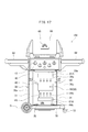
- FIG. 10 is a perspective view of the barbecue grill 3000 which this inventor examined.
- 3 is a perspective view of a cassette cylinder unit 50.
- FIG. 3 is a perspective view of a cassette cylinder 52.
- FIG. 4 It is a perspective view of a cassette cylinder unit. It is a perspective view of cassette cooker 4000. It is a cross-sectional schematic diagram explaining the heat panel of the cassette cooker 4000. It is a figure (front view) for demonstrating the barbecue grill 100 which concerns on embodiment of this invention. 4 is a perspective view for explaining a fan 21. FIG. 4 is a perspective view for explaining a fan 21. FIG. It is a figure (front view) for demonstrating the modification of the barbecue grill 100 which concerns on embodiment of this invention. It is a figure (front view) for demonstrating the modification of the barbecue grill 100 which concerns on embodiment of this invention. It is a perspective view for demonstrating the barbecue grill 100 which concerns on embodiment of this invention. It is a perspective view for demonstrating the barbecue grill 100 which concerns on embodiment of this invention.
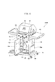
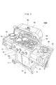
- the barbecue grill 3000 includes a burner unit 10 in which a gas burner (not shown) is housed, a support unit 30 that supports the burner unit 10, and a kiln unit 60 that covers the burner unit 10.
- a thermal power dial 15 that adjusts the amount of gas is attached to the burner unit 10.
- a grill net (not shown) for arranging and baking food (meat etc.) is arranged on the upper surface of the burner unit 10.
- Side tables 62 are attached to the sides (both sides) of the grill net.
- a thermometer 65 indicating the temperature inside the pot is attached to the kiln unit 60.
- the inside of the kiln can be steamed at a high temperature, and the temperature can be set to 200 ° C. or higher.
- This high-temperature steamed grill is the secret of the delicious barbecue.
- the support part 30 is comprised by the supporting member (30a, 30b, 30c), and the support member is the side part (side plate) 30a, the back part (back board) 30b, and the front door part (door board) 30c). Is included.
- a propane cylinder 59 can be set in the support space 20 surrounded by the support member as shown in FIG. If the gas hose 40 is connected to the propane cylinder 59 and the gas hose 40 is connected to the burner unit 10, the propane gas in the propane cylinder 59 can be supplied to the gas burner, and the gas combustion is adjusted by the operation of the thermal power dial 15. can do.
- the support part 30 (support member 31) is set on the base part 70.
- the base unit 70 is provided with a propane cylinder storage unit 75, and the professional bomb cylinder 59 can be set in the propane cylinder storage unit 75.
- a moving wheel 71 and a fixing wheel 72 are attached to the base portion 70. By the wheels 71 and 72 of the base portion 70, the barbecue grill 3000 is disposed on the ground and can be moved on the ground. Further, by turning on and off the switch of the fixing wheel 72, the barbecue grill 3000 can be moved or fixed so that the barbecue grill 3000 cannot move.
- FIG. 7 shows a state (heating state, cooking state) in which the barbecue grill 3000 is operated.
- a gas fire rises toward the grill net (foodstuff arrangement unit) 61 located above the gas burner 12.
- Ingredients (meat etc.) 90 are set on the grill 61 and can be cooked (fired) with a gas fire.
- a second grill net (food ingredient placement section) 63 is also provided inside the kiln 60, and the second grill net 63 is used to place baked ingredients or to set ingredients that do not want to be baked too much. Or the foodstuff for steaming in the kiln part 60 can be arrange
- the kitchen table (barbecue equipment) 95 such as plates and glasses can be arranged on the side table 62. Therefore, the barbecue grill 3000 itself can be used not only as a gas burner function but also as a kitchen that can provide meals. Moreover, if the gas stove 67 is mounted on the side table 62, a pot or kettle can be placed there and cooking other than grilled dishes can be performed. This gas stove 67 is also burned with the gas of the propane cylinder 59 accommodated in the support portion 30.
- the gas type barbecue grill accounts for 70-80%, and the charcoal type barbecue grill is minor. Since gas-type barbecue grills are widespread, each home where a barbecue is performed normally has a propane cylinder 59, and is familiar with and handling the propane cylinder 59. The handling of the propane cylinder 59, such as setting and opening / closing the gas stopper, is also good.
- propane (C3H8) has a boiling point of ⁇ 42.09 ° C. and a vapor pressure of 8513 (hPa, 20 ° C. (fuel energy 44.0 kg / g)). Therefore, since the boiling point of propane is low, the barbecue grill 3000 can be satisfactorily operated with the propane cylinder even when the temperature is below freezing.
- cassette cylinders are more popular than propane cylinders in Japan because they are warmer than in cold regions in North America, and often use gas fires in rooms rather than outdoors. Cassette cylinders are also convenient because they can be purchased immediately at convenience stores, supermarkets, and home centers.
- the cassette bomb is filled with liquefied butane (normal butane, n-butane). Normal butane (C4H10) has a boiling point of ⁇ 0.5 ° C. and a vapor pressure of 2213 (hPa, 20 ° C.) (fuel energy 42.8 kg / g)).
- a cassette cylinder high power (cold area) gas cylinder
- isobutane instead of normal butane
- C4H10 has a boiling point of ⁇ 11.7 ° C. and a vapor pressure of 3113 (hPa, 20 ° C.) (fuel energy 42.8 kg / g)). Since the boiling point of isobutane is ⁇ 11.7 ° C., the barbecue grill 3000 can be operated even at a temperature around the freezing point.
- isobutane cassette cylinders Even in isobutane cassette cylinders, the boiling point of isobutane is higher than that of propane, which is -42 ° C. Therefore, propane is more combustible in cold regions. Further, since the vapor pressure of isobutane is larger than the vapor pressure of normal butane, the isobutane cassette cylinder is consumed earlier than the normal butane cassette cylinder with the same capacity. Furthermore, the isobutane cassette cylinder (high power) is more expensive than the normal butane cassette cylinder (normal version), and is not economical from both viewpoints in view of increased consumption.
- propane cylinder 59 has the following problems.
- propane cylinders are not widely used, so it is often difficult to understand how to handle propane cylinders and to feel like purchasing and using propane cylinders.
- you are a staff of a specialty store such as a food stall or a restaurant, there is no problem because you are used to handling propane cylinders.
- cassette cylinders are well handled, and we know the safety and dangers. Compared with that, it adds to the desire to not handle propane cylinders.
- propane cylinders are not cheaper than cassette cylinders. Even if the unit price of the gas main body is not so much, replenishment of propane cylinders requires going to a specialty store (propane gas company) and there is a filling fee. In addition, since the propane gas company is not everywhere, there is a moving cost and time cost only for gas filling. On the other hand, since the cassette cylinder is disposable, no filling material is charged, and the cassette cylinder is sold everywhere. If a plurality of cassette cylinders are prepared, there is no problem of running out of gas. Then, even if the motivation to use the cassette cylinder is generated, the motivation to actively use the barbecue grill using the propane cylinder is hardly generated. The inventor of the present application thought that the barbecue grill could not be popular in Japan unless this vicious circle was stopped.
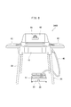
- the present inventor connected the cassette cylinder unit 50 to the barbecue grill 3500 shown in FIG. 8 and performed barbecue cooking using a normal butane cassette cylinder.
- the burner portion 10 of the barbecue grill 3500 is supported by the support bar 35.
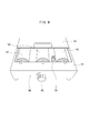
- the cassette cylinder unit 50 has a structure as shown in FIG.
- the cassette cylinder unit 50 is provided with a casing 51 that houses a cassette cylinder 52.
- a plurality of (here, three) cassette cylinders 52 can be set in the housing portion 51.
- the cassette cylinder 52 is fixed to the housing section 51 by the cover section 53, and the gas is discharged by the gas outlet section 54.
- the gas hose 40 is connected to the gas outlet 54.
- the casing 51 is provided with a gas amount adjustment dial 55. If the dial 55 is set to zero, the gas emission can be reduced to zero even when the cassette cylinder 52 is set on the casing 51. So it is safe.
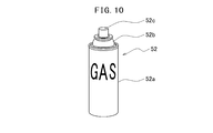
- the cassette cylinder 52 has a structure as shown in FIG.
- a liquefied gas n-butane (linear butane) or, in some cases, iso-butane (2-methylpropane)
- n-butane linear butane
- a gas outlet nozzle
- tip part 52b has a structure (specific shape including a notch part) corresponding to the setting part of a cassette stove so that it may be easy to set to a cassette stove.
- FIG. 9 the cassette cylinder unit 50 including the casing 51 is shown.
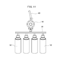
- a cassette cylinder unit using the cassette cylinder 52 may be as shown in FIG.
- the cassette cylinder unit shown in FIG. 11 includes a connecting portion 58 for connecting a plurality of cassette cylinders 52 and a gas hose connecting portion 56 attached to the connecting portion 58.
- the gas hose 40 is connected to the gas hose connection part 56.
- a gas flow rate adjustment valve may be provided in the gas hose connection portion 56.
- the inventor of the present application operated the barbecue grill 3500 shown in FIG. 8, it operated without any problems in the summer when the outside temperature was high (or in the daytime when the temperature was high).
- the outside air temperature is, for example, about 10 ° C. (or a temperature lower than 15 ° C. to 10 ° C.)
- the amount of gas from the cassette cylinder 52 decreases, making it difficult to perform a good barbecue.
- barbecue is a dish, it does not have the property of simply heating the ingredients (90). If a predetermined amount of heat cannot be input in a short period of time, a bad dish will be produced and the barbecue will fail.
- the amount of heat the amount of heat
- a part called a heat panel heat transfer member
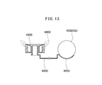
- FIG. 12 and FIG. 13 show the structure of the desktop cassette stove 4000.
- the desktop cassette stove 4000 includes a casing unit 4100 that stores the stove 4300 and a cassette cylinder storage unit 4500.
- the housing 4100 is provided with a support 4343 around the stove 4300 that supports a pan, flanks, and the like. Further, a gas output adjustment dial 4150 is provided on the cassette cylinder storage unit 4500 side of the housing unit 4100.
- the cassette cylinder 4550 (52) is set in the cassette cylinder storage unit 4500. Then, as shown in FIG. 13, when the gas fire 4400 is generated by the stove 4300, the heat is transferred to the heat transfer member 4600 to the holder (heat transfer member) 4650 that holds the bottom surface of the cassette cylinder 4550 (52). The cassette cylinder 4550 (52) is heated. In this way, the temperature reduction of the cassette cylinder due to the heat of vaporization is prevented, and the decrease in the gas ejection amount of the cassette cylinder is suppressed.
- a member such as a heat panel may be attached.
- heat transfer members 4600 and 4650 heat transfer members 4600 and 4650
- it is practical to attach such a heat panel. is not.
- the distance from the gas burner (12) of the burner unit 10 to the cassette cylinder unit 50 (cassette cylinder 52) is too far to perform heat transfer by the heat transfer member.
- the cassette cylinder 52 is not set in the burner part 10, a heat transfer member cannot be arrange
- the cassette cylinder 52 can be set in the burner unit 10 and the cassette cylinder 52 can be heated by the heat transfer member (heat panel), this time, the cassette cylinder 52 is heated too much. There is a risk that the problem will occur.
- the barbecue grill 3500 has a greater amount of heat used to execute the barbecue, and therefore tends to generate a larger amount of heat than the desktop cassette stove 4000. Then, in the case of the barbecue grill 3500, the mechanism of the heat panel that is appropriate for the desktop cassette stove 4000 may heat the cassette cylinder 52 more than necessary. Unnecessary heating of the cassette cylinder 52 is also a safety issue and should be avoided because it is undesirable.
- the inventor of the present application has come up with the idea of winding a warm or heat insulating material such as a blanket around the cassette cylinder 52 in order to prevent the temperature of the cassette cylinder 52 used in the barbecue grill 3500 from decreasing.
- the cassette cylinder 52 is not cooled by the outside air temperature, but is cooled by the heat of vaporization when the liquid changes to gas in the cassette cylinder 52 and becomes a temperature lower than the outside air temperature (or room temperature). There is no point in wrapping material like this.
- the inventor of the present application examined the use of a disposable body warmer utilizing the heat generation principle of iron oxidation reaction as a heating method without using an electrical outlet or a battery.
- the disposable body warmer reaches a temperature of about 60 ° C. (maximum temperature 63 ° C., average temperature 53 ° C., duration 10 hours), and this heats the cassette cylinder 52 too much.
- the cassette cylinder 52 is required to be stored at 40 ° C. or lower, and heating at about 60 ° C. or higher is not desirable.
- the disposable body warmer has a duration of 10 hours or more, it is considerably longer than the usage time of the barbecue grill 3500 or the usage time of the cassette cylinder 52, and thus time mismatching occurs.
- warmers other than disposable warmers (for example, warm water, warm stones, platinum catalyzed warmers, etc.) are also conceivable.
- the temperature of the cassette cylinder 52 is prevented from lowering. It is troublesome to prepare and set such a warmer. In fact, it is actually not that you want to use the barbecue grill 3500 using the cassette cylinder 52.
- the present inventor considered that the air heated by the heat generated in the burner section 10 (gas burner 12) of the barbecue grill 3500 could be used for preventing the cassette cylinder 52 from being cooled.
- the air (heated air) located immediately below the burner portion 10 of the barbecue grill 3500 was blown toward the cassette cylinder 52 with a fan (blower).
- the cassette cylinder 52 cannot be heated (cooling prevention).
- the inventor of the present application tried to conclude that the cooling of the cassette cylinder 52 could not be prevented by various studies.
- the support space 20 of the barbecue grill 3000 shown in FIG. When the cylinder unit 50 is arranged and a fan is arranged above the cassette cylinder unit 50 and below the burner unit 10, it has been found that the cooling of the cassette cylinder 52 can be reduced by blowing air from the fan.
- the support members (30a, 30b, 30c) constituting the support unit 30 function as windbreak members, and the air heated immediately below the burner unit 10 is sent to the cassette cylinder 52 by a fan (blower). It was possible to make good contact.
- the cooling drop of the cassette cylinder 52 can be suppressed, so if at least three sides (left and right side surfaces, the back surface, etc.) are closed, the flow of wind (in and out) can be stopped, It was found that a heating effect (an effect of preventing the cooling of the cassette cylinder 52) by a fan (blower) can be obtained.
- the support members (30a, 30b, 30c) of the barbecue grill 3000 shown in FIG. 5 hide the propane cylinder 59, they themselves are not windbreak members.
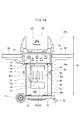
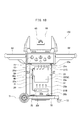
- FIG. 14 shows a configuration of the barbecue grill 100 according to the embodiment of the present invention.
- the barbecue grill (heating cooker) 100 of the present embodiment is a heating cooker (heating device, stove) that performs heating using the gas from the cassette cylinder 52, and can bake the food.
- the state (or component) of baking / cooking the food (90) is basically the same as that shown in FIG.
- An arrow 99 in FIG. 14 indicates the vertical direction (upward and downward).
- the barbecue grill 100 of this embodiment includes a burner unit 10 that houses a gas burner 12 that burns with gas, and a support unit 30 that supports the burner unit 10.
- the support part 30 is located below the burner part 10 and is composed of a support member 31.
- a kiln unit 60 that covers the burner unit 10 is provided above the burner unit 10.
- the support part 30 of the present embodiment is provided with a support member 31 for fixing the burner part 10 and a support part space 20 surrounded by the support member 31.
- the support portion space 20 is a closed space surrounded by windbreak members (30a, 30b, 30c), and is a space where the wind from the outside of the barbecue grill 100 is blocked.
- the support member 31 (30a, 30b, 30c) is a plate-like member (for example, a metal plate), and the support member 31 exhibits a windbreak function. As long as at least three sides (for example, the left and right side surfaces and the back surface) are closed, the windshield function can be provided. For example, the front portion (door portion) 30c may not exist. .
- the support member 31 is a columnar member, members (30a, 30b, 30c) having a windbreak function may be separately installed. Even a member that does not directly fix the burner unit 10 may be referred to as the support member 31 including members (30a, 30b, 30c) having a windbreak function.
- a cassette cylinder 52 is accommodated in the support space 20 of the present embodiment.
- the cassette cylinder 52 has a structure (commercially available product) as shown in FIG. 10 and is a cassette cylinder filled with liquefied butane containing normal butane as a main component. Further, the cassette cylinder 52 is set in the support space 20 in a state where it is disposed in the cassette cylinder unit 50 shown in FIG.
- the cassette cylinder unit 50 in which the cassette cylinder 52 is accommodated is connected to the burner unit 10 via the gas hose 40. That is, gas is supplied to the burner unit 10 from the cassette cylinder unit 50 through the gas hose 40.
- a normal or butane cassette cylinder is more suitable as a technical or economic advantage.
- the fan 21 is arrange
- the fan 21 is a blower (or a suction device) that sends air 25 to the cassette cylinder 52.
- the fan 21 according to the present embodiment sucks air (air heated by combustion) at a location 20 a located below the burner unit 10, and sucks the sucked air (heated air) into the cassette cylinder 52. (See arrow 25).
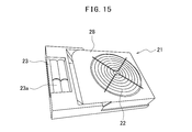
- the fan 21 shown in FIG. 15 is a battery-driven blower, and includes a blade portion 22 that sucks and blows air and a housing portion 28 that houses the blade portion 22.
- the casing unit 28 is connected to a power source unit 23 in which a battery 23a is stored.
- the battery 23a may be a dry battery or a rechargeable secondary battery.
- the fan 21 shown in FIG. 16 includes a blade portion 22 that sucks and blows air, and a housing portion 28 that houses the blade portion 22, and a power supply portion 23 is built in the housing portion 28.
- the power supply unit 23 may be of a type in which a dry battery is attached, or may be of a charge type configuration (for example, a lithium secondary battery) that can be charged like a mobile phone.
- FIG. 15, FIG. 16 is provided with the blade
- the battery 21 may be used instead of the battery type, but the battery type may be easier to carry and install. Moreover, you may operate the fan 21 using a solar cell.
- the fan 21 of the present embodiment only needs to be capable of blowing the air at the location 20a on the burner portion side of the support space 20 to the cassette cylinder unit 50.
- the output of the fan 21 is, for example, 3 W to 5 W, but is not limited to this range, and a suitable one may be adopted as appropriate.
- the dimension of the fan 21 will not be specifically limited if it can arrange
- the fan 21 is disposed above the cassette cylinder unit 50 (52), and the position of the fan 21 may be appropriately set according to the size and performance of the barbecue grill 100 to be used.
- the distance (H1) between the fan 21 and the cassette cylinder 52 is, for example, 30 cm to 40 cm.
- the distance (H2) between the fan 21 and the lower surface of the burner unit 10 is, for example, 10 cm to 40 cm (typically 20 cm to 30 cm).
- the distance (H3) between the cassette cylinder 52 and the lower surface of the burner unit 10 is, for example, 50 cm to 60 cm.
- the distance (H4) between the cassette cylinder 52 and the gas burner 12 is, for example, 70 cm to 90 cm. Note that these distances are merely examples, and if the cooling of the cassette cylinder 52 can be prevented by the capability of the fan 21, suitable installation locations and distances may be selected as appropriate.
- the fan 21 and the cassette cylinder unit 50 (52) of the present embodiment may be configured to be fixed to a part of the support portion 30 or a multistage storage member (inside the support portion space 20). For example, it may be arranged in a rack.
- a multistage storage member if the fan 21 is set in the upper stage and an opening (for example, an arrangement structure of rods and gaps) is provided under the fan 21, the air 25 from the fan 21 is supplied to the cassette cylinder. 52 will arrive directly.
- the cassette cylinder unit 50 is arranged in the middle stage or the lower stage and the distance between the stages is appropriate, the arrangement positions (for example, distances H1 to H4) of the fan 21 and the cassette cylinder unit 50 (52) can be simplified. Can be set.
- the support member 31 (support portion 30) is connected to a base portion 70 with wheels 71 and 72 attached thereto.
- the large wheel 71 is a moving wheel
- the small wheel 72 is a wheel with a stopper function.
- the base unit 70 is provided with a propane cylinder storage unit 75 for setting a propane cylinder (59), and is configured to serve as both the cassette cylinder 52 and the propane cylinder 59. If only the cassette cylinder 52 is used, the propane cylinder storage unit 75 may not be provided.
- a plurality of gas burners 12 are accommodated in the burner unit 10 of the present embodiment.
- the burner part 10 is comprised from the heat resistant material (for example, metal) which can endure the heat from the gas burner 12.
- the gas burner (main burner) 12 has a linear structure, and is arranged extending three in parallel to the ground.
- the gas burner 12 is burned by the gas supplied from the gas hose 40 connected to the cassette cylinder 52, and the heating power can be adjusted by the heating power dial 15.
- the gas burner 12 of the present embodiment has a stainless steel double tube structure, and the burner output is, for example, about 7 kW to 16 kW (preferably 8 kW to 12 kW).
- the type and output of the gas burner 12 are not particularly limited.
- a circular or annular gas burner may be used, and the gas burner output may be a small output of less than 5 kW or a larger output of 20 kW or more. It doesn't matter.
- a net unit 61 on which food (90) is arranged is provided above the gas burner 12.
- the net 61 of the present embodiment is a metal (for example, cast iron) net, and in the case of a cast iron net, a large amount of heat can be stored by its weight.
- the net portion 61 of this embodiment has a structure that gives a clear grilling like a steak of a grill house simply by placing steak meat (90) and gently pressing it from above.
- network part 61 may have a linear metal member and the arrangement structure of a clearance gap, and may have a lattice-like structure.
- a heat radiating plate for example, a heat radiating plate made of stainless steel, preferably a cross section
- a heat radiating plate having a triangular wave shape.
- the heat sink also has the role of producing great barbecue flavors, as the fat and juice that falls there evaporates at high temperatures.
- a kiln unit 60 that covers the burner unit 10 is provided.
- the kiln part 60 of the present embodiment is an aluminum casting kiln (aluminum casting kiln), has a very high heat holding power, and can keep the internal temperature constant.
- a sealed state can be made and a steaming effect can be achieved.
- the kiln part 60 is provided with a thermometer 65 that indicates the internal temperature of the kiln part, and can perform appropriate temperature management and adjustment during cooking.
- a side table 62 is connected to the side of the burner unit 10 to improve cooking workability. Further, the side table 62 has a structure that can be folded when not in use.
- the cassette cylinder unit 50 is set in the support space 20 of the barbecue grill 100 of the present embodiment.
- gas is supplied from the cassette cylinder unit 50, and the gas is burned by the gas burner 12 of the burner unit 10.
- the food (90) is heated by this combustion and cooking progresses, and the bottom portion of the burner unit 10 or the surrounding air is heated by the combustion.
- the cassette cylinder 52 As the liquefied gas in the cassette cylinder 52 is vaporized, the cassette cylinder 52 is cooled from room temperature (ambient temperature), but in the present embodiment, air heated by the fan 21 (air higher than room temperature). However, since the cassette cylinder 52 is sprayed, the cooling of the cassette cylinder 52 is alleviated.
- the surface temperature of the cassette cylinder 52 is 0.5 ° C. (the temperature stored indoors) during the operation of the gas burner 12.
- the cooling state decreased by 19.5 ° C. from 20 ° C. in FIG.
- the surface temperature of the cassette cylinder 52 became 5 ° C. (a state where the cooling was performed from 0.5 ° C. to 4.5 ° C.). That is, it has been confirmed that the operation of the fan 21 can stably operate the barbecue grill 100 that supplies gas from the cassette cylinder 52.
- the cassette cylinder 52 type barbecue grill 100 can be stably operated at night or in a cold region, so that the spread of the barbecue grill (heating cooking device) can be spread and the spread speed of the barbecue culture is increased. be able to.
- a barbecue grill device hereinating cooking device
- the barbecue grill 100 of this embodiment as long as a cassette cylinder is purchased, barbecue can be performed at any time, even at low temperatures or in the winter. Also, when barbecuing outdoors, if you buy a cassette cylinder, you can do it even without a propane cylinder.
- cassette cylinders (52, 50) are stored in the support portion space 20 in the support portion 30 that supports the burner portion 10 in which the gas burner 12 is stored.
- the fan 21 is arrange
- the barbecue grill using the liquefied butane cassette cylinder 52 can be stably operated even in a low temperature environment (for example, a barbecue place in winter or at night).
- the method of the present embodiment is very efficient because air heated by the gas burner 12 is used to prevent a temperature drop (temperature rise) of the cassette cylinder 52. That is, the heat (heated air) generated during cooking is brought into contact with the cassette cylinder 52 only by using the power-saving fan 21 instead of using an electric heater or a disposable body warmer that uses generated heat. Because no energy is used to generate heat, no heat generation costs are incurred. Therefore, it is very economical and it is very convenient because it only requires the fan 21 to operate during cooking. Further, since the cassette cylinder 52 is not directly heated but heated with heated air, the cassette cylinder 52 is not heated to an unnecessarily high temperature, which is highly advantageous in terms of safety.
- the burner unit 10 in the barbecue grill 100 of the present embodiment has a box-like shape having an open top surface and a bottom surface on the bottom surface.
- the net 61 is located on the open upper surface (opening), the gas burner 12 is located in the middle, and the bottom is located on the lower surface.
- the bottom surface of the burner unit 10 can catch fat, moisture, and the like falling from the food (90) disposed in the mesh unit 61, and can prevent the fan 21 from becoming dirty.
- the gas burner 12 heats the bottom surface (for example, a metal low plate) of the burner unit 10, and the bottom surface of the burner unit 10 is in the region (20 a) immediately below the bottom surface.
- a space 20 in which air is heated that is, the air above (directly above) the fan 21 (20a) is heated, and the heated air is blocked by the windbreak member (30a or the like) by the fan 21. Pass through the cassette cylinder 52. If the bottom surface of the burner unit 10 is not present, there is a demerit that the fan 21 (and the cassette cylinder 52) is contaminated. However, there is a mechanism / member that can trap dirt such as falling grease in the burner unit 10. For example, the bottom surface of the burner unit 10 may not be provided. In that case, the air heated by the gas burner 12 is sucked into the fan 21 by the suction force of the fan 21 and then blown onto the cassette cylinder 52.
- the windshield members (30a to 30c) since the windshield members (30a to 30c) only need to have a windshield prevention function capable of maintaining the blowing from the fan 21 to the cassette cylinder 52, the windshield members (30a to 30c) are small. There may be an opening, a gap, or something like a viewing window.
- the cross-sectional shape of the support portion 30 as viewed from above is rectangular, the windbreak function can be exhibited as long as at least three sides are closed. Further, the cross-sectional shape of the support portion 30 as viewed from above is circular (including circular, elliptical, oval, flat circular, etc.) or polygonal (in the case of hexagonal, octagonal, etc.), approximately 270 around the circumference. If the angle of about a degree is covered and closed, a windbreak function can be provided.
- windbreak members are arranged around the support bar 35, and the burner unit 10 What is necessary is just to arrange
- the fan 21 is disposed between the cassette cylinder 52 (50) under the burner unit 10 and the cassette cylinder 52 (50) cooled by the heat of vaporization is heated by the operation of the fan 21, Good.
- the cooled cassette cylinder 52 can be heated by bringing the cassette cylinder 52 close to the bottom surface of the burner unit 10 even if the fan 21 is not present.
- air is a heat insulating material, it is difficult to heat the cassette cylinder 52 not by air blowing but by heat conduction.
- the cassette cylinder 52 is heated by heat conduction without using the air blown by the fan 21, it is not preferable because the cassette cylinder 52 may be heated more than necessary.
- the heated air is applied from above the cassette cylinder 52 (50) by blowing the fan 21, but this is not limitative.
- a fan 21B is arranged below the cassette cylinder 52 (50), and air can be applied from below the cassette cylinder 52 (50) by the fan 21B.
- the first fan 21A is disposed above the cassette cylinder 52 (50), and the second fan 21B is disposed below the cassette cylinder 52 (50). Then, the upper surface (front surface) of the cassette cylinder 52 can be heated by the first fan 21A (see arrow 25a), and the lower surface (back surface) of the cassette cylinder 52 can be heated by the second fan 21B (see arrow 25b). .
- the nozzle nozzle for sucking gas from the liquefied butane
- the nozzle nozzle for sucking gas from the liquefied butane
- the nozzle nozzle for sucking gas from the liquefied butane
- the nozzle nozzle for sucking gas from the liquefied butane
- the nozzle nozzle for sucking gas from the liquefied butane
- It is set (a notch is provided in the tip 52b so that it can be set in that way). Therefore, the cooling phenomenon due to vaporization occurs more frequently on the lower surface (back surface) side of the cassette cylinder 52. Therefore, it is very effective to heat the lower surface (back surface) of the cassette cylinder 52 by the second fan 21B as in the structure shown in FIG.
- the second fan 21B (lower fan) disposed in the lower region 20b of the support portion space (closed space) 20 of the support portion 30 is separated from the burner portion 10 including the gas burner 12, but the first fan 21A ( The second fan 21 ⁇ / b> B sucks the heated air sent from the upper fan) and can blow the second fan 21 ⁇ / b> B onto the cassette cylinder 52.
- the distance (H5) between the cassette cylinder 52 and the second fan 21B is, for example, 5 cm to 15 cm. Note that these distances are merely examples, and if the cooling of the cassette cylinder 52 can be prevented by the capability of the second fan 21B, suitable installation locations and distances may be selected as appropriate.
- the surface temperature of the cassette cylinder 52 is 0.5 ° C. (during operation of the gas burner 12). 19.5 ° C.).
- the surface temperature of the cassette cylinder 52 was 7 ° C. (up 6.5 ° C.). In other words, it was confirmed that the barbecue grill 100 that supplies gas from the cassette cylinder 52 can operate stably by the operation of the first fan 21A and the second fan 21B.
- the cassette cylinder 52 cools better on the back side (and the internal nozzle extends to that side and is gasified), the cassette cylinder 52 is positively utilized by using the second fan 21B.
- the rear surface of 52 may be further heated.
- a partition plate, a member for guiding wind, and the like can be arranged so that the heated air of the first fan 21A can easily reach the second fan 21B.
- the upper fan 21 ⁇ / b> C is used as a suction fan, and is passed through a duct (air pipe) 26 to the lower fan 21 ⁇ / b> B.
- the upper fan 21 ⁇ / b> C does not apply wind to the cassette cylinder 52, and only the lower fan 21 ⁇ / b> B applies air to the cassette cylinder 52 to heat the cassette cylinder 52.
- the heated air in the upper region 20a of the support portion region 20 (location 20a adjacent to the burner portion 10) is sucked into the upper fan 21C (arrow 25c) and sent to the duct 26 (arrow 25d).
- it passes through the duct 26 (arrow 25e) is sent from the duct 26 to the lower fan 21B (arrow 25f), and is blown from the lower fan 21B to the cassette cylinder 52 (arrow 25b).
- the inventor of the present application conducted not only an experiment with a normal butane-filled cassette cylinder, but also an experiment using an isobutane-filled cassette cylinder (high-power type cassette cylinder; Super Butane Gas Gold manufactured by Toho Metal Industry Co., Ltd.).
- the temperature of the cassette cylinder (52) after 20 minutes was 4 ° C, and the gas fire at this time became considerably small and the grill temperature began to drop.
- the first fan 21A upper fan 21A
- the temperature of the cassette cylinder (52) was 13 ° C after 15 minutes.
- the temperature of the cassette cylinder (52) is 13 ° C. after 10 minutes, and at the time after 11 minutes. Since the grill temperature exceeded 300 ° C., the gas was stopped and the experiment was terminated.
- the temperature when both the first fan 21A and the second fan 21B are operated is the same as the temperature when only the first fan 21A is operated (13 ° C.). This is because the upper surface (upper surface) of the cassette cylinder 52 is actually measured, and in fact, the temperature of the lower surface of the cassette cylinder 52 is larger when both the first fan 21A and the second fan 21B are operated. This is reflected in the grill temperature (rise time).
- the barbecue grill 100 shown in FIG. 19 is a corresponding example of the configuration shown in FIG.
- a rack (multistage installation member) 29 is arranged in the support portion space 20 of the support portion 30.
- the upper stage 29a of the rack 29 has a structure in which linear members and gaps (openings) are arranged, and the fan 21 is placed on the upper surface of the upper stage 29a.
- the wind (heated air) 25 from the fan 21 is blown to the cassette cylinder 52 (50) through the gap of the upper stage 29a.
- the cassette cylinder unit 50 is placed on the middle (or lower) 29b of the rack 29.
- the middle stage (or lower stage) 29b of the rack 29 has a structure in which the linear members and the gaps are arranged. However, this stage may have no gaps.
- the barbecue grill 100 shown in FIG. 20 is a corresponding example of the configuration shown in FIG.
- a rack (multistage installation member) 29 is arranged in the support portion space 20 of the support portion 30.
- the upper stage 29a of the rack 29 has a structure in which linear members and gaps (openings) are arranged, and the upper fan 21A is placed on the upper surface of the upper stage 29a.
- the wind (heated air) 25a from the upper fan 21A is blown to the cassette cylinder 52 (50) through the gap in the upper stage 29a.
- a cassette cylinder unit 50 is placed on the middle (or lower) 29 b of the rack 29.
- the middle stage (or lower stage) 29b of the rack 29 has a structure in which linear members and gaps (openings) are arranged in the same manner as the upper stage.
- the wind (heated air) 25b from the lower fan 21B is blown to the cassette cylinder 52 (50) through the gap in the middle stage 29a.
- the barbecue grill 100 shown in FIG. 21 is a corresponding example of the configuration shown in FIG.
- a rack (multistage installation member) 29 is arranged in the support portion space 20 of the support portion 30. Further, an air guide member (duct) 26 for guiding high-temperature air is disposed.
- the upper stage 29a of the rack 29 has a structure in which linear members and gaps (openings) are arranged, and the upper fan 21A is placed on the upper surface of the upper stage 29a.
- the wind (heated air) 25a from the upper fan 21A is blown to the cassette cylinder 52 (50) through the gap in the upper stage 29a (arrow 25a).
- the air (heated air) sucked by the upper fan 21 is sent out to the air guide member (duct) 26 (arrow 25d).
- a cassette cylinder unit 50 is placed on the middle (or lower) 29 b of the rack 29.
- the middle stage (or lower stage) 29b of the rack 29 has a structure in which linear members and gaps (openings) are arranged in the same manner as the upper stage.
- the wind (heated air) 25b from the lower fan 21B is blown to the cassette cylinder 52 (50) through the gap in the middle stage 29a.
- the lower fan 21B blows ambient air onto the cassette cylinder 52 and also blows air sent from the duct 26 onto the cassette cylinder 52 (arrow 25b).
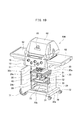
- FIG. 22 is an example of the barbecue grill 100 of the present embodiment, and shows a state where the kiln 60 is opened.
- the barbecue grill 100 of the illustrated example is different from the structure shown in FIG. 14 in the number of the thermal power dials 15 attached to the burner unit 10, but the basic configuration is the same as that of the barbecue grill 100 shown in FIG. The same.
- the gas burner 12 in the burner unit 10 when the gas burner 12 in the burner unit 10 is burned, a gas fire rises toward the grill net (food material arrangement unit) 61 located above the gas burner 12. Ingredients (meat etc.) 90 are set on the grill 61 and cooked (fired) by gas fire.
- a second grill net (food ingredient placement section) 63 is also provided inside the kiln 60, and the second grill net 63 is used to place baked ingredients or to set ingredients that do not want to be baked too much. Or the foodstuff for steaming in the kiln part 60 can be arrange
- the heated object (food material) 90 disposed in the net 61 of the present embodiment is typically a food, for example, meat (beef, pork, chicken, etc.), marine products (fish, crustaceans, mollusks). , Shellfish, seaweed, etc.), vegetables and fruits.
- meat beef, pork, chicken, etc.
- marine products fish, crustaceans, mollusks
- vegetables and fruits examples of the object to be heated include pizza, bread, baked sweet potato, and confectionery (baked confectionery, etc.). If the barbecue grill 100 of this embodiment is used, such a cooked product (baked product) can be manufactured.
- the fan 21 and the cassette cylinder unit 50 are disposed in the support space 20 below the burner section 10 to perform the above-described operation. Since it is easy to prepare a large number of unused cassette cylinders 52 to be set in the cassette cylinder unit 50, there is a concern that the fuel will run out on the way as in the case of the propane cylinder 59. It is not necessary. Even if the door part 30c of the support part 30 is opened, since the three sides are closed, the support part space 20 is in a state where the windbreak function is exhibited. Accordingly, the fan 21 and the cassette cylinder unit 50 can be operated even when the door 30c is opened.
- the cassette cylinder 52 and the cassette cylinder unit 50 including the same are not provided with the kiln unit 60. It can also be applied to various cooking devices.
- the cassette cylinder unit shown in FIG. 11 can be used as the cassette cylinder unit in addition to the cassette cylinder unit 50 shown in FIG.
- FIG. 23 shows a cassette cylinder box 150 provided with a fan 21.
- the fan 21 is a blower provided with a blade portion 22, and is disposed on the upper surface of the housing portion 129 that constitutes the cassette cylinder box 150.
- the fan 21 can blow wind to the cassette cylinder unit 50 (52).
- the cassette cylinder box 150 is composed of wind shields (130a, 130b). In the example shown in the figure, this wind shield forms the casing 129 of the cassette cylinder box 150.
- the part 130c located on one surface (for example, the front surface) of the housing portion 129 can be a door portion, a transparent member portion (glass portion, transparent plastic portion), or an open portion (opening portion). You may make it the same structure as a member (130a, 130b).
- Inside the housing 129 is a closed space 120 in which the cassette cylinder unit 50 (40) is disposed.
- the cassette cylinder unit 50 is disposed on the placement plate 129b.
- the gas hose 40 connected to the cassette cylinder unit 50 extends from the inside of the housing portion 129 to the outside.
- this cassette cylinder box 150 is disposed, for example, under the burner unit 10 of a heating cooking apparatus (barbecue grill) 3500 as shown in FIG. 8, the method of the present embodiment can be executed as it is and is convenient. is there. Further, according to the cassette cylinder box 150 of the present embodiment, the cassette cylinder 52, not the propane cylinder 59, can be used for a stove (gas combustion heating device) that uses gas in a cold region, which is very convenient. Further, the illustrated cassette cylinder box 150 may be modified so that a plurality of fans 21 are provided (see FIGS. 14 and 15 and the like). Moreover, the cassette cylinder box 150 can also be arrange
- a configuration is shown in which one fan 21 or one fan 21 is arranged above and below, but the number of fans 21 is not limited to this, and a plurality of fans 21 may be arranged.
- the heating air located immediately below the burner unit 10 is applied to the cassette cylinder 52 by the fan 21, but even if it is not directly below the burner unit 10, it is heated by the gas burner 12. Since air exists, it is possible to apply air (heated air) other than directly under the burner unit 10 to the cassette cylinder 52 by using a wind guide member such as a duct. However, since such a configuration becomes complicated, the configuration example as shown in FIG. 14 is preferable.
- thermometer may be arranged in the cassette cylinder 52 (the cassette cylinder unit 50 and the cassette cylinder box 150) so that the temperature of the cassette cylinder 52 can be displayed in real time. It is not preferable to heat the cassette cylinder 52 with an electric heater because electric power is wasted and the temperature tends to become high. However, using the method of the present embodiment, the cassette cylinder 52 is heated while assisting. However, it is not until the temperature is controlled with an electric heater. This is because such temperature control is auxiliary heating, so that power consumption is small, and it is preferable to actively control the temperature of the cassette cylinder 52.
- the cassette cylinder box 150 shown in FIG. 23 may be modified as follows.
- the internal space 120 of the housing portion 129 shown in FIG. 23 is a closed space (closed space, sealed space), and a heater (heating device) is provided in the housing portion 129 (internal space 120).
- a heater heating device
- the air (internal air) heated by the heater (heating device) is internally circulated by a fan (blower) disposed in the interior (internal space 120) of the housing portion 129, and thereby circulated.
- the cooled cassette cylinder 52 (50) can be heated by the heated air.
- a temperature sensing switch is provided, and temperature control inside the housing portion 129 (internal space 120) is executed.
- the heating switch is turned on at the lower limit temperature (for example, 20 ° C. or lower), and the heating switch is turned off at the upper limit temperature (for example, 30 ° C.). In this way, it is possible to continue heating the cassette cylinder 52 safely.
- the present inventor conducted an experiment on a cassette cylinder box including the cassette cylinder unit 50 in which the cassette cylinder 52 is set.
- the cassette cylinder box 150 shown in FIG. 23 has substantially the same configuration as the support portion 30 of the barbecue grill (heating cooker) 100 of the present embodiment shown in FIG. Heated air can be sent by the fan (22) to the closed space 120 (or substantially closed space) constituted by the shade portions (130a, 130b). Accordingly, since the heated air is sent to the closed space 120 by the fan 22 and the cooled cassette cylinder 52 (50) can be heated by the heat of the heated air, the experiment of the barbecue grill 100 shown in FIG. Similar results (or substantially the same results, although changing depending on conditions) are obtained.
- the inventor of the present application also has the effect of the enclosed space 120 configured by the wind shield portions (130 a, 130 b) (or the wind shield portion ( The effect when there is no closed space 120 composed of 130a and 130b) and the effect when a heater is present in the closed space 120 were examined through experiments.
- Example 1 First, as an example (Example 1) in which the closed space 120 constituted by the windbreak portions (130a, 130b) does not exist, the cassette cylinder unit 50 is connected to the burner portion 10 with the cassette cylinder unit 50 shown in FIG. A combustion experiment (temperature change experiment of the gas cylinder 52) was performed next to the support part 30 having the configuration shown in FIG. 1 (that is, outside the support part space (closed space) 20).
- the cassette cylinder unit 50 used in the experiment is the one shown in FIG. 9, which accommodates three cassette cylinders 52, and the surface temperature of the lower surface of each cassette cylinder 52 was measured with a thermometer. In addition, the outside air temperature was also measured with a thermometer.
- Example 1 the outside air temperature at ignition (0 minutes) was 24 ° C., and the temperature (bottom surface temperature) of the cassette cylinder 52 was 24 ° C. Then, at 5 minutes after ignition (outside air temperature was 24 ° C.), the temperature (lower surface temperature) of the cassette cylinder 52 was 24 ° C. as at the start. However, at 10 minutes after ignition (outside temperature was 24 ° C.), the temperature of the cassette cylinder 52 (lower surface temperature) was 22 ° C. After this (after 10 minutes), the temperature gradually decreases, and after 15 minutes from ignition (outside air temperature is 24 ° C.), the temperature of the cassette cylinder 52 (lower surface temperature) is 18 ° C. became.
- Example 2 Next, the inventor of the present application placed a cassette cylinder unit 50 in a state where the cassette cylinder unit 50 is arranged beside the support portion 30 having the configuration shown in FIG. A fan (second fan 21 ⁇ / b> B) is arranged from below the unit 50, and wind (outside air) is blown from below to the lower surface of the cassette cylinder 52.
- the wind (outside air) here is not air heated by the grill unit 10 but air having the same temperature as the outside air temperature (natural air).
- the rack in other words, the mounting structure of the cassette cylinder 52 (or the cassette cylinder unit 50)) 29 having the configuration shown in FIG. 20 is installed outside (side) the support section 30.
- the experiment was conducted with the lower fan (second fan) 21B disposed below the cassette cylinder unit 50 without the upper fan (first fan) 21A.
- Example 2 the outside air temperature at the time of ignition (0 minutes) was 23 ° C., and the temperature (bottom surface temperature) of the cassette cylinder 52 was 23 ° C. Then, at 5 minutes after ignition, the temperature of the cassette cylinder 52 was 21 ° C., almost the same as at the start. At 10 minutes after ignition, the temperature of the cassette cylinder 52 was 20 ° C. And 15 minutes after ignition, the temperature of the cassette cylinder 52 was 19 ° C. Then, 20 minutes after the ignition, the temperature of the cassette cylinder 52 was 19 ° C. Compared with Example 1, the temperature drop of the cassette cylinder 52 could be considerably moderated by applying the wind from the lower fan 21B to the cassette cylinder 52 (lower surface). And there was no noticeable decline in firepower.
- Example 2 if the outside air temperature is sufficiently high (for example, 20 ° C. or higher), the heat source (heat of the burner unit 10 or heat of a specially arranged heater) is used for heating. It has been found that the cassette cylinder 52 can be stably vaporized by using outside air without using air. However, when the outside air temperature is less than 15 ° C., it is expected that it is difficult to obtain stable combustion of the cassette cylinder 52.
- the heat source heat of the burner unit 10 or heat of a specially arranged heater
- the inventor of the present application arranged the sealed cassette cylinder unit 50 beside the support portion 30 having the configuration shown in FIG. 14 (that is, outside the support portion space (closed space) 20). That is, in the configuration shown in FIG. 23, the fan 22 is not provided.
- the cassette cylinder unit 50 is arranged in a cardboard (box) to be hermetically sealed. A heater and a thermostat were placed in this cardboard (box), and heating by the heater (heating of the air inside the cardboard) was performed, and the thermostat set temperature was set to 26 ° C. And there are no fans in the box. The temperature inside the box was measured at a mid-high temperature inside the box.
- the temperature inside the box at the time of ignition (0 minutes) was 23 ° C. (the outside temperature was 22 ° C.), and the temperature (bottom surface temperature) of the cassette cylinder 52 was 23 ° C.
- the temperature in the box was 28 ° C.
- the temperatures of the cassette cylinders 52 were 18 ° C., 19 ° C., and 20 ° C., respectively.
- the temperature inside the box was 35 ° C.
- the temperature of the cassette cylinder 52 was 12 ° C., 13 ° C., and 16 ° C., respectively.
- the temperature inside the box was 39 ° C., and the temperature of the cassette cylinder 52 was 9 ° C./9° C./13° C.
- the experiment for the longer time was stopped because the firepower was bad.
- Example 3 From the results of this experiment (Example 3), it is understood that the temperature of the cassette cylinder 52 rapidly decreases if the air in the box is not rotated by a fan even though the box is heated by a heater. It was. This is because the circulation of air in the box is extremely poor, and the temperature in the middle of the box increases steadily, but the temperature of the cassette cylinder 52 drops more drastically than when exposed to the outside, and therefore the cassette cylinder 52 The stable combustion of was not obtained.
- Example 4 Next, the inventor of the present application conducted an experiment in which the fan was placed in the box and the air in the box was circulated in the experiment of Example 3.
- the fan was arranged beside the cassette cylinder unit 50, not below the cassette cylinder unit 50. That is, in the configuration shown in FIG. 23, corrugated cardboard is used for the box, the cassette cylinder unit 50 is disposed in the box, and the heater, thermostat, and fan are disposed in a sealed state.
- the set temperature of the thermostat was 26 ° C. as in Example 3.
- the temperature inside the box at the time of ignition (0 minutes) was 23 ° C. (the outside temperature was 21 ° C.), and the temperature (bottom surface temperature) of the cassette cylinder 52 was 22 ° C.
- the temperature inside the box was 25 ° C.
- the temperatures of the cassette cylinders 52 were 22 ° C., 22 ° C., and 22 ° C., respectively.
- the temperature inside the box was 24 ° C.
- the temperature of the cassette cylinder 52 was 18 ° C., 18 ° C., and 18 ° C., respectively.
- the temperature inside the box was 24 ° C.
- the temperature of the cassette cylinder 52 was 16 ° C./18° C./17° C.
- Example 4 From the results of this experiment (Example 4), it was found that when the air in the box was circulated by the fan, the heat of the heater was uniformly distributed in the box and the temperature difference in the box was almost eliminated. Then, it was found that the temperature drop of the cassette cylinder 52 was moderate, and the cassette cylinder 52 was heated by the warm air generated by the heat of the heater (and the warm air circulating by the fan).
- Example 4 it is possible to further stabilize the temperature of the cassette cylinder 52 by increasing the temperature of the thermostat.
- This system (configuration in which a heater and a fan are arranged in a sealed box) can vaporize gas stably without being influenced by the outside air temperature.
- the cassette cylinder 52 is prohibited from being used in a high temperature environment of 40 ° C. or higher, it is presumed that a sufficiently stable combustion effect can be obtained by maintaining the internal temperature of 30 ° C. or lower.
Landscapes
- Engineering & Computer Science (AREA)
- Food Science & Technology (AREA)
- Chemical & Material Sciences (AREA)
- Combustion & Propulsion (AREA)
- Mechanical Engineering (AREA)
- General Engineering & Computer Science (AREA)
- Health & Medical Sciences (AREA)
- Nutrition Science (AREA)
- Life Sciences & Earth Sciences (AREA)
- Polymers & Plastics (AREA)
- Baking, Grill, Roasting (AREA)
Abstract
Priority Applications (5)
| Application Number | Priority Date | Filing Date | Title |
|---|---|---|---|
| KR1020167029402A KR20170084989A (ko) | 2015-12-29 | 2016-06-06 | 바비큐 그릴 및 바비큐 그릴을 이용한 조리방법 |
| US15/304,363 US20180084945A1 (en) | 2015-12-29 | 2016-06-06 | Barbecue grill and cooking method using barbecue grill |
| CA2946134A CA2946134C (fr) | 2015-12-29 | 2016-06-06 | Grille de barbecue et methode de cuisson sur grille de barbecue |
| CN201621371964.8U CN207384133U (zh) | 2015-12-29 | 2016-12-14 | 烧烤架 |
| CN201611153418.1A CN106491001A (zh) | 2015-12-29 | 2016-12-14 | 烧烤架以及使用烧烤架的烹调方法 |
Applications Claiming Priority (2)
| Application Number | Priority Date | Filing Date | Title |
|---|---|---|---|
| JP2015257682A JP5980406B1 (ja) | 2015-12-29 | 2015-12-29 | バーベキューグリルおよびバーベキューグリルを用いた調理方法 |
| JP2015-257682 | 2015-12-29 |
Publications (1)
| Publication Number | Publication Date |
|---|---|
| WO2017115478A1 true WO2017115478A1 (fr) | 2017-07-06 |
Family
ID=56820015
Family Applications (1)
| Application Number | Title | Priority Date | Filing Date |
|---|---|---|---|
| PCT/JP2016/066814 Ceased WO2017115478A1 (fr) | 2015-12-29 | 2016-06-06 | Barbecue et procédé de cuisson utilisant le barbecue |
Country Status (5)
| Country | Link |
|---|---|
| US (1) | US20180084945A1 (fr) |
| JP (1) | JP5980406B1 (fr) |
| KR (1) | KR20170084989A (fr) |
| CN (1) | CN207384133U (fr) |
| WO (1) | WO2017115478A1 (fr) |
Families Citing this family (8)
| Publication number | Priority date | Publication date | Assignee | Title |
|---|---|---|---|---|
| KR200484689Y1 (ko) * | 2016-12-24 | 2017-10-16 | 이진수 | 엘피지를 이용한 캠핑용 버너 |
| US20190075968A1 (en) * | 2017-09-12 | 2019-03-14 | Ooki, Llc | Modular firebox for cooking grill |
| CN109363525A (zh) * | 2018-12-12 | 2019-02-22 | 陈得海 | 烧烤炉 |
| USD923382S1 (en) | 2018-12-21 | 2021-06-29 | The Boltz Group, LLC | Five burner grill |
| KR102238088B1 (ko) * | 2020-03-04 | 2021-04-09 | 주식회사 플랭 | 화염 제초기 |
| US11767980B2 (en) * | 2020-11-03 | 2023-09-26 | Dansons Us, Llc | Longitudinal burn pot assembly and improved air flow system |
| US12385639B2 (en) * | 2022-07-07 | 2025-08-12 | 2731848 Ontario Inc. | Cigar lighter with enclosed burn area |
| DE102022003028A1 (de) * | 2022-08-18 | 2024-02-29 | Truma Gerätetechnik GmbH & Co. KG | Funktionseinheit |
Citations (4)
| Publication number | Priority date | Publication date | Assignee | Title |
|---|---|---|---|---|
| JPH09152132A (ja) * | 1995-11-30 | 1997-06-10 | Zojirushi Corp | 加温体の位置決め・落下防止構造 |
| JPH09222222A (ja) * | 1996-02-15 | 1997-08-26 | Shinfuji Burner Kk | ボンベ加熱装置 |
| JP2003095609A (ja) * | 2001-09-25 | 2003-04-03 | Matsushita Electric Works Ltd | 改質ガス生成システム |
| US20080141997A1 (en) * | 2006-12-18 | 2008-06-19 | Chaim Druin | Outdoor gas barbecue grill with an electric self-cleaning unit |
Family Cites Families (19)
| Publication number | Priority date | Publication date | Assignee | Title |
|---|---|---|---|---|
| US2445059A (en) * | 1945-12-10 | 1948-07-13 | Phillips Petroleum Co | Heater |
| GB772458A (en) * | 1954-08-14 | 1957-04-10 | Percy Escott North | An improved protective device for gas cylinders |
| US4106914A (en) * | 1977-05-09 | 1978-08-15 | Kun Ming Liu | Safety fuel gas and apparatus for generating the same |
| US4284058A (en) * | 1979-06-04 | 1981-08-18 | Conceptual Factors, Inc. | Backpacker's stove apparatus |
| US4369760A (en) * | 1980-09-22 | 1983-01-25 | Northland Aluminum Products, Inc. | Portable oven air circulator |
| US5337654A (en) * | 1992-04-29 | 1994-08-16 | Northland Aluminum Products, Inc. | Portable oven air circulator |
| EP0805302A1 (fr) * | 1996-05-03 | 1997-11-05 | WALTER TOSTO SERBATOI S.p.A. | Distributeur de gaz combustible provenant d'une pluralité de cartouches de gaz liquéfié |
| JP3892958B2 (ja) * | 1997-12-02 | 2007-03-14 | ジャパン・エア・ガシズ株式会社 | ガス容器用の加熱装置 |
| DE69936055T2 (de) * | 1998-07-02 | 2007-12-13 | Best, Willie H. | Erhitzungs-einheit und kochgerät |
| AUPP600298A0 (en) * | 1998-09-17 | 1998-10-08 | Dartnall, Jonathan Kim | Heat transfer system |
| AUPR399001A0 (en) * | 2001-03-27 | 2001-04-26 | Silverbrook Research Pty. Ltd. | An apparatus and method(ART104) |
| KR200345555Y1 (ko) * | 2003-12-29 | 2004-03-24 | 박광배 | 휴대용 가스레인지의 화력 강화장치 |
| CN101196272B (zh) * | 2006-12-08 | 2015-08-19 | 碧氢科技开发股份有限公司 | 便携式流体输送系统及套件 |
| US20110041830A1 (en) * | 2009-08-21 | 2011-02-24 | Mahloch Gregory A | Convection Oven Fan |
| US20110219958A1 (en) * | 2010-03-10 | 2011-09-15 | Ross Edward Noble | Multi-functional food preparation devices |
| US8894478B1 (en) * | 2012-01-06 | 2014-11-25 | Woodrow Stillwagon | Environmental improvement system |
| US9504354B1 (en) * | 2013-08-23 | 2016-11-29 | Salvador Ficarra | Combination barbecue grill and smoker apparatus |
| EP2944861A1 (fr) * | 2014-05-13 | 2015-11-18 | Linde Aktiengesellschaft | Convection générée par sa propre énergie pour des évaporateurs chauffés à air |
| WO2016053429A1 (fr) * | 2014-10-03 | 2016-04-07 | Welles Clifford G | Système de chauffage catalytique et procédé de chauffage de boisson ou d'aliment |
-
2015
- 2015-12-29 JP JP2015257682A patent/JP5980406B1/ja not_active Expired - Fee Related
-
2016
- 2016-06-06 WO PCT/JP2016/066814 patent/WO2017115478A1/fr not_active Ceased
- 2016-06-06 KR KR1020167029402A patent/KR20170084989A/ko not_active Ceased
- 2016-06-06 US US15/304,363 patent/US20180084945A1/en not_active Abandoned
- 2016-12-14 CN CN201621371964.8U patent/CN207384133U/zh not_active Expired - Fee Related
Patent Citations (4)
| Publication number | Priority date | Publication date | Assignee | Title |
|---|---|---|---|---|
| JPH09152132A (ja) * | 1995-11-30 | 1997-06-10 | Zojirushi Corp | 加温体の位置決め・落下防止構造 |
| JPH09222222A (ja) * | 1996-02-15 | 1997-08-26 | Shinfuji Burner Kk | ボンベ加熱装置 |
| JP2003095609A (ja) * | 2001-09-25 | 2003-04-03 | Matsushita Electric Works Ltd | 改質ガス生成システム |
| US20080141997A1 (en) * | 2006-12-18 | 2008-06-19 | Chaim Druin | Outdoor gas barbecue grill with an electric self-cleaning unit |
Also Published As
| Publication number | Publication date |
|---|---|
| JP2017119047A (ja) | 2017-07-06 |
| KR20170084989A (ko) | 2017-07-21 |
| JP5980406B1 (ja) | 2016-08-31 |
| US20180084945A1 (en) | 2018-03-29 |
| CN207384133U (zh) | 2018-05-22 |
Similar Documents
| Publication | Publication Date | Title |
|---|---|---|
| JP5980406B1 (ja) | バーベキューグリルおよびバーベキューグリルを用いた調理方法 | |
| AU2013290471B2 (en) | Refractory cooking devices | |
| CN106211752B (zh) | 带有保温柜的烧烤装置 | |
| US8061348B1 (en) | Fireplace oven | |
| AU2014200984B2 (en) | A Barbeque | |
| TWI758292B (zh) | 加熱調理器 | |
| US9237827B2 (en) | Cooking appliance of the grill or barbecue type | |
| US8381638B1 (en) | Grill configuration having a forced air curtain and its associated method of operation | |
| KR102236131B1 (ko) | 휴대용 바비큐 조리기구 | |
| CA2946134C (fr) | Grille de barbecue et methode de cuisson sur grille de barbecue | |
| KR200371963Y1 (ko) | 조리기구판 | |
| CN213146639U (zh) | 一种户外多功能柴火炉 | |
| US20130161315A1 (en) | Infrared Cooker | |
| CN210276932U (zh) | 一种便携式燃气烤炉 | |
| CN205597785U (zh) | 烧烤炉底座 | |
| CN204683379U (zh) | 一种户外铁板烧炉具 | |
| JP2887309B2 (ja) | 調理器 | |
| CN209678287U (zh) | 一种多功能户外木炭便携炉 | |
| CN209966167U (zh) | 一种多功能烤箱 | |
| KR20230166426A (ko) | 취사 겸용 난로 | |
| ES2835224T3 (es) | Parrilla de gas y método de asado a la parrilla | |
| CN204909153U (zh) | 一种多功能烧烤炉 | |
| CN220778140U (zh) | 一种隔热防烫烧炭引火保火炉 | |
| CN210408160U (zh) | 一种无烟烧烤炉 | |
| CN220675838U (zh) | 一种燃烧木柴的烧烤炉 |
Legal Events
| Date | Code | Title | Description |
|---|---|---|---|
| WWE | Wipo information: entry into national phase |
Ref document number: 15304363 Country of ref document: US |
|
| WWE | Wipo information: entry into national phase |
Ref document number: 2946134 Country of ref document: CA |
|
| ENP | Entry into the national phase |
Ref document number: 20167029402 Country of ref document: KR Kind code of ref document: A |
|
| 121 | Ep: the epo has been informed by wipo that ep was designated in this application |
Ref document number: 16881458 Country of ref document: EP Kind code of ref document: A1 |
|
| NENP | Non-entry into the national phase |
Ref country code: DE |
|
| 122 | Ep: pct application non-entry in european phase |
Ref document number: 16881458 Country of ref document: EP Kind code of ref document: A1 |
|
| NENP | Non-entry into the national phase |
Ref country code: JP |