WO2017134736A1 - Structure de raccordement de tuyau de système d'extinction d'incendie et son procédé de raccordement - Google Patents
Structure de raccordement de tuyau de système d'extinction d'incendie et son procédé de raccordement Download PDFInfo
- Publication number
- WO2017134736A1 WO2017134736A1 PCT/JP2016/052987 JP2016052987W WO2017134736A1 WO 2017134736 A1 WO2017134736 A1 WO 2017134736A1 JP 2016052987 W JP2016052987 W JP 2016052987W WO 2017134736 A1 WO2017134736 A1 WO 2017134736A1
- Authority
- WO
- WIPO (PCT)
- Prior art keywords
- female
- piping
- male
- fire extinguishing
- connection structure
- Prior art date
- Legal status (The legal status is an assumption and is not a legal conclusion. Google has not performed a legal analysis and makes no representation as to the accuracy of the status listed.)
- Ceased
Links
Images


Classifications
-
- A—HUMAN NECESSITIES
- A62—LIFE-SAVING; FIRE-FIGHTING
- A62C—FIRE-FIGHTING
- A62C35/00—Permanently-installed equipment
- A62C35/58—Pipe-line systems
- A62C35/68—Details, e.g. of pipes or valve systems
Definitions
- the present invention relates to the structure of a pipe joint, and more particularly to the structure of a pipe joint used for fire extinguishing equipment piping.
- Sprinkler equipment is installed in buildings, shopping centers, etc., which store water for extinguishing fire, sprinkler heads for spraying water, piping for fire extinguishing equipment connecting water tanks and sprinkler heads, water for water tanks Is composed of equipment such as a pump for feeding water to the sprinkler head. Fire extinguishing equipment piping is filled with pressurized water.
- the sprinkler head is mainly installed at a high position such as directly below the roof in a building without a ceiling surface or a ceiling such as a warehouse. Therefore, the fire extinguishing equipment piping that sends water from the water storage tank to the sprinkler head is laid at a high position in the room. Therefore, the construction of fire extinguishing equipment piping was a work at a high place where the foot was unstable, and the burden on the worker was great.
- the fire-extinguishing equipment pipe is connected to the sprinkler head via a flexible pipe such as a metal flexible pipe or a resin pipe by branching the main pipe leading to the water storage tank with a multi-joint joint.
- the connection structure between the flexible tube and the multi-neck joint is a screw structure. After a seal tape is wound around the threaded portion, it is screwed in with a predetermined torque so that the seal tape bites into the threads and seals. Sex is obtained.
- connection part has been fastened with an oil pen etc. so that the operator can check whether the pipe connection point is securely fastened. Some sites are marked.
- the present invention provides the following fire extinguishing equipment piping connection structure. That is, a pipe installed in a fire extinguishing system, which is tubular and has a female pipe member with a female screw inside the end, and a female pipe member with a female pipe member that is tubular and outside the end.
- a water-stopping member is installed between the inner peripheral surfaces of the fire extinguisher and the contact surface that contacts the end surface of the female piping member when the fastening of the male screw and the female screw is completed is installed on the outer periphery of the male piping member It is a connection structure of equipment piping.
- the female piping member with the female screw and the male piping member with the male screw have a conventional fastening structure with screws, and the outer peripheral surface of the cylindrical connecting portion provided in the male piping member and the female piping
- the water stop member was installed between the inner peripheral surfaces of the member.
- the end face of the female piping member is screwed into contact with the contact surface installed on the outer periphery of the male piping member, so that the worker can insert the male screw and the female screw. It can be recognized that the screw is sufficiently screwed and is in a fastened state.
- the inspector who confirms the connection location of the fire-extinguishing equipment piping also recognizes the fastening state of the male screw and the female screw by checking whether the end surface of the female piping member is in contact with the contact surface of the male piping member. it can.
- the male piping member can be idled with respect to the connecting portion, and when a long pipe is connected to the connecting portion in advance, only the male piping member is rotated without rotating the connecting portion, and the male screw and the female screw are rotated. Can be concluded.
- the step part installed in the edge part of the male piping member, and the step part installed in the edge part of the female piping member, and the indicator which can be detachably engaged with two step parts Can be configured.
- the indicator can be engaged with the step portion when the male screw and the female screw are fastened and the water-stopping member is properly crushed. When the fastening of the screw is insufficient, the indicator is not engaged with the step portion because the two step portions are separated from each other.
- the water stop member functions to maintain a sealed state, and it can be easily confirmed that the screw is in a fastened state.
- a locking step is engraved in the vicinity of the male screw, and there is a stopper inserted through the side of the female piping member in the state where the male screw and the female screw are fastened. is set up.
- the stopper engages with the locking step at the tip of the male screw.
- the stopper and the male piping member can be configured integrally. This eliminates the work of attaching the stopper to the male pipe member in the pipe connection work.
- connection method using the above-mentioned fire extinguishing equipment piping connection structure is to connect the connecting portion protruding from the male piping member to the connecting port of the female piping member having the female screw, and connect to the inner peripheral seal surface of the female piping member From the step of inserting the outer peripheral seal surface of the part, and the step of rotating the male pipe member that idles with respect to the connecting part, screwing the male screw and the female screw, and engaging the stopper with the locking step part become. Moreover, it can confirm easily that it is a connection completion state by including the process of attaching an indicator after these processes.
- connection structure of equipment piping and the connection method thereof can be realized.
- FIG. 1 shows the installation state of fire extinguishing equipment piping.
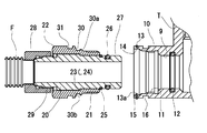
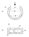
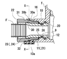
- XX sectional drawing of FIG. Sectional drawing before the connection of FIG. (A) is an external view of an indicator.
- (B) is the external view seen from the arrow A direction of (a).
- connection structure between the multi-joint joint T and the flexible pipe F having the connection structure of the fire extinguishing equipment pipe of the present invention will be described with reference to FIGS.
- connection port 10 installed on the side surface of the multi-joint joint T is connected to a metal flexible pipe F.
- a sprinkler head S is connected to the other end of the flexible pipe F.
- the upper end of the multi-joint joint T is connected to a water supply pipe P, and the water supply pipe P is connected to a water supply device such as a pump or a water source (not shown).
- connection port 10 is the female piping member of the present invention.
- An O-ring 12 is installed behind the female screw 11 as a water stop member. Between the female screw 11 and the O-ring 12, a seal surface 9 is in contact with an O-ring 26 installed on a male pipe member 22 described later.
- a lock ring 13 is installed in front of the female screw 11, and the lock ring 13 is installed in an annular groove 14 formed on the outer peripheral surface of the connection port 10.
- the lock ring 13 is made of an elastic material.
- the lock ring 13 is a stopper that prevents loosening of the female screw 11 and a male screw 21 described later.
- the lock ring 13 has a ring shape having a notch, and includes a lock portion 13a having one end bent toward the center.
- the lock portion 13a is inserted into a hole 15 extending from the annular groove 14 to the inner peripheral side of the connection port 10, and protrudes inward from the inner peripheral surface of the connection port when the lock ring 13 is fitted in the annular groove 14. It is in a state. Further, since the depth dimension of the annular groove 14 is smaller than the thickness dimension of the lock ring 13, the lock ring 13 can be easily removed from the annular groove 14 by using a pointed tool or a flat-blade screwdriver.
- a stepped portion 16 is installed behind the annular groove 14.
- the step portion 16 is a groove formed in an annular shape.
- a male piping member 22 having a male screw 21 is installed outside the connecting portion 20.
- the male piping member 22 has a tubular shape, and a male screw 21 is formed on one end side (right side in the figure).
- the step 23 on the outer peripheral surface of the connecting portion 20 and the step 24 inside the male piping member 22 are locked, and the end surface on the male screw 21 side of the male piping member 22 is engaged by a retaining ring 25 installed on the outer periphery of the connecting portion 20. It has stopped.
- the connecting portion 20 is incorporated in the male piping member 22, and the male piping member 22 can idle with respect to the connecting portion 20.
- the end of the connecting portion 20 on the side where the retaining ring 25 is installed protrudes from the male pipe member 22, and an O-ring 26 is installed on the outer peripheral surface as a water stop member.
- the front end side of the O-ring 26 is a seal surface 27 with which the O-ring 12 installed inside the connection port 10 contacts. Further, by forming the tip of the connecting portion 20 in a curved surface or a tapered shape, the O-ring 12 is not damaged at the tip of the communicating portion 20 when the connecting portion 20 is inserted into the connection port 10.
- connection portion 20 An end (left end in the figure) of the connecting portion 20 opposite to the side where the retaining ring 25 is installed is a connecting portion with the flexible pipe F.
- the connecting portion 20 and the flexible pipe F are connected via a nut 28.
- the nut 28 and the flexible pipe F are fixed by welding or the like.
- the female screw of the nut 28 and the male screw 29 of the connecting portion 20 are detachable.
- the aforementioned male screw 21 is installed on one end side (right side in the figure) on the outer periphery of the male piping member 22.
- An annular groove 30 is formed on the other end side of the male screw 21.
- the groove 30 accommodates the tip of the lock portion 13 a of the lock ring 13.
- the groove 30 functions as a locking step portion where the stopper is locked.
- a slope 30 a is provided between the groove 30 and the male screw 21.
- An edge of the groove 30 opposite to the side where the inclined surface 30a is installed is a contact surface 30b with which the end face of the connection port 10 abuts when the male screw 21 and the female screw 11 are fastened.
- a step portion 31 is installed on the other end side of the groove 30 of the male pipe member 22.
- the step portion 31 is a groove that is engraved in an annular shape.
- An indicator 32 is engaged with the step portion 31 and the step portion 16 on the connection port 10 side.
- the indicator 32 has a C-shape as shown in FIG. 5 and is made of an elastic member such as resin or metal.
- Protrusions 33 and 33 that engage with the step portions 16 and 31 are provided inside the indicator 32.
- the protrusion 33 extends toward the center of the indicator 32, and a thin portion 34 is formed between the protrusions 33 and 33.
- a plurality of notches 35 are provided on the inner edge of the protrusion 33, and the indicator 32 is easily elastically deformed.
- the thin part 34 is missing at both ends of the indicator 32. Accordingly, when attaching the indicator 2, the protrusions 33 and 33 are easily engaged with the stepped portions 16 and 31.
- the indicator 32 is used to indicate that the connection portion between the flexible pipe F and the multi-joint joint T is securely fastened.
- the indicator 32 can be engaged with the step portions 16 and 31 when the male screw 21 and the female screw 11 are screwed together and the contact surface 30b of the male joint member 22 and the end surface of the connection port 10 are in contact with each other. If the male screw 21 and the female screw 11 are not sufficiently screwed together, the step 16 and the step 31 are wider than the protrusion 33 and 33, so the protrusion 33 and 33 and the step 16 and 31 are engaged. Do not match. In this case, the male piping member 22 is further rotated in the direction in which the screw is tightened to bring the contact surface 30 b into contact with the end surface of the connection port 10, and then the indicator 32 is attached to the steps 16 and 31.
- the indicator 32 is colored with a conspicuous fluorescent color, it is easy to visually confirm the connection state between the multi-joint T and the flexible pipe F installed at a high position in the building.
- the multi-joint joint T connected to the water supply pipe P installed in the upper part of the room has a plurality of connection ports 10 on the side surface.
- the flexible pipe F is in a state of being connected in advance to the connecting portion 20 via the nut 28.
- the male pipe member 22 is rotated and the male screw 21 and the female screw 11 are screwed together.
- the connecting portion 20 gradually moves to the back of the connection port 10 so that the O-rings 11 and 26 and the seal surfaces 27 and 9 come into contact with each other.
- the connecting portion 20 since the male piping member 22 idles with respect to the connecting portion 20, the connecting portion 20 does not rotate when the male screw 21 and the female screw 11 are screwed together, and the O-rings 11 and 26 are twisted by rotation by screwing. Is prevented. Further, the flexible pipe F connected to the other end side of the connecting portion 20 is not twisted by the rotation due to screwing.
- the tip of the lock portion 13a of the lock ring 13 is elastically deformed outward along the inclined surface 30a of the male piping member 22 and gets over the inclined surface 30a to enter the inside of the groove 30. Move to.
- the lock portion 13a and the edge of the groove 30 interfere with each other to prevent the female screw 11 from rotating in the loosening direction.
- the male pipe member 22 is rotated until the end face of the connection port 10 contacts the contact surface 30b of the male pipe member 22, the male screw 21 and the female screw 11 are fastened, and then the indicator 32 is attached.
- the indicator 32 is elastically deformed by the notch 35 and the projections 33 and 33 are engaged with the step portions 16 and 31.
- the lock ring 13 is disposed inside the indicator 32.
- the indicator 32 is removed first, and the lock ring 13 is removed from the annular groove 14 in which the lock ring 13 is accommodated using a tool such as a screwdriver. Thereafter, the male piping member 22 is rotated to loosen the screw. Finally, the operation is completed by pulling out the connecting portion 20 from the connection port 10.
- the flexible pipe F and the connecting part 20 are connected via the nut 28.
- the present invention is not limited to this.
- the flexible pipe F and the connecting part 20 are welded as shown in FIG. It is also possible to make a direct connection by means of, for example.
- connection structure of the multi-joint joint T and the flexible piping F was demonstrated as embodiment, this invention is applicable not only to this but the connection part of fire extinguishing equipment piping.
Landscapes
- Health & Medical Sciences (AREA)
- Public Health (AREA)
- Business, Economics & Management (AREA)
- Emergency Management (AREA)
- Fire-Extinguishing By Fire Departments, And Fire-Extinguishing Equipment And Control Thereof (AREA)
Abstract
[Problème] Fournir : une structure de raccordement de tuyau de système d'extinction d'incendie qui permet à un opérateur, qui n'est pas familier avec la tâche à faire, d'obtenir des performances d'étanchéité stables par un raccordement par vissage, et de plus, permet de vérifier facilement l'enclenchement définitif au niveau du site de raccordement ; et son procédé de raccordement. [Solution] Une structure de raccordement de tuyau de système d'extinction d'incendie équipée d'un élément de tuyau femelle 10 qui prend une forme de tuyau et possède des filets de vis femelles 11 formés sur l'intérieur de sa section d'extrémité, et d'un élément de tuyau mâle 22 qui prend une forme de tuyau et possède des filets de vis mâles 21 qui s'insèrent dans les filets de vis femelles 11 de l'élément de tuyau femelle 10 et sont formés sur l'extérieur de sa section d'extrémité. Une partie de raccordement cylindrique 20 qui a une surface circonférentielle extérieure destinée à entrer en contact avec la surface circonférentielle intérieure de l'élément de tuyau femelle 10 est positionnée à l'intérieur de l'élément de tuyau mâle 22 ; un élément d'étanchéité 12 est positionné entre la partie de raccordement 20 et la surface circonférentielle intérieure de l'élément de tuyau femelle 10 ; et une surface de contact 30b, qui entre en contact avec la surface d'extrémité de l'élément de tuyau femelle 10 lorsque l'enclenchement entre les filets de vis mâles 21 et les filets de vis femelles 11 est terminé, est positionnée sur la circonférence extérieure de l'élément de tuyau mâle 22.
Priority Applications (7)
| Application Number | Priority Date | Filing Date | Title |
|---|---|---|---|
| PCT/JP2016/052987 WO2017134736A1 (fr) | 2016-02-02 | 2016-02-02 | Structure de raccordement de tuyau de système d'extinction d'incendie et son procédé de raccordement |
| TW106102544A TW201732184A (zh) | 2016-02-02 | 2017-01-24 | 消防設備配管之連接構造 |
| CN201780007903.4A CN108495688A (zh) | 2016-02-02 | 2017-02-01 | 灭火设备配管的连接结构 |
| PCT/JP2017/003516 WO2017135271A1 (fr) | 2016-02-02 | 2017-02-01 | Structure de raccordement de tuyau de système d'extinction d'incendie |
| JP2017565569A JPWO2017135271A1 (ja) | 2016-02-02 | 2017-02-01 | 消火設備配管の接続構造 |
| KR1020187017376A KR20180111778A (ko) | 2016-02-02 | 2017-02-01 | 소화설비배관의 접속구조 |
| JP2019004863U JP3225421U (ja) | 2016-02-02 | 2019-12-23 | 消火設備配管の接続構造 |
Applications Claiming Priority (1)
| Application Number | Priority Date | Filing Date | Title |
|---|---|---|---|
| PCT/JP2016/052987 WO2017134736A1 (fr) | 2016-02-02 | 2016-02-02 | Structure de raccordement de tuyau de système d'extinction d'incendie et son procédé de raccordement |
Publications (1)
| Publication Number | Publication Date |
|---|---|
| WO2017134736A1 true WO2017134736A1 (fr) | 2017-08-10 |
Family
ID=59499594
Family Applications (1)
| Application Number | Title | Priority Date | Filing Date |
|---|---|---|---|
| PCT/JP2016/052987 Ceased WO2017134736A1 (fr) | 2016-02-02 | 2016-02-02 | Structure de raccordement de tuyau de système d'extinction d'incendie et son procédé de raccordement |
Country Status (2)
| Country | Link |
|---|---|
| TW (1) | TW201732184A (fr) |
| WO (1) | WO2017134736A1 (fr) |
Cited By (1)
| Publication number | Priority date | Publication date | Assignee | Title |
|---|---|---|---|---|
| JP2023166759A (ja) * | 2022-05-10 | 2023-11-22 | 未来工業株式会社 | 流体管継手装置、および継手 |
Families Citing this family (2)
| Publication number | Priority date | Publication date | Assignee | Title |
|---|---|---|---|---|
| DE102020124402A1 (de) * | 2020-09-18 | 2022-03-24 | Shimano Inc. | Hydraulikschlauchkupplung |
| IL307255A (en) * | 2021-04-06 | 2023-11-01 | Victaulic Co Of America | adapter and gasket |
Citations (6)
| Publication number | Priority date | Publication date | Assignee | Title |
|---|---|---|---|---|
| JPS6392893U (fr) * | 1986-12-05 | 1988-06-15 | ||
| JPH0434591U (fr) * | 1990-07-17 | 1992-03-23 | ||
| JPH0647796U (ja) * | 1992-12-01 | 1994-06-28 | 石川島播磨重工業株式会社 | 流体送給用パイプの連結構造 |
| JPH116596A (ja) * | 1997-06-17 | 1999-01-12 | Toa Koukyu Pipe Fitting And Valve Mfg Co | スプリンクラーヘッド巻出し管 |
| JPH1194144A (ja) * | 1997-09-22 | 1999-04-09 | Bridgestone Corp | ホ−ス用継手 |
| JP2015175494A (ja) * | 2014-03-18 | 2015-10-05 | 丸一株式会社 | 管体の接続構造 |
-
2016
- 2016-02-02 WO PCT/JP2016/052987 patent/WO2017134736A1/fr not_active Ceased
-
2017
- 2017-01-24 TW TW106102544A patent/TW201732184A/zh unknown
Patent Citations (6)
| Publication number | Priority date | Publication date | Assignee | Title |
|---|---|---|---|---|
| JPS6392893U (fr) * | 1986-12-05 | 1988-06-15 | ||
| JPH0434591U (fr) * | 1990-07-17 | 1992-03-23 | ||
| JPH0647796U (ja) * | 1992-12-01 | 1994-06-28 | 石川島播磨重工業株式会社 | 流体送給用パイプの連結構造 |
| JPH116596A (ja) * | 1997-06-17 | 1999-01-12 | Toa Koukyu Pipe Fitting And Valve Mfg Co | スプリンクラーヘッド巻出し管 |
| JPH1194144A (ja) * | 1997-09-22 | 1999-04-09 | Bridgestone Corp | ホ−ス用継手 |
| JP2015175494A (ja) * | 2014-03-18 | 2015-10-05 | 丸一株式会社 | 管体の接続構造 |
Cited By (2)
| Publication number | Priority date | Publication date | Assignee | Title |
|---|---|---|---|---|
| JP2023166759A (ja) * | 2022-05-10 | 2023-11-22 | 未来工業株式会社 | 流体管継手装置、および継手 |
| JP7791040B2 (ja) | 2022-05-10 | 2025-12-23 | 未来工業株式会社 | 流体管継手装置、および継手 |
Also Published As
| Publication number | Publication date |
|---|---|
| TW201732184A (zh) | 2017-09-16 |
Similar Documents
| Publication | Publication Date | Title |
|---|---|---|
| JP6163632B1 (ja) | 消火設備配管の接続構造 | |
| JP3225421U (ja) | 消火設備配管の接続構造 | |
| JP6733096B2 (ja) | 消火設備配管の接続構造及びスプリンクラーヘッド | |
| WO2017134736A1 (fr) | Structure de raccordement de tuyau de système d'extinction d'incendie et son procédé de raccordement | |
| JP3219452U (ja) | 消火設備配管の接続構造 | |
| JP2004357981A (ja) | スプリンクラーヘッドの取付構造 | |
| JP2017223354A (ja) | 消火設備配管の接続構造 | |
| JP3233135U (ja) | 消火設備用管継手 | |
| JP2018183578A (ja) | 消火設備用管継手 | |
| JP2017023501A (ja) | スプリンクラーヘッド及び配管の接続構造 | |
| JP2018183577A (ja) | 消火設備用管継手 | |
| KR101712144B1 (ko) | 소방용 플렉시블 조인트 | |
| JP3226914U (ja) | 消火設備配管の接続構造 | |
| JP2017086189A (ja) | 消火設備配管の接続構造 | |
| JP2018050653A (ja) | 消火設備用管継手 | |
| JP7158638B2 (ja) | 消火設備用管継手 | |
| JP6727529B2 (ja) | スプリンクラーヘッド用継手 | |
| KR20260000085A (ko) | 소화설비배관의 접속구조 | |
| JP3234946U (ja) | 管継手及びそれに用いるガスケット | |
| JP2019080774A (ja) | 消火栓弁と配管の接続構造 | |
| JP2005249140A (ja) | 配管接続構造 | |
| JP6535523B2 (ja) | スプリンクラーヘッド用継手 | |
| JP2005147164A (ja) | 給水配管継手およびスプリンクラーヘッド | |
| JP2018192560A (ja) | 管継手用補助具 | |
| JP2004036273A (ja) | 連結送水管設備 |
Legal Events
| Date | Code | Title | Description |
|---|---|---|---|
| 121 | Ep: the epo has been informed by wipo that ep was designated in this application |
Ref document number: 16889226 Country of ref document: EP Kind code of ref document: A1 |
|
| NENP | Non-entry into the national phase |
Ref country code: DE |
|
| 122 | Ep: pct application non-entry in european phase |
Ref document number: 16889226 Country of ref document: EP Kind code of ref document: A1 |
|
| NENP | Non-entry into the national phase |
Ref country code: JP |