WO2017134955A1 - Dispositif d'impression et procédé d'impression - Google Patents
Dispositif d'impression et procédé d'impression Download PDFInfo
- Publication number
- WO2017134955A1 WO2017134955A1 PCT/JP2016/087981 JP2016087981W WO2017134955A1 WO 2017134955 A1 WO2017134955 A1 WO 2017134955A1 JP 2016087981 W JP2016087981 W JP 2016087981W WO 2017134955 A1 WO2017134955 A1 WO 2017134955A1
- Authority
- WO
- WIPO (PCT)
- Prior art keywords
- ink
- medium
- printing
- ultraviolet
- light source
- Prior art date
- Legal status (The legal status is an assumption and is not a legal conclusion. Google has not performed a legal analysis and makes no representation as to the accuracy of the status listed.)
- Ceased
Links
Images


Classifications
-
- B—PERFORMING OPERATIONS; TRANSPORTING
- B41—PRINTING; LINING MACHINES; TYPEWRITERS; STAMPS
- B41J—TYPEWRITERS; SELECTIVE PRINTING MECHANISMS, i.e. MECHANISMS PRINTING OTHERWISE THAN FROM A FORME; CORRECTION OF TYPOGRAPHICAL ERRORS
- B41J11/00—Devices or arrangements of selective printing mechanisms, e.g. ink-jet printers or thermal printers, for supporting or handling copy material in sheet or web form
- B41J11/0015—Devices or arrangements of selective printing mechanisms, e.g. ink-jet printers or thermal printers, for supporting or handling copy material in sheet or web form for treating before, during or after printing or for uniform coating or laminating the copy material before or after printing
- B41J11/002—Curing or drying the ink on the copy materials, e.g. by heating or irradiating
- B41J11/0024—Curing or drying the ink on the copy materials, e.g. by heating or irradiating using conduction means, e.g. by using a heated platen
- B41J11/00244—Means for heating the copy materials before or during printing
-
- B—PERFORMING OPERATIONS; TRANSPORTING
- B41—PRINTING; LINING MACHINES; TYPEWRITERS; STAMPS
- B41J—TYPEWRITERS; SELECTIVE PRINTING MECHANISMS, i.e. MECHANISMS PRINTING OTHERWISE THAN FROM A FORME; CORRECTION OF TYPOGRAPHICAL ERRORS
- B41J2/00—Typewriters or selective printing mechanisms characterised by the printing or marking process for which they are designed
- B41J2/005—Typewriters or selective printing mechanisms characterised by the printing or marking process for which they are designed characterised by bringing liquid or particles selectively into contact with a printing material
- B41J2/01—Ink jet
- B41J2/21—Ink jet for multi-colour printing
- B41J2/2107—Ink jet for multi-colour printing characterised by the ink properties
-
- B—PERFORMING OPERATIONS; TRANSPORTING
- B41—PRINTING; LINING MACHINES; TYPEWRITERS; STAMPS
- B41J—TYPEWRITERS; SELECTIVE PRINTING MECHANISMS, i.e. MECHANISMS PRINTING OTHERWISE THAN FROM A FORME; CORRECTION OF TYPOGRAPHICAL ERRORS
- B41J11/00—Devices or arrangements of selective printing mechanisms, e.g. ink-jet printers or thermal printers, for supporting or handling copy material in sheet or web form
- B41J11/0015—Devices or arrangements of selective printing mechanisms, e.g. ink-jet printers or thermal printers, for supporting or handling copy material in sheet or web form for treating before, during or after printing or for uniform coating or laminating the copy material before or after printing
- B41J11/002—Curing or drying the ink on the copy materials, e.g. by heating or irradiating
- B41J11/0021—Curing or drying the ink on the copy materials, e.g. by heating or irradiating using irradiation
- B41J11/00212—Controlling the irradiation means, e.g. image-based controlling of the irradiation zone or control of the duration or intensity of the irradiation
-
- B—PERFORMING OPERATIONS; TRANSPORTING
- B41—PRINTING; LINING MACHINES; TYPEWRITERS; STAMPS
- B41J—TYPEWRITERS; SELECTIVE PRINTING MECHANISMS, i.e. MECHANISMS PRINTING OTHERWISE THAN FROM A FORME; CORRECTION OF TYPOGRAPHICAL ERRORS
- B41J11/00—Devices or arrangements of selective printing mechanisms, e.g. ink-jet printers or thermal printers, for supporting or handling copy material in sheet or web form
- B41J11/0015—Devices or arrangements of selective printing mechanisms, e.g. ink-jet printers or thermal printers, for supporting or handling copy material in sheet or web form for treating before, during or after printing or for uniform coating or laminating the copy material before or after printing
- B41J11/002—Curing or drying the ink on the copy materials, e.g. by heating or irradiating
- B41J11/0021—Curing or drying the ink on the copy materials, e.g. by heating or irradiating using irradiation
- B41J11/00214—Curing or drying the ink on the copy materials, e.g. by heating or irradiating using irradiation using UV radiation
-
- B—PERFORMING OPERATIONS; TRANSPORTING
- B41—PRINTING; LINING MACHINES; TYPEWRITERS; STAMPS
- B41J—TYPEWRITERS; SELECTIVE PRINTING MECHANISMS, i.e. MECHANISMS PRINTING OTHERWISE THAN FROM A FORME; CORRECTION OF TYPOGRAPHICAL ERRORS
- B41J11/00—Devices or arrangements of selective printing mechanisms, e.g. ink-jet printers or thermal printers, for supporting or handling copy material in sheet or web form
- B41J11/0015—Devices or arrangements of selective printing mechanisms, e.g. ink-jet printers or thermal printers, for supporting or handling copy material in sheet or web form for treating before, during or after printing or for uniform coating or laminating the copy material before or after printing
- B41J11/002—Curing or drying the ink on the copy materials, e.g. by heating or irradiating
- B41J11/0024—Curing or drying the ink on the copy materials, e.g. by heating or irradiating using conduction means, e.g. by using a heated platen
-
- B—PERFORMING OPERATIONS; TRANSPORTING
- B41—PRINTING; LINING MACHINES; TYPEWRITERS; STAMPS
- B41J—TYPEWRITERS; SELECTIVE PRINTING MECHANISMS, i.e. MECHANISMS PRINTING OTHERWISE THAN FROM A FORME; CORRECTION OF TYPOGRAPHICAL ERRORS
- B41J11/00—Devices or arrangements of selective printing mechanisms, e.g. ink-jet printers or thermal printers, for supporting or handling copy material in sheet or web form
- B41J11/36—Blanking or long feeds; Feeding to a particular line, e.g. by rotation of platen or feed roller
- B41J11/42—Controlling printing material conveyance for accurate alignment of the printing material with the printhead; Print registering
- B41J11/46—Controlling printing material conveyance for accurate alignment of the printing material with the printhead; Print registering by marks or formations on the paper being fed
-
- B—PERFORMING OPERATIONS; TRANSPORTING
- B41—PRINTING; LINING MACHINES; TYPEWRITERS; STAMPS
- B41J—TYPEWRITERS; SELECTIVE PRINTING MECHANISMS, i.e. MECHANISMS PRINTING OTHERWISE THAN FROM A FORME; CORRECTION OF TYPOGRAPHICAL ERRORS
- B41J2/00—Typewriters or selective printing mechanisms characterised by the printing or marking process for which they are designed
- B41J2/005—Typewriters or selective printing mechanisms characterised by the printing or marking process for which they are designed characterised by bringing liquid or particles selectively into contact with a printing material
- B41J2/01—Ink jet
- B41J2/17—Ink jet characterised by ink handling
- B41J2/195—Ink jet characterised by ink handling for monitoring ink quality
-
- B—PERFORMING OPERATIONS; TRANSPORTING
- B41—PRINTING; LINING MACHINES; TYPEWRITERS; STAMPS
- B41J—TYPEWRITERS; SELECTIVE PRINTING MECHANISMS, i.e. MECHANISMS PRINTING OTHERWISE THAN FROM A FORME; CORRECTION OF TYPOGRAPHICAL ERRORS
- B41J3/00—Typewriters or selective printing or marking mechanisms characterised by the purpose for which they are constructed
- B41J3/28—Typewriters or selective printing or marking mechanisms characterised by the purpose for which they are constructed for printing downwardly on flat surfaces, e.g. of books, drawings, boxes, envelopes, e.g. flat-bed ink-jet printers
-
- B—PERFORMING OPERATIONS; TRANSPORTING
- B41—PRINTING; LINING MACHINES; TYPEWRITERS; STAMPS
- B41J—TYPEWRITERS; SELECTIVE PRINTING MECHANISMS, i.e. MECHANISMS PRINTING OTHERWISE THAN FROM A FORME; CORRECTION OF TYPOGRAPHICAL ERRORS
- B41J3/00—Typewriters or selective printing or marking mechanisms characterised by the purpose for which they are constructed
- B41J3/407—Typewriters or selective printing or marking mechanisms characterised by the purpose for which they are constructed for marking on special material
- B41J3/4078—Printing on textile
-
- B—PERFORMING OPERATIONS; TRANSPORTING
- B41—PRINTING; LINING MACHINES; TYPEWRITERS; STAMPS
- B41J—TYPEWRITERS; SELECTIVE PRINTING MECHANISMS, i.e. MECHANISMS PRINTING OTHERWISE THAN FROM A FORME; CORRECTION OF TYPOGRAPHICAL ERRORS
- B41J3/00—Typewriters or selective printing or marking mechanisms characterised by the purpose for which they are constructed
- B41J3/60—Typewriters or selective printing or marking mechanisms characterised by the purpose for which they are constructed for printing on both faces of the printing material
-
- B—PERFORMING OPERATIONS; TRANSPORTING
- B41—PRINTING; LINING MACHINES; TYPEWRITERS; STAMPS
- B41M—PRINTING, DUPLICATING, MARKING, OR COPYING PROCESSES; COLOUR PRINTING
- B41M5/00—Duplicating or marking methods; Sheet materials for use therein
- B41M5/0041—Digital printing on surfaces other than ordinary paper
- B41M5/0047—Digital printing on surfaces other than ordinary paper by ink-jet printing
-
- B—PERFORMING OPERATIONS; TRANSPORTING
- B41—PRINTING; LINING MACHINES; TYPEWRITERS; STAMPS
- B41M—PRINTING, DUPLICATING, MARKING, OR COPYING PROCESSES; COLOUR PRINTING
- B41M7/00—After-treatment of prints, e.g. heating, irradiating, setting of the ink, protection of the printed stock
- B41M7/0081—After-treatment of prints, e.g. heating, irradiating, setting of the ink, protection of the printed stock using electromagnetic radiation or waves, e.g. ultraviolet radiation, electron beams
-
- B—PERFORMING OPERATIONS; TRANSPORTING
- B41—PRINTING; LINING MACHINES; TYPEWRITERS; STAMPS
- B41M—PRINTING, DUPLICATING, MARKING, OR COPYING PROCESSES; COLOUR PRINTING
- B41M7/00—After-treatment of prints, e.g. heating, irradiating, setting of the ink, protection of the printed stock
- B41M7/009—After-treatment of prints, e.g. heating, irradiating, setting of the ink, protection of the printed stock using thermal means, e.g. infrared radiation, heat
-
- C—CHEMISTRY; METALLURGY
- C09—DYES; PAINTS; POLISHES; NATURAL RESINS; ADHESIVES; COMPOSITIONS NOT OTHERWISE PROVIDED FOR; APPLICATIONS OF MATERIALS NOT OTHERWISE PROVIDED FOR
- C09D—COATING COMPOSITIONS, e.g. PAINTS, VARNISHES OR LACQUERS; FILLING PASTES; CHEMICAL PAINT OR INK REMOVERS; INKS; CORRECTING FLUIDS; WOODSTAINS; PASTES OR SOLIDS FOR COLOURING OR PRINTING; USE OF MATERIALS THEREFOR
- C09D11/00—Inks
- C09D11/30—Inkjet printing inks
- C09D11/32—Inkjet printing inks characterised by colouring agents
- C09D11/322—Pigment inks
-
- C—CHEMISTRY; METALLURGY
- C09—DYES; PAINTS; POLISHES; NATURAL RESINS; ADHESIVES; COMPOSITIONS NOT OTHERWISE PROVIDED FOR; APPLICATIONS OF MATERIALS NOT OTHERWISE PROVIDED FOR
- C09D—COATING COMPOSITIONS, e.g. PAINTS, VARNISHES OR LACQUERS; FILLING PASTES; CHEMICAL PAINT OR INK REMOVERS; INKS; CORRECTING FLUIDS; WOODSTAINS; PASTES OR SOLIDS FOR COLOURING OR PRINTING; USE OF MATERIALS THEREFOR
- C09D11/00—Inks
- C09D11/30—Inkjet printing inks
- C09D11/32—Inkjet printing inks characterised by colouring agents
- C09D11/324—Inkjet printing inks characterised by colouring agents containing carbon black
- C09D11/326—Inkjet printing inks characterised by colouring agents containing carbon black characterised by the pigment dispersant
-
- C—CHEMISTRY; METALLURGY
- C09—DYES; PAINTS; POLISHES; NATURAL RESINS; ADHESIVES; COMPOSITIONS NOT OTHERWISE PROVIDED FOR; APPLICATIONS OF MATERIALS NOT OTHERWISE PROVIDED FOR
- C09D—COATING COMPOSITIONS, e.g. PAINTS, VARNISHES OR LACQUERS; FILLING PASTES; CHEMICAL PAINT OR INK REMOVERS; INKS; CORRECTING FLUIDS; WOODSTAINS; PASTES OR SOLIDS FOR COLOURING OR PRINTING; USE OF MATERIALS THEREFOR
- C09D11/00—Inks
- C09D11/30—Inkjet printing inks
- C09D11/32—Inkjet printing inks characterised by colouring agents
- C09D11/328—Inkjet printing inks characterised by colouring agents characterised by dyes
-
- C—CHEMISTRY; METALLURGY
- C09—DYES; PAINTS; POLISHES; NATURAL RESINS; ADHESIVES; COMPOSITIONS NOT OTHERWISE PROVIDED FOR; APPLICATIONS OF MATERIALS NOT OTHERWISE PROVIDED FOR
- C09D—COATING COMPOSITIONS, e.g. PAINTS, VARNISHES OR LACQUERS; FILLING PASTES; CHEMICAL PAINT OR INK REMOVERS; INKS; CORRECTING FLUIDS; WOODSTAINS; PASTES OR SOLIDS FOR COLOURING OR PRINTING; USE OF MATERIALS THEREFOR
- C09D11/00—Inks
- C09D11/30—Inkjet printing inks
- C09D11/38—Inkjet printing inks characterised by non-macromolecular additives other than solvents, pigments or dyes
-
- C—CHEMISTRY; METALLURGY
- C09—DYES; PAINTS; POLISHES; NATURAL RESINS; ADHESIVES; COMPOSITIONS NOT OTHERWISE PROVIDED FOR; APPLICATIONS OF MATERIALS NOT OTHERWISE PROVIDED FOR
- C09D—COATING COMPOSITIONS, e.g. PAINTS, VARNISHES OR LACQUERS; FILLING PASTES; CHEMICAL PAINT OR INK REMOVERS; INKS; CORRECTING FLUIDS; WOODSTAINS; PASTES OR SOLIDS FOR COLOURING OR PRINTING; USE OF MATERIALS THEREFOR
- C09D11/00—Inks
- C09D11/30—Inkjet printing inks
- C09D11/40—Ink-sets specially adapted for multi-colour inkjet printing
-
- C—CHEMISTRY; METALLURGY
- C09—DYES; PAINTS; POLISHES; NATURAL RESINS; ADHESIVES; COMPOSITIONS NOT OTHERWISE PROVIDED FOR; APPLICATIONS OF MATERIALS NOT OTHERWISE PROVIDED FOR
- C09K—MATERIALS FOR MISCELLANEOUS APPLICATIONS, NOT PROVIDED FOR ELSEWHERE
- C09K3/00—Materials not provided for elsewhere
Definitions
- the present invention relates to a printing apparatus and a printing method.
- ink jet printers that perform printing by an ink jet method have been widely used (for example, see Non-Patent Document 1).
- inks used in ink jet printers water-based inks (water-based inks) such as water-based pigment inks, latex inks, and pigment-encapsulated resin-dispersed inks, solvent inks (solvent inks) that use organic solvents as solvents, and the like Evaporative drying inks are widely used.
- the evaporation-drying type ink is an ink that fixes the ink to a medium (media) by evaporating the solvent in the ink.
- the ink is dried by heating with a heater, thereby preventing ink bleeding and drying and fixing.
- the medium is heated with a heater (print heater) to stop bleeding, and then the ink is further dried and fixed with heating means (after-heating means) such as various heaters and infrared lamps. Etc. are also known.
- a method for stopping ink bleeding a method of forming an ink image-receiving layer on a medium to be printed (printed medium) has been conventionally known.
- a fabric medium when a fabric medium is used, it is necessary to prepare a fabric coated with a pretreatment agent (a paste or a coloring aid) having a function of preventing bleeding or assisting color development as an image receiving layer. Therefore, in this case, it is necessary to request a specialist for preprocessing, which causes problems of time loss and cost increase.
- a pretreatment agent a paste or a coloring aid
- a solvent having a low boiling point may be used as the solvent of the ink, and the occurrence of bleeding may be suppressed by facilitating the evaporation of the ink.
- the ink is quickly evaporated at the nozzles, and nozzle clogging may occur frequently. Therefore, conventionally, when evaporating and drying ink is used, it may be difficult to prevent ink bleeding.
- problems such as bleeding that occur when using an evaporation-drying type ink are particularly noticeable when the printing speed is increased, when dark color printing is performed, or when duplex printing is performed. This is because the amount of ink landed per unit time per unit area (ink ejection amount) increases. In this case, for example, when a medium such as paper is used, curling, cockling, and the like are particularly likely to occur.
- an ultraviolet curable ink that is cured by irradiation with ultraviolet rays has been widely used in addition to the evaporation-drying ink.
- UV ink ultraviolet curable ink
- the problem of nozzle clogging or the like hardly occurs.
- the ink is cured before the ink dots are sufficiently flattened, the surface of the ink becomes uneven and is easily matted. In some cases, the ink is too thick.
- an object of the present invention is to provide a printing apparatus and a printing method that can solve the above-described problems.
- the inventor of the present application has conducted intensive research on a method that can suppress ink bleeding more appropriately in the case of using evaporation-drying ink.
- the heating immediately after landing performed in this case was not a method of simply heating with a heater, but considered that heating was performed by irradiating ultraviolet rays by including an ultraviolet absorber in the ink. If constituted in this way, for example, ink can be heated efficiently and the solvent in ink can be evaporated more appropriately. Further, it is possible to more appropriately suppress the occurrence of bleeding while preventing nozzle clogging and the like from occurring due to heating.
- the present invention is a printing apparatus that performs printing on a medium by an inkjet method, an inkjet head that ejects ink droplets by an inkjet method, and an ultraviolet light source that irradiates ultraviolet rays.
- the ink jet head causes the ink to adhere onto the medium by ejecting ink droplets of an ink containing an ultraviolet absorber that absorbs ultraviolet rays and a solvent that dissolves or disperses the ultraviolet absorber;
- the ink is an ink that is fixed to the medium by evaporating the solvent, and the ultraviolet light source irradiates the ink attached on the medium with ultraviolet rays, whereby at least the solvent contained in the ink is contained. A part is volatilized and removed.
- the ink can be efficiently heated by the irradiation of ultraviolet rays by including an ultraviolet absorber in the ink. Accordingly, for example, immediately after the ink droplets have landed, the ink can be efficiently heated and the solvent in the ink can be appropriately volatilized and removed while suppressing the influence on the nozzle surface of the inkjet head.
- the ultraviolet light source for example, volatilizes and removes at least a part of the solvent, thereby increasing the viscosity of the ink on the medium to at least a viscosity at which no bleeding occurs on the medium.
- the fact that bleeding does not occur may mean that bleeding does not substantially occur within an allowable range corresponding to the required printing accuracy.
- the ultraviolet light source volatilizes and removes the solvent in the ink, thereby fixing the ink on the medium while preventing, for example, ink bleeding.
- the evaporation-drying type ink can be appropriately fixed on the medium.
- the fixing of the ink onto the medium may be completed by further heating the medium with another heater or the like after the irradiation with ultraviolet rays.
- the ultraviolet absorber is a substance that generates heat by absorbing ultraviolet rays, for example.
- the ultraviolet absorber it is preferable to use a substance having an absorption peak wavelength in the ultraviolet region. Further, as the ultraviolet absorber, it is preferable to use a colorless or light-colored substance that has little influence on the color of the ink.
- a semiconductor light source such as an ultraviolet LED (UVLED) or an ultraviolet LD (laser diode) can be suitably used as the ultraviolet light source.
- the ultraviolet light source preferably heats the ink in a short time by irradiating the ultraviolet light so that, for example, the continuous irradiation time to the same position in the medium is shorter than the thermal time constant of heat dissipation of the medium. Further, it is preferable that the ultraviolet irradiation is performed on the ink outside the region facing the inkjet head in the medium. Further, the heating for suppressing bleeding may be performed by using a heater in combination instead of using only the ultraviolet light source.
- the ink used in this configuration preferably contains an ultraviolet absorber within a range of, for example, 0.01% by weight to 5.0% by weight with respect to the entire ink composition.
- the printing apparatus may perform printing by, for example, a multi-pass method.
- the number of printing passes may be 8 passes or less.
- the number of passes is preferably less than 8 passes (for example, 4 passes or less).
- the multi-pass method it is possible to appropriately reduce the number of passes and perform high-speed printing more appropriately. Also, in this case, even if the amount of ink that reaches the unit area increases per unit area by reducing the number of passes by volatilizing and removing the solvent in the ink by ultraviolet irradiation, the occurrence of bleeding Can be suppressed appropriately.
- FIG. 1 is a diagram illustrating an example of a configuration of a printing apparatus 10 according to an embodiment of the present invention.
- FIGS. 1A and 1B are a top view and a cross-sectional view illustrating an example of a configuration of a main part of the printing apparatus 10. It is a figure which simplifies and shows an example of the printing operation in the conventional printing apparatus.
- FIG. 2A shows an example of an operation for ejecting ink droplets onto the medium 50.
- FIG. 2B is a cross-sectional view illustrating an example of the medium 50 after the printing operation is completed. It is a figure which simplifies and shows an example of the printing operation by the printing apparatus 10 of this example.
- FIG. 3A shows an example of an operation for ejecting ink droplets onto the medium 50.
- FIG. 3B is a cross-sectional view illustrating an example of the medium 50 after the printing operation is completed.
- FIG. 3C is a cross-sectional view illustrating an example of the medium 50 after completion of the printing operation in the case where the non-permeable medium is used.
- FIG. 5 is a diagram for explaining the thermal time constant ⁇ of the medium 50 in more detail.
- 6 is a diagram illustrating a modified example of the configuration of the printing apparatus 10.
- FIG. 5A is a diagram illustrating a configuration of the printing apparatus 10.
- FIG. 5B is a diagram illustrating the configuration of the head unit in the printing apparatus 10. It is a figure which shows the further modification of the structure of the printing apparatus. It is a figure explaining the modification of the method of double-sided printing.
- FIG. 7A shows an example of an operation for performing printing on one surface (front surface) side of the medium 50.
- FIG. 7B shows an example of an operation for performing printing on the other surface (back surface) side of the medium 50.
- FIG. 7C shows a further modification of the operation of printing on the medium 50.
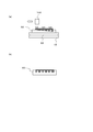
- FIG. 1 shows an example of the configuration of a printing apparatus 10 according to an embodiment of the present invention.
- FIGS. 1A and 1B are a top view and a cross-sectional view illustrating an example of a configuration of a main part of the printing apparatus 10.
- the printing apparatus 10 is an inkjet printer that performs printing on a medium (medium) 50 to be printed by an inkjet method, and includes a head unit 12, a guide rail 14, a scanning drive unit 16, a platen 18, a preheater 20, A print heater 22, an after heater 24, and a control unit 26 are provided.
- the printing apparatus 10 may have the same or similar characteristics as a known inkjet printer.
- the printing apparatus 10 may further include a known configuration necessary for a printing operation or the like.
- the head unit 12 is a portion (IJ head unit) that ejects ink droplets onto the medium 50, and includes a carriage 100, a plurality of inkjet heads 102, and a plurality of ultraviolet light sources 104.
- the carriage 100 is a holding member (head carriage) that holds other components in the head unit 12.
- the plurality of inkjet heads 102 are ejection heads that eject ink droplets by an inkjet method.
- each of the plurality of inkjet heads 102 ejects ink droplets of different colors, and deposits ink of each color on the medium 50.
- each inkjet head 102 ejects ink droplets of ink (ultraviolet absorbing ink) including at least an ultraviolet absorber (UV absorber) and a solvent.
- the ultraviolet absorber is a substance that absorbs ultraviolet rays, and generates heat by absorbing ultraviolet rays, for example. Therefore, the ink of this example is heated by irradiating with ultraviolet rays.
- each color ink used in each inkjet head 102 further includes a color material (pigment or dye) of each color.
- each of the plurality of inkjet heads 102 ejects ink droplets of each color of process colors for color printing.
- the process colors are, for example, yellow (Y), magenta (M), cyan (C), and black (K).
- the plurality of inkjet heads 102 are arranged in a predetermined main scanning direction (Y direction in the figure), and perform a main scanning operation of ejecting ink droplets while moving in the main scanning direction, thereby Ink is attached to 50.
- the plurality of inkjet heads 102 perform bidirectional (both directions) main scanning operations in one direction and the other direction in the main scanning direction.
- the ink used in this example is an evaporation-drying type ink that is fixed to the medium 50 by volatilizing and removing the solvent.
- an ink using an organic solvent as a solvent may be used as the evaporation drying type ink.
- the organic solvent may be a hydrophobic organic solvent.
- the hydrophobic organic solvent is, for example, an organic solvent that is incompatible with water.
- the solvent dissolves, for example, an ultraviolet absorber in the ink.
- the organic solvent may be a volatile organic solvent.
- it is preferable that the boiling point of the organic solvent used as a solvent is 200 degrees C or less, for example.
- an organic solvent having a boiling point lower than that of water may be 80 ° C. or less, for example.
- an ink for example, an ink obtained by adding an ultraviolet absorber to a solvent ink can be suitably used.
- the solvent ink is, for example, an ink using a hydrophobic organic solvent as a solvent.
- an ink containing an aqueous solvent may be used. More specifically, as such an ink, for example, an ink obtained by adding an ultraviolet absorber to various water-based inks can be suitably used.
- the water-based ink for example, water-based pigment ink, water-based dye ink, and the like can be suitably used.
- water-based ink resin particle-dispersed water-based inkjet ink having a structure in which resin particles are dispersed, such as latex ink or pigment-encapsulated resin-dispersed ink, can be suitably used.
- the ultraviolet absorber for example, a substance that is difficult to dissolve in an aqueous solvent may be used.
- the solvent may disperse the ultraviolet absorber in a solid state, for example, in the ink.
- the ink becomes, for example, an emulsion type (dispersion type) ink in which at least a part of the components is dispersed in the solvent.
- the ultraviolet absorber it is preferable to use a substance having an absorption peak wavelength in the ultraviolet region. Further, as the ultraviolet absorber, it is preferable to use a colorless or light-colored substance that has little influence on the color of the ink. In this case, it is preferable to use an ultraviolet absorber whose light absorptivity at the peak wavelength is twice or more the maximum value of the absorptance in the visible light region. Further, the light absorptance at the peak wavelength is preferably 5 times or more, more preferably 10 times or more, and further preferably 20 times or more with respect to the maximum value of the absorption rate in the visible light region.
- the ink includes an ultraviolet absorber in an amount of 0.01 wt% or more and 5.0 wt% (wt%) or less with respect to the total weight of the ink (whole ink composition).
- the content of the ultraviolet absorber is more preferably 1.0 to 3.0% by weight with respect to the total weight of the ink. If comprised in this way, an ultraviolet-ray can be absorbed into an ink appropriately, for example. Moreover, absorption with respect to the light of visible region can be suppressed appropriately by preventing that the quantity of a ultraviolet absorber increases too much.
- the preferred content of the UV absorber may vary from color to color. Therefore, the content of the ultraviolet absorber may be different for each color. In this case, it is preferable to adjust the content of the ultraviolet absorber in the ink of each color so that the difference in sensitivity of the ink of each color with respect to the ultraviolet ray is within about ⁇ 50%.
- the sensitivity of the ink to the ultraviolet light may be, for example, a sensitivity corresponding to the drying speed or the temperature rising speed of the ink generated by irradiating the ultraviolet light. Further, the characteristics of the ink used in this example will be described in more detail later.
- the plurality of ultraviolet light sources 104 are light sources (UV instantaneous heating irradiators) that irradiate ultraviolet rays, and heat the ink by irradiating the ink adhered on the medium 50 with ultraviolet rays. Accordingly, the ultraviolet light source 104 volatilizes and removes at least a part of the solvent contained in the ink.
- the ultraviolet light source 104 heats the ink together with a heater such as the print heater 22 to volatilize and remove the solvent in the ink.
- a heater such as the print heater 22 to volatilize and remove the solvent in the ink.
- Each of the plurality of ultraviolet light sources 104 is arranged on one side and the other side in the main scanning direction with respect to the plurality of inkjet heads 102 and moves together with the inkjet head 102 during the main scanning operation. Therefore, during the main scanning operation, one of the plurality of ultraviolet light sources 104 is located on the rear side in the movement direction with respect to the inkjet head 102, and the other is located on the front side in the movement direction.
- the ultraviolet light source 104 located behind the ink jet head 102 irradiates the ink on the medium 50 with ultraviolet light according to the moving direction of the ink jet head 102.
- the ultraviolet light source 104 irradiates the region after passing through the inkjet head 102 with ultraviolet rays, and irradiates the ink on the medium 50 with ultraviolet rays immediately after landing on the medium 50. Then, the ink viscosity is increased before bleeding occurs on the medium 50, and the occurrence of bleeding is suppressed.
- the ultraviolet light source 104 it is preferable to use a light source that can be turned on / off and that can emit ultraviolet light. Further, as such a light source, a light source (semiconductor light source) using a semiconductor that generates ultraviolet rays, such as UVLED (UVLED irradiator) and ultraviolet LD (laser diode), can be suitably used. If comprised in this way, an ultraviolet-ray can be irradiated with a high precision at a desired timing, for example. More specifically, in this example, the ultraviolet light source 104 is a light source (UV-LED irradiator) using a UV LED.
- the ultraviolet light source 104 can be considered as, for example, a UV instantaneous heating unit that rapidly heats and dries the ink within a predetermined time after the ink has landed on the medium 50.
- the ultraviolet light source 104 is disposed so as to be shifted from the positions of the plurality of inkjet heads 102, thereby irradiating the ink outside the region facing the inkjet head 102 in the medium 50 with ultraviolet rays. More specifically, in the illustrated configuration, the ultraviolet light source 104 is disposed so that the position in the main scanning direction is shifted from the inkjet head 102, thereby irradiating the ink outside the region facing the inkjet head 102 with ultraviolet rays. To do. With this configuration, for example, it is possible to appropriately prevent the inkjet head 102 from being affected by the effect of heating the ink with ultraviolet rays and the effect of the evaporated solvent.
- the time until the ultraviolet ray is irradiated after landing on the medium 50 can be adjusted appropriately.
- the width of the ultraviolet light source 104 in the main scanning direction it is possible to appropriately adjust the time for which the ultraviolet light source 104 irradiates ultraviolet rays (continuous irradiation time).
- the width of the ultraviolet light source 104 in the sub-scanning direction (X direction in the figure) orthogonal to the main scanning direction is preferably the same as the print width by the inkjet head 102 or larger than the print width.
- the print width by the inkjet head 102 is, for example, the width in the sub-scanning direction of a region where the inkjet head 102 ejects ink droplets in one main scanning operation.
- the sub-scanning direction is a direction parallel to the conveyance direction (paper feeding direction) in which the medium 50 is conveyed.
- the ultraviolet light source 104 has a width in the sub-scanning direction that is larger than the print width, and the portion deviated from the inkjet head 102 in the sub-scanning direction. Even with ultraviolet rays. As a result, the ultraviolet light source 104 irradiates ultraviolet light not only on the portion overlapping the inkjet head 102 but also on the downstream side of the inkjet head 102 in the conveyance direction of the medium 50. If comprised in this way, the timing which complete
- the ultraviolet light source 104 raises the viscosity of the ink on the medium 50 to at least a viscosity at which no bleeding occurs on the medium 50, for example, by volatilizing and removing at least a part of the solvent.
- the bleeding is, for example, an intercolor bleeding that occurs when inks of different colors are mixed.
- the viscosity at which no bleeding occurs is, for example, a viscosity at which no bleeding occurs until the ink is completely dried and fixed on the medium 50.
- the phrase “no blurring” may mean, for example, that blurring does not substantially occur within an allowable range corresponding to the required printing accuracy.
- the ultraviolet light source 104 increases the viscosity of the ink on the medium 50 to, for example, 50 mPa ⁇ s or more, preferably 100 mPa ⁇ s or more, and more preferably 200 mPa ⁇ s or more by irradiation with ultraviolet rays.
- the directivity of the ultraviolet rays emitted from the ultraviolet light source 104 is preferably set so that the ultraviolet rays do not reach the nozzle surface of the inkjet head 102. With this configuration, it is possible to appropriately prevent the inkjet head 102 from being affected by the heating performed by the ultraviolet light source 104. Further, the method of irradiating ultraviolet rays by the ultraviolet light source 104 will be described in more detail later.
- the guide rail 14 is a rail member extending in the main scanning direction, and guides the movement of the carriage 100 during the main scanning operation.
- the scanning drive unit 16 is a drive unit that causes the inkjet head 102 to perform a main scanning operation and a sub-scanning operation.
- the scanning drive unit 16 moves the carriage 100 along the guide rail 14 to move the inkjet head 102 and the like held by the carriage 100 in the main scanning direction. Then, the inkjet head 102 is caused to perform a main scanning operation by ejecting ink droplets to the moving inkjet head 102 based on print data indicating an image to be printed (color image or the like).
- causing the inkjet head 102 to perform the sub-scanning operation means, for example, moving the inkjet head 102 in the sub-scanning direction relative to the medium 50. More specifically, in this example, the scan driving unit 16 causes the inkjet head 102 to perform a sub-scanning operation by transporting the medium 50 in the transport direction parallel to the sub-scanning direction. Further, the scan driving unit 16 changes the area of the medium 50 that faces the inkjet head 102 in the next main scanning operation by conveying the medium 50 between the main scanning operations. Accordingly, the scan driving unit 16 causes the ink jet head 102 to eject ink droplets to each position of the medium 50.
- the scan driving unit 16 further moves the ultraviolet light source 104 together with the inkjet head 102 during the main scanning operation, so that the ultraviolet light source 104 is irradiated with ultraviolet rays in accordance with the ink droplet ejection position by the inkjet head 102.
- the platen 18 is a table-like member disposed at a position facing the head unit 12, and supports the medium 50 by facing the head unit 12 by placing the medium 50 on the upper surface.
- the platen 18 accommodates therein a pre-heater 20 that is a heater (heating heater) for heating the medium 50, a print heater 22, and an after-heater 24.
- the pre-heater 20, the print heater 22, and the after-heater 24 are heating means for heating the medium 50.
- the solvent in the ink is volatilized and removed. Dry.
- the heating means in addition to the ultraviolet light source 104, the solvent in the ink can be volatilized and removed more appropriately, and the drying of the ink can be further promoted. This also makes it possible to more appropriately fix the ink on the medium 50.
- the preheater 20 is a heater that preheats the medium 50, and is disposed upstream of the inkjet head 102 in the conveyance direction of the medium 50, whereby ink droplets land on the medium 50. Heat the previous area.
- the print heater 22 is a heater that heats the medium 50 at a position facing the inkjet head 102.
- the ultraviolet light source 104 volatilizes and removes at least part of the solvent contained in the ink together with the print heater 22 by irradiating the ink on the medium 50 heated by the print heater 22 with ultraviolet light. If comprised in this way, the solvent in ink can be volatilized and removed more appropriately from the ink immediately after landing on the medium 50, for example. In addition, this makes it possible to increase the viscosity of the ink more appropriately before bleeding occurs on the medium 50.
- the after heater 24 is a heater disposed on the downstream side of the inkjet head 102 in the transport direction, and further heats the medium 50 after passing through the positions of the print heater 22 and the ultraviolet light source 104, whereby the ultraviolet light source 104 and The solvent that could not be removed by the print heater 22 is removed. Thereby, the after-heater 24 dries the ink on the medium 50 more reliably and fixes it to the medium 50, for example.
- a heat transfer type heater for heating the medium 50 by heat conduction from the inside of the platen 18 is illustrated as the after heater 24.
- a heater other than the heat transfer type may be used as the after heater 24.
- the after heater 24 for example, a dryer such as a warm air heater or an infrared heater may be used.
- these configurations may be further used.
- the control unit 26 is, for example, a CPU of the printing apparatus 10 and controls each unit of the printing apparatus 10. According to this example, for example, printing on the medium 50 can be performed appropriately.
- the ink can be efficiently heated by irradiation with ultraviolet rays immediately after the landing of the ink droplet. Accordingly, even when the print heater 22 or the like that heats the medium 50 at a position facing the ink jet head 102 is used as in this example, the heating temperature by the print heater 22 or the like can be appropriately suppressed. Therefore, according to this example, for example, the solvent in the ink can be appropriately volatilized and removed while suppressing the influence on the nozzle surface of the inkjet head 102 and the like. This also makes it possible to appropriately increase the viscosity of the ink before ink bleeding occurs, for example.
- the ink can be appropriately fixed on the medium 50 by drying the ink by irradiation of ultraviolet rays or the like. Furthermore, in this example, by heating the medium 50 with the preheater 20, the print heater 22, and the afterheater 24, the ink can be dried more appropriately than when heating only with the ultraviolet light source 104, for example. it can. Thus, according to this example, for example, in the case of using evaporation-drying ink, it is possible to appropriately suppress ink bleeding. Thereby, for example, high quality printing can be appropriately performed.
- the configuration of the printing apparatus 10 in this example can be considered as a configuration in which a plurality of heating units are used as a unit (fixing unit) for drying the evaporation drying type ink, for example.
- the print heater 22 or the like is used as a first heating unit that heats the medium 50 from the back side at a position (printing position) where ink droplets are ejected by the inkjet head 102.
- the ultraviolet light source 104 is used as the second heating means in combination with the first heating means.
- the first heating unit is preferably a unit that performs heating at a temperature of 70 ° C. or lower, for example.
- the heating temperature by the first heating means is more preferably 60 ° C. or lower.
- the second heating unit irradiates each position of the medium 50 with ultraviolet rays after landing of the ink droplets ejected by the inkjet head in time series.
- an ultraviolet light source 104 capable of on / off control of ultraviolet irradiation.
- the ink is heated only by the ultraviolet light source 104 without using a heater such as the print heater 22.
- another heating unit may be used.
- an infrared light source or the like may be further disposed at a position facing the after heater 24 on the downstream side of the ultraviolet light source 104 in the transport direction.
- the ink on the medium 50 can be dried more reliably and appropriately, for example by performing heating with an infrared light source etc. with the after-heater 24, for example. Moreover, when using a heating means such as an infrared light source, it may be omitted as the after heater 24.
- the ink is heated using ultraviolet rays, which are light that has little influence on the color of the ink.
- ultraviolet rays which are light that has little influence on the color of the ink.
- a configuration for heating the ink using light that has little influence on the color of the ink for example, a configuration using an infrared light source in place of the ultraviolet light source 104 and using infrared light may be considered. Also in this case, for example, if an infrared absorbent that is transparent to light in the visible light region is used, it is possible to suppress the occurrence of bleeding without affecting the printed color.
- infrared absorbers usually exhibit absorption that is not negligible for light in the visible light region. Therefore, when trying to suppress the influence on the printed color, the range of selection of the substance used as the infrared absorber is narrowed. As a result, it may be difficult to appropriately use ink having desired characteristics.
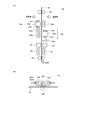
- FIG. 2 is a diagram (a model of a drying process) showing an example of a printing operation in a conventional printing apparatus in a simplified manner (modeling of a drying process).
- ink that does not include an ultraviolet absorber (including an ultraviolet absorber)
- An example of a printing operation in the case of drying ink using only a heater (print heater 22 or the like) provided in the platen 18 will be described.
- a printing device having the same or similar configuration as the configuration in which the ultraviolet light source 104 is omitted from the printing device 10 shown in FIG. 1 is used.
- FIG. 2A shows an example of an operation for ejecting ink droplets onto the medium 50.
- FIG. 2B is a cross-sectional view illustrating an example of the medium 50 after the printing operation is completed.
- the ink used in the configuration shown in FIG. 2 may be the same as or similar to the ink used in the printing apparatus 10 shown in FIG. 1 except that it does not contain an ultraviolet absorber, for example. Further, this ink may be, for example, a known evaporative drying ink. More specifically, FIG. 2 shows a case where a known aqueous ink is used.
- the medium 50 a medium 50 (permeable medium) having a property of absorbing ink before the solvent is volatilized and removed is used. More specifically, the medium 50 is paper, cloth (cloth), or the like.
- the entire medium 50 is heated with a heater such as the print heater 22. This also volatilizes and removes the solvent in the ink and suppresses ink bleeding on the medium 50.
- a heater such as the print heater 22.
- ink droplets are ejected onto the medium 50 by the inkjet head 102 while being heated by the print heater 22.
- the entire area where the ink droplets land on the medium 50 is set to, for example, 70 ° C. or less (for example, 70 ° C. or less) by the print heater 22 disposed at a position facing the inkjet head 102 in the platen 18. It is heated to a temperature of about 50 to 70 ° C., preferably 60 ° C. or less (eg, 50 to 60 ° C.).
- the ink layer formed on the surface of the medium 50 is heated to increase the viscosity of the ink, thereby suppressing the occurrence of ink bleeding.
- the ink jet head 102 located at the position facing the print heater 22 with the medium 50 interposed therebetween is also affected by heat radiation. Therefore, if the heating temperature by the print heater 22 is set to a higher temperature than the above temperature, the influence of thermal radiation on the ink jet head 102 is increased. As a result, for example, ink in the vicinity of the nozzles in the inkjet head 102 is dried, and nozzle clogging is likely to occur. Therefore, it is difficult to raise the heating temperature from the above range.
- the evaporated solvent is agglomerated and adhered to the inkjet head 102 at a relatively low temperature, thereby preventing stable ink ejection. Therefore, also in this respect, it is difficult to increase the heating temperature by the print heater 22.
- the heating temperature of the medium 50 is preferably set to the above temperature (medium temperature). That is, by heating the medium 50 at such an intermediate temperature by the print heater 22, the solvent in the ink can be volatilized and removed while suppressing the influence of heat radiation.
- the ink drying speed becomes lower than the printing speed, and problems such as the occurrence of bleeding occur.
- the number of printing passes is reduced. More specifically, when printing is performed with the conventional configuration as described above, the number of printing passes is normally set to about 8 to 32 passes. In this case, if the number of passes is reduced, the amount of ink that lands on a unit area per unit time increases, so the drying speed may not be in time.
- the ink penetrates deeply into the medium 50 due to the passage of time after landing due to capillary action. As a result, the amount of ink remaining on the surface of the medium 50 is reduced. As a result, the printing density is lowered and the printed color becomes lighter. In addition, problems such as a blurred print result (printed matter) are likely to occur. In other words, when printing is performed with a conventional printing apparatus, if the printing speed is increased, the color of the printing result when the printed surface is observed becomes lighter and bleeding problems tend to occur.
- the temperature of the print heater 22 may be raised in order to suppress problems such as ink bleeding. If comprised in this way, since the evaporation rate of a solvent becomes quick, problems, such as a bleed, can be improved.
- problems such as a bleed
- the heating temperature by the print heater 22 has an upper limit temperature for maintaining stable ejection of ink droplets. As a result, if the printing speed is increased, the printing apparatus configured to increase the amount of ink landed per unit time with respect to the unit area has a limit on speeding up.
- the heating temperature by the print heater 22 is usually selected in the range of about 50 to 60 ° C. or about 40 to 60 ° C. as described above.
- the heating temperature of the print heater 22 is lowered (for example, about 40 ° C.).
- the ink spreads in the direction of the surface of the medium 50 and bleeding is particularly likely to occur under high speed printing conditions in which the amount of ink that lands on a unit area per unit time increases. Become. More specifically, for example, when the number of printing passes is reduced to about 8 or less (1 to 8 passes) in order to increase the printing speed, the amount of ink landed per unit time increases per unit area. In the temperature range in which ejection failure can be avoided, it becomes more difficult to prevent bleeding using only the print heater 22. Therefore, when printing is performed with a conventional printing apparatus, it is difficult to perform printing at high speed while suppressing problems such as bleeding.
- FIG. 3 is a diagram (model of a drying process) showing a simplified example of a printing operation by the printing apparatus 10 of the present example.
- FIG. 3A shows an example of an operation for ejecting ink droplets onto the medium 50.
- the ultraviolet light source 104 and the print heater 22 are used to rapidly volatilize and remove the solvent in the ink. This also dries the ink immediately after landing on the medium 50 and increases the viscosity of the ink to a viscosity at which no bleeding occurs.
- the temperature of heating by the print heater 22 can be set lower than when the ink is dried only by the print heater 22.
- the heating temperature by the print heater 22 is, for example, the heating temperature of the print heater 22 with respect to a region facing the inkjet head 102.
- the ultraviolet light source 104 irradiates ink outside the region facing the inkjet head 102 in the medium 50 with ultraviolet rays.
- the ink solvent evaporates relatively slowly only by heating of the print heater 22 at a position facing the inkjet head 102 in the medium 50. Therefore, it is possible to appropriately prevent the problem that the evaporated solvent agglomerates and adheres to the inkjet head 102. In addition, this makes it possible to improve the ejection stability more appropriately.
- the ink ejected by the inkjet head 102 and landed on the medium 50 is, for example, printed by the print heater 22 in a region facing the inkjet head 102 before being irradiated with ultraviolet rays by the ultraviolet light source 104.
- Preheating is performed at a relatively low temperature of 70 ° C. or less, preferably 60 ° C. or less (eg, about 20 to 60 ° C.).
- the heating temperature by the print heater 22 is more preferably about 20 to 50 ° C., further preferably about 20 to 45 ° C.
- the heating temperature by the print heater 22 may be, for example, about the heating temperature of the print heater in a known low-speed printer that does not perform high-speed printing.
- the ultraviolet light source 104 irradiates the vicinity of the region facing the inkjet head 102 with the ultraviolet light source 104, thereby directly heating the ink in the region to rapidly evaporate the ink solvent, Increase the viscosity of the ink. If comprised in this way, the viscosity of an ink can be raised before a blurring generate
- the inkjet head 102 by irradiating ultraviolet rays while avoiding the region facing the inkjet head 102, it is possible to appropriately prevent the inkjet head 102 from being affected by radiant heat and solvent evaporation caused by the irradiation of the ultraviolet light source 104. Therefore, according to this example, it is possible to increase the viscosity of the ink immediately after landing, for example, without disturbing the stable ejection of the ink.
- the ultraviolet light source 104 moves in the main scanning direction together with the inkjet head 102 during the main scanning operation. Then, ultraviolet rays are irradiated toward the ink on the medium 50 by the ultraviolet light source 104 located on the rear side in the moving direction of the inkjet head 102.
- each position of the medium 50 can be irradiated with ultraviolet rays by the ultraviolet light source 104 immediately after passing through the inkjet head 102, and only the landed ink portion can selectively absorb ultraviolet rays.
- this makes it possible to selectively rapidly heat only the ink layer on the medium 50 rather than heating the entire medium 50 to a high temperature.
- by removing the solvent in the ink by volatilization by this heating and increasing the viscosity of the ink it is possible to appropriately prevent the ink from bleeding.
- the ultraviolet light source 104 irradiates the area after passing through the inkjet head 102 with ultraviolet light. Therefore, it is possible to appropriately prevent the inkjet head 102 from being affected by the heat radiation of the heating by the ultraviolet light source 104, and the solvent evaporated by the irradiation of ultraviolet rays to be aggregated on the nozzle surface of the inkjet head 102. Therefore, in this example, the discharge can be stabilized also in this respect.
- evaporative drying ink is used in this example.
- the solvent in the ink is volatilized and removed by the print heater 22 and the ultraviolet light source 104, so that the ink can be appropriately fixed to the medium 50.
- the ink can be dried more reliably by heating with the after heater 24 on the downstream side of the ultraviolet light source 104 in the conveyance direction of the medium 50. . Therefore, according to this example, for example, the ink can be more reliably fixed to the medium 50.
- FIG. 3B is a cross-sectional view showing an example of the medium 50 after the printing operation is completed.
- the viscosity of the ink is increased before a large amount of ink is absorbed by the medium 50, and the ink is rapidly dried near the surface of the medium 50. it can.
- the amount of ink penetrating into the medium 50 is reduced (shallow), and a large amount of ink remains in the vicinity of the surface of the medium 50, so that the thickness of the ink on the surface can be sufficiently increased.
- this makes it possible to appropriately prevent the printed color from becoming thin and to make the ink color sufficiently dark and perform clear printing.
- the ultraviolet light source 104 or the like for example, the remaining rate and remaining time of the solvent remaining in the medium 50 that is a permeable medium can be reduced. This also makes it possible to appropriately prevent the occurrence of cockling, curling, etc. that occur when a medium 50 such as paper is used.
- the ink can be dried more reliably in a short time as described above. Therefore, for example, the medium 50 after printing can be quickly transferred to a subsequent process. Further, for example, when using the printing apparatus 10 configured to wind up the medium 50 after printing, a show-through problem or the like that occurs after winding can be appropriately prevented even with a high-speed machine that has increased printing speed.
- the inventor of the present application has confirmed through experiments and the like that about 80% of the solvent in the ink can be removed by irradiating the ultraviolet light from the ultraviolet light source 104. Therefore, in the configuration of this example, it is possible to remove most of the solvent in the ink and fix the ink to the medium 50 only by irradiating ultraviolet rays, for example.
- the ink slightly penetrates into the medium 50 as shown in FIG. 3B, for example.
- the amount of ink permeation can be greatly reduced as compared with the case where printing is performed with a conventional configuration that does not use the ultraviolet light source 104.
- the type of the medium 50 used in the printing apparatus 10 of this example is not particularly limited. For this reason, in the printing apparatus 10, it may be considered to use a medium 50 (non-permeable medium, non-absorbable medium) having a property that ink does not penetrate into the inside at all.
- FIG. 3C is a cross-sectional view showing an example of the medium 50 after completion of the printing operation in the case where the non-permeable medium is used.
- the medium 50 does not absorb ink before the viscosity of the ink is increased by heating with the print heater 22 or irradiation with ultraviolet rays. Therefore, in this case, the surface of the medium 50 remains thick in the state after printing. Also in this case, it is possible to appropriately prevent the occurrence of bleeding by increasing the viscosity of the ink by the ultraviolet light source 104. This also makes it possible to appropriately perform printing on the medium 50 while suppressing the occurrence of bleeding and the like.
- the ink since the ink does not penetrate into the medium 50, the amount of ink attached to the medium 50 can be reduced as compared with the case where the permeable medium 50 is used.
- the permeable medium 50 With such a configuration, for example, it is possible to appropriately suppress ink bleeding or the like and appropriately perform dark color printing with a smaller amount of ink.
- the viscosity of the ink can be appropriately increased after landing on the medium 50 and before bleeding occurs.
- this makes it possible to increase the printing speed by increasing the amount of ink landed per unit time per unit area, for example.
- a conventional printing apparatus printing is usually performed by a multipass method of at least 8 passes.
- the ink discharge amount in one main scanning operation is 12.5% at maximum per color and 50% in total for four colors.
- it is necessary to use a larger number of passes for example, 16 passes, 32 passes, etc..
- the number of printing passes is increased, the printing speed is greatly reduced. Therefore, in the conventional configuration, it can be said that it is difficult to increase the printing speed due to the problem of bleeding that occurs in the process of drying the ink solvent.
- the amount of ink landed in a unit time per unit area is increased by reducing the number of passes, for example, by volatilizing and removing the solvent in the ink by ultraviolet irradiation.
- the occurrence of bleeding can be appropriately suppressed. Therefore, according to the present example, for example, when printing is performed by the multi-pass method, it is possible to appropriately reduce the number of passes and perform high-speed printing (high-speed printing) more appropriately. In addition, this makes it possible to print without causing bleeding even when the speed is increased beyond the limit of the conventional method.
- the ultraviolet light source 104 can be used to appropriately prevent bleeding.
- high quality printing can be performed more appropriately than in the past. That is, according to this example, for example, a high-speed printing apparatus (high-speed printer) in which the number of printing passes is 8 or less can be appropriately realized.
- the number of passes can be less than 8 passes (for example, 4 passes or less). Further, it can be said that the effect of preventing bleeding by using the ultraviolet light source 104 is particularly remarkable when the number of printing passes is about 1 to 4 passes. Further, according to this example, for example, it is possible to perform printing in one pass without performing printing in a multi-pass method.
- a remarkable effect can be obtained even when the number of passes is 4 or more. Furthermore, in this case, even when printing is performed with a number of passes larger than 8 passes, a remarkable effect can be obtained as an effect of preventing bleeding by using the ultraviolet light source 104. In this case, for example, it is conceivable to perform printing with the number of passes of about 32 passes or less (for example, 16 to 32 passes).
- the effect of preventing bleeding by using the ultraviolet light source 104 is a useful effect other than for a high-speed printer that performs high-speed printing, for example.
- the printing apparatus 10 of this example can be suitably used for printing in various fields, not limited to a specific field (such as the SG field) for high-speed printing.
- the viscosity of adjacent ink dots can be sufficiently increased before mixing. Therefore, for example, it is possible to prevent streaks and the like from being formed by connecting ink dots.
- the ink used in this example includes an ultraviolet absorber, a solvent, a coloring material, and the like. More specifically, in this configuration, it is preferable to use a substance having an absorption characteristic in accordance with the wavelength of ultraviolet rays generated by the ultraviolet light source 104 as the ultraviolet absorber. Moreover, it can be said that it is preferable to use the ultraviolet absorber which shows strong light absorption with respect to the light emission wavelength range of ultraviolet light sources 104, such as UVLED, about this relationship.
- the ultraviolet light source 104 that irradiates ultraviolet rays within a wavelength range that is absorbed by the ultraviolet absorber to be used.
- the emission wavelength of the ultraviolet light source 104 substantially matches the ultraviolet absorption band of the ultraviolet absorbent contained in the ink.
- the ultraviolet light source 104 emits ultraviolet light having a wavelength of 410 nm or less, for example.
- a light source using a UV LED or the like having an emission center wavelength in the near ultraviolet region for example, a range of 250 to 410 nm, preferably a range of 250 to 400 nm
- an ultraviolet absorbent having strong absorption only in a predetermined wavelength range of ultraviolet rays having a wavelength of 410 nm or less is added to the ink and combined with the ultraviolet light source 104.
- an ultraviolet absorber that selectively absorbs ultraviolet rays in a wavelength range generated by the UV LED used as the ultraviolet light source 104 and does not have a remarkable absorption characteristic in the visible light region.
- the selective absorption of ultraviolet rays in the wavelength range generated by the UVLED means, for example, that a large absorption characteristic is exhibited in the vicinity of the emission wavelength of the UVLED in the ultraviolet light source 104.
- the fact that there is no significant absorption characteristic in the visible light region is, for example, that it is substantially transparent to visible light. If comprised in this way, the ink on the medium 50 can be directly and selectively heated by ultraviolet irradiation, for example, and the solvent in ink can be volatilized and removed appropriately.
- the UV absorption rate is 10% or more under the condition that the ink thickness is 20 ⁇ m and the UV LED irradiates the UV in the wavelength region of 250 to 410 nm. It is preferable that Further, it is more preferable that the absorption rate of ultraviolet rays under these conditions is 20% or more.
- the absorption characteristics with respect to light in the visible light region for example, ⁇ E in the L * a * b * color system before and after the addition of the ultraviolet absorber for the color tone of a basic color ink (color ink) such as YMCRGB.
- the color difference is preferably 20 or less.
- the ⁇ E color difference generated by the addition of the ultraviolet absorber is more preferably 10 or less.
- the ultraviolet absorber a known ultraviolet absorber having the above characteristics can be suitably used.
- the ink of this example may contain a benzotriazole ultraviolet absorber, a liquid ultraviolet absorber, a triazine ultraviolet absorber, a benzophenone ultraviolet absorber, a benzoate ultraviolet absorber, or the like as an ultraviolet absorber.
- benzotriazole ultraviolet absorber for example, an ultraviolet absorber selected from TINUVIN P, TINUVIN 234, TINUVIN 326, TINUVIN 328, and TINUVIN 329 may be used.
- liquid ultraviolet absorber for example, an ultraviolet absorber selected from TINUVIN 213 and TINUVIN 571 may be used.
- TINUVIN 1577 ED can be used as the triazine-based ultraviolet absorber.
- benzophenone ultraviolet absorber for example, CHIMASSORB 81 can be used.
- benzoate ultraviolet absorber for example, TINUVIN 120 can be used.
- an ultraviolet absorber for example, an ultraviolet absorber selected from TINUVIN 400, TINUVIN 405, and TINUVIN 479 may be used.
- TINUVIN and CHIMASSORB are registered trademarks.
- the ultraviolet absorber shown above using these registered trademarks is an ultraviolet absorber manufactured by BASF.
- the various ultraviolet absorbers described above may be used alone or in combination of two or more.
- the transmittance of the ultraviolet absorber with respect to light in the visible light region is preferably 60% or more. If comprised in this way, the ultraviolet absorber will be substantially transparent with respect to visible light, and the change of the color of the ink by including an ultraviolet absorber can be suppressed appropriately.
- the transmittance of the ultraviolet absorber with respect to light in the visible light region is preferably 70% or more, more preferably 80% or more, and still more preferably 90% or more. If comprised in this way, a highly transparent ultraviolet absorber with little light absorption with respect to visible light can be used appropriately, for example. This also makes it possible to appropriately prevent, for example, ink turbidity and a decrease in brightness with respect to the visible light region.
- the ultraviolet absorber is added so as to be dissolved or dispersed in a solvent, for example.
- the ultraviolet absorber may be dissolved or dispersed in other components in the ink.
- the other component in the ink is, for example, a component resin included in the ink.
- the component resin is a resin that the ink contains as a component.
- dispersing the ultraviolet absorber in the component resin or the like may mean, for example, dispersing the ultraviolet absorber in a solid state in the binder resin or the like.
- the component resin may be, for example, a binder resin.
- the ultraviolet absorber can be dissolved or dispersed in the solvent by dissolving or dispersing the binder resin or the like in the solvent.
- an ink obtained by adding an ultraviolet absorber to a latex ink it may be possible to dissolve or disperse the ultraviolet absorber in the latex resin.
- an organic ultraviolet absorber it is conceivable to use various organic ultraviolet absorbers as described above.
- an ultraviolet absorber you may use not only the above but another substance.
- an inorganic substance may be used as the ultraviolet absorber.
- transparent fine particles such as zinc oxide and titanium oxide are dispersed and added in a solvent.
- these ultraviolet absorbers may be dispersed and added in the component resin, and the component resin may be dispersed in the ink solvent.
- the ultraviolet absorber when water or some organic solvent is used as the main component of the solvent, the ultraviolet absorber may not be dissolved in the solvent.
- the main component of the solvent is a component having the highest content among the liquids constituting the solvent.
- the solvent is the main component of the ink.
- a main component is a component contained most by weight ratio, for example.
- the solvent is preferably a component that occupies 50% by weight or more of the total weight of the ink, for example. If comprised in this way, the viscosity of the ink before discharge from the inkjet head 102 can be appropriately adjusted to the low viscosity suitable for discharge by an inkjet system, for example.
- the solvent for the ink for example, it is conceivable to use a solvent (organic solvent) having a boiling point of 200 ° C. or less as the main component, water, or the like.
- the ink By using such ink, for example, after landing on the medium 50, it is possible to appropriately prevent the ink from bleeding by evaporating the solvent, which is the main component, by irradiation with ultraviolet rays or the like. Further, by evaporating the solvent, the evaporation-drying type ink can be appropriately fixed (dry-fixed) to the medium 50.
- the ink can be dried in a short time by irradiating with ultraviolet rays, a combination of the ink and the medium 50 that has been difficult to print properly with the conventional configuration is realized. Etc. are also possible. More specifically, various evaporative drying inks can be used even when, for example, a paper on which an image receiving layer is not formed, a cloth that is not pretreated, or the like is used as the medium 50. Thereby, for example, the running cost of printing can be significantly reduced.
- the ink includes color materials of each color.
- the color of the ink is not particularly limited.
- the ink having the above-described configuration is used for each color of YMCK.
- it is conceivable to use inks of colors such as white, clear, red (R), green (G), blue (B), and orange (Org).
- an ultraviolet curable ink for example, an ultraviolet curable ink (UV ink) containing a monomer or the like has been widely used.
- an ultraviolet absorber used with the ink of this example you may use the same or similar ultraviolet absorber as the component of an ultraviolet curable ink, for example.
- the phenomenon that occurs when the ultraviolet absorber absorbs ultraviolet rays is completely different between the ink of this example and the conventional ultraviolet curable ink. More specifically, in the case of an ultraviolet curable ink, a polymerization reaction of a monomer or the like is caused by irradiation with ultraviolet light, the ink is cured by a polymerization reaction, and the ink is fixed (cured and fixed) to a medium. Therefore, in this case, the phenomenon caused by the irradiation with ultraviolet rays is a chemical phenomenon.
- the ink is fixed (dry-fixed) to the medium by evaporating the solvent in the ink, not by the polymerization reaction.
- the ultraviolet absorber functions as a heat source that generates heat in response to the ultraviolet rays. Therefore, in this case, the phenomenon caused by the ultraviolet rays is a physical phenomenon and is completely different from the case of the ultraviolet curable ink.
- an ultraviolet lamp or the like is known in addition to a semiconductor light source such as UVLED or ultraviolet LD.
- a semiconductor light source such as UVLED or ultraviolet LD.
- an ultraviolet lamp or the like instead of the semiconductor light source as the ultraviolet light source 104.
- an ultraviolet lamp unlike a semiconductor light source, an ultraviolet lamp usually cannot be switched on and off at high speed. Moreover, an ultraviolet lamp normally heats a wide range simultaneously compared with UVLED etc. Therefore, when an ultraviolet lamp is used as the ultraviolet light source 104, the medium 50 having low heat resistance cannot be used, for example, under conditions of high temperature drying that can volatilize and remove the solvent in a short time. In this case, the medium 50 and the ink may be burned or discolored.
- ultraviolet lamps or the like usually generate light that contains a large amount of visible light or the like that has low conversion efficiency to ultraviolet rays and is less effective for heating. In this case, it becomes difficult to selectively heat only the ink, and the medium 50 and surrounding members are also heated simultaneously with the ink. Further, much of the energy input to the ultraviolet lamp becomes heat, and is radiated through the medium 50, resulting in loss. In addition, as a result, there is a disadvantage that the energy utilization efficiency used for drying the ink is lowered.
- a semiconductor light source such as UVLED as the ultraviolet light source 104 as described above. If comprised in this way, the ultraviolet-ray of a specific wavelength range can be irradiated efficiently. Further, by using an ink containing an ultraviolet absorber that matches the wavelength range of the ultraviolet rays to be used, the ink can be appropriately heated while suppressing the influence on the medium 50 and the like. Moreover, this can prevent the occurrence of bleeding appropriately.
- the irradiation intensity of ultraviolet rays by the UVLED has been remarkably improved as compared with the previous time due to technological progress in recent years (for example, for the last 5 years or so).
- a semiconductor light source to irradiate ultraviolet rays, it is possible to switch on and off at a high speed, unlike when using an ultraviolet lamp or the like. Therefore, if comprised in this way, on-off of the ultraviolet light source 104 can also be switched appropriately as needed, for example.
- the method of heating the ink by the ultraviolet light source 104 it is preferable to heat the ink on the medium 50 at once in a short time.
- the temperature of the ink solvent is raised to a temperature equal to or higher than the boiling point at the position where the ultraviolet ray is irradiated by the ultraviolet ray irradiation for such continuous irradiation time.
- the boiling point of the solvent of the ink is, for example, the boiling point of the solvent that is the main component of the ink.
- the solvent component in the ink can be evaporated at once and bleeding can be appropriately prevented.
- bleeding in the surface direction parallel to the surface of the medium 50 not only the bleeding in the thickness direction of the medium 50 can be appropriately prevented.
- a large amount of ink can be left on the surface of the medium 50. Therefore, for example, even when a permeable medium is used as the medium 50, a dark color image, a monochrome image, or the like can be printed more appropriately. Thereby, clear printing can be performed more appropriately.
- the heat that escapes through the medium 50 when the medium 50 is heated will be described in more detail.
- the ink is heated by irradiation with ultraviolet rays, it is necessary to consider the amount of heat dissipated through the medium 50, the loss of heat energy, and the like. More specifically, for example, when the irradiation intensity of the ultraviolet light source 104 is low, it is difficult to sufficiently raise the temperature by the heat escaping through the medium 50. As a result, it becomes difficult to appropriately prevent ink bleeding.
- the temperature in order to reduce the influence of the amount of heat radiated through the medium 50 (temperature decrease, etc.) and the influence of loss of thermal energy, for example, it is sufficient in a range in which the medium 50 and ink are not burned due to overheating. It is preferable to raise the temperature in a short time to a temperature close to the boiling point of the main component of the solvent. In this case, as described above, it is preferable that the continuous irradiation time of ultraviolet rays is sufficiently shorter than the thermal time constant ⁇ of heat radiation of the medium 50. With this configuration, for example, the temperature can be appropriately increased in a short time to a temperature near the boiling point of the main component of the ink solvent.
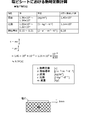
- the transfer rate of heat escaping through the medium 50 is determined by a thermal time constant ⁇ expressed by the following equation.
- the thermal time constant ⁇ of the medium 50 varies depending on the material and thickness of the medium 50 to be used.
- FIG. 4 is a diagram for explaining the thermal time constant ⁇ of the medium 50 in more detail, and shows an example of the calculation result of the thermal time constant when the vinyl chloride medium 50 (vinyl chloride sheet) is used. More specifically, the thermal time constant ⁇ of the medium 50 can be calculated as shown in FIG. In the illustrated case, the thermal time constant is 9.18 seconds. That is, in a normal vinyl chloride film having a thickness of about 1 mm, the thermal time constant can be said to be about 10 seconds.
- the thermal time constant is considered to be approximately the same in many cases.
- the thermal time constant is several seconds or more (for example, about 5 seconds or more). Therefore, the continuous irradiation time by the ultraviolet light source 104 is preferably set to 3 seconds or less, for example.
- the continuous irradiation time by the ultraviolet light source 104 is more preferably 0.2 seconds or less.
- the inventors of the present application have confirmed through experiments and the like that only the ink layer on the medium 50 can be efficiently heated to a high temperature when the continuous irradiation time of ultraviolet rays is set in this way. Furthermore, it was confirmed that the thermal efficiency of heating was further increased by setting the continuous irradiation time to 0.1 seconds or less.
- the ultraviolet light source 104 is moved at the same moving speed as the inkjet head 102 during the main scanning operation.
- the heating time (continuous irradiation time) with ultraviolet rays can be adjusted, for example, by adjusting the width of the ultraviolet light source 104 in the main scanning direction.
- the moving speed of the inkjet head 102 during the main scanning operation is usually about 500 to 1000 mm / s.
- the width of the ultraviolet light source 104 in the main scanning direction is about 50 mm
- the heating temperature of the ink can be adjusted by adjusting the irradiation intensity of the ultraviolet light source 104. In addition, this makes it possible to volatilize and remove the solvent of the ink appropriately and with a set continuous irradiation time. Further, in this case, by performing heating while moving the ultraviolet light source 104, the medium 50 and ink can be prevented from being burned due to overheating, and heating of each position of the medium 50 for a short time with strong ultraviolet light is realized. It can be said that.
- the structure which can irradiate a strong ultraviolet-ray in a short time is implement
- this makes it possible to appropriately heat the ink while preventing the medium 50 from being burnt.
- the irradiation intensity (necessary energy of the ultraviolet light source 104) necessary for heating the ink (steady heating of the ink layer), the amount of heat escaping from the medium, and the like can be calculated as follows.
- the irradiation intensity (energy) necessary for heating the ink the thickness of the ink on the medium 50 is D (cm)
- the absorption rate of ultraviolet rays in the ink is ⁇
- the specific heat of the ink is 4.2 (Joule / gr).
- Formula (2) become.
- the amount of heat escaping from the medium (heat dissipation loss energy amount) is approximately 1 cm, assuming that the thermal conductivity is 0.25 (W / mK), the temperature difference between the front and back of the medium 50 is 10 ° C., the thickness is 1 mm.
- the energy E1 can also be considered as a heat loss during steady heating for slowly heating the medium 50.
- more energy is lost through the medium 50 than the energy for heating the ink layer when heating is performed under normal equilibrium conditions where heating is performed slowly.
- the thermal time constant heat capacity ⁇ thermal resistance
- efficient heating can be performed by supplying small energy close to Equation (1) under short-time heating conditions with little heat loss.
- the evaporation rate of the solvent of the ink can be accelerated by increasing the temperature of the solvent instantaneously to the boiling point of the solvent included in the ink or higher.
- there is an upper limit on the heating rate and it is necessary to keep the temperature within a range in which the ink to be used and the medium 50 in contact with the ink do not burn.
- the inventors of the present application conducted specific experiments by combining inks containing various known ultraviolet absorbers with known UV LEDs. Then, it was confirmed that ink bleeding can be efficiently and appropriately suppressed by irradiating with ultraviolet rays under conditions where the irradiation intensity of ultraviolet rays is various and the continuous irradiation time is 2 to 0.3 seconds or less. In addition, it was confirmed that the conditions for avoiding scorching due to overheating of the medium 50 and ink can be appropriately realized. Further, it was confirmed that the irradiation intensity of ultraviolet rays from the ultraviolet light source 104 is preferably at least 0.3 W / cm 2 or more.
- the irradiation intensity of ultraviolet rays is preferably 0.5 w / cm 2 or more, more preferably 1 W / cm 2 or more, and further preferably 5 W / cm 2 or more. Further, further experiments and examinations have confirmed that these points are not limited to the case of using a specific ultraviolet absorber or UVLED.
- the ink temperature change was also confirmed in the case where the ultraviolet ray was irradiated to the ink containing the ultraviolet absorber by the UVLED.
- this experiment confirmed that the ink was properly fixed on the medium 50 by increasing the temperature of the ink to about 100 to 170 ° C. Further, it was confirmed that scorching occurred when the temperature of the ink became high (for example, when the temperature exceeded about 400 ° C.). Further, it was confirmed that, when the ultraviolet irradiation time was set longer than the thermal time constant of the medium 50, the burning easily occurred when the ultraviolet irradiation intensity was set to about 1 W / cm 2 or more.
- the predetermined time is determined according to, for example, the medium 50 to be used and the bleeding speed governed by the ink viscosity and surface tension. More specifically, for example, it is usually preferable to irradiate ultraviolet rays within about 0.05 to 2 seconds after ink droplets have landed. Further, the time until irradiation with ultraviolet rays can be set, for example, by adjusting the distance between the inkjet head 102 and the ultraviolet light source 104 according to the moving speed of the inkjet head 102 during the main scanning operation. .
- permeable media such as paper and cloth (for example, sewing products such as fabrics and T-shirts) that are easy to spread is used as the medium 50 used in the printing apparatus 10 has been described. According to this example, for example, when printing is performed at high speed on a permeable medium that is likely to cause bleeding, a remarkable effect of preventing bleeding can be obtained.
- the permeable medium not only the permeable medium but also various media 50 can be used.
- a non-permeable medium 50 for example, it is also conceivable to use a non-permeable medium 50.
- the effect of preventing bleeding can be appropriately obtained by the configuration in which the ink is rapidly dried.
- various porous media, non-permeable plastic films (such as PET), vinyl chloride sheets, and media 50 such as polycarbonate may be used.
- a high-definition color printing or the like can be appropriately performed by preventing bleeding by rapid drying even on a medium 50 that cannot easily be printed due to the tendency of the printing apparatus having a conventional configuration. Can be done.
- the medium 50 for example, paper that does not have an image receiving layer, cloth that has not been pretreated, T-shirts, etc.
- the medium 50 for example, permeable media (paper, cloth, etc.) that does not form an image receiving layer, non-permeable (non-absorbable) media (eg, non-coated media, etc.) are widely used. Can do.
- the medium 50 having an image receiving layer is not limited to this, and can be preferably used.
- a configuration for performing bidirectional main scanning operation is illustrated as a configuration of the printing apparatus 10.
- the ultraviolet light source 104 may be disposed only on one side of the inkjet head 102 that is behind the inkjet head 102 during the main scanning operation.
- the specific configuration of the printing apparatus 10 can be variously changed.
- the color of ink (color ink) used in the inkjet head 102 is not limited to a specific color. Therefore, in the inkjet head 102, not only YMC and the like, but also various colors such as YMCRGB colors and special colors such as white, pearl, metallic, fluorescence, and phosphorescence may be used. Also, the number of colors is not limited to a specific number of colors, and may be one or more colors.
- the configuration of the printing apparatus 10 is not limited to the serial type that performs the main scanning operation, but may be modified to a line printer type configuration, for example.
- an ultraviolet light source 104 (ultraviolet LED irradiator or the like) may be disposed downstream of the inkjet head 102 in the conveyance direction of the medium 50.
- the ultraviolet light source 104 it is conceivable to arrange the ultraviolet light source 104 individually or collectively on the downstream side for each color of ink to be used.
- the position where the ultraviolet light source 104 is disposed may be other than the position adjacent to the inkjet head 102 in the main scanning direction (such as both sides of the inkjet head 102).
- the ultraviolet light source 104 may be disposed at a position downstream of the inkjet head 102 in the conveyance direction of the medium 50.
- the ultraviolet light source 104 may be disposed at both the position adjacent to the inkjet head 102 in the main scanning direction and the downstream side of the inkjet head 102 in the transport direction.
- the ultraviolet light source 104 on the downstream side of the inkjet head 102 in the transport direction functions as, for example, a post-heating ultraviolet light source.
- the energy of the ultraviolet light irradiated by the ultraviolet light source 104 (maximum supply energy of irradiation energy) is determined according to the irradiation intensity of the ultraviolet light source 104, the irradiation time, and the like. In addition, the maximum supply energy needs to be set within a range in which the medium 50 and the ink are not burned.
- the density is automatically changed based on at least one of the density of dots (print dot density) of the ink formed on the top. Further, such a change may be performed manually by an operator, for example.
- the ultraviolet light source 104 irradiates the ink layer on the medium 50 with ultraviolet rays while moving with the inkjet head 102 during the main scanning operation.
- the irradiation amount of the ultraviolet light irradiated from the ultraviolet light source 104 to the ink layer is uniform at least within the range of the discharge width discharged at the same time.
- the width in which ink droplets are ejected by one inkjet head 102 in at least one main scanning operation It is to make it uniform within the range of the discharge width in the same pass.
- the ultraviolet light source 104 is not limited to a UVLED or the like, and a laser light source such as a semiconductor laser (ultraviolet LD) may be used.
- a laser light source such as a semiconductor laser (ultraviolet LD)
- the directivity of the ultraviolet irradiation by the ultraviolet light source 104 is preferably set so as not to heat the nozzle surface of the inkjet head 102 or the ink in the nozzle. More specifically, for example, it is preferable to set the directivity of ultraviolet irradiation by the ultraviolet light source 104 so that ultraviolet rays are not emitted in the direction of the inkjet head 102. Further, it is preferable to adjust the directivity so that ultraviolet rays (reflection component) reflected from the medium 50 and reaching the inkjet head 102 can be appropriately reduced.
- the ultraviolet light source 104 moves in the main scanning direction together with the inkjet head 102 while continuously irradiating ultraviolet rays (continuous lighting). Further, the method of lighting the ultraviolet light source 104 is not limited to continuous lighting, and for example, pulse lighting may be performed.
- a plurality of inkjet heads 102 (for example, inkjet heads 102 for each color of YMCK) that eject ink droplets of different colors are aligned in the sub-scanning direction and aligned in the main scanning direction.
- the configuration arranged in the above was explained.
- the arrangement of the plurality of inkjet heads 102 is not limited to the above, and can be variously changed.
- a part of the plurality of inkjet heads 102 may be disposed with a position in the sub-scanning direction shifted from that of the other inkjet heads 102.
- inkjet heads 102 for some colors (one color or a plurality of colors) of YMCK are arranged on the same Y axis, and inkjets for other colors (one color or a plurality of colors) are arranged.
- the heads 102 may be dispersedly arranged in the X-axis direction.
- the arrangement of the inkjet head 102 on the Y-axis means, for example, that the positions in the sub-scanning direction are aligned and arranged in the main scanning direction.
- the dispersive arrangement in the X-axis direction means, for example, that the positions in the sub-scanning direction are shifted.
- the medium 50 to be printed is a medium 50 in which the state after printing becomes a printed product.
- a transfer medium may be used as the medium.
- the transfer medium is, for example, a medium on which a printed image is transferred to another medium.
- the inventor of the present application uses an evaporation-drying type ink containing an ultraviolet absorber and the like, and instantaneously drys the ink by irradiation with ultraviolet rays, whereby a cloth medium is obtained. It has also been found that a large amount of ink can be appropriately prevented from penetrating into the medium even when using the ink. It has also been found that this allows more appropriate double-sided printing of fabric media. As a result of further earnest research, the present inventors have found preferable characteristics and configuration when performing double-sided printing on a cloth medium with respect to the characteristics of the ink used and the configuration of the printing apparatus 10. Therefore, in the following, an example of ink to be used and the configuration of the printing apparatus 10 will be described in more detail when performing duplex printing on a cloth medium. First, an example of ink used when performing double-sided printing on a cloth medium will be described.
- a printing apparatus that performs printing on a cloth medium such as a T-shirt
- a configuration in which printing is performed using an aqueous pigment ink by an inkjet method has been put into practical use.
- the cloth can be printed on the medium without performing the pre-treatment on the cloth.
- only heating for drying the ink may be performed as post-processing after printing.
- a configuration digital textile printing method in which printing is performed on a cloth medium by an ink jet method using an aqueous pigment ink will be more widely used in the future.
- the evaporation-drying ink containing the ultraviolet absorber or the like for example, an ink containing a pigment or the like as a coloring material can be used.
- an ink containing a pigment or the like as a coloring material can be used.
- by instantly drying the ink by irradiation with ultraviolet rays it is possible to appropriately suppress the penetration of a large amount of ink into the medium and the bleeding of the ink.
- This also makes it possible to appropriately perform double-sided printing on, for example, a cloth medium.
- the color of the print result is sufficiently dark by a method that can be easily executed by anyone with a configuration that substantially does not require pretreatment or the like on the cloth medium, and In addition, it is possible to appropriately perform double-sided printing that can provide high fastness to washing.
- the ultraviolet absorber is a substance that generates heat when irradiated with ultraviolet rays, and generates heat for rapidly drying the ink.
- the content of the ultraviolet absorber in the ink is preferably about 0.5 to 10% by weight, for example.
- the pigment in such ink, various known pigments can be used as the pigment.
- the pigment is, for example, a color material that does not need to be subjected to a special coloring process after landing on the medium.
- the special coloring process is a process other than heating for evaporating the solvent of the ink, for example.
- a pigment it can be considered that it is the coloring material etc. which have already exhibited the color which exhibits after printing.
- a self-coloring type pigment for example, various inorganic pigments and organic pigments
- a colored resin or the like as the pigment.
- an ink containing an aqueous latex resin colored with a dye aqueous latex printing pigment
- an ink containing an aqueous latex resin colored with a disperse dye aqueous latex disperse dye ink
- a colloid (suspension) textile printing ink in which a colored resin itself colored by containing a nano pigment or dye is dispersed.
- These inks may contain, for example, a resin that functions as a binder resin. If comprised in this way, ink can adhere more firmly to a medium, for example, and selection fastness etc. can be raised more appropriately. Further, as the resin to be included in the ink, for example, a colorless resin may be used.
- the ink color material for example, a color material that develops color only by heating for evaporating the solvent may be used. Further, as such a color material, for example, a disperse (instant drying) dye that develops color only by heating can be considered.
- a disperse (instant drying) dye that develops color only by heating can be considered.
- polyester, nylon, or a blended fabric mainly made of polyester or nylon it is also possible to use a sublimation dye as a coloring material.
- an aqueous solvent such as water as the solvent of the ink. If comprised in this way, it can prevent appropriately a harmful organic solvent etc. remaining in the product which uses the cloth after printing, for example. Moreover, compared with the case where a volatile organic solvent etc. are used as a solvent, the load to an environment can be suppressed appropriately, for example.
- an ink containing an organic solvent as a main component of the solvent.
- the main component of the solvent is, for example, a component that occupies 50% or more of the solvent by weight.
- an organic solvent having a boiling point higher than 110 ° C. is preferably used.
- an organic solvent whose main component is an isoparaffin type can be suitably used.
- the boiling point of the organic solvent is more preferably higher than 120 ° C.
- the ink is dried instantaneously by irradiation with ultraviolet rays, so that the occurrence of bleeding can be appropriately prevented even when an organic solvent having low volatility is used.
- an organic solvent for example, an ink containing a binder resin that dissolves in the organic solvent can be suitably used.
- FIG. 5 is a diagram illustrating a modified example of the configuration of the printing apparatus 10.
- FIG. 5A is a diagram illustrating the configuration of the printing apparatus 10, and illustrates an example of the configuration of the printing apparatus 10 that performs duplex printing on the cloth medium 50.
- FIG. 5B is a diagram illustrating the configuration of the head unit in the printing apparatus 10, and illustrates an example of the configuration of the head unit viewed from the moving direction (Y direction) side of the inkjet head during the main scanning operation.
- the printing apparatus 10 performs double-sided printing on a cloth medium 50 (uncoated medium 50) that has not been subjected to pretreatment such as bleeding prevention.
- a cloth medium 50 for example, cotton, a mixed cloth of cotton and a chemical fiber such as polyester or rayon, or a cloth such as silk, wool, polyester, or tetron can be suitably used.
- the printing apparatus 10 is an inkjet printer (double-sided textile printer) that performs double-sided printing on a cloth medium using an inkjet method, and includes a plurality of conveyance rollers 32, head portions 12a and 12b, print heaters 22a, b, position detectors 34a and 34b, a rear UV irradiator 36, and an after heater 24 are provided.
- the plurality of transport rollers 32 are transport means for transporting the medium 50, and transport the medium 50 in a preset sub-scanning direction (X direction) at different positions in the transport path of the medium 50.
- the plurality of head portions 12a and 12b are portions for discharging ink droplets and irradiating ultraviolet rays. Further, in the present modification, each of the plurality of head portions 12 a and 12 b has the same configuration and is disposed on each of the front surface side and the back surface side of the medium 50. More specifically, the head portion 12a is a portion having an inkjet head (front inkjet head) that discharges ink droplets to the surface side of the medium 50, an ultraviolet light source (front UVLED instantaneous drying means), and the like. It is disposed on the surface side of the medium 50 in the transport path. The head portion 12b is a portion having an inkjet head (back inkjet head) that discharges ink droplets to the back side of the medium 50, an ultraviolet light source (back UVLED instantaneous drying means), and the like. 50 on the back side.
- each of the head portions 12a and 12b includes a carriage 100, a plurality of inkjet heads 102, and a plurality of ultraviolet light sources 104, as shown as the head portion 12 in FIG.
- the carriage 100 is a holding member that holds a plurality of inkjet heads 102 and a plurality of ultraviolet light sources 104.
- the plurality of ink-jet heads 102 are ink-jet heads that eject ink droplets of each color ink used for printing, have a nozzle row parallel to the sub-scanning direction, and a main scanning direction (Y direction) orthogonal to the sub-scanning direction. ) Are arranged side by side.
- the plurality of inkjet heads 102 for example, it is conceivable to use inkjet heads for each color of YMCK.
- the ink ejected by each inkjet head 102 is an ink on the evaporation drying side containing UV absorber (ink that can be instantaneously heated by UV), and immediately after landing on the medium 50, the UV light source. It is heated rapidly by the ultraviolet rays irradiated from 104 and dried.
- UV absorber ink that can be instantaneously heated by UV
- Each of the plurality of ultraviolet light sources 104 is an ultraviolet light source that irradiates ink landed on the medium 50 with ultraviolet rays, and one side and the other side of the head unit 12 in the main scanning direction so as to sandwich the plurality of inkjet heads 102 therebetween. Of each of them. In this case, the plurality of ultraviolet light sources 104 are positioned before and after the plurality of inkjet heads 102 in the main scanning operation.
- the head unit 12 can perform a bidirectional main scanning operation in the same or similar manner as the head unit 12 in the printing apparatus 10 shown in FIG.
- the ultraviolet light source 104 may be disposed only on one side (one side) of the head unit 12 in the main scanning direction.
- ink jet heads are arranged on both sides of the medium 50 so that the medium 50 is sandwiched therebetween, and both surfaces of the medium 50 are disposed. (2 sides) can be printed appropriately. Further, in this case, by disposing the head portions 12a and 12b while shifting the position of the medium 50 in the transport direction (X direction), the nozzle row of the ink jet head 102 on the front side of the medium 50 and the back side It is preferable not to overlap the nozzle row of the inkjet head 102 at the same position.
- the position in the sub-scanning direction is shifted by at least a distance equal to or larger than the width (length in the sub-scanning direction) of the nozzle row of the ink-jet head 102 in the head unit 12a.
- the head portion 12a is disposed on the upstream side in the transport direction, and the inkjet head 102b is disposed on the downstream side, thereby shifting the positions of both.
- the print heater 22a is a heater that heats the medium 50 at a position facing the head portion 12a with the medium 50 interposed therebetween.
- the print heater 22b is a heater that heats the medium 50 at a position facing the head portion 12b with the medium 50 interposed therebetween.
- the print heaters 22a and 22b heat the medium 50 at a preset temperature, for example, to keep the initial temperature of the medium 50 constant and reduce the influence of the environmental temperature.
- the heating temperature of the print heaters 22a and 22b is preferably set to a constant temperature (for example, about 30 to 50 ° C.) slightly higher than the environmental temperature. Further, the heating temperature of the print heaters 22a and 22b can be considered as a low temperature of about room temperature.
- the ink heating for fixing the ink on the medium 50 is mainly performed by irradiating the ultraviolet light from the ultraviolet light source 104. Therefore, depending on the printing environment, the required printing quality, etc., for example, the print heaters 22a and 22b may be omitted. For example, the print heaters 22a and 22b may be omitted when printing is performed in a normal indoor environment with little temperature change.
- the plurality of position detection units 34 a and 34 b are sensors that detect the position of the image printed on the medium 50.
- the position detectors 34a and 34b detect the position of an image printed on the medium 50 by detecting the position of a predetermined mark drawn by the inkjet head in the head parts 12a and 12b.
- the head units 12 a and 12 b simultaneously print (record) marks that serve as the image position reference when printing an image such as a design drawn on the medium 50.
- a mark for example, a register mark or the like can be suitably used.
- the position detection unit 34a is a front mark position detection unit that reads a mark on the surface side of the medium 50, and detects the position of the mark drawn by the head unit 12a on the surface side. Thereby, the position of the image drawn by the head part 12a is detected simultaneously with the mark.
- the position detection unit 34b is a back mark position detection unit that reads a mark on the back side of the medium 50, and detects the position of the mark drawn by the head unit 12b on the back side. Thereby, the position of the image drawn by the head part 12b is detected simultaneously with the mark. If comprised in this way, the position of the image drawn on each of the surface side of the medium 50 and the back surface side can be detected appropriately, for example.
- the position detection unit 34a is disposed in the head unit 12a and the head unit 12b, for example, in the conveyance direction of the medium 50.
- the position detection unit 34b is disposed on the downstream side of the head unit 12b in the conveyance direction of the medium 50. If comprised in this way, before performing the printing by the head part 12b with respect to each position of the medium 50, the position of the image printed on the surface side of the medium 50 can be detected appropriately. Further, in this case, based on the position information detected by the position detector 34a, the position of the image printed on the back side of the medium 50 can be adjusted during printing by the head unit 12b. In this case, for example, printing can be performed by adjusting the inclination and size of the image as necessary.
- the position and the like of the image printed on the back side can also be detected by detecting the position by the position detecting unit 34b after printing by the head unit 12b.
- This also makes it possible to appropriately confirm the positional relationship between the front side image and the back side image. If there is a deviation in the position of the image on the back side (for example, position, tilt, size, etc.), for example, the ink droplet ejection position by the ink jet head according to the position detection result, etc.
- the position of the image can be corrected easily and appropriately. Therefore, if constituted in this way, double-sided printing to medium 50 can be performed more appropriately, for example.
- a mark other than the registration mark may be used as a mark that serves as a position reference of the image.
- marks having various shapes such as a circle with a filled inside may be used.
- Various changes can be made to the method of position detection performed by the position detectors 34a and 34b.
- various methods for detecting the position using transmitted light or reflected light may be used.
- a mark drawn in advance on the medium 50 may be used instead of printing by the head portions 12a and 12b at the time of printing.
- each of the position detection units 34a and 34b is disposed, for example, on the upstream side of the corresponding head units 12a and 12b in the conveyance direction 50, and prints an image before printing by the head units 12a and 12b.
- An area to be printed may be detected.
- the position is appropriately adjusted in accordance with the detection results by the position detection units 34a and 34b, and an image is printed by the head units 12a and 12b.
- the double-sided printing with respect to the medium 50 can be performed appropriately, for example.
- the plurality of post UV irradiators 36 and the plurality of after heaters 24 are configured for post heating to the medium 50 (post drying means).
- Each of the plurality of post UV irradiators 36 is disposed on each of the front surface side and the back surface side of the medium 50, and performs post heating on the medium 50 by irradiating the medium 50 with ultraviolet rays.
- Each of the plurality of after-heaters 24 is disposed on each of the front surface side and the back surface side of the medium 50 and generates heat at a preset temperature, thereby performing post-heating on the medium 50.
- the solvent residual solvent
- the solvent residual solvent
- the pigment can be firmly adhered to the medium 50 by the resin and completely stabilized by completely evaporating the solvent.
- the rear UV irradiator 36 and the after heater 24 may be omitted.
- the post-UV irradiator 36 may be omitted, and post-heating may be performed only with the after heater 24.
- an ultraviolet light source 104 that moves together with the inkjet head 102 during the main scanning operation is used to appropriately apply strong ultraviolet light to ink immediately after landing on the medium 50. Can be irradiated. Further, in this case, the ultraviolet rays irradiated to the ink are converted into heat, and only the ink layer is rapidly heated to a temperature near the boiling point or higher. This also causes rapid heating (instantaneous heating) of the solvent in the ink. Therefore, also in this modification, it is possible to appropriately suppress ink bleeding.
- heat loss via the medium 50 can be appropriately suppressed by instantaneously heating the ink. Also in this case, only the ink is heated to a high temperature. Further, the temperature of the ink rises in a region after passing through the inkjet head 102. Therefore, also in this modification, the inkjet head 102 is hardly heated by the irradiation of ultraviolet rays. As a result, the occurrence of nozzle clogging can be appropriately suppressed.
- a solvent having a high boiling point such as water or an organic solvent
- the safety and reliability of the printing apparatus 10 can be appropriately increased. In this case, for example, by using an ink containing a transparent UV absorber in the visible light region, it is possible to prevent the ink color and turbidity from occurring and to perform clear printing.
- ultraviolet rays are irradiated immediately after the ink droplets have landed on the cloth medium 50 to instantaneously heat the ink.
- the solvent such as water
- the solvent can be appropriately dried.
- This also makes it possible to form an ink layer with a high concentration near the surface of the medium 50.
- the ink is dried before a large amount of ink penetrates into the medium 50, thereby suppressing the absorption of the ink into the fabric constituting the medium 50, so that the medium 50 is appropriately swollen. It can also be prevented. Thereby, for example, it is possible to appropriately prevent the medium 50 from being deformed.
- the position of the image on the front side and the position of the image on the back side are detected by detecting the position of the image using the position detection units 34a and 34b and performing correction of the necessary position. Can be adjusted with higher accuracy.
- double-sided printing on the cloth medium 50 can be performed more appropriately.
- the deformation of the medium 50 can be appropriately suppressed as described above by using a configuration that instantaneously dries the ink. This also makes it possible to more appropriately detect the position using the position detection units 34a and 34b with high accuracy.
- a permeable medium 50 (cloth medium 50) that has not been subjected to pretreatment such as bleeding prevention is used.
- double-sided printing can be performed appropriately.
- no special post-treatment or the like is required.
- this modification it is possible to easily and appropriately perform double-sided printing on the cloth medium 50.
- This also makes it possible to properly realize clear and strong double-sided digital textile printing. More specifically, for example, various patterns and the like can be printed on the front side and the back side of the cloth medium 50 without causing color misregistration or bleeding.
- this makes it possible to appropriately perform printing with the digital ink jet printing technique even for applications in which the printing result may be observed from both sides, such as high-grade clothing, scarves, handkerchiefs, curtains, and warmths. be able to.
- double-sided printing can be performed directly on the cloth medium 50 that has not been pre-processed, so that cost reduction, delivery time reduction, and the like can be realized.
- the printing apparatus 10 can be considered as, for example, a double-sided high-definition textile printer using an instantaneous heating type dye printing ink.
- an ink further containing a resin such as a binder resin
- the resin remains on the surface of the medium 50 after printing, which may affect the texture of printing, for example. For this reason, it may be desired to use ink that does not contain such resin depending on the purpose of printing. More specifically, when printing is performed on a cloth medium 50 used for a high-quality cloth product (scarf or the like) with improved design, an ink that does not contain such a resin may be desired.
- the medium 50 can be appropriately colored without using such a resin.
- evaporative drying type dye inks such as conventional water-based dye inks (water-based printing dye inks) usually do not contain solid components such as binder resins or only contain a small amount.
- ink bleeding is particularly likely to occur because the viscosity of the ink is low. Therefore, when a conventional dye ink is used, for example, if a cloth medium 50 that has not been subjected to a pretreatment for preventing bleeding is used, usually severe bleeding occurs. Further, as described above, if the pre-processing for the medium 50 is performed, problems of time loss and cost increase arise.
- the amount of the solvent absorbed by the medium 50 is doubled, so that bleeding is more likely to occur.
- bleeding is more likely to occur.
- the medium 50 is swollen by the solvent absorbed by the cloth medium 50 and it is difficult to ensure the dimensional accuracy. For this reason, when conventional dye ink is used, it is particularly difficult to perform double-sided printing on the cloth medium 50.
- the inventor of the present application has, for example, pretreated to prevent bleeding by using a configuration in which ink is instantaneously dried by irradiation with ultraviolet rays, even when an ink containing a dye is used as a coloring material, through intensive research. It has been found that printing can be appropriately performed on both sides of the cloth medium 50 that has not been subjected to the above process.
- the configuration in which the ink is instantaneously dried by irradiation with ultraviolet rays is a configuration using evaporative drying type ink containing an ultraviolet absorber or the like as described above.
- this configuration can be considered as a configuration using an ink (UV instantaneous drying ink) that can quickly dry and dry the solvent by irradiating ultraviolet rays, thereby preventing bleeding and fixing.
- ink UV instantaneous drying ink
- this configuration for example, by performing printing with the printing apparatus 10 having the configuration illustrated in FIG. 5, for example, direct printing (direct printing) on both sides of the medium 50 becomes possible.
- an ink containing an ultraviolet absorber, a solvent, and a dye is used.
- an ink that substantially does not contain a resin such as a binder resin can be suitably used.
- the dye is an ink coloring material.
- various dyes capable of dyeing natural fibers and chemical fibers can be used. More specifically, for example, an acid dye, a reactive dye, a disperse dye, a direct dye, a metal-containing dye, a selenium dye, a vegetable dye, or a chemical indigo dye may be used as the dye. It is also conceivable to use, for example, an aqueous latex printing dye as the dye.
- an auxiliary agent such as coloring is used as necessary.
- an auxiliary agent for preventing spot dyeing, leveling, coloring, or promoting absorption of dyes.
- an alkali agent for reactive dyes that promotes a color developing reaction for example, a reducing agent for vat dyes, or an acid agent for acidic dyes may be used.
- adding to an ink with dye is considered, for example.
- an ink jet head for ink containing an auxiliary agent may be further used to discharge the ink containing the auxiliary agent to the same position as the ink containing the dye.
- a post-treatment for coloring the dye is performed as necessary.
- a dye that requires high-temperature heating or steaming such as a reactive dye or an acid dye
- the dye is completely colored by adding a post-treatment performed in an oven or a steamer.
- dye and adjuvant in order to remove the residual adjuvant and unreacted dye, it is preferable to wash
- ink bleeding can be instantaneously stopped by drying the ink by irradiation with ultraviolet rays.
- the operation for printing on both sides of the cloth medium 50 is mainly described in the case of performing printing with the printing apparatus 10 having the configuration shown in FIG.
- printing on both sides of the medium 50 may be performed by the printing apparatus 10 having another configuration.
- FIG. 6 is a diagram illustrating a further modification of the configuration of the printing apparatus 10, and illustrates another example of the configuration of the printing apparatus 10 that performs duplex printing on the cloth medium 50. Except as described below, the configuration in FIG. 6 denoted by the same reference numerals as those in FIGS. 1 to 5 may have the same or similar features as the configurations in FIGS.
- the printing apparatus 10 performs printing on both sides of the medium 50 using the same or similar ink as the printing apparatus 10 illustrated in FIG.
- the printing apparatus 10 includes a plurality of printing units 202 a and b, a reverse unit 204, a tension controller 206, a plurality of position detection units 34 a and b, and an after heater 24.
- the plurality of printing units 202a and 202b are configured to eject ink droplets onto the medium 50 and to irradiate ultraviolet rays. More specifically, each of the printing units 202a and 202b is a head unit that is the same as or similar to the head unit 12 in the configuration illustrated in FIG. 5 and a driving unit that causes the head unit to perform a main scanning operation and a sub-scanning operation. Etc. Therefore, each of the printing units 202a and 202b can be considered as a portion corresponding to one inkjet printer. In this case, the printing apparatus 10 can also be considered as a printing system having a configuration corresponding to two inkjet printers, for example.
- the two printing units 202a and 202b are arranged in series along the conveyance path of the medium 50, and print on the medium 50 at each position.
- the printing unit 202a performs printing (front surface printing) on the front side which is one side of the medium 50.
- the printing unit 202b performs printing (back surface printing) on the back side surface that is the other side of the medium 50.
- the medium 50 is turned over by the turnover unit 204 between the printing unit 202a and the printing unit 202b. Therefore, in the printing apparatus 10, the printing units 202a and 202b are arranged so that the ink droplet ejection directions are the same.
- the printing apparatus 10 performs printing on the surface side of the medium 50 with the printing unit 202a corresponding to the first of the printing units 202a and b corresponding to the two inkjet printers arranged in series. Printing is performed on the back side of the medium 50 by the printing unit 202b corresponding to the head.
- the printing unit 202a can be considered as, for example, a UV instantaneous drying printer for surface printing.
- the printing unit 202b can be considered as, for example, a UV instantaneous drying printer for backside printing.
- the inside-out unit 204 is a configuration for turning the medium 50 upside down along the conveyance path of the medium 50.
- the reverse unit 204 includes the reverse roller 42, and the medium 50 is folded along the reverse roller 42 to change the conveyance direction of the medium 50 between the printing unit 202 a and the printing unit 202 b.
- the front and back of the medium 50 are reversed while changing.
- the turnover unit 204 changes the conveyance direction of the medium 50 to a right angle, for example, as shown in the drawing.
- the printing apparatus 10 can be considered to have a configuration in which a plurality of printing units 202a and 202b are disposed so as to sandwich a right angle portion in a conveyance path that bends at a right angle (perpendicular arrangement continuous duplex printing method).
- the tension controller 206 is configured to adjust the tension of the medium 50 being conveyed.
- the tension controller 206 is disposed between the reverse unit 204 and the printing unit 202b. Accordingly, the tension controller 206 adjusts the tension of the medium 50 after being folded by the turnover unit 204 and before being printed by the printing unit 202b.
- the position detection units 34a and 34b are means for detecting the position of the image printed on the medium 50 by the printing units 202a and 202b.
- the positions of the front and back images of the medium 50 can be appropriately aligned, for example, in the same or similar manner as the printing apparatus 10 illustrated in FIG.
- the position detectors 34a and 34b detect the mark printed on the medium 50 together with the image in the same or similar manner as the position detectors 34a and 34b in the printing apparatus 10 shown in FIG.
- the position detection unit 34a detects the mark printed on the surface side of the medium 50 by the printing unit 202a.
- the position detector 34a can be considered as a table mark position detector. As described above, the position detection unit 34a further detects the position of the image printed by the printing unit 202a based on the position of the mark. Therefore, the position detection unit 34a can be considered as a table image position detection control unit or the like.
- the position detection unit 34b detects the mark printed on the back side of the medium 50 by the printing unit 202b. Further, the position of the image printed by the printing unit 202b is further detected based on the position of the mark. Therefore, the position detection unit 34b can be considered as a back mark position detection unit or a front image position detection control unit.
- the after-heater 24 has a post-heating configuration (post-drying means) for the medium 50.
- the occurrence of bleeding can be appropriately suppressed by instantaneously drying the ink by irradiation with ultraviolet rays.
- This also makes it possible to appropriately perform double-sided printing even when using, for example, a cloth medium 50 that has not been subjected to pretreatment such as bleeding prevention.
- the front and back of the medium 50 are reversed using the inside-out part 204.
- the front and back of the medium 50 may be reversed by another method.
- FIG. 7 is a diagram for explaining a modified example of the double-sided printing method, and shows an example of the printing operation when the medium 50 is turned over using the jig 60.
- FIG. 7A shows an example of an operation for performing printing on one surface (front surface) side of the medium 50.
- FIG. 7B shows an example of an operation for performing printing on the other surface (back surface) side of the medium 50.
- FIG. 7C shows a further modification of the operation of printing on the medium 50.
- the configuration denoted by the same reference numeral as in FIGS. 1 to 6 may have the same or similar features as the configuration in FIGS.
- the inkjet head 102, the ultraviolet light source 104, and the like are illustrated for the configuration of the printing apparatus used for printing. However, in this case as well, the printing apparatus performs printing on the medium 50 using various necessary configurations in addition to the illustrated configuration.
- the printing operation in this modification is an operation performed in a printing apparatus configured to perform the sub-scanning operation by moving the inkjet head 102 side, for example, instead of performing the sub-scanning operation by conveying the medium 50. .
- a flat bed type ink jet printer or the like can be preferably used as such a printing apparatus.
- an inkjet printer configured to perform printing only on one side of the medium 50 by one printing operation is used.
- an ink that instantaneously dries according to ultraviolet rays (UV instantaneous drying ink) by using an ultraviolet absorber or the like is used as each color ink used for printing.
- an ink that instantaneously dries according to ultraviolet rays (UV instantaneous drying ink) by using an ultraviolet absorber or the like is used as each color ink used for printing.
- the printing apparatus also includes an inkjet head 102 that ejects ink droplets of such ink, an ultraviolet light source 104 that irradiates ultraviolet light onto the ink
- a jig (print jig) 60 for holding the medium 50 is installed on the flat bed, and printing on the medium 50 is performed.
- a jig 60 for example, a jig 60 capable of alignment on a flat bed is used.
- a jig (surface tension jig) that holds the cloth medium 50 in a stretched state is used as the jig 60.
- a jig 60 for example, a jig having the same or similar configuration as a jig (silk screen holding frame) for holding a fabric during printing in a silk screen method can be used.
- the medium 50 of cloth (fabric etc.) is stretched over the jig 60.
- tool 60 is installed in the fixed position in a printing apparatus. Further, in this case, the jig 60 is installed in such a direction that the surface to be printed on the medium 50 faces the inkjet head 102, the ultraviolet light source 104, and the like.
- the jig 60 is installed in the direction in which the surface side of the medium 50 faces the inkjet head 102 or the like.
- an image (color image) to be printed is printed on the surface side of the medium 50 by the inkjet head 102.
- a mark (position detection mark) that serves as a position reference of the image is further printed simultaneously with an image such as a design drawn on the medium 50.
- the ultraviolet light source 104 irradiates ultraviolet rays to dry the ink. With this configuration, it is possible to appropriately perform printing on the surface side of the medium 50.
- the front and back of the medium 50 are reversed on the flat bed by inverting the jig 60 in a state where the medium 50 is held.
- the jig 60 is installed in such a direction that the back surface side of the medium 50 faces the inkjet head 102 or the like.
- the ultraviolet light source 104 irradiates ultraviolet rays to dry the ink.
- the position of each mark of the surface side of the medium 50 and a back surface side is detected using the position detection part which abbreviate
- a displacement amount in an in-plane direction for example, main scanning direction and sub-scanning direction
- an image to be printed is printed on the back side of the medium 50 by the inkjet head 102. Further, immediately after the ink droplets have landed on the medium 50, the ultraviolet light source 104 irradiates ultraviolet rays to dry the ink. With this configuration, it is possible to appropriately perform printing on the back side of the medium 50.
- a process for coloring and fixing the dye by heating or steaming the medium 50, a process for washing the medium 50 with water, etc., as necessary. is further performed.
- a pretreatment agent or the like may be applied to the cloth medium 50 during the printing operation.
- a pretreatment agent head 106 that is an ink jet head that discharges ink droplets of ink containing the pretreatment agent.
- the pretreatment agent head 106 is used. Is preferably used. If comprised in this way, a pre-processing agent can be appropriately apply
- an ink jet head that discharges ink droplets of ink containing a dye auxiliary agent used as a coloring material may be further used.
- ink other than YMCK may be used as the basic color ink used for color expression.
- ink other than YMCK may be used as the basic color ink used for color expression.
- various colors can be appropriately expressed with a smaller amount of ink.
- various colors can be expressed more vividly. Therefore, for example, when performing double-sided printing on the cloth medium 50, it is particularly preferable to perform color expression using these seven colors of ink.
- an inkjet head for each color of RGB is arranged in the main scanning direction (Y direction) with respect to the inkjet head for each color of YMCK. Conceivable. Further, the RGB ink jet heads may be arranged so as to be shifted from the YMCK ink jet heads in the sub-scanning direction (X direction). In this case, it is preferable that the ultraviolet light source is appropriately disposed in accordance with the position of the inkjet head.
- the position of the ultraviolet light source in the sub-scanning direction may be shifted from each inkjet head in the direction (rear side) in which the ultraviolet rays are irradiated after the ink droplets are ejected.
- an inkjet head for colors other than basic colors such as YMCK or YMCKRGB may be further used as the inkjet head.
- an inkjet head for a special color such as orange, white, yellow-green, indigo, or metallic color (silver color or the like).
- the ultraviolet rays irradiated to the ink immediately after landing on the medium 50 are, for example, ultraviolet rays having a wavelength of about 250 to 400 nm in accordance with the strong absorption wavelength region in the ultraviolet absorbent. It is possible to use it.
- the irradiation intensity of ultraviolet light on the medium 50, for example, 0.5 W / cm 2 of about or more, preferably it is desirable to be at least about 2W / cm 2. If comprised in this way, ink can be dried appropriately within a short time, for example.
- the irradiation energy of ultraviolet rays necessary for drying the ink is, for example, about 0.05 to 5 Joules / cm 2 . Therefore, it is desirable that the energy of the ultraviolet rays to be irradiated is, for example, about 0.05 to 5 Joule / cm 2 , preferably about 0.5 to 2 Joule / cm 2 . Further, the energy of ultraviolet rays necessary for drying the ink increases, for example, as the boiling point of the solvent in the ink is higher. Further, when the irradiation intensity of the ultraviolet rays is weak and the irradiation time is prolonged, the loss of heat energy lost through the medium 50 becomes large, so that the necessary ultraviolet ray energy becomes larger. Therefore, it is preferable to set the intensity and energy of the ultraviolet rays irradiated onto the medium 50 in consideration of these conditions.
- an ink that is heated and dried instantaneously in response to irradiation with ultraviolet rays by containing an ultraviolet absorber can be considered as, for example, UV instantaneous heating printing ink.
- the ink containing the ultraviolet absorber has been described mainly by using the heat generated by the ultraviolet absorber itself to dry the ink.
- UV absorber for example, it is conceivable to use a substance (such as a UV curing initiator or a UV polymerization initiator) that causes a monomer or oligomer to initiate a polymerization reaction in accordance with ultraviolet rays.
- a substance such as a UV curing initiator or a UV polymerization initiator
- UV absorbers include, for example, acetofeminone-based UV curing initiators, ⁇ -aminoacetophenone-based UV absorbers, acylphosphine oxide radical-based UV absorbers, and O-acyloxime-based agents.
- Radical type UV curing initiators such as UV absorbers, titanocene type UV curing initiators, bimolecular reaction type UV curing initiators, and cationic UV curing initiators can be used.
- the monomer or oligomer for example, a monomer or oligomer that becomes a water-soluble resin by a polymerization reaction (polymerization exothermic reaction) that generates heat can be suitably used.
- a polymerization reaction polymerization exothermic reaction
- a monomer or an oligomer may be used as a latex resin or a color resin in the ink. If comprised in this way, superposition
- examples of the composition and ink composition that cause a polymerization exothermic reaction are as follows.
- radical polymerization of monomers such as dipropylene diacrylate, isobornyl acrylate, or methoxybutyl acrylate, and oligomers such as polyester acrylate, epoxy acrylate, or urethane acrylate in a solvent mainly composed of water or a high boiling point solvent.
- It may be added as a UV polymerizable composition that causes a reaction.
- an acetophenone-based or acyloxime-based ultraviolet absorber is used.
- an ultraviolet absorber that generates an acid by light is used.
- the ultraviolet absorber it is preferable to use a substance that can effectively absorb ultraviolet rays generated by an ultraviolet light source such as a UVLED and is suitable for each material.
- the content of the ultraviolet absorber is preferably about 5 to 10% by weight, for example.
- the coloring material for example, about 2 to 10% by weight of pigments, disperse dyes, both of them, or various dyes can be considered.
- an ink containing a resin functioning as a binder (binder resin).
- a resin functioning as a binder for example, it is conceivable to use urethane, epoxy, or a resin in which these are mixed. It is also conceivable to use the composition produced by the polymerization reaction as a binder resin.
- an aqueous solvent such as water can be suitably used as described above.
- an organic solvent other than water it is preferable to use a highly safe solvent that is less harmful to the human body.
- an isoparaffin solvent ethylene glycol monobutyl ether acetate (BMGAC), ethylene glycol monopropyl ether, diethylene glycol monobutyl ether (BDG), diethylene glycol ethyl methyl ether (EDM), diethylene glycol diethyl ether (EDE), diethylene glycol Use solvents such as diethyl ether (EDE), diethylene glycol diethyl ether (EDE), propylene glycol monomethyl ether acetate (PMA), dipropylene glycol monomethyl ether (DPGME), dipropylene glycol dimethyl ether, butyl acetate, 3-methoxybutyl acetate Can be considered.
- BMGAC ethylene glycol monobutyl ether acetate
- BDG diethylene glycol monobutyl ether
- EDM diethylene glycol ethyl methyl ether
- EEE diethylene glycol diethyl ether
- PMA propylene glycol monomethyl ether a
- a solvent whose main component is a high boiling point solvent having a boiling point exceeding 110 ° C.
- the ink drying etc. in the nozzle of an inkjet head can also be prevented appropriately, for example.
- the present invention can be suitably used for a printing apparatus, for example.
Landscapes
- Chemical & Material Sciences (AREA)
- Engineering & Computer Science (AREA)
- Materials Engineering (AREA)
- Organic Chemistry (AREA)
- Life Sciences & Earth Sciences (AREA)
- Wood Science & Technology (AREA)
- Health & Medical Sciences (AREA)
- General Health & Medical Sciences (AREA)
- Toxicology (AREA)
- Physics & Mathematics (AREA)
- Textile Engineering (AREA)
- Thermal Sciences (AREA)
- Quality & Reliability (AREA)
- Electromagnetism (AREA)
- Ink Jet (AREA)
- Ink Jet Recording Methods And Recording Media Thereof (AREA)
- Inks, Pencil-Leads, Or Crayons (AREA)
Abstract
L'objet de la présente invention est de réaliser une impression de haute qualité de manière plus appropriée, tout en empêchant le ressuage de l'encre de manière plus appropriée. Ce dispositif d'impression 10 qui utilise un procédé à jet d'encre pour imprimer sur un support 50 comporte : une tête à jet d'encre 102 qui utilise le procédé à jet d'encre pour faire sortir des gouttelettes d'encre ; et des sources de lumière ultraviolette 104 pour procéder à une exposition à des rayonnements ultraviolets. La tête à jet d'encre 102 fait sortir des gouttelettes d'une encre comprenant un absorbeur d'ultraviolets qui absorbe les ultraviolets, et un solvant servant à dissoudre ou à disperser l'absorbeur d'ultraviolets, pour amener l'encre à adhérer au support 50. L'encre est fixée sur le support par évaporation du solvant. Les sources de lumière ultraviolette 104 exposent, aux rayonnements ultraviolets, l'encre adhérant au support 50, pour volatiliser et éliminer au moins une partie du solvant contenu dans l'encre.
Priority Applications (11)
| Application Number | Priority Date | Filing Date | Title |
|---|---|---|---|
| JP2017565657A JP6833732B2 (ja) | 2016-02-04 | 2017-02-03 | 印刷装置及び印刷方法 |
| EP17747576.1A EP3412460B1 (fr) | 2016-02-04 | 2017-02-03 | Dispositif d'impression et procédé d'impression |
| PCT/JP2017/004025 WO2017135425A1 (fr) | 2016-02-04 | 2017-02-03 | Dispositif d'impression et procédé d'impression |
| CN202311114923.5A CN117103859A (zh) | 2016-02-04 | 2017-02-03 | 印刷装置及印刷方法 |
| US16/075,147 US10618318B2 (en) | 2016-02-04 | 2017-02-03 | Printing apparatus and printing method |
| EP22163628.5A EP4067087A1 (fr) | 2016-02-04 | 2017-02-03 | Imprimante et procédé d'impression |
| CN201780009367.1A CN108602348A (zh) | 2016-02-04 | 2017-02-03 | 印刷装置及印刷方法 |
| US16/819,183 US20200215829A1 (en) | 2016-02-04 | 2020-03-16 | Printing apparatus and printing method |
| JP2021015385A JP7077432B2 (ja) | 2016-02-04 | 2021-02-03 | 印刷装置及び印刷方法 |
| US17/534,426 US20220080752A1 (en) | 2016-02-04 | 2021-11-23 | Printing apparatus and printing method |
| JP2022081558A JP7362230B2 (ja) | 2016-02-04 | 2022-05-18 | 印刷装置及び印刷方法 |
Applications Claiming Priority (2)
| Application Number | Priority Date | Filing Date | Title |
|---|---|---|---|
| JP2016-020063 | 2016-02-04 | ||
| JP2016020063 | 2016-02-04 |
Publications (1)
| Publication Number | Publication Date |
|---|---|
| WO2017134955A1 true WO2017134955A1 (fr) | 2017-08-10 |
Family
ID=59500663
Family Applications (2)
| Application Number | Title | Priority Date | Filing Date |
|---|---|---|---|
| PCT/JP2016/087981 Ceased WO2017134955A1 (fr) | 2016-02-04 | 2016-12-20 | Dispositif d'impression et procédé d'impression |
| PCT/JP2017/004025 Ceased WO2017135425A1 (fr) | 2016-02-04 | 2017-02-03 | Dispositif d'impression et procédé d'impression |
Family Applications After (1)
| Application Number | Title | Priority Date | Filing Date |
|---|---|---|---|
| PCT/JP2017/004025 Ceased WO2017135425A1 (fr) | 2016-02-04 | 2017-02-03 | Dispositif d'impression et procédé d'impression |
Country Status (5)
| Country | Link |
|---|---|
| US (3) | US10618318B2 (fr) |
| EP (2) | EP3412460B1 (fr) |
| JP (3) | JP6833732B2 (fr) |
| CN (2) | CN108602348A (fr) |
| WO (2) | WO2017134955A1 (fr) |
Cited By (3)
| Publication number | Priority date | Publication date | Assignee | Title |
|---|---|---|---|---|
| EP3569421A1 (fr) * | 2018-05-17 | 2019-11-20 | HP Scitex Ltd | Séchage de fluide d'imprimante |
| JP2020032678A (ja) * | 2018-08-31 | 2020-03-05 | 株式会社ミマキエンジニアリング | 印刷装置及び印刷方法 |
| WO2020074024A1 (fr) * | 2018-10-12 | 2020-04-16 | Pikto Digital A.S. | Procédé de traitement de textile pour son impression pigmentaire et dispositif modulaire permettant de mettre en œuvre le procédé |
Families Citing this family (34)
| Publication number | Priority date | Publication date | Assignee | Title |
|---|---|---|---|---|
| PL3334604T3 (pl) | 2015-08-14 | 2021-05-04 | M&R Printing Equipment, Inc. | Hybrydowy sitodruk oraz maszyna i proces do bezpośredniego drukowania na odzieży |
| JP2018065307A (ja) * | 2016-10-20 | 2018-04-26 | 株式会社ミマキエンジニアリング | 印刷装置及び印刷方法 |
| JP6985051B2 (ja) | 2017-07-26 | 2021-12-22 | 株式会社ミマキエンジニアリング | 印刷方法、印刷装置、及び印刷システム |
| JP2019025874A (ja) | 2017-08-03 | 2019-02-21 | 株式会社ミマキエンジニアリング | 印刷方法、印刷装置、及び印刷システム |
| JP6976655B2 (ja) * | 2017-11-16 | 2021-12-08 | 株式会社ミマキエンジニアリング | 印刷装置及び印刷方法 |
| JP7020875B2 (ja) * | 2017-11-17 | 2022-02-16 | 株式会社ミマキエンジニアリング | 印刷装置及び印刷方法 |
| JP2019130719A (ja) * | 2018-01-30 | 2019-08-08 | 株式会社ミマキエンジニアリング | 印刷装置及び印刷方法 |
| JP7103808B2 (ja) * | 2018-03-13 | 2022-07-20 | 株式会社ミマキエンジニアリング | 印刷装置及び印刷方法 |
| JP7000956B2 (ja) * | 2018-03-29 | 2022-01-19 | セイコーエプソン株式会社 | 記録装置 |
| JP2019199045A (ja) | 2018-05-17 | 2019-11-21 | 株式会社ミマキエンジニアリング | 印刷装置及び印刷方法 |
| US11607838B2 (en) | 2018-07-11 | 2023-03-21 | Mimaki Engineering Co., Ltd. | Liquid ejecting apparatus, liquid ejecting method, and ink |
| JP2020044757A (ja) * | 2018-09-20 | 2020-03-26 | 株式会社ミマキエンジニアリング | 印刷装置、印刷方法、及びインク |
| JP2020062834A (ja) * | 2018-10-18 | 2020-04-23 | 株式会社ミマキエンジニアリング | 印刷装置、印刷方法、パウダリング装置、及びパウダリング方法 |
| JP7098516B2 (ja) * | 2018-12-19 | 2022-07-11 | 株式会社ミマキエンジニアリング | 印刷装置及び印刷方法 |
| JP7230647B2 (ja) * | 2019-04-02 | 2023-03-01 | コニカミノルタ株式会社 | 画像形成装置及び印刷物 |
| US12496845B2 (en) | 2019-04-30 | 2025-12-16 | Hp Scitex Ltd. | Print agent drying apparatus |
| CN110093066A (zh) * | 2019-06-11 | 2019-08-06 | 北京大华博科智能科技有限公司 | 一种可用于喷墨打印的导电墨水及其制备方法、用途 |
| TWI735972B (zh) * | 2019-10-14 | 2021-08-11 | 星雲電腦股份有限公司 | 可切換位置之噴墨裝置 |
| US11077676B2 (en) * | 2019-10-18 | 2021-08-03 | M&R Printing Equipment, Inc. | Digital-to-garment inkjet printing machine |
| US12330438B2 (en) | 2019-10-18 | 2025-06-17 | M&R Printing Equipment, Inc. | Digital-to-garment inkjet printing machine |
| WO2021086326A1 (fr) * | 2019-10-29 | 2021-05-06 | Hewlett-Packard Development Company, L.P. | Dispositif de formation d'image avec fixation par rayonnement |
| EP3921175A4 (fr) * | 2019-11-19 | 2022-03-09 | Hewlett-Packard Development Company, L.P. | Impression à jet d'encre |
| JP7318527B2 (ja) * | 2019-12-27 | 2023-08-01 | コニカミノルタ株式会社 | インクジェット記録装置及び定着制御方法 |
| WO2021176938A1 (fr) * | 2020-03-02 | 2021-09-10 | 株式会社ミマキエンジニアリング | Système d'impression, dispositif de gestion de processus et procédé d'impression |
| JP7631701B2 (ja) * | 2020-08-03 | 2025-02-19 | コニカミノルタ株式会社 | インクジェット捺染装置 |
| EP4190568A4 (fr) * | 2020-08-28 | 2025-01-01 | Kyocera Corporation | Encre, jeux d'encres et imprimante |
| JP7673424B2 (ja) * | 2021-03-02 | 2025-05-09 | 株式会社リコー | 液体を吐出する装置、印刷装置 |
| WO2022185479A1 (fr) * | 2021-03-04 | 2022-09-09 | コニカミノルタ株式会社 | Dispositif de séchage, dispositif de formation d'image et procédé de formation d'image |
| KR102532509B1 (ko) * | 2021-04-19 | 2023-05-16 | (주)에스티아이 | 디스플레이 제조용 잉크젯 프린터 |
| JP7632132B2 (ja) * | 2021-07-06 | 2025-02-19 | 株式会社リコー | 加熱装置、液体を吐出する装置、印刷装置 |
| US11958297B2 (en) | 2021-09-29 | 2024-04-16 | Xerox Corporation | Graininess mitigation using separate printing passes for distortable colors |
| CN114378444B (zh) * | 2022-01-27 | 2023-10-31 | 江苏臻远生物科技有限公司 | 一种激光打码设备及方法 |
| JP7845889B2 (ja) * | 2022-03-18 | 2026-04-14 | ローランドディー.ジー.株式会社 | インクジェットプリンタの印刷方法 |
| WO2026005016A1 (fr) * | 2024-06-28 | 2026-01-02 | 京セラ株式会社 | Procédé d'enregistrement et dispositif d'enregistrement |
Citations (10)
| Publication number | Priority date | Publication date | Assignee | Title |
|---|---|---|---|---|
| JPH09124965A (ja) * | 1995-08-25 | 1997-05-13 | Orient Chem Ind Ltd | ジスアゾ染料組成物およびそれらを含む黒色水性インク組成物 |
| WO1999067337A1 (fr) * | 1998-06-24 | 1999-12-29 | Seiko Epson Corporation | Composition d'encre donnant une image tres stable a la lumiere |
| JP2001192590A (ja) * | 2000-01-14 | 2001-07-17 | Sony Corp | 熱転写記録材料及びフルカラープリント方法 |
| JP2006342454A (ja) * | 2005-06-08 | 2006-12-21 | Canon Electronics Inc | インクジェット捺染方法、インクジェット捺染用布帛及びインクジェット捺染用プリンター |
| JP2007245374A (ja) * | 2006-03-13 | 2007-09-27 | Canon Finetech Inc | インクジェット記録装置及びその制御方法 |
| JP2012242779A (ja) * | 2011-05-24 | 2012-12-10 | Brother Ind Ltd | 加熱装置および画像形成装置 |
| JP2014083782A (ja) * | 2012-10-24 | 2014-05-12 | Mimaki Engineering Co Ltd | インクジェット印刷用インクおよび印刷方法 |
| JP2014227638A (ja) * | 2013-05-24 | 2014-12-08 | 株式会社ミマキエンジニアリング | 印刷装置及び印刷方法 |
| JP2015140491A (ja) * | 2014-01-27 | 2015-08-03 | 株式会社ミマキエンジニアリング | インクジェット印刷方法 |
| JP2015223825A (ja) * | 2014-05-30 | 2015-12-14 | セイコーエプソン株式会社 | 液体吐出装置 |
Family Cites Families (29)
| Publication number | Priority date | Publication date | Assignee | Title |
|---|---|---|---|---|
| JPH11199808A (ja) * | 1998-01-16 | 1999-07-27 | Seiko Epson Corp | 水性インク組成物とこれを用いた記録方法、並びに、これらを用いて記録された記録物 |
| US6786588B2 (en) * | 2001-03-23 | 2004-09-07 | Ricoh Company Limited | Pretreatment liquid for recording material and image recording method using the pretreatment liquid |
| US7140711B2 (en) | 2003-07-21 | 2006-11-28 | 3M Innovative Properties Company | Method and apparatus for inkjet printing using radiation curable ink |
| JPWO2006025221A1 (ja) * | 2004-08-30 | 2008-05-08 | コニカミノルタエムジー株式会社 | 画像記録方法 |
| JP2006159417A (ja) * | 2004-12-02 | 2006-06-22 | Konica Minolta Medical & Graphic Inc | インクジェット記録方法および紫外線硬化性インク |
| CN100351842C (zh) * | 2005-08-25 | 2007-11-28 | 刘林泉 | 一种布料花纹电脑仿真排版喷花的方法及其喷花装置 |
| US8025388B2 (en) * | 2006-02-01 | 2011-09-27 | Fujifilm Corporation | Image forming apparatus and image forming method with decreased image transfer disturbance |
| JP2008221650A (ja) * | 2007-03-13 | 2008-09-25 | Seiko Epson Corp | 記録装置および液体噴射装置 |
| JP2009001691A (ja) | 2007-06-22 | 2009-01-08 | The Inctec Inc | インクジェット記録用油性インク組成物 |
| JP5298640B2 (ja) * | 2008-05-27 | 2013-09-25 | コニカミノルタ株式会社 | インクジェット記録装置及びインクジェット記録方法 |
| JP2010042542A (ja) * | 2008-08-11 | 2010-02-25 | Mimaki Engineering Co Ltd | 印刷装置及び印刷方法 |
| CN201272096Y (zh) * | 2008-10-09 | 2009-07-15 | 绍兴东升数码科技有限公司 | 无水印花机 |
| US8113646B2 (en) * | 2009-03-09 | 2012-02-14 | Xerox Corporation | Combined inkjet and photochromic reusable paper personal printer |
| JP2011143666A (ja) * | 2010-01-18 | 2011-07-28 | Seiko Epson Corp | 印刷装置 |
| CN101993633B (zh) * | 2010-12-06 | 2012-09-26 | 上海英威喷墨科技有限公司 | 吸收性基材喷墨打印用水性颜料型墨水、制备和打印方法 |
| EP2653508A1 (fr) | 2012-04-19 | 2013-10-23 | Imerys S.A. | Compositions de peinture |
| JP6188279B2 (ja) | 2012-04-27 | 2017-08-30 | 株式会社ミマキエンジニアリング | 印刷方法 |
| US8814344B2 (en) * | 2012-06-29 | 2014-08-26 | Xerox Corporation | Method and apparatus for monitoring and controlling the performance of an ultraviolet curing station useful in printing |
| JP6270311B2 (ja) | 2012-09-28 | 2018-01-31 | 株式会社ミマキエンジニアリング | 印刷装置 |
| JP6251475B2 (ja) * | 2012-12-19 | 2017-12-20 | 株式会社ミマキエンジニアリング | インクジェットプリンタ及び印刷方法 |
| JP2014122310A (ja) * | 2012-12-21 | 2014-07-03 | Mimaki Engineering Co Ltd | インクジェットインク、インクジェットインクの製造方法、インクカートリッジ、インクジェット印刷装置、及び、インクジェット印刷方法 |
| JP6166048B2 (ja) * | 2013-01-21 | 2017-07-19 | 株式会社ミマキエンジニアリング | インクジェットプリンタ及び印刷方法 |
| JP2014237741A (ja) * | 2013-06-06 | 2014-12-18 | 富士ゼロックス株式会社 | 水性インクセット、インクカートリッジセット、記録装置、及び記録方法 |
| US8915585B1 (en) * | 2013-07-19 | 2014-12-23 | Mimaki Engineering Co., Ltd. | Printing apparatus and printing method |
| JP6251618B2 (ja) * | 2013-10-09 | 2017-12-20 | 株式会社ミマキエンジニアリング | 印刷装置及び印刷方法 |
| JP6273911B2 (ja) * | 2014-03-05 | 2018-02-07 | 富士ゼロックス株式会社 | 記録装置、及び記録方法 |
| JP5908662B1 (ja) | 2014-04-30 | 2016-04-26 | Dic株式会社 | 水性顔料分散体および水性インク |
| JP7020875B2 (ja) * | 2017-11-17 | 2022-02-16 | 株式会社ミマキエンジニアリング | 印刷装置及び印刷方法 |
| JP7098516B2 (ja) * | 2018-12-19 | 2022-07-11 | 株式会社ミマキエンジニアリング | 印刷装置及び印刷方法 |
-
2016
- 2016-12-20 WO PCT/JP2016/087981 patent/WO2017134955A1/fr not_active Ceased
-
2017
- 2017-02-03 CN CN201780009367.1A patent/CN108602348A/zh active Pending
- 2017-02-03 CN CN202311114923.5A patent/CN117103859A/zh active Pending
- 2017-02-03 US US16/075,147 patent/US10618318B2/en active Active
- 2017-02-03 EP EP17747576.1A patent/EP3412460B1/fr active Active
- 2017-02-03 EP EP22163628.5A patent/EP4067087A1/fr not_active Withdrawn
- 2017-02-03 WO PCT/JP2017/004025 patent/WO2017135425A1/fr not_active Ceased
- 2017-02-03 JP JP2017565657A patent/JP6833732B2/ja active Active
-
2020
- 2020-03-16 US US16/819,183 patent/US20200215829A1/en not_active Abandoned
-
2021
- 2021-02-03 JP JP2021015385A patent/JP7077432B2/ja active Active
- 2021-11-23 US US17/534,426 patent/US20220080752A1/en not_active Abandoned
-
2022
- 2022-05-18 JP JP2022081558A patent/JP7362230B2/ja active Active
Patent Citations (10)
| Publication number | Priority date | Publication date | Assignee | Title |
|---|---|---|---|---|
| JPH09124965A (ja) * | 1995-08-25 | 1997-05-13 | Orient Chem Ind Ltd | ジスアゾ染料組成物およびそれらを含む黒色水性インク組成物 |
| WO1999067337A1 (fr) * | 1998-06-24 | 1999-12-29 | Seiko Epson Corporation | Composition d'encre donnant une image tres stable a la lumiere |
| JP2001192590A (ja) * | 2000-01-14 | 2001-07-17 | Sony Corp | 熱転写記録材料及びフルカラープリント方法 |
| JP2006342454A (ja) * | 2005-06-08 | 2006-12-21 | Canon Electronics Inc | インクジェット捺染方法、インクジェット捺染用布帛及びインクジェット捺染用プリンター |
| JP2007245374A (ja) * | 2006-03-13 | 2007-09-27 | Canon Finetech Inc | インクジェット記録装置及びその制御方法 |
| JP2012242779A (ja) * | 2011-05-24 | 2012-12-10 | Brother Ind Ltd | 加熱装置および画像形成装置 |
| JP2014083782A (ja) * | 2012-10-24 | 2014-05-12 | Mimaki Engineering Co Ltd | インクジェット印刷用インクおよび印刷方法 |
| JP2014227638A (ja) * | 2013-05-24 | 2014-12-08 | 株式会社ミマキエンジニアリング | 印刷装置及び印刷方法 |
| JP2015140491A (ja) * | 2014-01-27 | 2015-08-03 | 株式会社ミマキエンジニアリング | インクジェット印刷方法 |
| JP2015223825A (ja) * | 2014-05-30 | 2015-12-14 | セイコーエプソン株式会社 | 液体吐出装置 |
Cited By (5)
| Publication number | Priority date | Publication date | Assignee | Title |
|---|---|---|---|---|
| EP3569421A1 (fr) * | 2018-05-17 | 2019-11-20 | HP Scitex Ltd | Séchage de fluide d'imprimante |
| CN110497695A (zh) * | 2018-05-17 | 2019-11-26 | 惠普赛天使公司 | 干燥打印机流体 |
| JP2020032678A (ja) * | 2018-08-31 | 2020-03-05 | 株式会社ミマキエンジニアリング | 印刷装置及び印刷方法 |
| JP7141891B2 (ja) | 2018-08-31 | 2022-09-26 | 株式会社ミマキエンジニアリング | 印刷装置及び印刷方法 |
| WO2020074024A1 (fr) * | 2018-10-12 | 2020-04-16 | Pikto Digital A.S. | Procédé de traitement de textile pour son impression pigmentaire et dispositif modulaire permettant de mettre en œuvre le procédé |
Also Published As
| Publication number | Publication date |
|---|---|
| JP7077432B2 (ja) | 2022-05-30 |
| EP3412460A4 (fr) | 2019-10-02 |
| US20180370253A1 (en) | 2018-12-27 |
| US10618318B2 (en) | 2020-04-14 |
| JP7362230B2 (ja) | 2023-10-17 |
| CN117103859A (zh) | 2023-11-24 |
| EP4067087A1 (fr) | 2022-10-05 |
| EP3412460A1 (fr) | 2018-12-12 |
| JP6833732B2 (ja) | 2021-02-24 |
| JP2021088187A (ja) | 2021-06-10 |
| CN108602348A (zh) | 2018-09-28 |
| US20200215829A1 (en) | 2020-07-09 |
| JP2022119849A (ja) | 2022-08-17 |
| JPWO2017135425A1 (ja) | 2018-11-29 |
| US20220080752A1 (en) | 2022-03-17 |
| EP3412460B1 (fr) | 2022-04-27 |
| WO2017135425A1 (fr) | 2017-08-10 |
Similar Documents
| Publication | Publication Date | Title |
|---|---|---|
| JP7362230B2 (ja) | 印刷装置及び印刷方法 | |
| JP7020875B2 (ja) | 印刷装置及び印刷方法 | |
| JP2017128040A (ja) | 印刷装置及び印刷方法 | |
| JP2018065307A (ja) | 印刷装置及び印刷方法 | |
| JP2019130719A (ja) | 印刷装置及び印刷方法 | |
| JP2017128039A (ja) | 印刷装置及び印刷方法 | |
| US10967652B2 (en) | Printing device and printing method | |
| CN109795229B (zh) | 打印装置和打印方法 | |
| JP2020044757A (ja) | 印刷装置、印刷方法、及びインク | |
| US10828912B2 (en) | Printing method, printing device, and printing system | |
| JP6953079B2 (ja) | 印刷装置及び印刷方法 | |
| WO2020105409A1 (fr) | Imprimante à jet d'encre et procédé de fabrication de matériau imprimé |
Legal Events
| Date | Code | Title | Description |
|---|---|---|---|
| 121 | Ep: the epo has been informed by wipo that ep was designated in this application |
Ref document number: 16889438 Country of ref document: EP Kind code of ref document: A1 |
|
| NENP | Non-entry into the national phase |
Ref country code: DE |
|
| 122 | Ep: pct application non-entry in european phase |
Ref document number: 16889438 Country of ref document: EP Kind code of ref document: A1 |
|
| NENP | Non-entry into the national phase |
Ref country code: JP |