WO2017138295A1 - Dispositif de broyage, gorge pour dispositif de broyage et chaudière à charbon pulvérisé - Google Patents
Dispositif de broyage, gorge pour dispositif de broyage et chaudière à charbon pulvérisé Download PDFInfo
- Publication number
- WO2017138295A1 WO2017138295A1 PCT/JP2017/000954 JP2017000954W WO2017138295A1 WO 2017138295 A1 WO2017138295 A1 WO 2017138295A1 JP 2017000954 W JP2017000954 W JP 2017000954W WO 2017138295 A1 WO2017138295 A1 WO 2017138295A1
- Authority
- WO
- WIPO (PCT)
- Prior art keywords
- throat
- inner ring
- vane
- pulverized
- amount
- Prior art date
- Legal status (The legal status is an assumption and is not a legal conclusion. Google has not performed a legal analysis and makes no representation as to the accuracy of the status listed.)
- Ceased
Links
Images








Classifications
-
- B—PERFORMING OPERATIONS; TRANSPORTING
- B02—CRUSHING, PULVERISING, OR DISINTEGRATING; PREPARATORY TREATMENT OF GRAIN FOR MILLING
- B02C—CRUSHING, PULVERISING, OR DISINTEGRATING IN GENERAL; MILLING GRAIN
- B02C15/00—Disintegrating by milling members in the form of rollers or balls co-operating with rings or discs
- B02C15/007—Mills with rollers pressed against a rotary horizontal disc
-
- B—PERFORMING OPERATIONS; TRANSPORTING
- B02—CRUSHING, PULVERISING, OR DISINTEGRATING; PREPARATORY TREATMENT OF GRAIN FOR MILLING
- B02C—CRUSHING, PULVERISING, OR DISINTEGRATING IN GENERAL; MILLING GRAIN
- B02C15/00—Disintegrating by milling members in the form of rollers or balls co-operating with rings or discs
- B02C15/001—Air flow directing means positioned on the periphery of the horizontally rotating milling surface
-
- B—PERFORMING OPERATIONS; TRANSPORTING
- B02—CRUSHING, PULVERISING, OR DISINTEGRATING; PREPARATORY TREATMENT OF GRAIN FOR MILLING
- B02C—CRUSHING, PULVERISING, OR DISINTEGRATING IN GENERAL; MILLING GRAIN
- B02C15/00—Disintegrating by milling members in the form of rollers or balls co-operating with rings or discs
- B02C15/003—Shape or construction of discs or rings
-
- B—PERFORMING OPERATIONS; TRANSPORTING
- B02—CRUSHING, PULVERISING, OR DISINTEGRATING; PREPARATORY TREATMENT OF GRAIN FOR MILLING
- B02C—CRUSHING, PULVERISING, OR DISINTEGRATING IN GENERAL; MILLING GRAIN
- B02C15/00—Disintegrating by milling members in the form of rollers or balls co-operating with rings or discs
- B02C15/04—Mills with pressed pendularly-mounted rollers, e.g. spring pressed
-
- B—PERFORMING OPERATIONS; TRANSPORTING
- B02—CRUSHING, PULVERISING, OR DISINTEGRATING; PREPARATORY TREATMENT OF GRAIN FOR MILLING
- B02C—CRUSHING, PULVERISING, OR DISINTEGRATING IN GENERAL; MILLING GRAIN
- B02C23/00—Auxiliary methods or auxiliary devices or accessories specially adapted for crushing or disintegrating not provided for in preceding groups or not specially adapted to apparatus covered by a single preceding group
- B02C23/18—Adding fluid, other than for crushing or disintegrating by fluid energy
- B02C23/24—Passing gas through crushing or disintegrating zone
-
- F—MECHANICAL ENGINEERING; LIGHTING; HEATING; WEAPONS; BLASTING
- F23—COMBUSTION APPARATUS; COMBUSTION PROCESSES
- F23C—METHODS OR APPARATUS FOR COMBUSTION USING FLUID FUEL OR SOLID FUEL SUSPENDED IN A CARRIER GAS OR AIR
- F23C99/00—Subject-matter not provided for in other groups of this subclass
- F23C99/005—Suspension-type burning, i.e. fuel particles carried along with a gas flow while burning
-
- F—MECHANICAL ENGINEERING; LIGHTING; HEATING; WEAPONS; BLASTING
- F23—COMBUSTION APPARATUS; COMBUSTION PROCESSES
- F23D—BURNERS
- F23D1/00—Burners for combustion of pulverulent fuel
-
- F—MECHANICAL ENGINEERING; LIGHTING; HEATING; WEAPONS; BLASTING
- F23—COMBUSTION APPARATUS; COMBUSTION PROCESSES
- F23K—FEEDING FUEL TO COMBUSTION APPARATUS
- F23K1/00—Preparation of lump or pulverulent fuel in readiness for delivery to combustion apparatus
-
- F—MECHANICAL ENGINEERING; LIGHTING; HEATING; WEAPONS; BLASTING
- F23—COMBUSTION APPARATUS; COMBUSTION PROCESSES
- F23K—FEEDING FUEL TO COMBUSTION APPARATUS
- F23K3/00—Feeding or distributing of lump or pulverulent fuel to combustion apparatus
- F23K3/02—Pneumatic feeding arrangements, i.e. by air blast
-
- F—MECHANICAL ENGINEERING; LIGHTING; HEATING; WEAPONS; BLASTING
- F23—COMBUSTION APPARATUS; COMBUSTION PROCESSES
- F23K—FEEDING FUEL TO COMBUSTION APPARATUS
- F23K2201/00—Pretreatment of solid fuel
- F23K2201/10—Pulverizing
- F23K2201/1003—Processes to make pulverulent fuels
-
- F—MECHANICAL ENGINEERING; LIGHTING; HEATING; WEAPONS; BLASTING
- F23—COMBUSTION APPARATUS; COMBUSTION PROCESSES
- F23K—FEEDING FUEL TO COMBUSTION APPARATUS
- F23K2203/00—Feeding arrangements
- F23K2203/20—Feeding/conveying devices
- F23K2203/201—Feeding/conveying devices using pneumatic means
Definitions
- the present disclosure relates to a pulverizer, a throat of the pulverizer, and a pulverized coal fired boiler including these.
- a pulverizing apparatus that pulverizes an object to be pulverized such as a solid fuel into particles on a pulverizing table.
- an object to be pulverized is pulverized on a pulverizing table by a pulverizing roller, and the pulverized particles are supplied from primary air (conveyed) from a throat provided around the pulverizing table. Gas) and sent to the classification section.
- the pulverized particles are classified into coarse particles and fine particles, and the fine particles are sent to the use destination.
- Patent Document 2 discloses a throat configuration for adjusting the flow velocity of the carrier gas blown up from the throat in order to prevent the pulverized particles from falling from the throat.
- At least one embodiment of the present invention suppresses the amount of pulverized particles falling from the throat (hereinafter also simply referred to as “the amount of fall”) and suppresses an increase in pressure loss in the housing.
- the purpose is to suppress an increase in power of the pulverizer.
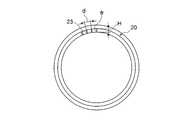
- a pulverizing apparatus comprises: A housing; A crushing table configured to rotate within the housing; A pulverizing apparatus provided on the outer peripheral side of the pulverizing table in the housing and including a throat for forming an upward airflow, The throat is An inner ring extending along the outer periphery of the grinding table; An outer ring provided on the outer peripheral side of the inner ring, and forming an annular flow path with the inner ring; A plurality of throat vanes provided between the inner ring and the outer ring; Including When the radial clearance between the inner ring and the outer ring is H, the length of the throat vane is L, and the distance between adjacent throat vanes is d, the following formulas (a) and (b) Meet. (A) 2.0 ⁇ L / d ⁇ 4.0 (B) 0.5 ⁇ H / d ⁇ 1.5
- the airflow is sufficiently contracted inside the throat, and the accelerated airflow is ejected from the upper surface of the grinding table.
- the crushed particles can be held on the throat by the kinetic energy of the accelerated airflow, and the fall from the throat can be suppressed.
- the gap H is a value determined approximately by the cross-sectional area of the throat. Therefore, H / d increases or decreases with the value of d, that is, the number of throat vanes.
- the fall amount can be suppressed by satisfying 0.5 ⁇ H / d.
- the number of throat vanes increases too much, the throat pressure loss increases. Therefore, an increase in pressure loss can be suppressed by satisfying H / d ⁇ 1.5. From the above, by satisfying the above formulas (a) and (b), it is possible to suppress an increase in the pressure loss of the airflow passing through the throat and suppress an increase in power of the pulverizing apparatus while suppressing the fall amount.
- the throat vane is inclined upstream from the lower end of the throat vane toward the upper end in the rotation direction of the throat,
- the following formula (c) is satisfied.
- (C) 45 ° ⁇ ⁇ ⁇ 60 °
- the throat vane is inclined toward the upstream side in the throat rotation direction from the lower end toward the upper end, so that the effect of scraping the pulverized particles by each throat vane increases. Further, by satisfying 45 ° ⁇ ⁇ , the pulverized particles can be effectively scooped up by the throat vane and the amount of fall can be suppressed.
- the value of L / d and H / d for realizing the amount of fall below the specified value can be reduced, and the throat peripheral portion of the pulverizer can be downsized. Moreover, the throat pressure loss can be suppressed by satisfying ⁇ ⁇ 60 °.
- the throat vane is inclined upstream from the lower end of the throat vane toward the upper end in the rotation direction of the throat,
- the inclination angle of the throat vane with respect to the rotation center axis of the throat is ⁇
- the following formula (d) is satisfied.
- the inner ring is located on the lower end side of the inner ring, has a shape curved toward the inner side in the radial direction toward the lower end of the inner ring, and rectifies the airflow flowing from below into the annular channel Including a rectifying unit. Since the airflow is supplied to the annular flow path from one side of the pulverizer, a flow rate deviation occurs along the circumferential direction of the throat. When the flow rate deviation occurs, the amount of fall at the part where the flow rate is low increases. According to the configuration (4), the flow rate deviation of the throat can be suppressed because the rectifying unit is provided, so that the fall amount can be made uniform along the circumferential direction of the throat.
- the peripheral speed of the crushing table is 3 m / s or more and 5 m / s or less.
- table peripheral speed the peripheral speed of the grinding table
- the centrifugal force acting on the object to be ground increases as the table circumferential speed increases, so the amount of ground particles moving from the grinding table to the throat Increases and the amount of fall increases.
- the table peripheral speed increases, the force with which the throat vane scoops up the pulverized particles increases, so the increase in the amount of fall decreases. Therefore, the drop amount converges to a constant amount as the table peripheral speed increases.
- the table peripheral speed By setting the table peripheral speed to 3 m / s or more, the crushing ability (capacity) can be ensured while converging the fall amount to a constant amount. Further, by setting the table peripheral speed to 5 m / s or less, an energy saving operation capable of avoiding an increase in power of the pulverizer is possible.
- a throat of a crushing device having any one of the constitutions (1) to (5),
- the throat is The inner ring;
- the outer ring provided on the outer peripheral side of the inner ring, and forming an annular channel with the inner ring;
- a plurality of the throat vanes provided between the inner ring and the outer ring; Including When the radial clearance between the inner ring and the outer ring is H, the length of the throat vane is L, and the interval between adjacent throat vanes is d, The following formulas (a) and (b) are satisfied.
- the amount of fall can be suppressed by satisfying 2.0 ⁇ L / d, and the airflow passing through the throat by satisfying L / d ⁇ 4.0.
- the pressure loss can be suppressed.
- the fall amount can be suppressed by satisfying 0.5 ⁇ H / d, and the pressure of the airflow passing through the throat by satisfying H / d ⁇ 1.5 (preferably H / d ⁇ 1.0). Loss can be suppressed.
- the pulverizing apparatus is configured to pulverize coal as an object to be pulverized. According to the configuration of (7) above, when the object to be crushed is coal, the pressure loss of the airflow passing through the throat can be suppressed while the amount of pulverized coal particles falling from the throat is suppressed.
- a pulverized coal fired boiler according to at least one embodiment of the present invention, A grinding device having the configuration of (7); A furnace for burning the pulverized coal obtained by the crusher; Is provided.
- the configuration of (8) in the pulverizing apparatus, it is possible to suppress the pressure loss of the carrier gas passing through the throat while suppressing the amount of pulverized coal particles falling from the throat.
- the maintenance of the crushing device is facilitated by suppressing the amount of fall, and the power increase of the crushing device can be suppressed by suppressing the pressure loss of the airflow.
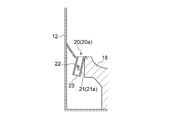
- (A) is a partially expanded sectional view of the throat part which concerns on one Embodiment
- (B) is a partially expanded sectional view of the throat part as a comparative example. It is a graph which shows the relationship between L / d and throat pressure loss. It is a graph which shows the relationship between L / d and the amount of drops from a throat. It is a graph which shows the relationship between H / d and throat pressure loss.
- an expression indicating that things such as “identical”, “equal”, and “homogeneous” are in an equal state not only represents an exactly equal state, but also has a tolerance or a difference that can provide the same function. It also represents the existing state.
- expressions representing shapes such as quadrangular shapes and cylindrical shapes represent not only geometrically strict shapes such as quadrangular shapes and cylindrical shapes, but also irregularities and chamfers as long as the same effects can be obtained. A shape including a part or the like is also expressed.
- the expressions “comprising”, “comprising”, “comprising”, “including”, or “having” one constituent element are not exclusive expressions for excluding the existence of other constituent elements.
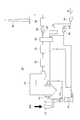
- FIG. 1 is a schematic front sectional view of a crushing apparatus according to an embodiment
- FIGS. 2 and 3 are front sectional views of a throat portion of the crushing apparatus according to the embodiment, respectively.
- the pulverization apparatus 10 includes a housing 12, and a pulverization unit 14 and a classification unit 16 provided inside the housing 12.
- the crushing unit 14 includes a crushing table 18 configured to rotate, and a throat 20 that is provided on the outer peripheral side of the crushing table 18 and that forms an updraft fu inside the housing 12.
- the object to be crushed supplied on the pulverization table 18 is pulverized, and the pulverized particles that have been pulverized into particles are accompanied by the rising air flow fu ejected from the throat 20, and the two phases of pulverized particles and air It rises as a stream.
- the pulverizing apparatus 10 includes a classification unit 16.
- the classifying unit 16 is provided above the crushing table 18 and is configured to classify the pulverized particles accompanying the rising air flow fu into fine particles Pm and coarse particles Pc.
- the fine particles Pm are sent together with the carrier gas through the classification unit 16 to the use destination, and the coarse particles Pc classified as the fine particles Pm return to the pulverization table 18.
- the throat 20 (20a, 20b) is provided on the outer ring side of the inner ring 21 and the inner ring 21 (21a, 21b) extending along the outer periphery of the crushing table 18, An outer ring 22 that forms an annular flow channel fr is provided between the inner ring 21 and the inner ring 21.
- the throat 20 includes a plurality of throat vanes 23 provided between the inner ring 21 and the outer ring 22.
- the throat 20 is expressed by the following formula (a) And (b). (A) 2.0 ⁇ L / d ⁇ 4.0
- the contraction effect of the airflow passing through the annular flow channel fr can be enhanced.
- the compressed and accelerated air flow is ejected from the upper surface of the pulverizing table, whereby the powder particles can be held on the throat by the kinetic energy of the air flow, and the amount of pulverized particles falling can be suppressed.
- L / d ⁇ 4.0 it is possible to suppress the throat pressure loss and suppress the increase in power of the pulverizer 10.
- d is smaller, the number of throat vanes 23 is increased and the number of times of scraping up the object to be crushed increases, so that the pulverized particles are less likely to fall from the throat.
- the fall amount can be suppressed by satisfying 0.5 ⁇ H / d.
- the processing of the crushed particles that fall is not in time, and the operation of the pulverizer 10 is hindered.
- the throat pressure loss increases. Therefore, satisfying H / d ⁇ 1.5 (preferably H / d ⁇ 1.0) increases the throat pressure loss.
- H / d ⁇ 1.5 preferably H / d ⁇ 1.0
- H / d ⁇ 1.5 increases the throat pressure loss.
- 5A shows a configuration example of the throat 20 that satisfies the expressions (a) and (b)
- FIG. 5B shows a configuration example of the throat 20 that does not satisfy the expressions (a) and (b). .
- FIG. 6 to 9 are graphs summarizing the knowledge obtained by the present inventors when the material to be crushed is coal.
- FIG. 6 shows the relationship between L / d and throat pressure loss
- FIG. 7 shows L / d and the amount of coal particles falling from the throat.
- FIG. 6 shows a low throat pressure loss when L / d is 2.0 or less, and shows that the throat pressure loss tends to increase from around 3.0 as L / d increases.
- the drop amount decreases as L / d increases, but when L / d becomes 3.0 or more, the drop amount does not decrease any more and the drop amount becomes substantially constant.
- L / d exceeds 4.0, the amount of fall shows an increasing tendency. From FIG. 6 and FIG.
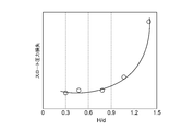
- FIG. 8 shows the relationship between H / d and throat pressure loss
- FIG. 9 shows H / d and the amount of coal particles falling from the throat.
- the throat pressure loss increases as H / d increases, but in the range of H / d ⁇ 1, the change in the throat pressure loss with respect to H / d is small.
- the throat pressure loss is substantially constant.
- the drop amount decreases as H / d increases.
- the fall amount can be reduced by setting 0.5 ⁇ H / d ⁇ 1.5, and preferably by setting H / d ⁇ 1.0, the throat pressure loss and It can be seen that both the amount of fall can be reduced.
- the inner ring 21 (21 b) of the throat 20 (20 b) includes a rectifying unit 52 formed in a lower end side region of the inner ring 21 (21 b).
- the rectifying unit 52 has a curved shape so as to approach the inner side in the radial direction toward the lower end of the inner ring 21 (21b).
- the rectifying unit 52 rectifies the air flow f flowing into the annular flow channel fr from below. Since the air flow f is supplied to the annular flow channel fr from one side surface of the crushing device 10, a flow rate deviation occurs along the circumferential direction of the throat 20. When the flow rate deviation occurs, the amount of fall at the part where the flow rate is low increases. According to the said structure, since it has the rectification
- a pulverized material supply pipe 24 into which the pulverized material Mr is charged and a fine particle discharging unit 26 for discharging the pulverized and classified fine particles Pm to the outside are provided.
- the fine particle discharge unit 26 is constituted by, for example, a tubular discharge pipe.
- the supply pipe 24 is vertically provided on the upper portion of the housing 12 such that the axis thereof is along the central axis O of the housing 12, and the object to be crushed Mr supplied from the supply pipe 24 is supplied onto the pulverization table 18.
- the supply pipe 24 is supported by the housing 12 via a bearing (not shown) so as to be rotatable in the direction of the arrow.
- the discharge part 26 is provided in the upper part of the classification part 16 so as to communicate with the classification part 16, and the fine particles Pm classified by the classification part 16 are discharged from the discharge part 26 to the outside.
- the pulverization unit 14 includes a pulverization table 18 and a pulverization roller 28 for pulverizing the object to be pulverized Mr.
- the pulverization object Mr. And crushed by biting.
- the crushing table 18 is rotated by a drive unit 30 that uses a motor 31 as a drive source.
- the object to be crushed Mr on the pulverizing table 18 is moved to the outer peripheral side on the pulverizing table 18 by the centrifugal force generated by the rotation of the pulverizing table 18, and is pulverized by the engagement between the pulverizing table 18 and the pulverizing roller 28.
- the crushing roller 28 is configured to be pressed against the crushing table 18 by a pressure device 32.
- An airflow formed by the carrier gas g supplied from the carrier gas duct 34 is ejected from the throat 20 into the housing 12.
- the carrier gas g is given a swirl along the circumferential direction of the housing by a plurality of throat vanes 23 provided in the throat 20 to form an upward air flow fu.
- the pulverized particles obtained by pulverizing the object to be pulverized Mr ascend with the ascending air flow fu formed by the carrier gas g and ascend the outer peripheral side region in the housing 12. During the ascending, a part of the coarse particles Pc contained in the pulverized particles falls by gravity classification and returns to the pulverization table 18.
- the classifying unit 16 includes an annular rotating unit 36 that can rotate about the central axis O of the housing 12.
- the annular rotating part 36 is attached to the supply pipe 24 and rotates together with the supply pipe 24.
- the annular rotating part 36 includes a plurality of rotating fins 38 arranged with a gap around the central axis O.
- a plurality of fixed fins 40 arranged in an annular shape with a gap around the central axis O are provided outside the annular rotating portion 36.
- a rectifying cone 42 is provided below the fixed fin 40.
- the plurality of rotating fins 40 are arranged directly facing a region in the internal space of the housing 12 where the ascending airflow fu exists.
- the hopper is not disposed at a height position between the annular rotating part 36 and the pulverizing part 14, and there is no member that blocks the airflow between the rotary fin 40 of the annular rotating part 36 and the pulverizing part 14. Therefore, the housing 12 can be made compact, and the coarse particles Pc that cannot pass through the classification unit 16 can be smoothly returned to the pulverization unit 14 from a region where the flow velocity of the ascending air fu is relatively slow.
- a motor 44 is provided on the upper surface of the housing 12, and the output of the motor 44 is configured to be transmitted to the supply pipe 24 via the speed reducer 46.
- the rotation of the motor 44 causes the annular rotating portion 36 to rotate about the central axis O together with the supply pipe 24.
- the throat vane 23 is inclined toward the upstream side in the rotational direction of the throat 20 from the lower end of the throat vane 23 toward the upper end. Moreover, when the inclination angle of the throat vane 23 with respect to the rotation center axis (center axis O) of the throat 20 is ⁇ , the following formula (c) is satisfied. (C) 45 ° ⁇ ⁇ ⁇ 60 ° According to the said structure, since the throat vane 23 inclines in the upstream of the rotation direction of the throat 20 toward the upper end from the lower end, the effect of scraping the pulverized particle P by each throat vane 23 increases.
- the effect of scraping the throat vane 23 on the pulverized particles P can be increased, so that the amount of fall can be suppressed.
- the values of L / d and H / d for realizing a fall amount equal to or less than a specified value can be reduced, and the throat peripheral portion of the crushing device 10 can be reduced in size.
- throat pressure loss can be suppressed by satisfying ⁇ ⁇ 60 °.
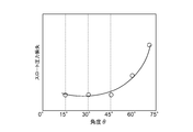
- FIG. 11 shows the relationship between ⁇ and throat pressure loss when the pulverized particles are coal particles
- FIG. 12 shows the relationship between ⁇ and the drop amount in the same case.
- FIG. 11 shows that when ⁇ is in the vicinity of 15 ° to 45 °, the throat pressure loss is at a low level, and as ⁇ increases from around 45 °, the throat pressure loss increases. However, when ⁇ ⁇ 60 °, the throat pressure loss increases. It shows that the increase can be suppressed.
- the drop amount decreases as ⁇ increases, but in the range of ⁇ ⁇ 45 °, the change in the drop amount with respect to ⁇ is small. From FIG. 11 and FIG. 12, when 45 ° ⁇ ⁇ ⁇ 60 °, both the throat pressure loss and the drop amount can be effectively reduced.
- the table peripheral speed is 3 m / s or more and 5 m / s or less.
- FIG. 13 shows the relationship between the table peripheral speed and the amount of pulverized particles falling.
- the centrifugal force acting on the object to be pulverized increases as the table peripheral speed increases, so the amount of pulverized particles moving from the pulverization table 18 to the throat 20 increases.
- the amount of fall increases.
- the table peripheral speed increases, the force of the throat vane 23 scooping up the pulverized particles increases, so the increase in the fall amount decreases. Therefore, as shown in FIG. 13, the amount of fall converges to a certain amount as the table peripheral speed increases.
- FIG. 14A shows the layer thickness D of the pulverized particles P when the table peripheral speed is low
- FIG. 14B shows the layer thickness D of the pulverized particles P when the table peripheral speed is high.
- the layer thickness D of the pulverized particles P becomes thicker inward in the radial direction of the pulverization table 18, and the layer thickness D near the throat is not constant.
- the layer thickness D in the vicinity of the throat 20 when the table peripheral speed is high converges to a constant value, so that the fall amount also converges to a constant amount.
- the crushing ability (capacity) can be ensured while converging the fall amount to a constant amount.
- operation which can avoid the motive power increase of the grinding
- the throat vane 23 is inclined upstream from the lower end of the throat vane 23 toward the upper end in the rotational direction of the throat 20 (the rotational direction of the crushing table 18). Further, the inclination angle ⁇ of the throat vane 23 satisfies the following formula (d). (D) H / d ⁇ 0.95 ⁇ (sin ⁇ ) ⁇ 2.0 ⁇ (L / d) ⁇ 1.2
- FIG. 15 is a graph showing the relationship between H / d, L / d, and ⁇ necessary to keep the fall amount within a desired range (a range smaller than the allowable fall amount).
- a desired range a range smaller than the allowable fall amount.
- the present inventors have increased H / d in order to realize a desired drop amount. It has been found that L / d can be reduced by reducing L / d, and H / d can be reduced by increasing L / d.
- the throat vane 23 can expect the effect of scooping up the pulverized particles. Even if it is small, a desired amount of fall can be realized.
- the length L of the throat vane is large with respect to the interval d between adjacent throat vanes, it is possible to suppress the falling of the pulverized particles by sufficiently constricting the air flow inside the throat. Can also achieve the desired drop amount.
- the throat 20 provided in the crushing device 10 is provided on the outer ring side of the inner ring 21 and the inner ring 21, and forms an annular flow channel fr between the inner ring 21 and the inner ring 21.
- a plurality of throat vanes 23 provided between the inner ring 21 and the outer ring 22.
- interval d of the throat vane 23 are comprised so that the said Formula (a) and (b) may be satisfy
- the amount of fall can be suppressed by satisfying 2.0 ⁇ L / d, and the pressure loss of the airflow passing through the throat can be reduced by satisfying L / d ⁇ 4.0. Can be suppressed.
- the fall amount can be suppressed by satisfying 0.5 ⁇ H / d
- the throat pressure loss can be suppressed by satisfying H / d ⁇ 1.5. Therefore, both the fall amount and the throat pressure loss can be reduced by satisfying the expressions (a) and (b).
- the pulverizer 10 is configured to pulverize coal as the material to be pulverized Mr. Accordingly, when the object to be pulverized Mr is coal, the pressure loss of the airflow passing through the throat 20 can be suppressed while the amount of pulverized coal particles falling from the throat 20 is suppressed.
- the pulverized coal burning boiler 60 includes a pulverizing apparatus 10 and a furnace (boiler body) 62 for burning the pulverized coal Cm obtained by the pulverizing apparatus 10.
- the air A is sent from the blower 64 to the pulverizer 10, and the coal as the raw material (the material to be pulverized Mr) is supplied from the coal bunker 70 and the coal feeder 72. .
- Combustion air A fed into the blower 64 is branched into the air A 1 and the air A 2.
- the air A 1 is conveyed to the grinding device 10 by the blower 66.
- Part of the air A 1 is conveyed to the grinding device 10 as being heated warm air by preheater 80.
- the warm air heated by the preheater 80 and the cold air directly conveyed from the blower 66 without passing through the preheater 80 are mixed and adjusted so that the mixed air has an appropriate temperature, and then the pulverizing apparatus 10. May be supplied.
- the air A 1 supplied to the pulverizing apparatus 10 is blown out from the throat 20 (see FIG. 1) into the housing 12 inside the pulverizing apparatus 10.
- Coal as the material to be pulverized Mr is fed into the coal bunker 70 and then supplied to the pulverizing apparatus 10 by the coal feeder 72 through the supply pipe 24 (see FIG. 1).
- the pulverized coal Cm generated by being pulverized by the pulverizing apparatus 10 while being dried by the air flow f of the air A 1 from the throat 20 is conveyed by the air A 1 from the discharge unit 26 (see FIG. 1), and the wind of the furnace 62 It is sent to the furnace 62 through a pulverized coal burner (not shown) in the box 74, and is ignited and burned by the burner.
- the air A 2 is heated by the preheater 68 and the preheater 80, sent to the furnace 62 through the wind box 74, and pulverized coal Cm in the furnace 62. Used for combustion.
- the exhaust gas generated by the combustion of the pulverized coal Cm in the furnace 62 is sent to the denitration device 78 after the dust is removed by the dust collector 66, and nitrogen oxides (NOx) contained in the exhaust gas are reduced.
- the exhaust gas is sucked by the blower 82 through the preheater 80, the sulfur content is removed by the desulfurization device 84, and released from the chimney 86 into the atmosphere.
- the coarse particles Pc classified as the pulverized coal Cm by the classification unit 16 of the pulverizing apparatus 10 can be smoothly returned to the pulverization table 18.
- the fineness of the pulverized coal Cm that has passed through the classification unit 16 can be improved, the pressure loss in the housing 12 can be reduced, and the increase in power of the crushing device 10 can be suppressed.
- the pulverized coal Cm in which the mixing of the coarse particles Pc is suppressed is combusted, it is possible to reduce air pollutants such as NOx in the combustion gas, and to reduce the unburned matter in the ash, thereby improving the boiler efficiency. Can be improved.
- the amount of pulverized particles falling from the throat can be suppressed, and the increase in power loss of the pulverizer can be suppressed by suppressing an increase in pressure loss in the housing. It can be suitably applied to a pulverizing apparatus provided in a boiler and pulverizing coal as an object to be crushed.
Landscapes
- Engineering & Computer Science (AREA)
- Food Science & Technology (AREA)
- Chemical & Material Sciences (AREA)
- Combustion & Propulsion (AREA)
- Mechanical Engineering (AREA)
- General Engineering & Computer Science (AREA)
- Crushing And Grinding (AREA)
Abstract
Priority Applications (4)
| Application Number | Priority Date | Filing Date | Title |
|---|---|---|---|
| MYPI2018702664A MY194648A (en) | 2016-02-09 | 2017-01-13 | Pulverizing device, throat for pulverizing device, and pulverized-coal fired boiler |
| US16/075,201 US10974251B2 (en) | 2016-02-09 | 2017-01-13 | Pulverizing device, throat for pulverizing device, and pulverized-coal fired boiler |
| KR1020187022601A KR102111226B1 (ko) | 2016-02-09 | 2017-01-13 | 분쇄 장치, 분쇄 장치의 스로트 및 미분탄 연소 보일러 |
| CN201780010176.7A CN108602069B (zh) | 2016-02-09 | 2017-01-13 | 粉碎装置、粉碎装置的喉管以及煤粉燃烧锅炉 |
Applications Claiming Priority (2)
| Application Number | Priority Date | Filing Date | Title |
|---|---|---|---|
| JP2016-022848 | 2016-02-09 | ||
| JP2016022848A JP6503307B2 (ja) | 2016-02-09 | 2016-02-09 | 粉砕装置、粉砕装置のスロート及び微粉炭焚きボイラ |
Publications (1)
| Publication Number | Publication Date |
|---|---|
| WO2017138295A1 true WO2017138295A1 (fr) | 2017-08-17 |
Family
ID=59562955
Family Applications (1)
| Application Number | Title | Priority Date | Filing Date |
|---|---|---|---|
| PCT/JP2017/000954 Ceased WO2017138295A1 (fr) | 2016-02-09 | 2017-01-13 | Dispositif de broyage, gorge pour dispositif de broyage et chaudière à charbon pulvérisé |
Country Status (6)
| Country | Link |
|---|---|
| US (1) | US10974251B2 (fr) |
| JP (1) | JP6503307B2 (fr) |
| KR (1) | KR102111226B1 (fr) |
| CN (1) | CN108602069B (fr) |
| MY (1) | MY194648A (fr) |
| WO (1) | WO2017138295A1 (fr) |
Families Citing this family (4)
| Publication number | Priority date | Publication date | Assignee | Title |
|---|---|---|---|---|
| JP6469343B2 (ja) * | 2013-12-13 | 2019-02-13 | 三菱日立パワーシステムズ株式会社 | 固体燃料粉砕装置および固体燃料粉砕装置の製造方法 |
| DK2985081T3 (en) * | 2014-08-12 | 2017-07-10 | Loesche Gmbh | Process and air flow vertical mill for grinding hot and humid raw material as well as duct-like segment. |
| CN110449224B (zh) * | 2019-08-09 | 2021-09-21 | 江苏吉能达环境能源科技有限公司 | 一种超微细粉立式辊碾磨粉机 |
| CN115672481B (zh) * | 2022-09-15 | 2025-06-27 | 北京电力设备总厂有限公司 | 一种磨煤机碾磨耦合装置及使用方法 |
Citations (4)
| Publication number | Priority date | Publication date | Assignee | Title |
|---|---|---|---|---|
| JPS62144548U (fr) * | 1986-03-04 | 1987-09-11 | ||
| JPH06226128A (ja) * | 1993-02-01 | 1994-08-16 | Babcock Hitachi Kk | ローラミル |
| JP2000093822A (ja) * | 1998-09-25 | 2000-04-04 | Loesche Gmbh | 空気スィ―プ式ロ―ラミル用のブレ―ドリング |
| US20140353411A1 (en) * | 2013-06-03 | 2014-12-04 | Alstom Technology Ltd. | Air flow control arrangement for pulverizer |
Family Cites Families (15)
| Publication number | Priority date | Publication date | Assignee | Title |
|---|---|---|---|---|
| US4264041A (en) * | 1979-09-28 | 1981-04-28 | The Babcock & Wilcox Co. | Low pressure drop pulverizer throat |
| CN85103743B (zh) * | 1985-05-16 | 1987-02-18 | 三菱重工业株式会社 | 固体原料的粉碎方法 |
| JPH0764603B2 (ja) * | 1986-12-23 | 1995-07-12 | 宇部興産株式会社 | 竪型ロ−ラミルによるセメントクリンカ−等の粉砕方法 |
| US4907751A (en) * | 1988-10-03 | 1990-03-13 | Sure Alloy Steel | Rotating throat for coal pulverizer |
| JPH1028890A (ja) * | 1996-07-16 | 1998-02-03 | Mitsubishi Heavy Ind Ltd | 竪型ローラミル |
| JPH10128140A (ja) | 1996-10-31 | 1998-05-19 | Ishikawajima Harima Heavy Ind Co Ltd | 竪型ミル |
| JP4550486B2 (ja) | 2004-05-13 | 2010-09-22 | バブコック日立株式会社 | 分級機およびそれを備えた竪型粉砕機、ならびにその竪型粉砕機を備えた石炭焚ボイラ装置 |
| TWI483787B (zh) * | 2007-09-27 | 2015-05-11 | 巴布考克日立股份有限公司 | A grading device and an upright pulverizing device having the classifying device and a coal fired boiler device |
| CN201375918Y (zh) * | 2009-03-11 | 2010-01-06 | 河南黎明路桥重工有限公司 | 低阻力悬辊磨曲面风道 |
| JP2011245357A (ja) * | 2010-05-21 | 2011-12-08 | Mitsubishi Heavy Ind Ltd | バイオマス粉砕装置及びバイオマス・石炭混焼システム |
| CN104329660A (zh) * | 2011-09-30 | 2015-02-04 | 三菱重工业株式会社 | 生物质粉碎装置及生物质/煤混烧系统 |
| JP2013103212A (ja) * | 2011-11-16 | 2013-05-30 | Babcock Hitachi Kk | 竪型粉砕装置およびそれを備えた石炭焚きボイラプラント |
| JP5927992B2 (ja) * | 2012-03-01 | 2016-06-01 | 株式会社Ihi | バイオマスミル |
| JP5791556B2 (ja) * | 2012-03-26 | 2015-10-07 | 三菱日立パワーシステムズ株式会社 | 竪型粉砕装置 |
| CN103203264B (zh) * | 2013-02-07 | 2015-07-01 | 洛阳矿山机械工程设计研究院有限责任公司 | 一种水泥原料矿渣的立式辊磨机气流装置及其气流输送方法 |
-
2016
- 2016-02-09 JP JP2016022848A patent/JP6503307B2/ja active Active
-
2017
- 2017-01-13 KR KR1020187022601A patent/KR102111226B1/ko active Active
- 2017-01-13 CN CN201780010176.7A patent/CN108602069B/zh active Active
- 2017-01-13 US US16/075,201 patent/US10974251B2/en active Active
- 2017-01-13 WO PCT/JP2017/000954 patent/WO2017138295A1/fr not_active Ceased
- 2017-01-13 MY MYPI2018702664A patent/MY194648A/en unknown
Patent Citations (4)
| Publication number | Priority date | Publication date | Assignee | Title |
|---|---|---|---|---|
| JPS62144548U (fr) * | 1986-03-04 | 1987-09-11 | ||
| JPH06226128A (ja) * | 1993-02-01 | 1994-08-16 | Babcock Hitachi Kk | ローラミル |
| JP2000093822A (ja) * | 1998-09-25 | 2000-04-04 | Loesche Gmbh | 空気スィ―プ式ロ―ラミル用のブレ―ドリング |
| US20140353411A1 (en) * | 2013-06-03 | 2014-12-04 | Alstom Technology Ltd. | Air flow control arrangement for pulverizer |
Also Published As
| Publication number | Publication date |
|---|---|
| US20180372313A1 (en) | 2018-12-27 |
| KR20180100639A (ko) | 2018-09-11 |
| JP2017140567A (ja) | 2017-08-17 |
| US10974251B2 (en) | 2021-04-13 |
| JP6503307B2 (ja) | 2019-04-17 |
| MY194648A (en) | 2022-12-09 |
| KR102111226B1 (ko) | 2020-05-14 |
| CN108602069B (zh) | 2020-02-28 |
| CN108602069A (zh) | 2018-09-28 |
Similar Documents
| Publication | Publication Date | Title |
|---|---|---|
| JP4550486B2 (ja) | 分級機およびそれを備えた竪型粉砕機、ならびにその竪型粉砕機を備えた石炭焚ボイラ装置 | |
| JP5812668B2 (ja) | 回転式分級機 | |
| JP4865865B2 (ja) | 分級装置及びそれを備えた竪型粉砕装置ならびに石炭焚ボイラ装置 | |
| JP6629605B2 (ja) | 分級機、粉砕分級装置及び微粉炭焚きボイラ | |
| WO2017138295A1 (fr) | Dispositif de broyage, gorge pour dispositif de broyage et chaudière à charbon pulvérisé | |
| KR20180100637A (ko) | 분급기, 분쇄 분급 장치 및 미분탄 연소 보일러 | |
| WO2017138294A1 (fr) | Dispositif de broyage et chaudière à charbon pulvérisé | |
| JP2742066B2 (ja) | 回転分級式微粉砕機 | |
| JP2004290726A (ja) | 分級機及びそれを備えた竪型粉砕機、石炭焚ボイラ装置 | |
| JP2018111080A (ja) | 分級機、竪型粉砕機及び石炭焚ボイラ | |
| JPS62102841A (ja) | 竪型ミル |
Legal Events
| Date | Code | Title | Description |
|---|---|---|---|
| 121 | Ep: the epo has been informed by wipo that ep was designated in this application |
Ref document number: 17750020 Country of ref document: EP Kind code of ref document: A1 |
|
| ENP | Entry into the national phase |
Ref document number: 20187022601 Country of ref document: KR Kind code of ref document: A |
|
| WWE | Wipo information: entry into national phase |
Ref document number: 1020187022601 Country of ref document: KR |
|
| NENP | Non-entry into the national phase |
Ref country code: DE |
|
| 122 | Ep: pct application non-entry in european phase |
Ref document number: 17750020 Country of ref document: EP Kind code of ref document: A1 |