WO2017141380A1 - Couvercle - Google Patents
Couvercle Download PDFInfo
- Publication number
- WO2017141380A1 WO2017141380A1 PCT/JP2016/054601 JP2016054601W WO2017141380A1 WO 2017141380 A1 WO2017141380 A1 WO 2017141380A1 JP 2016054601 W JP2016054601 W JP 2016054601W WO 2017141380 A1 WO2017141380 A1 WO 2017141380A1
- Authority
- WO
- WIPO (PCT)
- Prior art keywords
- container
- lid
- main body
- wall
- valve
- Prior art date
- Legal status (The legal status is an assumption and is not a legal conclusion. Google has not performed a legal analysis and makes no representation as to the accuracy of the status listed.)
- Ceased
Links
Images




Classifications
-
- B—PERFORMING OPERATIONS; TRANSPORTING
- B65—CONVEYING; PACKING; STORING; HANDLING THIN OR FILAMENTARY MATERIAL
- B65D—CONTAINERS FOR STORAGE OR TRANSPORT OF ARTICLES OR MATERIALS, e.g. BAGS, BARRELS, BOTTLES, BOXES, CANS, CARTONS, CRATES, DRUMS, JARS, TANKS, HOPPERS, FORWARDING CONTAINERS; ACCESSORIES, CLOSURES, OR FITTINGS THEREFOR; PACKAGING ELEMENTS; PACKAGES
- B65D51/00—Closures not otherwise provided for
- B65D51/16—Closures not otherwise provided for with means for venting air or gas
-
- B—PERFORMING OPERATIONS; TRANSPORTING
- B65—CONVEYING; PACKING; STORING; HANDLING THIN OR FILAMENTARY MATERIAL
- B65D—CONTAINERS FOR STORAGE OR TRANSPORT OF ARTICLES OR MATERIALS, e.g. BAGS, BARRELS, BOTTLES, BOXES, CANS, CARTONS, CRATES, DRUMS, JARS, TANKS, HOPPERS, FORWARDING CONTAINERS; ACCESSORIES, CLOSURES, OR FITTINGS THEREFOR; PACKAGING ELEMENTS; PACKAGES
- B65D53/00—Sealing or packing elements; Sealings formed by liquid or plastics material
- B65D53/02—Collars or rings
Definitions
- the present invention relates to a lid for closing the inside of a container body in a storage container for storing and storing the container that needs to be vented (hereinafter simply referred to as “container”) in the container body. More specifically, the present invention relates to a lid that has a simple and compact structure, but that is capable of suppressing contact with externally contained air and degassing the contained material.
- a lid body that seals the opening of the container body of the storage container in an airtight state is provided, and by providing a gas venting structure in this lid body, air inflow from the outside into the storage container is prevented.
- a first technique is known that discharges gas from the contents stored in the container body, for example, carbon dioxide generated from roasted coffee beans or ground powder to the outside (for example, Patent Documents). 1).
- the contents come into contact with the invading air, and the quality deteriorates due to the progress of oxidation and wetting, or the internal pressure in the storage container is higher than the outside air pressure due to the gas generated from the contents. It is possible to prevent the container from being deformed or ruptured.
- a space (hereinafter referred to as “open space”) is created in the upper part of the container body, but the consumption of the contents has progressed and opened.
- the space is greatly expanded, a large amount of air in the container body is replaced with outside air every time the storage container is opened. For this reason, if the storage period is long, the stored item comes into contact with the substituted air for a long time, and the quality of the stored item is greatly deteriorated.
- the bottom plate on which the contents are placed can be moved up and down in the container body, and the bottom plate is lifted to the opening side by the amount consumed, so that the space between the contents and the lid body is increased.
- a second technique for reducing the generated open space in accordance with the consumption of the contents is known (for example, see Patent Document 2).
- the container body is sealed and the open space is released. It is conceivable to reduce the quality of the stored items by reducing the size of the stored items.
- JP 2002-34458 A Utility Model Registration No. 3076298
- a female thread portion is formed on the inner surface of the cap-shaped lid, while a cylindrical portion that protrudes from the container body and has an opening at the tip is formed. It is provided that a male screw portion is formed on the outer peripheral surface of the tip of the cylindrical portion, and the above-described lid body is screwed into the cylindrical portion for mounting.
- the sealing structure of the container body is not always simple.
- the processing cost for forming the cylindrical portion and each screw portion is high.
- it is indispensable to apply a sealing material to the female thread portion of the lid and the cost of the parts also increases.
- a careful screwing operation is indispensable for mounting the lid, it takes time and time to store and store the contents, and the mounting workability of the lid is inferior.
- the degassing structure of the contents is a valve hole provided in a film stretched in the through hole of the substrate part of the lid, and a valve piece for degassing is fixed to the valve hole so that it can be opened and closed by heat welding or the like. is there. For this reason, since the number of parts increases, the part cost is further increased, and a large installation space is required, resulting in an increase in the size of the lid.
- a rotating shaft with a screw cut is supported on the shaft center in the bottomed cylindrical container body opened upward, and this rotation is performed.
- a disk-shaped support plate is fixed to the upper end of the shaft, and a disk-shaped bottom plate is screwed to the lower end of the rotating shaft so as to be movable in the axial direction of the rotating shaft.
- the reduction structure of the open space is not always simple, and the number of parts is large and the part cost is further increased. Furthermore, in order to move the bottom plate in the axial direction, the rotation operation of the support plate described above is required. Therefore, it takes time and effort to reduce the open space, and the mounting workability of the lid further deteriorates.
- the present invention was devised in view of the above points, and it is possible to suppress the contact of air from outside with the contained material and to reliably vent the contained material while having a simple and compact structure.
- An object is to provide a lid.
- the lid of the present invention is inserted into a container main body for storing the contents to be degassed and placed on the container in the container main body.
- a lid main body part that forms a communication gap communicating with the outside, and an inner dimension of the container inner wall from the outer periphery of the main body part of the lid main body part in plan view
- the outer periphery of the closing part protruding outward by a predetermined amount is elastically in contact with the inner wall of the container to close the inside of the container body on the container, and the elastic closing part is in a closed state.
- a valve structure in which a predetermined pressure receiving portion bends preferentially toward the opening side of the container main body and opens due to a pressure receiving area difference of the pressure receiving portion on which the gas pressure in the container main body acts.
- the lid main body portion placed on the container within the container main body simplifies the structure, reduces the component cost, and the lid body.
- the mounting workability can be improved.
- the lid main body part is directly brought into contact with the contents to function as a so-called “drop lid”, so that the open space does not expand even if the contents are consumed, and the conventional screwing structure, shaft
- the support structure and the rotation operation for moving the bottom plate on which the contents are placed when the lid is mounted can be omitted.
- the cost of parts can be further reduced by the lid body part that forms a communication gap communicating with the outside between the container body wall and the container inner wall. That is, the gas flowing out through the valve structure can be discharged to the outside using this communication gap, and it is not necessary to provide a special exhaust path separately, and the number of parts can be reduced.
- the outer periphery of the closed portion that is provided continuously to the lid main body portion and projects outward from the outer periphery of the main body portion of the lid main body portion by a predetermined amount from the inner dimension of the inner wall of the container in a plan view is elastic to the inner wall of the container.
- the structure is simplified, the component cost is reduced, and the lid mounting workability is further improved. Can proceed. That is, by simply mounting the lid on the container body so that the elastic blocking portion faces the inside of the container body, the elastic blocking section of the lid body can block the inside of the container body in an airtight state. Structures, machining operations such as threading, separate members such as sealing materials for airtightness, and careful screwing operations can be omitted.
- a conventional gas-provided valve can be formed with a simple structure in which a pressure-receiving area difference is provided in the pressure-receiving portion of the elastic blockage and a valve function is imparted to the predetermined pressure-receiving portion. It is possible to reduce the number of parts and to reduce the installation space by omitting a complicated structure in which the valve piece for venting gas is fixed to the hole so as to be opened and closed by heat welding or the like.
- valve structure has a valve portion whose area is larger than the surroundings among the pressure receiving portions due to a gap amount difference of a communication gap formed between the outer periphery of the main body portion and the inner wall of the container, Only by utilizing the difference between the planar view shape of the outer periphery of the main body and the planar view shape of the inner wall of the container, a pressure receiving area difference can be easily provided in the pressure receiving portion. Thereby, it is not necessary to perform complicated processing on the elastic blocking portion or to incorporate a special member in order to provide a pressure receiving area difference, and it is possible to further reduce the component cost.
- the inner wall of the container is formed in a substantially rectangular shape
- the outer periphery of the main body is formed in a substantially circular shape or a substantially elliptical shape having a smaller diameter than the inner wall of the container.
- the inner wall of the container is formed in a substantially circular shape or a substantially elliptic shape
- the outer periphery of the main body portion is formed in a substantially rectangular shape having a smaller diameter than the inner wall of the container.
- the lid main body portion has a bottom surface of the main body portion in which a bottom recess into which the storage object enters is formed, and the elastic blockage is provided at a distal end of a convex edge portion that is an outer edge of the bottom recess and protrudes into the storage material.
- the sliding resistance of the lid main body part on the accommodation can be increased by the bottom surface of the main body part in which the bottom recess into which the accommodation enters.
- the lid placed in the shape of a drop lid slides on the container due to shaking or tilting of the storage container and is greatly separated from a specific part of the inner wall of the container. It is possible to reliably prevent the occurrence of an excessive gap between the container and the inner wall of the container, and to stabilize the blockage in the container body.
- the elastic closing portion is fixed by the amount of the object pushed in at the tip of the convex edge portion.
- the outer periphery of the closing part is pushed out to the valve opening side by the contained material.
- the lid main body portion has a handle that forms an air vent gap between the inner wall of the container and the outer periphery of the closed portion by gripping and rotating on the container, only the grip rotation operation of the handle, It is possible to easily break the airtightness in the container body by communicating the inside and outside of the lid. Thereby, the cover body in which the container side is in an airtight state can be pulled out with a small force, and the opening workability of the cover body can be improved.
- the outer periphery of the closing part when the outer periphery of the closing part is formed in the same size and shape as the inner wall of the container, the outer periphery of the closing part may protrude excessively from the inner wall of the container.
- the protruding portion can prevent the air vent gap from being covered when the lid main body rotates. Thereby, the further improvement of lid opening workability
- valve portion has at least one of a thin-walled structure that is thinner than the surrounding elastic blocking portion and a composite structure that has a larger elastic deformability than the surrounding elastic closing portion, the pressure receiving pressure on which the gas pressure acts In addition to the pressure receiving area difference of the portion, the bending rigidity of the valve portion itself can be set low. Thereby, the operation sensitivity of the valve structure with respect to the gas pressure in the storage container can be increased, and the gas can be surely vented even if the gas release from the stored item is slight.
- the lid according to the present invention has a simple and compact structure, it is possible to reliably suppress contact with the air containing material from the outside and degas the containing material.
- FIG. 1 is a perspective view showing an overall configuration of a storage container to which an inner lid that is a lid according to the present invention is attached
- FIG. 1A is a perspective view showing an appearance in a state in which an inner lid and an outer lid are attached
- (B) is an exploded perspective view showing the appearance of the state where the inner lid and the outer lid are removed from the container body.
- FIG. 2A is a perspective view of the inner lid
- FIG. 2B is a plan view
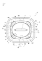
- FIG. 2C is a bottom view. It is a top view in the state where the inner lid was mounted in the container body.
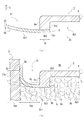
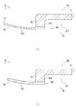
- FIG. 4A is a side sectional view of the outer peripheral portion of the inner lid other than the valve portion, where FIG.
- FIG. 4A is a sectional view taken along the line XX in FIG. 2B, and FIG. 4B is an xx arrow in FIG.
- FIG. 5A is a side sectional view of the outer peripheral portion of the inner lid in the valve portion
- FIG. 5A is a sectional view taken along the arrow YY in FIG. 2B
- FIG. 5B is a sectional view taken along the arrow yy in FIG. It is sectional drawing. It is side surface sectional drawing of the outer peripheral part of the inner cover in the valve part at the time of valve opening operation
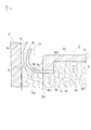
- FIG. 8A is a side cross-sectional view of an outer peripheral portion of an inner lid having a valve portion of another form
- FIG. 8A is a side cross-sectional view of a valve portion having a thin structure
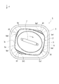
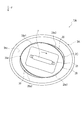
- FIG. 8B is a view of a valve portion having a composite structure. It is side surface sectional drawing. It is a figure which shows the structure of the inner lid of another form, Comprising: Fig.9 (a) is a top view similarly, FIG.9 (b) is a top view in the state with which the container main body was similarly mounted
- the direction indicated by the arrow F in FIG. 1 is the front
- the direction indicated by the arrow U is the upper side
- the position and direction of each part described below are based on the front and the upper side.
- the storage container 1 includes a bottomed rectangular cylindrical container body 3 having an opening 3a opened upward, an inner lid 2 that is inserted into the container body 3 and placed on a container 5 such as coffee beans, And an outer lid 4 that is detachably attached to the opening 3a after being placed.
- the container body 3 includes an inner space 6 surrounded by a bottom surface 3b having a substantially rectangular shape in plan view and a container inner wall 3c having a substantially rectangular shape in plan view that forms four peripheries above the bottom surface 3b.
- the internal space 6 is composed of an empty space 6b that is above the inner lid 2 and extends between the outer lid 4 and an accommodation space 6a that is below the inner lid 2.
- the container 5 that needs to be degassed is packed densely.
- the container main body 3 becomes thinner as it approaches the bottom surface 3b from the opening 3a, and along with this, the container inner wall 3c also shrinks in a substantially similar shape in plan view, but on the bottom surface 3b that shrinks to the smallest diameter. Also, the dimensions of the container inner wall 3c are set so that the inner lid 2 can be inserted and placed.
- the inner lid 2 can be always placed on the container 5 in the container body 3 until the container 5 is consumed and used up.
- the container body 3 of this embodiment is made of ceramic having a thickness of about 5 mm, but may be a metal such as stainless steel or aluminum, glass, synthetic resin, wood, etc. If it is a thing suitable for, the structure and raw material of the container main body 3 will not be specifically limited.
- the inner lid 2 includes a lid main body portion 8 in which a handle 7 that is gripped by a hand and performs an attaching / detaching operation of the inner lid 2 is protruded from a substantially central portion of the upper surface, and a main body bottom surface that is a lower surface of the lid main body portion 8.
- a substantially ring-shaped sheet 9 that is fixed so as to be connected to 8b and can close the inside of the container main body 3 on the container 5 is provided.
- the lid body 8 is also made of a ceramic having a thickness of about 7 mm in this embodiment, but it may be made of metal such as stainless steel or aluminum, glass, synthetic resin, wood, etc., similar to the container body 3.
- the structure and material of the lid body 8 are not particularly limited as long as they are suitable for preserving the containing material 5 that generates gas.
- the sheet 9 is formed of an elastic body such as silicon rubber or chloroprene rubber, and the outer peripheral portion 9a that is the outer periphery of the closing portion is substantially rectangular in a plan view, and the inner dimension of the container inner wall 3c of the container main body 3 is. It is formed in a large diameter so as to be outside by a predetermined overhang amount.
- an elastic body such as silicon rubber or chloroprene rubber
- the outer lid 4 is made of ceramic like the container main body 3 and the lid main body portion 8 described above, and has a substantially rectangular plate-shaped main body portion 4a having a concave portion 4a1 opened upward on the upper surface, and the main body.
- the fitting portion 4b is smaller in diameter than the portion 4a and has a substantially rectangular plate shape in plan view.
- the main body 4a protrudes outside the inner dimension of the opening inner wall 3a1 of the opening 3a, and when the outer lid 4 is attached to the opening 3a, the lower surface of the outer peripheral portion 4a2 of the main body 4a is the opening 3a.
- the opening 3 a is covered with the outer lid 4 in contact with the upper edge 3 a 2.
- the fitting part 4b is inside the inner dimension of the opening inner wall 3a1, and when the outer lid 4 is mounted on the opening 3a, the fitting part 4b is inserted into the opening 3a.
- the outer lid 4 can be easily removed from the opening 3a by pulling up the lower surface of the outer peripheral portion 4a2 and the aforementioned concave portion 4a1 while sandwiching it between a plurality of fingertips.
- an exhaust hole (not shown) is formed from the fitting portion 4b to the main body portion 4a.
- the outer lid 4 only needs to have such a sealing function and a gas discharge function, and its structure and material are not particularly limited. Further, when the storage container 1 is placed at a low risk of intrusion of dust from the outside as in a refrigerator or a storage, the outer lid 4 itself can be omitted.
- the inner lid 2 includes a valve structure 11 formed in the seat 9 in addition to the lid body 8 and the seat 9 described above. Below, the structure of each part is explained in full detail.
- the inner lid 2 is inserted into the container body 3 and placed on the container 5 as described above, and consumes the container 5. Until it is used up.
- the lid body 8 can be brought into direct contact with the container 5 and the function as a so-called “drop lid” can always be exhibited, and the above-described open space can be expanded even if the container 5 is consumed. There is nothing.
- the outer peripheral portion 8a which is the outer periphery of the main body portion constituting the outer periphery of the lid main body portion 8 is different from the aforementioned container inner wall 3c and has a substantially elliptical shape in plan view that is long in the left-right direction, and from the inner dimension of the container inner wall 3c. Is also formed with a small diameter so as to be inside by a predetermined gap amount.
- a communication gap 15 that communicates with the above-described empty space 6 b outside the inner lid 2 can be provided between the container inner wall 3 c of the container body 3 and the outer peripheral portion 8 a of the lid body 8.
- a bottom concave portion 8b1 that opens downward is formed in the bottom surface portion 8b of the lid main body portion 8, and the convex edge portion 8b2 that is an outer edge surrounding the outer periphery of the bottom concave portion 8b1 is formed in the lower container 5 It is protruding. And the sheet
- a long anchor 31 is formed on the left and right at the substantially central portion of the bottom recess 8b1 when viewed from the bottom, and this anchor 31 is also protruded into the container 5 below.
- the outer periphery 9a of the seat 9 is pushed upward by the container 5 by the amount of the container 5 pushed in by the lower surface 8b3 of the convex edge 8b2. For this reason, the stroke until the valve opening in the valve structure 11 described in detail later is shortened, the operation time is shortened, and the operation speed of the valve structure 11 can be increased.
- the sheet 9 has a substantially ring shape, and as described above, the outer peripheral portion 9a is formed in a substantially rectangular shape in plan view larger than the inner dimension of the container inner wall 3c in plan view.
- the peripheral portion 9b is formed in a substantially elliptical shape in plan view that is reduced to a substantially similar shape from the outer peripheral portion 8a of the lid body portion 8 that is substantially elliptical in plan view.
- the inner peripheral portion 9b of the sheet 9 can be provided with a sticking allowance 16 having a substantially constant radial width over the entire circumference, and the sticking allowance 16 is attached to the main body bottom face 8b, so that the circumferential direction Regardless of the position, the sheet 9 can be adhered with a uniform adhesive force, and local peeling can be suppressed and the peeling strength of the sheet 9 can be increased.
- the lower surface 8b3 of the bottom surface 8b of the main body is also formed so that the radial width is substantially constant over the entire circumference, whereby the inner peripheral portion 9b of the sheet 9 is formed on the entire surface of the lower surface 8b3.
- the radial width of the pasting margin 16 can be made substantially constant over the entire circumference, the inner peripheral portion 9b of the sheet 9 can be easily processed, and the processing cost can be reduced.
- the end surface of the outer peripheral portion 9a of the sheet 9 is formed in an R shape that is curved upward in a sectional view.
- the outer peripheral portion 9a of the sheet 9 can be brought into contact with the container inner wall 3c without any gap even if the shape and size of the container inner wall 3c vary greatly in the circumferential direction.
- the airtightness of the container main body 3 by the sheet 9, more specifically, the accommodation space 6a is further improved.
- the inside of the container main body 3 in the closed state is formed in a portion (hereinafter referred to as “pressure receiving portion”) 9 c that protrudes outside the lower surface 8 b 3 of the lid main body portion 8 with the sheet 9.
- the gas pressure in the accommodation space 6a acts.
- the outer peripheral portion 8a of the lid main body portion 8 is substantially elliptical in plan view, whereas the outer peripheral portion 9a of the sheet 9 protruding outward from the lid main body portion 8 is elastically applied.
- the container inner wall 3c that comes into contact is formed in a substantially rectangular shape in plan view.
- the gap 14a in the portion 9c1 (hereinafter referred to as “valve portion”) indicated by hatching in the vicinity of the four corners of the container inner wall 3c in the pressure receiving portion 9c is the other pressure receiving portion (hereinafter “ It can be set to be larger than the gap amount 14b in 9c2.
- valve structure 11 in which the valve portion 9c1 is bent preferentially to the opening 3a side by the gas pressure, and the gas venting structure is formed with a simple configuration. By eliminating the structure, it is possible to reduce the number of parts and the installation space.
- the outer peripheral portion 9a of the sheet 9 projecting outward from the lid main body 8 has a substantially rectangular shape in plan view, and the container inner wall 3c having a substantially rectangular shape in plan view is enlarged to a substantially similar shape. It is.
- the protruding amount 10a from the container inner wall 3c in the valve portion 9c1 and the protruding amount 10b from the container inner wall 3c in the closed portion 9c2 are substantially equal.
- the contact length 17a of the portion that contacts the container inner wall 3c at the valve portion 9c1 is set to be substantially the same as the contact length 17b of the portion that contacts the container inner wall 3c at the closed portion 9c2. It is possible to secure a substantially uniform contact length regardless of the circumferential position, and to reduce the occlusive variation in the circumferential direction due to the sheet 9.
- the gap amount of the communication gap 15 is set larger in the valve portion 9 c 1 than in the closed portion 9 c 2, and the difference in the gap amount is different from that of the outer peripheral portion 8 a of the lid main body portion 8. It is generated by forming the container inner wall 3c of the container body 3 in different shapes in plan view.
- valve structure 11 when gas is generated from the container 5 after the inner lid 2 is placed on the container 5, the outer peripheral portion 9 a is in contact with the container inner wall 3 c and bent upward. Gas pressure acts on the lower surface of the valve portion 9c1, and the valve portion 9c1 is further bent upward with a bending line 9d as a connection boundary line with the lid body 8 as shown in FIGS. Is done.
- a discharge gap 18 is formed between the valve portion 9c1 and the container inner wall 3c, and the gas generated from the stored material 5 passes through this discharge gap 18 from the storage space 6a to the empty space 6b as shown by an arrow 19. And then discharged to the outside through an exhaust hole (not shown) of the outer lid 4.
- the container inner wall 3c is formed in a substantially rectangular shape in plan view
- the outer peripheral portion 8a of the lid body 8 is formed in a substantially elliptical shape in plan view having a smaller diameter than the container inner wall 3c.
- the valve portion 9c1 is set to the pressure receiving portion 9c in the vicinity of the four corners of the container inner wall 3c.
- each valve part 9c1 can be shortened compared with the case where the valve part 9c1 is set in the vicinity of the side part of the container inner wall 3c, and the valve opening force required for opening the valve part 9c1.
- the operating sensitivity of the valve structure 11 with respect to the gas pressure in the storage container 1 can be further increased.
- the inside and outside of the inner lid 2 are communicated with each other through the air vent gap 20, and the airtightness in the accommodation space 6 a filled with the contents 5 can be easily broken. Then, even if the inside space 6a is kept at a large negative pressure by the elastic force of the seat 9 because the inner lid 2 is pushed in strongly, the inner lid 2 can be applied with a small force only by the gripping and rotating operation of the handle 7. The lid opening workability of the inner lid 2 is improved.
- the outer peripheral portion 9a of the sheet 9 has a substantially rectangular shape in plan view, and the container inner wall 3c having a substantially rectangular shape in plan view is enlarged to a substantially similar shape.
- 9a and the container inner wall 3c are formed in substantially the same shape, and both the above-described overhangs 10a and 10b are set small, and the outer peripheral portion 9a and the container inner wall 3c are formed in substantially the same size. .
- the inner lid 2A is configured such that the thickness of the valve portion 9c1 of the seat 9 of the inner lid 2 described above is smaller than the thickness of the surrounding pressure receiving portion. The bending rigidity of the valve portion 9c1 is reduced.
- the thickness of the valve portion 9A1 in the seat 9A is 21, which is set to be smaller than the surrounding pressure receiving portion having the same thickness 22 as the valve portion 9c1 of the seat 9, and the valve portion 9A1
- the valve portion 9c1 can be easily bent and opened with a gas pressure smaller than that of the valve portion 9c1.
- the inner lid 2B changes the valve portion 9c1 of the seat 9 of the inner lid 2 to another material having a larger elastic deformability than the surroundings.
- the bending rigidity of the valve portion is reduced.
- the valve portion 9B1 of the seat 9B is made of, for example, soft silicone rubber in which soft silicone rubber is mixed with normal silicone rubber so that the bending rigidity is smaller than that of the surrounding pressure receiving portion.
- the portion 9B1 can be easily bent and opened with a gas pressure smaller than that of the aforementioned valve portion 9c1.
- the bending rigidity of the valve portions 9A1 and 9B1 itself can be set low in addition to the area difference of the pressure receiving portion where the gas pressure acts, and the operation sensitivity of the valve portion with respect to the gas pressure in the storage container 1 can be set. Can be increased.
- the storage container 1A has a plan view shape of the outer peripheral portion 8a of the lid main body portion 8 of the inner lid 2 and the inner wall 3c of the container main body 3 described above. By changing, the position and shape of the valve portion 9c1 are changed.
- the outer peripheral portion 28a of the lid main body 28 is substantially rectangular in plan view, and the container of the container main body 3A with which the outer peripheral portion 29a of the sheet 29 projecting outward from the lid main body 28 elastically contacts.
- the inner wall 3Ac is formed in a substantially elliptical shape in plan view.
- the aforementioned communication gap 15 communicating with the empty space 6b outside the inner lid 2C can also be provided between the container inner wall 3Ac of the container body 3A and the outer peripheral portion 28a of the lid body 28.
- valve portions 29 c 1 and 29 c 2 having large gap amounts 23 a and 23 b are formed in the pressure receiving portion 29 c of the seat 29 in the hatched portions near the sides of the outer peripheral portion 28 a of the lid main body 28.
- a closed portion 29c3 having a gap amount 23c smaller than the gap amounts 23a and 23b is formed.
- valve portions 29c1 and 29c2 also have a pressure receiving area larger than that of the surroundings, so that the valve structure 11A that preferentially bends and opens to the opening 3a side by the gas pressure is formed like the valve portion 9c1 described above. can do.
- the bent line 29d of the valve portions 29c1 and 29c2 is longer than the bent line 9d of the valve portion 9c1 described above, and the valve opening force is larger than that of the valve portion 9c1.
- the valve portions 29c1 and 29c2 are opened when the amount of gas generated from the container 5 is small and it is not necessary to vent the gas so much. The number of valves can be reduced appropriately.
- the lid body 28 is also formed with a handle 7 at a substantially central portion on the upper surface, and the inner lid 2 ⁇ / b> C is rotated clockwise in plan view on the container 5 while holding the handle 7.
- the outer peripheral portion 29a having a substantially elliptical shape in plan view
- the pair of outer peripheral portions 29a1 and 29a1 facing each other across the center in plan view ride on the inner wall 3Ac of the container. In this manner, while rising upward, an air vent gap 30 indicated by hatching is formed between the other pair of outer peripheral portions 29a2, 29a2 and the container inner wall 3Ac.
- the inner and outer sides of the inner lid 2C are communicated through the air vent gap 30, and the airtightness in the accommodating space 6a filled with the contents 5 can be easily broken.
- the opening workability of the lid 2C is improved.
- the outer peripheral portion 29a of the sheet 29 has a substantially elliptic shape in plan view
- the container inner wall 3Ac having a substantially elliptic shape in plan view is enlarged in a substantially similar shape in plan view.
- the portion 29a and the container inner wall 3Ac are formed to have substantially the same shape and substantially the same size.
- the outer peripheral portion 8a of the lid main body 8 and the container inner wall 3Ac of the container main body 3A are both formed in a substantially elliptical shape in plan view, but may be substantially circular.
- the shape is not particularly limited as long as a gap amount difference is generated in the communication gap 15 in the pressure receiving portions 9c and 29c.
- the lid to which the present invention is applied has a simple and compact structure, and can reliably suppress contact with air from the outside and degas the contained material. ing.
Landscapes
- Engineering & Computer Science (AREA)
- Mechanical Engineering (AREA)
- Closures For Containers (AREA)
Abstract
L'objectif de la présente invention est de concevoir un couvercle qui présente une structure simple et compacte tout en assurant la suppression du contact entre l'air extérieur et un article stocké et l'évacuation du gaz provenant de l'article stocké. Un couvercle intérieur (2) auquel la présente invention est appliquée comprend : une partie corps de couvercle (8) qui est insérée dans un corps de récipient (3) contenant un article stocké (5) nécessitant une évacuation de gaz et est placée au-dessus de l'article stocké (5) dans le corps de récipient (3), un espace de communication (15) qui communique avec l'extérieur étant formé entre la partie de corps de couvercle (8) et une paroi intérieure de récipient (3c) du corps de récipient (3) ; une feuille (9) qui est disposée de façon contiguë à la partie corps de couvercle (8), une partie périphérique extérieure (9a) qui, dans une vue en plan, fait saillie vers l'extérieur depuis une partie périphérique extérieure (8a) de la partie corps de couvercle (8) dans une mesure prescrite au-delà des dimensions intérieures de la paroi intérieure de récipient (3c), entrant en contact élastique avec la paroi intérieure de récipient (3c) et assurant une isolation vis-à-vis de l'intérieur du corps de récipient (3) situé au-dessus de l'article stocké (5) ; et une structure formant valve (11). En raison de la différence de surface de réception de pression d'une partie de réception de pression (9c) sur laquelle agit la pression du gaz à l'intérieur du corps de récipient (3) qui est dans un état isolé par la feuille (9), une partie valve (9c1) qui est une partie de réception de pression prescrite fléchit de préférence vers une ouverture (3a) du corps de récipient (3) et s'ouvre.
Priority Applications (1)
| Application Number | Priority Date | Filing Date | Title |
|---|---|---|---|
| PCT/JP2016/054601 WO2017141380A1 (fr) | 2016-02-17 | 2016-02-17 | Couvercle |
Applications Claiming Priority (1)
| Application Number | Priority Date | Filing Date | Title |
|---|---|---|---|
| PCT/JP2016/054601 WO2017141380A1 (fr) | 2016-02-17 | 2016-02-17 | Couvercle |
Publications (1)
| Publication Number | Publication Date |
|---|---|
| WO2017141380A1 true WO2017141380A1 (fr) | 2017-08-24 |
Family
ID=59624861
Family Applications (1)
| Application Number | Title | Priority Date | Filing Date |
|---|---|---|---|
| PCT/JP2016/054601 Ceased WO2017141380A1 (fr) | 2016-02-17 | 2016-02-17 | Couvercle |
Country Status (1)
| Country | Link |
|---|---|
| WO (1) | WO2017141380A1 (fr) |
Citations (9)
| Publication number | Priority date | Publication date | Assignee | Title |
|---|---|---|---|---|
| US3164289A (en) * | 1962-12-14 | 1965-01-05 | Thomas A Cocchiarella | Hermetically sealable container lid |
| JPS492681A (fr) * | 1972-04-27 | 1974-01-10 | ||
| US3924774A (en) * | 1972-10-11 | 1975-12-09 | John H Donnelly | Closure for containers |
| GB2074974A (en) * | 1980-05-07 | 1981-11-11 | Allbrighton S E | Container Sealing Device |
| JPH02135463U (fr) * | 1988-12-21 | 1990-11-09 | ||
| JPH068236U (ja) * | 1992-07-08 | 1994-02-01 | 英治 新原 | 食品容器用蓋 |
| DE29504252U1 (de) * | 1995-03-11 | 1995-06-29 | Radak, Radostav, 46485 Wesel | Aromadose |
| US20070215624A1 (en) * | 2006-03-20 | 2007-09-20 | Smallwood Dale O | Self air evacuating system |
| JP3177563U (ja) * | 2012-05-29 | 2012-08-09 | 坤樹 林 | 密閉容器 |
-
2016
- 2016-02-17 WO PCT/JP2016/054601 patent/WO2017141380A1/fr not_active Ceased
Patent Citations (9)
| Publication number | Priority date | Publication date | Assignee | Title |
|---|---|---|---|---|
| US3164289A (en) * | 1962-12-14 | 1965-01-05 | Thomas A Cocchiarella | Hermetically sealable container lid |
| JPS492681A (fr) * | 1972-04-27 | 1974-01-10 | ||
| US3924774A (en) * | 1972-10-11 | 1975-12-09 | John H Donnelly | Closure for containers |
| GB2074974A (en) * | 1980-05-07 | 1981-11-11 | Allbrighton S E | Container Sealing Device |
| JPH02135463U (fr) * | 1988-12-21 | 1990-11-09 | ||
| JPH068236U (ja) * | 1992-07-08 | 1994-02-01 | 英治 新原 | 食品容器用蓋 |
| DE29504252U1 (de) * | 1995-03-11 | 1995-06-29 | Radak, Radostav, 46485 Wesel | Aromadose |
| US20070215624A1 (en) * | 2006-03-20 | 2007-09-20 | Smallwood Dale O | Self air evacuating system |
| JP3177563U (ja) * | 2012-05-29 | 2012-08-09 | 坤樹 林 | 密閉容器 |
Similar Documents
| Publication | Publication Date | Title |
|---|---|---|
| EP3480130B1 (fr) | Récipient de décharge | |
| US9731887B2 (en) | Rubber seal for vacuum receptacle and lid for the receptacle using the same | |
| JP2016513050A (ja) | 真空容器用チェックバルブ及びこれを用いた真空容器蓋 | |
| CN106864973B (zh) | 食品容器 | |
| JP6084504B2 (ja) | 注出容器 | |
| EP1538107A2 (fr) | Valve unidirectionnelle pour récipients hermétiques | |
| US20120248110A1 (en) | Airtight container | |
| JPWO2007037081A1 (ja) | 圧縮袋用の脱気弁及び脱気弁を備えた圧縮袋 | |
| KR20210041771A (ko) | 내부 가스 배출이 용이한 컵뚜껑 | |
| JP2018122860A (ja) | 積層剥離容器 | |
| JP5271574B2 (ja) | 化粧料容器 | |
| WO2017141380A1 (fr) | Couvercle | |
| KR100856933B1 (ko) | 진공형성을 위한 커버부재를 가진 진공용기 | |
| JP6858451B2 (ja) | 吐出容器 | |
| KR20110052267A (ko) | 진공 패킹이 설치된 진공 용기 | |
| JP2022541437A (ja) | 真空バルブを有する食品真空保管容器用マルチプッシュボタン | |
| KR102015281B1 (ko) | 휴대용 진공보관용기 | |
| JP6629124B2 (ja) | 吐出容器 | |
| US20080190933A1 (en) | Sealing Closure Device For a Container | |
| JP6392473B2 (ja) | 蓋体 | |
| JP3140080U (ja) | 流動物等の多用途収納容器 | |
| KR101988969B1 (ko) | 압력 조절 기능을 갖는 식품보관용기 및 식품보관용기 제조방법 | |
| JP2007217031A (ja) | 気密容器 | |
| JP3224712U (ja) | 保存容器用密閉構造及び保存容器 | |
| US20170327293A1 (en) | Flexible vacuum sealing adapter for use with food storage systems and methods of use |
Legal Events
| Date | Code | Title | Description |
|---|---|---|---|
| 121 | Ep: the epo has been informed by wipo that ep was designated in this application |
Ref document number: 16890522 Country of ref document: EP Kind code of ref document: A1 |
|
| NENP | Non-entry into the national phase |
Ref country code: DE |
|
| 122 | Ep: pct application non-entry in european phase |
Ref document number: 16890522 Country of ref document: EP Kind code of ref document: A1 |
|
| NENP | Non-entry into the national phase |
Ref country code: JP |