WO2017141380A1 - 蓋体 - Google Patents
蓋体 Download PDFInfo
- Publication number
- WO2017141380A1 WO2017141380A1 PCT/JP2016/054601 JP2016054601W WO2017141380A1 WO 2017141380 A1 WO2017141380 A1 WO 2017141380A1 JP 2016054601 W JP2016054601 W JP 2016054601W WO 2017141380 A1 WO2017141380 A1 WO 2017141380A1
- Authority
- WO
- WIPO (PCT)
- Prior art keywords
- container
- lid
- main body
- wall
- valve
- Prior art date
- Legal status (The legal status is an assumption and is not a legal conclusion. Google has not performed a legal analysis and makes no representation as to the accuracy of the status listed.)
- Ceased
Links
Images




Classifications
-
- B—PERFORMING OPERATIONS; TRANSPORTING
- B65—CONVEYING; PACKING; STORING; HANDLING THIN OR FILAMENTARY MATERIAL
- B65D—CONTAINERS FOR STORAGE OR TRANSPORT OF ARTICLES OR MATERIALS, e.g. BAGS, BARRELS, BOTTLES, BOXES, CANS, CARTONS, CRATES, DRUMS, JARS, TANKS, HOPPERS, FORWARDING CONTAINERS; ACCESSORIES, CLOSURES, OR FITTINGS THEREFOR; PACKAGING ELEMENTS; PACKAGES
- B65D51/00—Closures not otherwise provided for
- B65D51/16—Closures not otherwise provided for with means for venting air or gas
-
- B—PERFORMING OPERATIONS; TRANSPORTING
- B65—CONVEYING; PACKING; STORING; HANDLING THIN OR FILAMENTARY MATERIAL
- B65D—CONTAINERS FOR STORAGE OR TRANSPORT OF ARTICLES OR MATERIALS, e.g. BAGS, BARRELS, BOTTLES, BOXES, CANS, CARTONS, CRATES, DRUMS, JARS, TANKS, HOPPERS, FORWARDING CONTAINERS; ACCESSORIES, CLOSURES, OR FITTINGS THEREFOR; PACKAGING ELEMENTS; PACKAGES
- B65D53/00—Sealing or packing elements; Sealings formed by liquid or plastics material
- B65D53/02—Collars or rings
Definitions
- the present invention relates to a lid for closing the inside of a container body in a storage container for storing and storing the container that needs to be vented (hereinafter simply referred to as “container”) in the container body. More specifically, the present invention relates to a lid that has a simple and compact structure, but that is capable of suppressing contact with externally contained air and degassing the contained material.
- a lid body that seals the opening of the container body of the storage container in an airtight state is provided, and by providing a gas venting structure in this lid body, air inflow from the outside into the storage container is prevented.
- a first technique is known that discharges gas from the contents stored in the container body, for example, carbon dioxide generated from roasted coffee beans or ground powder to the outside (for example, Patent Documents). 1).
- the contents come into contact with the invading air, and the quality deteriorates due to the progress of oxidation and wetting, or the internal pressure in the storage container is higher than the outside air pressure due to the gas generated from the contents. It is possible to prevent the container from being deformed or ruptured.
- a space (hereinafter referred to as “open space”) is created in the upper part of the container body, but the consumption of the contents has progressed and opened.
- the space is greatly expanded, a large amount of air in the container body is replaced with outside air every time the storage container is opened. For this reason, if the storage period is long, the stored item comes into contact with the substituted air for a long time, and the quality of the stored item is greatly deteriorated.
- the bottom plate on which the contents are placed can be moved up and down in the container body, and the bottom plate is lifted to the opening side by the amount consumed, so that the space between the contents and the lid body is increased.
- a second technique for reducing the generated open space in accordance with the consumption of the contents is known (for example, see Patent Document 2).
- the container body is sealed and the open space is released. It is conceivable to reduce the quality of the stored items by reducing the size of the stored items.
- JP 2002-34458 A Utility Model Registration No. 3076298
- a female thread portion is formed on the inner surface of the cap-shaped lid, while a cylindrical portion that protrudes from the container body and has an opening at the tip is formed. It is provided that a male screw portion is formed on the outer peripheral surface of the tip of the cylindrical portion, and the above-described lid body is screwed into the cylindrical portion for mounting.
- the sealing structure of the container body is not always simple.
- the processing cost for forming the cylindrical portion and each screw portion is high.
- it is indispensable to apply a sealing material to the female thread portion of the lid and the cost of the parts also increases.
- a careful screwing operation is indispensable for mounting the lid, it takes time and time to store and store the contents, and the mounting workability of the lid is inferior.
- the degassing structure of the contents is a valve hole provided in a film stretched in the through hole of the substrate part of the lid, and a valve piece for degassing is fixed to the valve hole so that it can be opened and closed by heat welding or the like. is there. For this reason, since the number of parts increases, the part cost is further increased, and a large installation space is required, resulting in an increase in the size of the lid.
- a rotating shaft with a screw cut is supported on the shaft center in the bottomed cylindrical container body opened upward, and this rotation is performed.
- a disk-shaped support plate is fixed to the upper end of the shaft, and a disk-shaped bottom plate is screwed to the lower end of the rotating shaft so as to be movable in the axial direction of the rotating shaft.
- the reduction structure of the open space is not always simple, and the number of parts is large and the part cost is further increased. Furthermore, in order to move the bottom plate in the axial direction, the rotation operation of the support plate described above is required. Therefore, it takes time and effort to reduce the open space, and the mounting workability of the lid further deteriorates.
- the present invention was devised in view of the above points, and it is possible to suppress the contact of air from outside with the contained material and to reliably vent the contained material while having a simple and compact structure.
- An object is to provide a lid.
- the lid of the present invention is inserted into a container main body for storing the contents to be degassed and placed on the container in the container main body.
- a lid main body part that forms a communication gap communicating with the outside, and an inner dimension of the container inner wall from the outer periphery of the main body part of the lid main body part in plan view
- the outer periphery of the closing part protruding outward by a predetermined amount is elastically in contact with the inner wall of the container to close the inside of the container body on the container, and the elastic closing part is in a closed state.
- a valve structure in which a predetermined pressure receiving portion bends preferentially toward the opening side of the container main body and opens due to a pressure receiving area difference of the pressure receiving portion on which the gas pressure in the container main body acts.
- the lid main body portion placed on the container within the container main body simplifies the structure, reduces the component cost, and the lid body.
- the mounting workability can be improved.
- the lid main body part is directly brought into contact with the contents to function as a so-called “drop lid”, so that the open space does not expand even if the contents are consumed, and the conventional screwing structure, shaft
- the support structure and the rotation operation for moving the bottom plate on which the contents are placed when the lid is mounted can be omitted.
- the cost of parts can be further reduced by the lid body part that forms a communication gap communicating with the outside between the container body wall and the container inner wall. That is, the gas flowing out through the valve structure can be discharged to the outside using this communication gap, and it is not necessary to provide a special exhaust path separately, and the number of parts can be reduced.
- the outer periphery of the closed portion that is provided continuously to the lid main body portion and projects outward from the outer periphery of the main body portion of the lid main body portion by a predetermined amount from the inner dimension of the inner wall of the container in a plan view is elastic to the inner wall of the container.
- the structure is simplified, the component cost is reduced, and the lid mounting workability is further improved. Can proceed. That is, by simply mounting the lid on the container body so that the elastic blocking portion faces the inside of the container body, the elastic blocking section of the lid body can block the inside of the container body in an airtight state. Structures, machining operations such as threading, separate members such as sealing materials for airtightness, and careful screwing operations can be omitted.
- a conventional gas-provided valve can be formed with a simple structure in which a pressure-receiving area difference is provided in the pressure-receiving portion of the elastic blockage and a valve function is imparted to the predetermined pressure-receiving portion. It is possible to reduce the number of parts and to reduce the installation space by omitting a complicated structure in which the valve piece for venting gas is fixed to the hole so as to be opened and closed by heat welding or the like.
- valve structure has a valve portion whose area is larger than the surroundings among the pressure receiving portions due to a gap amount difference of a communication gap formed between the outer periphery of the main body portion and the inner wall of the container, Only by utilizing the difference between the planar view shape of the outer periphery of the main body and the planar view shape of the inner wall of the container, a pressure receiving area difference can be easily provided in the pressure receiving portion. Thereby, it is not necessary to perform complicated processing on the elastic blocking portion or to incorporate a special member in order to provide a pressure receiving area difference, and it is possible to further reduce the component cost.
- the inner wall of the container is formed in a substantially rectangular shape
- the outer periphery of the main body is formed in a substantially circular shape or a substantially elliptical shape having a smaller diameter than the inner wall of the container.
- the inner wall of the container is formed in a substantially circular shape or a substantially elliptic shape
- the outer periphery of the main body portion is formed in a substantially rectangular shape having a smaller diameter than the inner wall of the container.
- the lid main body portion has a bottom surface of the main body portion in which a bottom recess into which the storage object enters is formed, and the elastic blockage is provided at a distal end of a convex edge portion that is an outer edge of the bottom recess and protrudes into the storage material.
- the sliding resistance of the lid main body part on the accommodation can be increased by the bottom surface of the main body part in which the bottom recess into which the accommodation enters.
- the lid placed in the shape of a drop lid slides on the container due to shaking or tilting of the storage container and is greatly separated from a specific part of the inner wall of the container. It is possible to reliably prevent the occurrence of an excessive gap between the container and the inner wall of the container, and to stabilize the blockage in the container body.
- the elastic closing portion is fixed by the amount of the object pushed in at the tip of the convex edge portion.
- the outer periphery of the closing part is pushed out to the valve opening side by the contained material.
- the lid main body portion has a handle that forms an air vent gap between the inner wall of the container and the outer periphery of the closed portion by gripping and rotating on the container, only the grip rotation operation of the handle, It is possible to easily break the airtightness in the container body by communicating the inside and outside of the lid. Thereby, the cover body in which the container side is in an airtight state can be pulled out with a small force, and the opening workability of the cover body can be improved.
- the outer periphery of the closing part when the outer periphery of the closing part is formed in the same size and shape as the inner wall of the container, the outer periphery of the closing part may protrude excessively from the inner wall of the container.
- the protruding portion can prevent the air vent gap from being covered when the lid main body rotates. Thereby, the further improvement of lid opening workability
- valve portion has at least one of a thin-walled structure that is thinner than the surrounding elastic blocking portion and a composite structure that has a larger elastic deformability than the surrounding elastic closing portion, the pressure receiving pressure on which the gas pressure acts In addition to the pressure receiving area difference of the portion, the bending rigidity of the valve portion itself can be set low. Thereby, the operation sensitivity of the valve structure with respect to the gas pressure in the storage container can be increased, and the gas can be surely vented even if the gas release from the stored item is slight.
- the lid according to the present invention has a simple and compact structure, it is possible to reliably suppress contact with the air containing material from the outside and degas the containing material.
- FIG. 1 is a perspective view showing an overall configuration of a storage container to which an inner lid that is a lid according to the present invention is attached
- FIG. 1A is a perspective view showing an appearance in a state in which an inner lid and an outer lid are attached
- (B) is an exploded perspective view showing the appearance of the state where the inner lid and the outer lid are removed from the container body.
- FIG. 2A is a perspective view of the inner lid
- FIG. 2B is a plan view
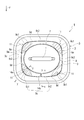
- FIG. 2C is a bottom view. It is a top view in the state where the inner lid was mounted in the container body.
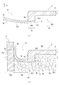
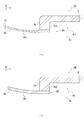
- FIG. 4A is a side sectional view of the outer peripheral portion of the inner lid other than the valve portion, where FIG.
- FIG. 4A is a sectional view taken along the line XX in FIG. 2B, and FIG. 4B is an xx arrow in FIG.
- FIG. 5A is a side sectional view of the outer peripheral portion of the inner lid in the valve portion
- FIG. 5A is a sectional view taken along the arrow YY in FIG. 2B
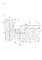
- FIG. 5B is a sectional view taken along the arrow yy in FIG. It is sectional drawing. It is side surface sectional drawing of the outer peripheral part of the inner cover in the valve part at the time of valve opening operation
- FIG. 8A is a side cross-sectional view of an outer peripheral portion of an inner lid having a valve portion of another form
- FIG. 8A is a side cross-sectional view of a valve portion having a thin structure
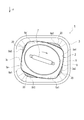
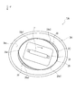
- FIG. 8B is a view of a valve portion having a composite structure. It is side surface sectional drawing. It is a figure which shows the structure of the inner lid of another form, Comprising: Fig.9 (a) is a top view similarly, FIG.9 (b) is a top view in the state with which the container main body was similarly mounted
- the direction indicated by the arrow F in FIG. 1 is the front
- the direction indicated by the arrow U is the upper side
- the position and direction of each part described below are based on the front and the upper side.
- the storage container 1 includes a bottomed rectangular cylindrical container body 3 having an opening 3a opened upward, an inner lid 2 that is inserted into the container body 3 and placed on a container 5 such as coffee beans, And an outer lid 4 that is detachably attached to the opening 3a after being placed.
- the container body 3 includes an inner space 6 surrounded by a bottom surface 3b having a substantially rectangular shape in plan view and a container inner wall 3c having a substantially rectangular shape in plan view that forms four peripheries above the bottom surface 3b.
- the internal space 6 is composed of an empty space 6b that is above the inner lid 2 and extends between the outer lid 4 and an accommodation space 6a that is below the inner lid 2.
- the container 5 that needs to be degassed is packed densely.
- the container main body 3 becomes thinner as it approaches the bottom surface 3b from the opening 3a, and along with this, the container inner wall 3c also shrinks in a substantially similar shape in plan view, but on the bottom surface 3b that shrinks to the smallest diameter. Also, the dimensions of the container inner wall 3c are set so that the inner lid 2 can be inserted and placed.
- the inner lid 2 can be always placed on the container 5 in the container body 3 until the container 5 is consumed and used up.
- the container body 3 of this embodiment is made of ceramic having a thickness of about 5 mm, but may be a metal such as stainless steel or aluminum, glass, synthetic resin, wood, etc. If it is a thing suitable for, the structure and raw material of the container main body 3 will not be specifically limited.
- the inner lid 2 includes a lid main body portion 8 in which a handle 7 that is gripped by a hand and performs an attaching / detaching operation of the inner lid 2 is protruded from a substantially central portion of the upper surface, and a main body bottom surface that is a lower surface of the lid main body portion 8.
- a substantially ring-shaped sheet 9 that is fixed so as to be connected to 8b and can close the inside of the container main body 3 on the container 5 is provided.
- the lid body 8 is also made of a ceramic having a thickness of about 7 mm in this embodiment, but it may be made of metal such as stainless steel or aluminum, glass, synthetic resin, wood, etc., similar to the container body 3.
- the structure and material of the lid body 8 are not particularly limited as long as they are suitable for preserving the containing material 5 that generates gas.
- the sheet 9 is formed of an elastic body such as silicon rubber or chloroprene rubber, and the outer peripheral portion 9a that is the outer periphery of the closing portion is substantially rectangular in a plan view, and the inner dimension of the container inner wall 3c of the container main body 3 is. It is formed in a large diameter so as to be outside by a predetermined overhang amount.
- an elastic body such as silicon rubber or chloroprene rubber
- the outer lid 4 is made of ceramic like the container main body 3 and the lid main body portion 8 described above, and has a substantially rectangular plate-shaped main body portion 4a having a concave portion 4a1 opened upward on the upper surface, and the main body.
- the fitting portion 4b is smaller in diameter than the portion 4a and has a substantially rectangular plate shape in plan view.
- the main body 4a protrudes outside the inner dimension of the opening inner wall 3a1 of the opening 3a, and when the outer lid 4 is attached to the opening 3a, the lower surface of the outer peripheral portion 4a2 of the main body 4a is the opening 3a.
- the opening 3 a is covered with the outer lid 4 in contact with the upper edge 3 a 2.
- the fitting part 4b is inside the inner dimension of the opening inner wall 3a1, and when the outer lid 4 is mounted on the opening 3a, the fitting part 4b is inserted into the opening 3a.
- the outer lid 4 can be easily removed from the opening 3a by pulling up the lower surface of the outer peripheral portion 4a2 and the aforementioned concave portion 4a1 while sandwiching it between a plurality of fingertips.
- an exhaust hole (not shown) is formed from the fitting portion 4b to the main body portion 4a.
- the outer lid 4 only needs to have such a sealing function and a gas discharge function, and its structure and material are not particularly limited. Further, when the storage container 1 is placed at a low risk of intrusion of dust from the outside as in a refrigerator or a storage, the outer lid 4 itself can be omitted.
- the inner lid 2 includes a valve structure 11 formed in the seat 9 in addition to the lid body 8 and the seat 9 described above. Below, the structure of each part is explained in full detail.
- the inner lid 2 is inserted into the container body 3 and placed on the container 5 as described above, and consumes the container 5. Until it is used up.
- the lid body 8 can be brought into direct contact with the container 5 and the function as a so-called “drop lid” can always be exhibited, and the above-described open space can be expanded even if the container 5 is consumed. There is nothing.
- the outer peripheral portion 8a which is the outer periphery of the main body portion constituting the outer periphery of the lid main body portion 8 is different from the aforementioned container inner wall 3c and has a substantially elliptical shape in plan view that is long in the left-right direction, and from the inner dimension of the container inner wall 3c. Is also formed with a small diameter so as to be inside by a predetermined gap amount.
- a communication gap 15 that communicates with the above-described empty space 6 b outside the inner lid 2 can be provided between the container inner wall 3 c of the container body 3 and the outer peripheral portion 8 a of the lid body 8.
- a bottom concave portion 8b1 that opens downward is formed in the bottom surface portion 8b of the lid main body portion 8, and the convex edge portion 8b2 that is an outer edge surrounding the outer periphery of the bottom concave portion 8b1 is formed in the lower container 5 It is protruding. And the sheet
- a long anchor 31 is formed on the left and right at the substantially central portion of the bottom recess 8b1 when viewed from the bottom, and this anchor 31 is also protruded into the container 5 below.
- the outer periphery 9a of the seat 9 is pushed upward by the container 5 by the amount of the container 5 pushed in by the lower surface 8b3 of the convex edge 8b2. For this reason, the stroke until the valve opening in the valve structure 11 described in detail later is shortened, the operation time is shortened, and the operation speed of the valve structure 11 can be increased.
- the sheet 9 has a substantially ring shape, and as described above, the outer peripheral portion 9a is formed in a substantially rectangular shape in plan view larger than the inner dimension of the container inner wall 3c in plan view.
- the peripheral portion 9b is formed in a substantially elliptical shape in plan view that is reduced to a substantially similar shape from the outer peripheral portion 8a of the lid body portion 8 that is substantially elliptical in plan view.
- the inner peripheral portion 9b of the sheet 9 can be provided with a sticking allowance 16 having a substantially constant radial width over the entire circumference, and the sticking allowance 16 is attached to the main body bottom face 8b, so that the circumferential direction Regardless of the position, the sheet 9 can be adhered with a uniform adhesive force, and local peeling can be suppressed and the peeling strength of the sheet 9 can be increased.
- the lower surface 8b3 of the bottom surface 8b of the main body is also formed so that the radial width is substantially constant over the entire circumference, whereby the inner peripheral portion 9b of the sheet 9 is formed on the entire surface of the lower surface 8b3.
- the radial width of the pasting margin 16 can be made substantially constant over the entire circumference, the inner peripheral portion 9b of the sheet 9 can be easily processed, and the processing cost can be reduced.
- the end surface of the outer peripheral portion 9a of the sheet 9 is formed in an R shape that is curved upward in a sectional view.
- the outer peripheral portion 9a of the sheet 9 can be brought into contact with the container inner wall 3c without any gap even if the shape and size of the container inner wall 3c vary greatly in the circumferential direction.
- the airtightness of the container main body 3 by the sheet 9, more specifically, the accommodation space 6a is further improved.
- the inside of the container main body 3 in the closed state is formed in a portion (hereinafter referred to as “pressure receiving portion”) 9 c that protrudes outside the lower surface 8 b 3 of the lid main body portion 8 with the sheet 9.
- the gas pressure in the accommodation space 6a acts.
- the outer peripheral portion 8a of the lid main body portion 8 is substantially elliptical in plan view, whereas the outer peripheral portion 9a of the sheet 9 protruding outward from the lid main body portion 8 is elastically applied.
- the container inner wall 3c that comes into contact is formed in a substantially rectangular shape in plan view.
- the gap 14a in the portion 9c1 (hereinafter referred to as “valve portion”) indicated by hatching in the vicinity of the four corners of the container inner wall 3c in the pressure receiving portion 9c is the other pressure receiving portion (hereinafter “ It can be set to be larger than the gap amount 14b in 9c2.
- valve structure 11 in which the valve portion 9c1 is bent preferentially to the opening 3a side by the gas pressure, and the gas venting structure is formed with a simple configuration. By eliminating the structure, it is possible to reduce the number of parts and the installation space.
- the outer peripheral portion 9a of the sheet 9 projecting outward from the lid main body 8 has a substantially rectangular shape in plan view, and the container inner wall 3c having a substantially rectangular shape in plan view is enlarged to a substantially similar shape. It is.
- the protruding amount 10a from the container inner wall 3c in the valve portion 9c1 and the protruding amount 10b from the container inner wall 3c in the closed portion 9c2 are substantially equal.
- the contact length 17a of the portion that contacts the container inner wall 3c at the valve portion 9c1 is set to be substantially the same as the contact length 17b of the portion that contacts the container inner wall 3c at the closed portion 9c2. It is possible to secure a substantially uniform contact length regardless of the circumferential position, and to reduce the occlusive variation in the circumferential direction due to the sheet 9.
- the gap amount of the communication gap 15 is set larger in the valve portion 9 c 1 than in the closed portion 9 c 2, and the difference in the gap amount is different from that of the outer peripheral portion 8 a of the lid main body portion 8. It is generated by forming the container inner wall 3c of the container body 3 in different shapes in plan view.
- valve structure 11 when gas is generated from the container 5 after the inner lid 2 is placed on the container 5, the outer peripheral portion 9 a is in contact with the container inner wall 3 c and bent upward. Gas pressure acts on the lower surface of the valve portion 9c1, and the valve portion 9c1 is further bent upward with a bending line 9d as a connection boundary line with the lid body 8 as shown in FIGS. Is done.
- a discharge gap 18 is formed between the valve portion 9c1 and the container inner wall 3c, and the gas generated from the stored material 5 passes through this discharge gap 18 from the storage space 6a to the empty space 6b as shown by an arrow 19. And then discharged to the outside through an exhaust hole (not shown) of the outer lid 4.
- the container inner wall 3c is formed in a substantially rectangular shape in plan view
- the outer peripheral portion 8a of the lid body 8 is formed in a substantially elliptical shape in plan view having a smaller diameter than the container inner wall 3c.
- the valve portion 9c1 is set to the pressure receiving portion 9c in the vicinity of the four corners of the container inner wall 3c.
- each valve part 9c1 can be shortened compared with the case where the valve part 9c1 is set in the vicinity of the side part of the container inner wall 3c, and the valve opening force required for opening the valve part 9c1.
- the operating sensitivity of the valve structure 11 with respect to the gas pressure in the storage container 1 can be further increased.
- the inside and outside of the inner lid 2 are communicated with each other through the air vent gap 20, and the airtightness in the accommodation space 6 a filled with the contents 5 can be easily broken. Then, even if the inside space 6a is kept at a large negative pressure by the elastic force of the seat 9 because the inner lid 2 is pushed in strongly, the inner lid 2 can be applied with a small force only by the gripping and rotating operation of the handle 7. The lid opening workability of the inner lid 2 is improved.
- the outer peripheral portion 9a of the sheet 9 has a substantially rectangular shape in plan view, and the container inner wall 3c having a substantially rectangular shape in plan view is enlarged to a substantially similar shape.
- 9a and the container inner wall 3c are formed in substantially the same shape, and both the above-described overhangs 10a and 10b are set small, and the outer peripheral portion 9a and the container inner wall 3c are formed in substantially the same size. .
- the inner lid 2A is configured such that the thickness of the valve portion 9c1 of the seat 9 of the inner lid 2 described above is smaller than the thickness of the surrounding pressure receiving portion. The bending rigidity of the valve portion 9c1 is reduced.
- the thickness of the valve portion 9A1 in the seat 9A is 21, which is set to be smaller than the surrounding pressure receiving portion having the same thickness 22 as the valve portion 9c1 of the seat 9, and the valve portion 9A1
- the valve portion 9c1 can be easily bent and opened with a gas pressure smaller than that of the valve portion 9c1.
- the inner lid 2B changes the valve portion 9c1 of the seat 9 of the inner lid 2 to another material having a larger elastic deformability than the surroundings.
- the bending rigidity of the valve portion is reduced.
- the valve portion 9B1 of the seat 9B is made of, for example, soft silicone rubber in which soft silicone rubber is mixed with normal silicone rubber so that the bending rigidity is smaller than that of the surrounding pressure receiving portion.
- the portion 9B1 can be easily bent and opened with a gas pressure smaller than that of the aforementioned valve portion 9c1.
- the bending rigidity of the valve portions 9A1 and 9B1 itself can be set low in addition to the area difference of the pressure receiving portion where the gas pressure acts, and the operation sensitivity of the valve portion with respect to the gas pressure in the storage container 1 can be set. Can be increased.
- the storage container 1A has a plan view shape of the outer peripheral portion 8a of the lid main body portion 8 of the inner lid 2 and the inner wall 3c of the container main body 3 described above. By changing, the position and shape of the valve portion 9c1 are changed.
- the outer peripheral portion 28a of the lid main body 28 is substantially rectangular in plan view, and the container of the container main body 3A with which the outer peripheral portion 29a of the sheet 29 projecting outward from the lid main body 28 elastically contacts.
- the inner wall 3Ac is formed in a substantially elliptical shape in plan view.
- the aforementioned communication gap 15 communicating with the empty space 6b outside the inner lid 2C can also be provided between the container inner wall 3Ac of the container body 3A and the outer peripheral portion 28a of the lid body 28.
- valve portions 29 c 1 and 29 c 2 having large gap amounts 23 a and 23 b are formed in the pressure receiving portion 29 c of the seat 29 in the hatched portions near the sides of the outer peripheral portion 28 a of the lid main body 28.
- a closed portion 29c3 having a gap amount 23c smaller than the gap amounts 23a and 23b is formed.
- valve portions 29c1 and 29c2 also have a pressure receiving area larger than that of the surroundings, so that the valve structure 11A that preferentially bends and opens to the opening 3a side by the gas pressure is formed like the valve portion 9c1 described above. can do.
- the bent line 29d of the valve portions 29c1 and 29c2 is longer than the bent line 9d of the valve portion 9c1 described above, and the valve opening force is larger than that of the valve portion 9c1.
- the valve portions 29c1 and 29c2 are opened when the amount of gas generated from the container 5 is small and it is not necessary to vent the gas so much. The number of valves can be reduced appropriately.
- the lid body 28 is also formed with a handle 7 at a substantially central portion on the upper surface, and the inner lid 2 ⁇ / b> C is rotated clockwise in plan view on the container 5 while holding the handle 7.
- the outer peripheral portion 29a having a substantially elliptical shape in plan view
- the pair of outer peripheral portions 29a1 and 29a1 facing each other across the center in plan view ride on the inner wall 3Ac of the container. In this manner, while rising upward, an air vent gap 30 indicated by hatching is formed between the other pair of outer peripheral portions 29a2, 29a2 and the container inner wall 3Ac.
- the inner and outer sides of the inner lid 2C are communicated through the air vent gap 30, and the airtightness in the accommodating space 6a filled with the contents 5 can be easily broken.
- the opening workability of the lid 2C is improved.
- the outer peripheral portion 29a of the sheet 29 has a substantially elliptic shape in plan view
- the container inner wall 3Ac having a substantially elliptic shape in plan view is enlarged in a substantially similar shape in plan view.
- the portion 29a and the container inner wall 3Ac are formed to have substantially the same shape and substantially the same size.
- the outer peripheral portion 8a of the lid main body 8 and the container inner wall 3Ac of the container main body 3A are both formed in a substantially elliptical shape in plan view, but may be substantially circular.
- the shape is not particularly limited as long as a gap amount difference is generated in the communication gap 15 in the pressure receiving portions 9c and 29c.
- the lid to which the present invention is applied has a simple and compact structure, and can reliably suppress contact with air from the outside and degas the contained material. ing.
Landscapes
- Engineering & Computer Science (AREA)
- Mechanical Engineering (AREA)
- Closures For Containers (AREA)
Abstract
本発明は、簡単でコンパクトな構造でありながら、外部からの空気の収容物との接触の抑制と、収容物のガス抜きが確実に可能な蓋体を提供することを目的とする。本発明を適用した中蓋(2)は、ガス抜きを要する収容物(5)を貯溜する容器本体(3)に挿入されると共に、容器本体(3)内で収容物(5)上に載置されて、容器本体(3)の容器内壁(3c)との間に、外部に連通する連通隙間(15)を形成する蓋本体部(8)と、蓋本体部(8)に連設されると共に、平面視で蓋本体部(8)の外周部(8a)から容器内壁(3c)の内寸よりも所定量だけ外側に張り出した外周部(9a)が、容器内壁(3c)に弾性的に当接して、収容物(5)上の容器本体(3)内を閉塞するシート(9)と、シート(9)で閉塞状態にある容器本体(3)内のガス圧が作用する受圧部分(9c)の受圧面積差により、所定の受圧部分である弁部分(9c1)が容器本体(3)の開口(3a)側に優先的に屈曲して開弁する弁構造(11)とを備えている。
Description
本発明は、ガス抜きを要する収容物(以下、単に「収容物」とする)を容器本体内に貯溜して保存する保存容器において、この容器本体内を閉塞するための蓋体に関する。詳しくは、簡単でコンパクトな構造でありながら、外部からの空気の収容物との接触の抑制と、収容物のガス抜きが確実に可能な蓋体に係わるものである。
従来より、焙煎後のコーヒー豆やその挽き粉、味噌などの発酵食品、固形薬品などは保存中にガスを発生することから、保存容器にはガス抜き構造が設けられている。
このガス抜き構造としては、保存容器の容器本体の開口を気密状態で封止する蓋体を設け、この蓋体にガス抜き構造を設けることにより、外部から保存容器内への空気流入を防止しつつ、容器本体内に貯溜した収容物からのガス、例えば焙煎後のコーヒー豆や挽き粉から発生する炭酸ガスなどを外部に排出する第1の技術が公知となっている(例えば、特許文献1参照)。この技術によると、侵入してきた空気に収容物が接触して酸化や湿潤化が進んで品質が劣化したり、収容物から発生するガスで保存容器内の内圧が外気圧力よりも高くなって保存容器が変形や破裂を起こしたりするのを、防止することができる。
しかし、保存期間中に収容物を少しずつ消費していくと、消費した分だけ容器本体内の上部に空間(以下、「開放空間」とする)が生じるが、収容物の消費が進んで開放空間が大きく拡大すると、保存容器を開蓋する度に容器本体内の多量の空気が外気と置換する。このため、保存期間が長期にわたると、この置換された空気に収容物が長時間接触することとなり、収容物の品質が大きく劣化する。
そこで、この開放空間については、例えば、内容物を載せた底板を容器本体内で昇降可能とし、内容物を消費した分だけ底板を開口側に引き上げることにより、内容物と蓋体との間に生じる開放空間を、収容物の消費に合わせて縮小させる第2の技術が公知となっている(例えば、特許文献2参照)。
従って、これら第1の技術と第2の技術を組み合わせ、例えば第2の技術の蓋体に第1の技術のガス抜き構造を設けることにより、ガス抜きしつつ、容器本体の封止と開放空間の縮小を図って収容物の品質劣化を抑制するといった対応が考えられる。
しかしながら、前述の第1の技術において、開口を気密状態で封止するには、キャップ状の蓋体の内面に雌ねじ部を形成する一方、容器本体から突出させると共に先端に開口を有する円筒部を設け、この円筒部の先端外周面に雄ねじ部を形成した上で、前述の蓋体を円筒部にねじ込んで装着するようにしている。
このため、容器本体の封止構造は必ずしも簡単なものではなく、特に、容器本体を金属、ガラス、セラミックなどで構成する場合には、円筒部や各ねじ部の形成のための加工コストが高くなる。更に、螺合による気密性を確実なものにするには、蓋体の雌ねじ部へのシール材の塗布などが欠かせず、部品コストも高くなる。加えて、蓋体の装着には慎重なねじ込み動作が欠かせないことから、収容物の収容保存に手間や時間がかかって蓋体の装着作業性が劣る。
収容物のガス抜き構造は、蓋体の基板部の貫通孔に張設したフィルムに弁孔を設け、この弁孔に、ガス抜き用の弁片を熱溶着などによって開閉可能に固定したものである。このため、部品点数が増加することから、部品コストが更に高くなると共に、大きな組込み空間が必要となって蓋体の大型化を招く。
また、前述の第2の技術において、開放空間を縮小するには、上方に開口した有底筒状の容器本体内の軸心上に、ねじを切った回転軸を支持した上で、この回転軸の上端に、円盤状の支持板を固定すると共に、回転軸の下端に、円盤状の底板を回転軸の軸心方向に移動可能に螺合するようにしている。
このため、開放空間の縮小構造は必ずしも簡単なものではなく、部品点数が多くて部品コストが更に高くなる。更に、底板を軸心方向に移動させるには、前述の支持板の回転動作が必要であることから、開放空間の縮小に手間や時間がかかって蓋体の装着作業性が更に劣化する。
本発明は、以上の点に鑑みて創案されたものであり、簡単でコンパクトな構造でありながら、外部からの空気の収容物との接触の抑制と、収容物のガス抜きが確実に可能な蓋体を提供することを目的とする。
上記の目的を達成するために、本発明の蓋体は、ガス抜きを要する収容物を貯溜する容器本体に挿入されると共に、前記容器本体内で収容物上に載置されて、該容器本体の容器内壁との間に、外部に連通する連通隙間を形成する蓋本体部と、該蓋本体部に連設されると共に、平面視で前記蓋本体部の本体部外周から容器内壁の内寸よりも所定量だけ外側に張り出した閉塞部外周が、前記容器内壁に弾性的に当接して、前記収容物上の容器本体内を閉塞する弾性閉塞部と、該弾性閉塞部で閉塞状態にある容器本体内のガス圧が作用する受圧部分の受圧面積差により、所定の受圧部分が容器本体の開口側に優先的に屈曲して開弁する弁構造とを備えている。
そして、ガス抜きを要する収容物を貯溜する容器本体に挿入されると共に、前記容器本体内で収容物上に載置される蓋本体部によって、構造の簡素化、部品コストの低減、及び蓋体の装着作業性の向上を図ることができる。すなわち、蓋本体部を収容物の上に直接に接触させ、いわゆる「落とし蓋」として機能させるだけで、収容物の消費が進んでも開放空間が拡大することがなく、従来の螺合構造、軸支持構造、及び蓋体装着時に収容物を載せた底板を移動させるための回転動作を省くことができる。
更に、容器本体の容器内壁との間に、外部に連通する連通隙間を形成する蓋本体部によって、部品コストの更なる低減を図ることができる。すなわち、弁構造を介して流出してきたガスを、この連通隙間を利用して外部に排出することができ、特殊な排気経路を別体に設ける必要がなく、部品点数を減少させることができる。
加えて、蓋本体部に連設されると共に、平面視で前記蓋本体部の本体部外周から容器内壁の内寸よりも所定量だけ外側に張り出した閉塞部外周が、前記容器内壁に弾性的に当接して、前記収容物上の容器本体内を閉塞する弾性閉塞部によって、加工コストの低減を図ると共に、構造の簡素化、部品コストの低減、及び蓋体の装着作業性の向上を更に進めることができる。すなわち、弾性閉塞部を容器本体内に向けるようにして蓋体を容器本体に装着するだけで、この蓋体の弾性閉塞部が容器本体内を気密状態で閉塞することができ、従来の螺合構造、ねじ切りなどの加工作業、気密性確保のためのシール材などの別部材、及び慎重なねじ込み動作を省くことができる。
更に、弾性閉塞部で閉塞状態にある容器本体内のガス圧が作用する受圧部分の受圧面積差により、所定の受圧部分が容器本体の開口側に優先的に屈曲して開弁する弁構造によって、部品コストの更なる低減と、蓋体のコンパクト化が図れる。すなわち、弾性閉塞部の受圧部分内に受圧面積差を設け、所定の受圧部分に弁機能を付与するだけの簡単な構成でガス抜き構造を形成することができ、従来の、フィルムに設けた弁孔にガス抜き用の弁片を熱溶着などによって開閉可能に固定するといった複雑な構造を省いて、部品点数の減少、組込み空間の縮小を図ることができる。
また、前記弁構造が、前記本体部外周と容器内壁との間に形成される連通隙間の隙間量差により、前記受圧部分のうちで周囲よりも面積が大きくなった弁部分を有する場合は、本体部外周の平面視形状と容器内壁の平面視形状の違いを利用するだけで、受圧部分に受圧面積差を容易に設けることができる。これにより、受圧面積差を設けるために弾性閉塞部に複雑な加工を施したり、特殊な部材を組み込んだりする必要がなく、部品コストの更なる低減を図ることができる。
また、前記収容物上に載置された蓋本体部の平面視において、前記容器内壁を略矩形状に形成すると共に、前記本体部外周を容器内壁よりも小径の略円形状または略楕円形状に形成することにより、前記弁部分を、前記容器内壁の隅部近傍の受圧部分に設定する場合は、弁部分が開弁側に折れ曲がる際の線分(以下、「屈曲線」とする)を短くして、弁部分の開弁に必要な開弁力を小さくすることができる。これにより、保存容器内のガス圧に対する弁構造の動作感度を高めることができ、たとえ収容物からのガス放出が僅かであっても確実にガス抜きを行うことができる。
また、前記収容物上に載置された蓋本体部の平面視において、前記容器内壁を略円形状または略楕円形状に形成すると共に、前記本体部外周を容器内壁よりも小径の略矩形状に形成することにより、前記弁部分を、前記本体部外周の辺部近傍の受圧部分に設定する場合は、前述の屈曲線を長くして弁部分の開弁力を大きくすることができる。これにより、例えば、収容物からのガスの発生量が少なくてガス抜きをそれほど必要とせず、むしろ外部から侵入してきた空気と収容物との接触を防ぎたい場合などに、弁部分の開弁回数を適切に減らし、収容物の品質劣化を確実に抑えることができる。
また、前記蓋本体部が、前記収容物が入り込む底凹部が形成される本体部底面を有し、前記底凹部の外縁であって収容物内に突出する凸縁部の先端に、前記弾性閉塞部を固定する場合は、収容物が入り込む底凹部が形成される本体部底面によって、収容物上における蓋本体部の摺動抵抗を大きくすることができる。これにより、保存容器を取り扱う際に、落とし蓋状に載置した蓋体が、保存容器の揺れや傾倒で収容物上を摺動して容器内壁の特定の部分から大きく離間し、閉塞部外周と容器内壁との間に過大な隙間が発生するのを、確実に防止することができ、容器本体内の閉塞性を安定化できる。
更に、底凹部の外縁であって収容物内に突出する凸縁部の先端に、弾性閉塞部を固定することによって、凸縁部の先端で押し込まれた収容物の分だけ、弾性閉塞部の閉塞部外周が収容物によって開弁側に押し出される。これにより、弁構造における開弁までのストロークが短くなって動作時間が短縮され、弁構造の動作速度を速めることができる。
また、前記蓋本体部は、把持して収容物上で回転することにより容器内壁と閉塞部外周との間に空気抜き用隙間を形成する取っ手を有する場合は、この取っ手の把持回転動作だけで、蓋体の内外を連通して容器本体内の気密を容易に破ることができる。これにより、収容物側が気密状態にある蓋体を小さな力で引き出すことができ、蓋体の開蓋作業性を向上させることができる。
また、前記収容物上に載置された蓋本体部の平面視において、前記閉塞部外周を容器内壁と略同じサイズと形状に形成する場合は、閉塞部外周が容器内壁から過剰にはみ出すことがなく、このはみ出し部分によって蓋本体部回転時に空気抜き用隙間が覆われるのを防止することができる。これにより、蓋体の開蓋作業性の一層の向上を図ることができる。
また、前記弁部分が、周囲の弾性閉塞部よりも薄くした薄肉構造と、周囲の弾性閉塞部よりも大きい弾性変形能を有する複合構造との少なくとも一方を有する場合は、ガス圧が作用する受圧部分の受圧面積差に加え、弁部分自体の曲げ剛性も低く設定することができる。これにより、保存容器内のガス圧に対する弁構造の動作感度を高めることができ、たとえ収容物からのガス放出が僅かであっても確実にガス抜きを行うことができる。
本発明に係わる蓋体は、簡単でコンパクトな構造でありながら、外部からの空気の収容物との接触の抑制と、収容物のガス抜きが確実に可能なものとなっている。
以下、蓋体に関する本発明の実施の形態について、図面を参照しながら説明し、本発明の理解に供する。
なお、図1の矢印Fで示す方向を前方とし、矢印Uで示す方向を上方とし、以下で述べる各部の位置や方向などは、この前方と上方を基準とするものである。
なお、図1の矢印Fで示す方向を前方とし、矢印Uで示す方向を上方とし、以下で述べる各部の位置や方向などは、この前方と上方を基準とするものである。
まず、本発明を適用した蓋体の一例である中蓋2を装着した保存容器1の全体構成について、図1、図4により説明する。
保存容器1は、開口3aが上方に開いた有底矩形筒状の容器本体3と、この容器本体3内に挿入されてコーヒー豆などの収容物5上に載置される中蓋2と、載置した後に前述の開口3aに着脱可能に装着される外蓋4とを備えている。
このうちの容器本体3においては、平面視略矩形状の底面3bと、この底面3b上方の四周囲を形成する平面視略矩形状の容器内壁3cとに囲まれて、内部空間6が形成される。
この内部空間6は、中蓋2よりも上方にあって外蓋4との間に広がる空き空間6bと、中蓋2よりも下方の収容空間6aとから構成され、この収容空間6a内に、ガス抜きを要する収容物5が稠密に充填されている。
そして、容器本体3は、開口3aから底面3bに近づくにつれて細くなり、これに伴い、容器内壁3cも平面視で略相似形に縮小していくが、縮小して最も小径となる底面3b上にも、前述の中蓋2を挿入して載置できるように、容器内壁3cの寸法は設定されている。
これにより、収容物5を消費して使い切るまで、容器本体3内では中蓋2を収容物5上に常に載置させておくことができる。
更に、本実施例の容器本体3は、厚み約5mmのセラミック製であるが、ステンレス、アルミニウムなどの金属、ガラス、合成樹脂、木などであってもよく、ガスが発生する収容物5の保存に適したものであれば、容器本体3の構造や素材は特に限定されるものではない。
また、中蓋2は、手で把持して中蓋2の着脱動作を行う取っ手7を上面略中央部に突設させた蓋本体部8と、この蓋本体部8の下面である本体部底面8bに連設するように固定されると共に、収容物5上で容器本体3内を閉塞可能な略リング状のシート9とを備えている。
このうちの蓋本体部8も、本実施例では、厚み約7mmのセラミック製であるが、容器本体3と同様に、ステンレス、アルミニウムなどの金属、ガラス、合成樹脂、木などであってもよく、ガスが発生する収容物5の保存に適したものであれば、蓋本体部8の構造や素材は特に限定されるものではない。
更に、シート9は、シリコンゴム、クロロプレンゴムなどの弾性体から形成されると共に、閉塞部外周である外周部9aは、平面視略矩形状であって、容器本体3の容器内壁3cの内寸よりも所定の張出量だけ外側となるように大径に形成されている。
これにより、前述の取っ手7を把持して、蓋本体部8を開口3aから容器本体3に挿入して収容物5上に載置すると、シート9の外周部9aが容器内壁3cに弾性的に当接し、このシート9によって容器本体3内を気密状態で閉塞することができる。このため、簡単な構造で外部から保存容器1内への空気の流入を防止し、従来のような螺合構造、ねじ切りなどの加工作業、気密性確保のためのシール材などの別部材、及び慎重なねじ込み動作を省くことができる。
また、外蓋4は、前述した容器本体3、蓋本体部8と同様にセラミック製であって、上方に開いた凹部4a1を上面に有する平面視略矩形板状の本体部4aと、この本体部4aよりも小径であって平面視略矩形板状の嵌合部4bとから構成される。
このうちの本体部4aは、前述の開口3aの開口内壁3a1の内寸よりも外側に張り出しており、外蓋4を開口3aに装着すると、本体部4aの外周部4a2の下面が開口3aの上端縁3a2に当接して開口3aが外蓋4に覆われる。一方、嵌合部4bは、開口内壁3a1の内寸よりも内側にあって、外蓋4を開口3aに装着すると、開口3aに嵌合部4bが挿嵌されるようにしている。
これにより、外蓋4を開口3aに装着することで、本体部4aによる被覆と嵌合部4bによる嵌合とによって、塵挨などが外部から容器本体3内に侵入するのを確実に防止することができる。なお、開口3aからの外蓋4の取り外しは、外周部4a2の下面と前述の凹部4a1との間を、複数の指先の間で挟持しながら引き上げることで、容易に行えるようにしている。
加えて、この嵌合部4bから本体部4aにかけては、図示せぬ排気孔が形成されている。
これにより、後で詳述するようにして、収容物5から発生したガスが収容空間6aから空き空間6bに排出された後、この排気孔を介して外部に排出することができる。
なお、外蓋4は、このような封止機能、ガス排出機能を有するものであればよく、その構造や素材は特に限定されるものではない。更に、保存容器1の置き場所が、冷蔵庫や保管庫の中のように外部からの塵挨などの侵入の恐れが小さい場合は、この外蓋4自体を省略することも可能である。
次に、中蓋2の詳細構成について、図1乃至図7により説明する。
図2、図5に示すように、中蓋2は、前述した蓋本体部8とシート9とに加え、このシート9内に形成される弁構造11とを備えている。以下に、各部の構成について詳述する。
図2、図5に示すように、中蓋2は、前述した蓋本体部8とシート9とに加え、このシート9内に形成される弁構造11とを備えている。以下に、各部の構成について詳述する。
図1、図2,図4、図5に示すように、中蓋2は、前述の如く、容器本体3内に挿入されて収容物5上に載置されると共に、収容物5を消費して使い切るまで下降途中で止まることがないようにしている。
これにより、蓋本体部8を収容物5の上に直接に接触させ、いわゆる「落とし蓋」としての機能を常時発揮させることができ、収容物5の消費が進んでも前述の開放空間が拡大することがない。
更に、蓋本体部8の外周を構成する本体部外周である外周部8aは、前述の容器内壁3cとは異なり、左右方向に長い平面視略楕円形状であって、容器内壁3cの内寸よりも所定の隙間量だけ内側となるように小径に形成されている。
これにより、容器本体3の容器内壁3cと蓋本体部8の外周部8aとの間に、中蓋2の外部にある前述の空き空間6bと連通する連通隙間15を設けることができる。
すると、後述する弁構造11を介して収容空間6aから流出してきたガスを、この連通隙間15から空き空間6b内に排出した後、外蓋4の図示せぬ排気孔を介して外部へ排出することができ、特殊な排気経路を中蓋2と別体に設ける必要がなく、部品点数が減少する。
加えて、蓋本体部8の本体部底面8bには、下方に開いた底凹部8b1が形成され、この底凹部8b1の外周を取り囲む外縁である凸縁部8b2は、下方の収容物5内に突出されている。そして、この凸縁部8b2の先端である下面8b3に、シート9が貼着により固定されている。
これにより、収容物5上に中蓋2を載置した際に、自重や人手による押し込み力によって中蓋2が下降し、中蓋2の底凹部8b1内に収容物5が入り込むと、収容物5上における蓋本体部8の側方への摺動抵抗が増加する。
このため、誤って保存容器1を揺らしたり、傾けたりしても、落とし蓋状に載置した中蓋2が収容物5上を簡単に摺動することがなく、中蓋2が容器内壁3cの特定の部分から大きく離間し、容器内壁3cとシート9の外周部9aとの間に過大な隙間が発生するのを、確実に防止することができる。
なお、前述の底凹部8b1の底面視略中央部には左右に長いアンカー31が形成され、このアンカー31も、下方の収容物5内に突出されている。これにより、収容物5上に中蓋2を載置した際に、前述の如く、中蓋2の底凹部8b1内に収容物5が入り込むと同時に、この収容物5内にアンカー31が押し込まれ、収容物5上における蓋本体部8の側方への摺動抵抗を更に増加させることができる。
しかも、凸縁部8b2の下面8b3によって押し込まれた収容物5の分だけ、シート9の外周部9aが開弁側である上方に収容物5によって押し上げられる。このため、後で詳述する弁構造11における開弁までのストロークが短くなって動作時間が短縮され、弁構造11の動作速度を速めることができる。
シート9は、略リング状であって、前述の如く、その外周部9aは、平面視略矩形状の容器内壁3cの内寸よりも大きい平面視略矩形状に形成されるのに対し、内周部9bは、平面視略楕円形状の蓋本体部8の外周部8aから略相似形に縮小された平面視略楕円形状に形成されている。
これにより、シート9の内周部9bに、径方向幅が全周で略一定の貼り代16を設けることができ、この貼り代16を本体部底面8bに貼着するようにして、周方向位置にかかわらずシート9を均一な接着力で貼着し、局所剥離を抑制してシート9の剥離強度を高めることができる。
なお、本実施例では、本体部底面8bの下面8b3も、径方向幅が全周で略一定となるように形成しており、これにより、シート9の内周部9bを下面8b3の全面に貼着させるだけで、貼り代16の径方向幅を全周で略一定にすることができ、シート9の内周部9bの加工が容易となり、加工コストが低減できるようにしている。
更に、シート9の外周部9aの端面は、断面視で上方に湾曲したR形状に形成されている。
これにより、中蓋2を容器本体3に装着する際、たとえ容器内壁3cの形状や寸法が周方向で大きくばらついても、シート9の外周部9aを容器内壁3cに隙間なく当接させることができ、シート9による容器本体3内、詳しくは収容空間6aの気密性が更に向上する。
また、図2乃至図6に示すように、シート9で蓋本体部8の下面8b3よりも外側に張り出した部分(以下、「受圧部分」とする)9cに、閉塞状態にある容器本体3内、詳しくは、収容空間6a内のガス圧が作用する。ここで、前述したように、蓋本体部8の外周部8aは、平面視略楕円形状であるのに対し、この蓋本体部8から外側に張り出したシート9の外周部9aが弾性的に当接する容器内壁3cは、平面視略矩形状に形成されている。
このため、前述した連通隙間15において、受圧部分9cで容器内壁3cの四隅近傍の斜線で示す部分(以下、「弁部分」とする)9c1における隙間量14aは、その他の受圧部分(以下、「閉塞部分」とする)9c2における隙間量14bよりも大きく設定することができる。
ここで、連通隙間15の隙間量が大きいほど、受圧部分9cが受圧する面積(以下、「受圧面積」とする)も増加することから、弁部分9c1の受圧面積を周囲の受圧部分9cよりも大きく設定し、受圧部分9c内に受圧面積差を設けることができる。
これにより、ガス圧によって弁部分9c1が開口3a側に優先的に屈曲して開弁する弁構造11を形成することができ、簡単な構成でガス抜き構造を形成し、従来のような複雑な構造をなくして、部品点数の減少、組込み空間の縮小を図ることができる。
そして、本実施例では、蓋本体部8から外側に張り出すシート9の外周部9aは、平面視略矩形状であって、平面視略矩形状の容器内壁3cを略相似形に拡大したものである。
このため、弁部分9c1における容器内壁3cからの張出量10aと、閉塞部分9c2における容器内壁3cからの張出量10bとは、略等しい。
これにより、受圧部分9cにおいて、弁部分9c1で容器内壁3cに当接する部分の当接長17aを、閉塞部分9c2で容器内壁3cに当接する部分の当接長17bと略同じ長さに設定することができ、周方向位置にかかわらず略均一な当接長を確保し、シート9による閉塞性の周方向でのばらつきを小さくすることができる。
以上のように、弁構造11においては、連通隙間15の隙間量は、弁部分9c1では閉塞部分9c2よりも大きく設定されており、この隙間量の差は、蓋本体部8の外周部8aと容器本体3の容器内壁3cとを互いに異なる平面視形状に形成することにより生じるようにしている。
これにより、受圧部分9c内に受圧面積差を設けるためにシート9に複雑な加工を施したり、特殊な部材を組み込んだりする必要がなく、部品コストの更なる低減を図ることができる。
更に、このような弁構造11において、中蓋2を収容物5上に載置した後に、収容物5からガスが発生すると、外周部9aが容器内壁3cに当接して上方に屈曲した状態の弁部分9c1の下面にガス圧が作用し、この弁部分9c1は、図5、図6に示すように、蓋本体部8との接続境界線である屈曲線9dを中心にして更に上方に屈曲される。
すると、弁部分9c1と容器内壁3cとの間に排出隙間18が形成され、収容物5から発生したガスは、矢印19に示すように、この排出隙間18を通って収容空間6aから空き空間6bに排出された後、外蓋4の図示せぬ排気孔を介して外部に排出される。
ここで、本実施例では、前述の如く、容器内壁3cを平面視略矩形状に形成すると共に、蓋本体部8の外周部8aを容器内壁3cよりも小径の平面視略楕円形状に形成することにより、弁部分9c1を容器内壁3cの四隅近傍の受圧部分9cに設定している。
これにより、各弁部分9c1の屈曲線9dは、弁部分9c1を容器内壁3cの辺部近傍に設定する場合などに比べて短くすることができ、弁部分9c1の開弁に必要な開弁力を小さくし、保存容器1内のガス圧に対する弁構造11の動作感度を更に高めることができる。
また、このような中蓋2の取り外し構成について説明する。
図3、図7に示すように、蓋本体部8の上面略中央部に形成した取っ手7を把持したまま、中蓋2を収容物5上で平面視時計回りに水平回転すると、平面視略矩形状のシート9の四つの角部9a1は、容器内壁3cに乗り上げるようにして上方に立ち上がる一方、四つの辺部9a2の一部と容器内壁3cとの間には、斜線で示す空気抜き用隙間20が形成される。
図3、図7に示すように、蓋本体部8の上面略中央部に形成した取っ手7を把持したまま、中蓋2を収容物5上で平面視時計回りに水平回転すると、平面視略矩形状のシート9の四つの角部9a1は、容器内壁3cに乗り上げるようにして上方に立ち上がる一方、四つの辺部9a2の一部と容器内壁3cとの間には、斜線で示す空気抜き用隙間20が形成される。
これにより、中蓋2の内外が空気抜き用隙間20を介して連通され、収容物5が充填された収容空間6a内の気密を容易に破ることができる。すると、中蓋2を強く押し込むなどしたために、シート9の弾性力で収容空間6a内が大きな負圧に保たれた場合であっても、取っ手7の把持回転動作だけで中蓋2を小さな力で引き出すことができ、中蓋2の開蓋作業性が向上する。
更に、前述の如く、本実施例では、シート9の外周部9aは、平面視略矩形状であって、平面視略矩形状の容器内壁3cを略相似形に拡大したものであり、外周部9aと容器内壁3cとは、略同じ形状に形成されると共に、前述した張出量10a、10bのいずれも小さく設定され、外周部9aと容器内壁3cとは、略同じサイズに形成されている。
このため、中蓋2を水平回転した際に、はみ出した外周部9aによって空気抜き用隙間20が覆われる部分が少なくなり、中蓋2の開蓋作業性の一層の向上を図ることができる。
次に、中蓋2の各種別形態について、図2、図3、図5、図7乃至図10により説明する。
図5(a)、図8(a)に示すように、中蓋2Aは、前述した中蓋2のシート9の弁部分9c1の厚みを、周囲の受圧部分の厚みよりも小さくすることで、弁部分9c1の曲げ剛性を小さくしたものである。
図5(a)、図8(a)に示すように、中蓋2Aは、前述した中蓋2のシート9の弁部分9c1の厚みを、周囲の受圧部分の厚みよりも小さくすることで、弁部分9c1の曲げ剛性を小さくしたものである。
この中蓋2Aでは、シート9Aにおける弁部分9A1の厚みは21であって、シート9の弁部分9c1と同じ厚み22を有する、周囲の受圧部分よりも小さく設定されており、弁部分9A1は、前述の弁部分9c1よりも小さなガス圧で容易に屈曲して開弁することができる。
図5(a)、図8(b)に示すように、中蓋2Bは、前述した中蓋2のシート9の弁部分9c1を、周囲よりも大きい弾性変形能を有する別素材に変更することで、弁部分の曲げ剛性を小さくしたものである。
この中蓋2Bでは、シート9Bにおける弁部分9B1に、例えば、通常のシリコンゴムに柔らかいシリコンゴムを混合して周囲の受圧部分よりも曲げ剛性を小さくした軟質シリコンゴムを使用することにより、この弁部分9B1は、前述の弁部分9c1よりも小さなガス圧で容易に屈曲して開弁することができる。
以上のようにして、ガス圧が作用する受圧部分の面積差に加え、弁部分9A1、9B1自体の曲げ剛性も低く設定することができ、保存容器1内のガス圧に対する弁部分の動作感度を高めることができる。
また、図2(b)、図3、図9に示すように、保存容器1Aは、前述した中蓋2の蓋本体部8の外周部8aと容器本体3の容器内壁3cの平面視形状を変更することで、弁部分9c1の位置と形状を変えたものである。
この保存容器1Aでは、蓋本体部28の外周部28aは、平面視略矩形状とし、この蓋本体部28から外側に張り出したシート29の外周部29aが弾性的に当接する容器本体3Aの容器内壁3Acは、平面視略楕円形状に形成されている。
このため、容器本体3Aの容器内壁3Acと蓋本体部28の外周部28aとの間にも、中蓋2Cの外部の空き空間6bと連通する前述の連通隙間15を設けることができる。そして、この連通隙間15において、シート29の受圧部分29cで蓋本体部28の外周部28aの辺部近傍の斜線で示す部分に、大きな隙間量23a、23bを有する弁部分29c1、29c2が形成され、その他の受圧部分29cに、隙間量23a、23bよりも小さい隙間量23cを有する閉塞部分29c3が形成される。
このうちの弁部分29c1、29c2も、その受圧面積が周囲よりも大きいため、前述の弁部分9c1のように、ガス圧によって開口3a側に優先的に屈曲して開弁する弁構造11Aを形成することができる。
この場合、この弁部分29c1、29c2の屈曲線29dは、前述の弁部分9c1の屈曲線9dよりも長く、開弁力は弁部分9c1よりも大きい。このため、収容物5からのガスの発生量が少なくてガス抜きをそれほど必要とせず、むしろ外部から侵入してきた空気と収容物5との接触を防ぎたい場合に、弁部分29c1、29c2の開弁回数を適切に減らすことができる。
以上のような保存容器1Aにおける中蓋2Cの取り外し構成について説明する。
図7、図10に示すように、蓋本体部28にも上面略中央部に取っ手7が形成されており、この取っ手7を把持したまま、中蓋2Cを収容物5上で平面視時計回りに水平回転すると、平面視略楕円形状の外周部29aにおける長軸と短軸との間の部分のうち、平面視中央を挟んで対向する一対の外周部分29a1,29a1は、容器内壁3Acに乗り上げるようにして上方に立ち上がる一方、もう一対の外周部分29a2、29a2と容器内壁3Acとの間には、斜線で示す空気抜き用隙間30が形成される。
図7、図10に示すように、蓋本体部28にも上面略中央部に取っ手7が形成されており、この取っ手7を把持したまま、中蓋2Cを収容物5上で平面視時計回りに水平回転すると、平面視略楕円形状の外周部29aにおける長軸と短軸との間の部分のうち、平面視中央を挟んで対向する一対の外周部分29a1,29a1は、容器内壁3Acに乗り上げるようにして上方に立ち上がる一方、もう一対の外周部分29a2、29a2と容器内壁3Acとの間には、斜線で示す空気抜き用隙間30が形成される。
これにより、前述の中蓋2と同様に、中蓋2Cの内外が空気抜き用隙間30を介して連通され、収容物5が充填された収容空間6a内の気密を容易に破ることができ、中蓋2Cの開蓋作業性が向上する。
更に、この保存容器1Aにおいても、シート29の外周部29aは、平面視略楕円形状であって、平面視略楕円形状の容器内壁3Acを平面視で略相似形に拡大したものであり、外周部29aと容器内壁3Acとは、略同じ形状に形成されると共に略同じサイズに形成されている。
このため、中蓋2Cを水平回転した際に、はみ出した外周部分29a2、29a2によって空気抜き用隙間30が覆われる部分が少なくなり、中蓋2Cの開蓋作業性の一層の向上を図ることができる。
なお、以上で述べた実施例では、蓋本体部8の外周部8a、容器本体3Aの容器内壁3Acは、いずれも平面視略楕円形状に形成されているが、略円形状であってもよく、受圧部分9c、29c内で連通隙間15に隙間量差が生じる形状であれば、特には限定されない。
以上のように、本発明を適用した蓋体は、簡単でコンパクトな構造でありながら、外部からの空気の収容物との接触の抑制と、収容物のガス抜きが確実に可能なものとなっている。
2、2A、2B、2C 中蓋(蓋体)
3、3A 容器本体
3a 開口
3c、3Ac 容器内壁
5 収容物
7 取っ手
8、28 蓋本体部
8a、28a 外周部(本体部外周)
8b 本体部底面
8b1 底凹部
8b2 凸縁部
8b3 下面(先端)
9、29 シート(弾性閉塞部)
9a、29a 外周部(閉塞部外周)
9c、29c 受圧部分
9c1、29c1、29c2 弁部分
11、11A 弁構造
15 連通隙間
20、30 空気抜き用隙間
3、3A 容器本体
3a 開口
3c、3Ac 容器内壁
5 収容物
7 取っ手
8、28 蓋本体部
8a、28a 外周部(本体部外周)
8b 本体部底面
8b1 底凹部
8b2 凸縁部
8b3 下面(先端)
9、29 シート(弾性閉塞部)
9a、29a 外周部(閉塞部外周)
9c、29c 受圧部分
9c1、29c1、29c2 弁部分
11、11A 弁構造
15 連通隙間
20、30 空気抜き用隙間
Claims (8)
- ガス抜きを要する収容物を貯溜する容器本体に挿入されると共に、前記容器本体内で収容物上に載置されて、該容器本体の容器内壁との間に、外部に連通する連通隙間を形成する蓋本体部と、
該蓋本体部に連設されると共に、平面視で前記蓋本体部の本体部外周から容器内壁の内寸よりも所定量だけ外側に張り出した閉塞部外周が、前記容器内壁に弾性的に当接して、前記収容物上の容器本体内を閉塞する弾性閉塞部と、
該弾性閉塞部で閉塞状態にある容器本体内のガス圧が作用する受圧部分の受圧面積差により、所定の受圧部分が容器本体の開口側に優先的に屈曲して開弁する弁構造とを備える
蓋体。 - 前記弁構造は、
前記本体部外周と容器内壁との間に形成される連通隙間の隙間量差により、前記受圧部分のうちで周囲よりも面積が大きくなった弁部分を有する
請求項1に記載の蓋体。 - 前記収容物上に載置された蓋本体部の平面視において、
前記容器内壁を略矩形状に形成すると共に、
前記本体部外周を容器内壁よりも小径の略円形状または略楕円形状に形成することにより、
前記弁部分を、前記容器内壁の隅部近傍の受圧部分に設定する
請求項2に記載の蓋体。 - 前記収容物上に載置された蓋本体部の平面視において、
前記容器内壁を略円形状または略楕円形状に形成すると共に、
前記本体部外周を容器内壁よりも小径の略矩形状に形成することにより、
前記弁部分を、前記本体部外周の辺部近傍の受圧部分に設定する
請求項2に記載の蓋体。 - 前記蓋本体部は、
前記収容物が入り込む底凹部が形成される本体部底面を有し、
前記底凹部の外縁であって収容物内に突出する凸縁部の先端に、前記弾性閉塞部を固定する
請求項1から請求項4のうちの一項に記載の蓋体。 - 前記蓋本体部は、
把持して収容物上で回転することにより容器内壁と閉塞部外周との間に空気抜き用隙間を形成する取っ手を有する
請求項1から請求項4のうちの一項に記載の蓋体。 - 前記収容物上に載置された蓋本体部の平面視において、
前記閉塞部外周を容器内壁と略同じサイズと形状に形成する
請求項6に記載の蓋体。 - 前記弁部分は、
周囲の弾性閉塞部よりも薄くした薄肉構造と、周囲の弾性閉塞部よりも大きい弾性変形能を有する複合構造との少なくとも一方を有する
請求項2から請求項4のうちの一項に記載の蓋体。
Priority Applications (1)
| Application Number | Priority Date | Filing Date | Title |
|---|---|---|---|
| PCT/JP2016/054601 WO2017141380A1 (ja) | 2016-02-17 | 2016-02-17 | 蓋体 |
Applications Claiming Priority (1)
| Application Number | Priority Date | Filing Date | Title |
|---|---|---|---|
| PCT/JP2016/054601 WO2017141380A1 (ja) | 2016-02-17 | 2016-02-17 | 蓋体 |
Publications (1)
| Publication Number | Publication Date |
|---|---|
| WO2017141380A1 true WO2017141380A1 (ja) | 2017-08-24 |
Family
ID=59624861
Family Applications (1)
| Application Number | Title | Priority Date | Filing Date |
|---|---|---|---|
| PCT/JP2016/054601 Ceased WO2017141380A1 (ja) | 2016-02-17 | 2016-02-17 | 蓋体 |
Country Status (1)
| Country | Link |
|---|---|
| WO (1) | WO2017141380A1 (ja) |
Citations (9)
| Publication number | Priority date | Publication date | Assignee | Title |
|---|---|---|---|---|
| US3164289A (en) * | 1962-12-14 | 1965-01-05 | Thomas A Cocchiarella | Hermetically sealable container lid |
| JPS492681A (ja) * | 1972-04-27 | 1974-01-10 | ||
| US3924774A (en) * | 1972-10-11 | 1975-12-09 | John H Donnelly | Closure for containers |
| GB2074974A (en) * | 1980-05-07 | 1981-11-11 | Allbrighton S E | Container Sealing Device |
| JPH02135463U (ja) * | 1988-12-21 | 1990-11-09 | ||
| JPH068236U (ja) * | 1992-07-08 | 1994-02-01 | 英治 新原 | 食品容器用蓋 |
| DE29504252U1 (de) * | 1995-03-11 | 1995-06-29 | Radak, Radostav, 46485 Wesel | Aromadose |
| US20070215624A1 (en) * | 2006-03-20 | 2007-09-20 | Smallwood Dale O | Self air evacuating system |
| JP3177563U (ja) * | 2012-05-29 | 2012-08-09 | 坤樹 林 | 密閉容器 |
-
2016
- 2016-02-17 WO PCT/JP2016/054601 patent/WO2017141380A1/ja not_active Ceased
Patent Citations (9)
| Publication number | Priority date | Publication date | Assignee | Title |
|---|---|---|---|---|
| US3164289A (en) * | 1962-12-14 | 1965-01-05 | Thomas A Cocchiarella | Hermetically sealable container lid |
| JPS492681A (ja) * | 1972-04-27 | 1974-01-10 | ||
| US3924774A (en) * | 1972-10-11 | 1975-12-09 | John H Donnelly | Closure for containers |
| GB2074974A (en) * | 1980-05-07 | 1981-11-11 | Allbrighton S E | Container Sealing Device |
| JPH02135463U (ja) * | 1988-12-21 | 1990-11-09 | ||
| JPH068236U (ja) * | 1992-07-08 | 1994-02-01 | 英治 新原 | 食品容器用蓋 |
| DE29504252U1 (de) * | 1995-03-11 | 1995-06-29 | Radak, Radostav, 46485 Wesel | Aromadose |
| US20070215624A1 (en) * | 2006-03-20 | 2007-09-20 | Smallwood Dale O | Self air evacuating system |
| JP3177563U (ja) * | 2012-05-29 | 2012-08-09 | 坤樹 林 | 密閉容器 |
Similar Documents
| Publication | Publication Date | Title |
|---|---|---|
| EP3480130B1 (en) | Discharge container | |
| US9731887B2 (en) | Rubber seal for vacuum receptacle and lid for the receptacle using the same | |
| JP2016513050A (ja) | 真空容器用チェックバルブ及びこれを用いた真空容器蓋 | |
| CN106864973B (zh) | 食品容器 | |
| EP1538107A2 (en) | One-way degassing valve for airtight containers | |
| US20120248110A1 (en) | Airtight container | |
| KR20210041771A (ko) | 내부 가스 배출이 용이한 컵뚜껑 | |
| JPWO2007037081A1 (ja) | 圧縮袋用の脱気弁及び脱気弁を備えた圧縮袋 | |
| JP2018122860A (ja) | 積層剥離容器 | |
| KR20110052267A (ko) | 진공 패킹이 설치된 진공 용기 | |
| KR100856933B1 (ko) | 진공형성을 위한 커버부재를 가진 진공용기 | |
| JP6858451B2 (ja) | 吐出容器 | |
| KR101625494B1 (ko) | 진공 밀폐용기 | |
| JP2022541437A (ja) | 真空バルブを有する食品真空保管容器用マルチプッシュボタン | |
| US20080190933A1 (en) | Sealing Closure Device For a Container | |
| KR102015281B1 (ko) | 휴대용 진공보관용기 | |
| JP6629124B2 (ja) | 吐出容器 | |
| JP6392473B2 (ja) | 蓋体 | |
| JP3140080U (ja) | 流動物等の多用途収納容器 | |
| KR101988969B1 (ko) | 압력 조절 기능을 갖는 식품보관용기 및 식품보관용기 제조방법 | |
| JP2007217031A (ja) | 気密容器 | |
| JP3224712U (ja) | 保存容器用密閉構造及び保存容器 | |
| JP6632899B2 (ja) | 吐出容器 | |
| US20170327293A1 (en) | Flexible vacuum sealing adapter for use with food storage systems and methods of use | |
| JP3247256U (ja) | 食品容器 |
Legal Events
| Date | Code | Title | Description |
|---|---|---|---|
| 121 | Ep: the epo has been informed by wipo that ep was designated in this application |
Ref document number: 16890522 Country of ref document: EP Kind code of ref document: A1 |
|
| NENP | Non-entry into the national phase |
Ref country code: DE |
|
| 122 | Ep: pct application non-entry in european phase |
Ref document number: 16890522 Country of ref document: EP Kind code of ref document: A1 |
|
| NENP | Non-entry into the national phase |
Ref country code: JP |