WO2017141451A1 - センターベアリング - Google Patents
センターベアリング Download PDFInfo
- Publication number
- WO2017141451A1 WO2017141451A1 PCT/JP2016/058858 JP2016058858W WO2017141451A1 WO 2017141451 A1 WO2017141451 A1 WO 2017141451A1 JP 2016058858 W JP2016058858 W JP 2016058858W WO 2017141451 A1 WO2017141451 A1 WO 2017141451A1
- Authority
- WO
- WIPO (PCT)
- Prior art keywords
- rubber
- elastic body
- bracket
- center bearing
- corners
- Prior art date
- Legal status (The legal status is an assumption and is not a legal conclusion. Google has not performed a legal analysis and makes no representation as to the accuracy of the status listed.)
- Ceased
Links
Images




Classifications
-
- B—PERFORMING OPERATIONS; TRANSPORTING
- B60—VEHICLES IN GENERAL
- B60K—ARRANGEMENT OR MOUNTING OF PROPULSION UNITS OR OF TRANSMISSIONS IN VEHICLES; ARRANGEMENT OR MOUNTING OF PLURAL DIVERSE PRIME-MOVERS IN VEHICLES; AUXILIARY DRIVES FOR VEHICLES; INSTRUMENTATION OR DASHBOARDS FOR VEHICLES; ARRANGEMENTS IN CONNECTION WITH COOLING, AIR INTAKE, GAS EXHAUST OR FUEL SUPPLY OF PROPULSION UNITS IN VEHICLES
- B60K17/00—Arrangement or mounting of transmissions in vehicles
- B60K17/22—Arrangement or mounting of transmissions in vehicles characterised by arrangement, location, or type of main drive shafting, e.g. cardan shaft
- B60K17/24—Arrangement of mountings for shafting
-
- B—PERFORMING OPERATIONS; TRANSPORTING
- B60—VEHICLES IN GENERAL
- B60K—ARRANGEMENT OR MOUNTING OF PROPULSION UNITS OR OF TRANSMISSIONS IN VEHICLES; ARRANGEMENT OR MOUNTING OF PLURAL DIVERSE PRIME-MOVERS IN VEHICLES; AUXILIARY DRIVES FOR VEHICLES; INSTRUMENTATION OR DASHBOARDS FOR VEHICLES; ARRANGEMENTS IN CONNECTION WITH COOLING, AIR INTAKE, GAS EXHAUST OR FUEL SUPPLY OF PROPULSION UNITS IN VEHICLES
- B60K17/00—Arrangement or mounting of transmissions in vehicles
- B60K17/22—Arrangement or mounting of transmissions in vehicles characterised by arrangement, location, or type of main drive shafting, e.g. cardan shaft
-
- F—MECHANICAL ENGINEERING; LIGHTING; HEATING; WEAPONS; BLASTING
- F16—ENGINEERING ELEMENTS AND UNITS; GENERAL MEASURES FOR PRODUCING AND MAINTAINING EFFECTIVE FUNCTIONING OF MACHINES OR INSTALLATIONS; THERMAL INSULATION IN GENERAL
- F16C—SHAFTS; FLEXIBLE SHAFTS; ELEMENTS OR CRANKSHAFT MECHANISMS; ROTARY BODIES OTHER THAN GEARING ELEMENTS; BEARINGS
- F16C27/00—Elastic or yielding bearings or bearing supports, for exclusively rotary movement
- F16C27/06—Elastic or yielding bearings or bearing supports, for exclusively rotary movement by means of parts of rubber or like materials
-
- F—MECHANICAL ENGINEERING; LIGHTING; HEATING; WEAPONS; BLASTING
- F16—ENGINEERING ELEMENTS AND UNITS; GENERAL MEASURES FOR PRODUCING AND MAINTAINING EFFECTIVE FUNCTIONING OF MACHINES OR INSTALLATIONS; THERMAL INSULATION IN GENERAL
- F16C—SHAFTS; FLEXIBLE SHAFTS; ELEMENTS OR CRANKSHAFT MECHANISMS; ROTARY BODIES OTHER THAN GEARING ELEMENTS; BEARINGS
- F16C35/00—Rigid support of bearing units; Housings, e.g. caps, covers
- F16C35/02—Rigid support of bearing units; Housings, e.g. caps, covers in the case of sliding-contact bearings
-
- F—MECHANICAL ENGINEERING; LIGHTING; HEATING; WEAPONS; BLASTING
- F16—ENGINEERING ELEMENTS AND UNITS; GENERAL MEASURES FOR PRODUCING AND MAINTAINING EFFECTIVE FUNCTIONING OF MACHINES OR INSTALLATIONS; THERMAL INSULATION IN GENERAL
- F16F—SPRINGS; SHOCK-ABSORBERS; MEANS FOR DAMPING VIBRATION
- F16F15/00—Suppression of vibrations in systems; Means or arrangements for avoiding or reducing out-of-balance forces, e.g. due to motion
- F16F15/02—Suppression of vibrations of non-rotating, e.g. reciprocating systems; Suppression of vibrations of rotating systems by use of members not moving with the rotating systems
- F16F15/04—Suppression of vibrations of non-rotating, e.g. reciprocating systems; Suppression of vibrations of rotating systems by use of members not moving with the rotating systems using elastic means
- F16F15/08—Suppression of vibrations of non-rotating, e.g. reciprocating systems; Suppression of vibrations of rotating systems by use of members not moving with the rotating systems using elastic means with rubber springs ; with springs made of rubber and metal
Definitions
- the present invention relates to a center bearing for fastening and supporting a propeller shaft to a chassis, and more particularly to a center bearing that supports vibration isolation while absorbing movement in the radial and axial directions of the propeller shaft.
- a first propeller shaft 10 is connected to the transmission TM via a TM-side universal joint 11, a first propeller shaft 10 and a second propeller shaft 12 are connected via an intermediate universal joint 13, and a second propeller shaft 12 and a differential are connected.
- the DIFF is coupled to the DIFF via the differential universal joint 14, and the first propeller shaft 10 is supported by the chassis (not shown) by the center bearing 15.
- Reference numeral 16 denotes a balance weight for adjusting the eccentric center of gravity.
- the power transmission between the transmission TM and the differential DIFF is performed from the first propeller shaft 10 through the second propeller shaft 12, and the shaft angle fluctuations of the first propeller shaft 10 and the second propeller shaft 12 due to the vertical movement of the differential DIFF are detected. , And absorbed by each universal joint 10, 13, 14.
- the differential DIFF receives the reaction force from the running road surface and repeats vertical movement and forward / backward displacement, and the first propeller shaft 10 and the second propeller shaft 12 are always displaced in the axial direction and the radial direction.
- the center bearing 15 has a function of exhibiting a vibration isolating characteristic for absorbing various vibrations while following the movement of the first propeller shaft 10 while fastening the first propeller shaft 10 to the chassis.
- a conventional center bearing has a shaft hole portion that holds a bearing that rotatably supports a propeller shaft, and deforms following a displacement in a radial direction and an axial direction. And a bracket that holds the rubber-like elastic body on the chassis.
- This rubber-like elastic body is rigid (solid) and has a U-shaped outer shell, and is formed on the outer periphery of the shaft hole portion to form a slit that penetrates the elastic body.
- the outer surface of the rubber-like elastic body is supported in contact with the bracket, and when excessive displacement is applied to the rubber-like elastic body in the axial direction or when the propeller shaft rotates eccentrically, Since friction with the bracket surface, which is the contact partner material, is repeated, sticking friction occurs, and the rubber-like elastic body is worn and damaged.
- an object of the present invention is to solve the above-mentioned problems, and even if excessive displacement is applied to the propeller shaft, the rubber-like elastic body can be prevented from falling off from the bracket, and the center can reliably prevent vibration and improve durability. To provide a bearing.
- the rubber-like elastic body is rectangular.
- the center bearing is characterized in that a concave groove is formed at the center of the side of the rectangular rubber-like elastic body, and the bracket is formed in a rectangular shape so as to cover the rectangular rubber-like elastic body.
- leg-side slits are formed at the four corners of the rubber-like elastic body.
- the concave grooves are formed on the upper and lower sides of the rubber-like elastic body, a metal plate is embedded along the left and right sides of the rubber-like elastic body, and the rubber-like elasticity between the metal plate and the shaft hole portion.
- the body is preferably formed with a large slit that absorbs the lateral displacement of the propeller shaft.
- the concave grooves are formed in upper, lower, left and right sides of the rubber-like elastic body, and L-shaped metal plates are embedded in four corners of the rubber-like elastic body.
- the bracket includes a pair of split brackets formed in a U-shape, and leg portions at four corners of the rubber-like elastic body are supported between reinforcing ribs provided at the four corners of the bracket. It is preferable that a side is separated from the lateral member of the bracket through the concave groove.
- the upper and lower sides of the bracket are formed so that both end portions thereof are the same as the thickness of the rubber-like elastic body, and the central portion of the upper and lower sides is formed wider than the thickness of the rubber-like elastic body.
- the pair of split brackets include flanges for connecting the split brackets and fastening the chassis with bolts and nuts.
- the flanges are formed in a wide U-shape, and are provided at the four corners of the pair of split brackets.
- the bracket is formed in an L shape from both sides of the central part of the split vertical member of the split bracket to the horizontal member that supports the upper and lower sides of the rubber-like elastic body, and is folded outward on both sides in the width direction of the central part of the horizontal member.
- a reinforcing rib is formed.
- a concave boss portion is formed at a joint portion between the center portion of the transverse member and both end portions of the transverse member.
- FIG. 8 It is a front view when a rubber-like elastic body is assembled
- the center bearing 15 includes a rubber-like elastic body 20 that rotatably supports the propeller shaft, and a bracket 21 that supports the rubber-like elastic body 20 and is fastened to the chassis.
- the rubber-like elastic body 20 has a shaft hole portion 23 formed at the center of a rectangular block body 22, a groove 24 formed at the center of the upper and lower sides of the block body 22, and brackets 21 on both sides thereof.
- the leg part 25 which contacts is formed and comprised.
- plate-like metal plates 26 are embedded along the left and right sides.
- the rubber-like elastic body 20 is formed with slits of various shapes in order to adjust the elastic force so as to absorb vibration transmitted from the propeller shaft.
- long hole-shaped leg-side slits 27 are formed at the four corners of the block body 22 positioned at the leg portion 25, and the block body 22 positioned between the outer periphery on the left and right sides of the shaft hole portion 23 and the metal plate 26 has A large slit 28 is formed, and a pair of arcuate upper and lower small slits 29 are formed in the block body 22 positioned between the concave grooves 24 at the upper and lower outer periphery and the center of the upper and lower sides of the shaft hole portion 23.
- the shaft hole portion 23 includes a shaft tube portion 30 formed so as to protrude from the front and back of the block body 22, and a reinforcing metal tube 31 is provided in the shaft tube portion 30. Is done.
- the propeller shaft is rotatably supported by the rubber-like elastic body 20 with a bearing provided in the shaft hole 23 (not shown).
- Projections 32 that engage with holes 41 provided in the bracket 21 are formed above and below the left and right sides of the rubber-like elastic body 20.
- the bracket 21 includes a pair of upper and lower divided brackets 40 formed in a U-shape.
- the upper and lower divided brackets 40 are connected to the divided brackets 40 and fixed to a chassis (not shown) with bolts and nuts.
- a wide U-shaped flange 42 is formed.
- the divided bracket 40 includes a horizontal member 43 that supports the upper and lower sides of the rubber-like elastic body 20, a divided vertical member 44 that stands up from both ends of the horizontal member 43, and The flange 42 is connected to the divided vertical member 44.
- the lateral member 43 is formed such that the central portion 43c has a width greater than the thickness of the rubber-like elastic body 20, and both end portions 43e are formed to have the same thickness as the rubber-like elastic body 20.
- the divided vertical member 44 is formed to have the same thickness as the rubber-like elastic body 20.
- the lateral member 43 is formed with reinforcing ribs 45 folded outward on both sides in the width direction of the central portion 43c. Further, L-shaped reinforcing ribs 46 are provided from both sides of the central portion of the divided vertical member 44 to the horizontal member 43.
- the leg portion 25 of the rubber-like elastic body 20 is supported by being sandwiched between L-shaped reinforcing ribs 46, and the concave groove 24 is formed to be approximately the same as the length of the central portion 43c of the lateral member 43.
- the joint portion 43j between the central portion 43c of the lateral member 43 and both end portions 43e is located between the reinforcing rib 45 and the L-shaped reinforcing rib 46, and the joint portion 43j A concave boss 47 is formed to increase the strength.
- the flange 42 is formed in a U shape in which both sides are folded, and a long hole 48 is formed in the flange 42 for fastening the divided brackets 40 and 40 with bolts and nuts.
- the assembly of the center bearing 15 is performed by sandwiching the upper and lower sides of the rubber-like elastic body 20 with the divided bracket 40 in a state where the shaft hole portion 23 of the rubber-like elastic body 20 is fitted to the propeller shaft. At this time, the protrusion 32 of the rubber-like elastic body 20 fits into the hole 41 formed in the split vertical member 44 of the split bracket 40, and the leg portion 25 is engaged and supported between the L-shaped reinforcing ribs 46. .
- the center bearing 15 is assembled as shown in FIG. 8 by fastening the chassis with bolts and nuts at the long holes 48 of the flange 42 of the divided bracket 40.
- 6 and 7 show another embodiment of the rubber-like elastic body 20.
- the rubber-like elastic body 20 shown in FIGS. 6A and 6B has the elasticity of the leg portion 25 when the long hole-shaped leg-side slits 27 are formed at the four corners of the block body 22 positioned in the leg portion 25.
- leg grooves 49 are formed at the four corners of the block body 22, and leg-side slits 27 are formed in the leg grooves 49.
- the upper and lower ends of the left and right sides of the rubber-like elastic body 20 are supported between L-shaped reinforcing ribs 46 at the four corners of the divided bracket 40, and the metal plates 26 are arranged on the left and right sides.
- the recessed portions 24r are formed on the front and back of the left and right sides between the upper and lower L-shaped reinforcing ribs 46 (see FIG. 5).
- the tip surfaces of the protrusions 32 are formed with tapered surfaces 32t in the direction of the upper and lower sides, respectively, so that the engagement with the holes 41 of the divided vertical members 44 at the time of insertion. It becomes easy to combine.
- FIG. 7 shows the rubber elastic body 20 formed by forming concave grooves 24s on the left and right sides of the block body 22 and embedding L-shaped metal plates 26s in the leg portions 25 at the four corners.
- the slits provided on the left and right sides of the outer periphery of the shaft hole portion 23 are formed by the same small slits 29 s as the upper and lower arc-shaped small slits 29.
- the elastic deformation of the rubber-like elastic body 20 is larger than that of the embodiment of FIG. 6 and can follow a large displacement in the axial direction, and the followability to the displacement in the vertical and horizontal directions is also stabilized.
- FIG. 9 shows a modified example of the bracket 21.
- the bracket 21 is formed by a pair of upper and lower divided brackets 40, but in the embodiment of FIG. 9, the horizontal member 53 and the horizontal member 53 are connected to each other.
- the vertical member 54 is formed in a frame shape, a flange 52 is formed on the open end side of the vertical member 54, and a detachable horizontal member 53 s is provided between the flanges 52, 52 to form the bracket 21.
- Reinforcing L-shaped ribs 56 are provided at the corners of the bracket 21, and ribs 55 are formed on the lateral members 53.
- the rubber-like elastic body 20 is inserted into the bracket 21 with the lateral member 53s removed, and then the lateral member 53s is fitted, and the lateral member 53s is fastened to the chassis together with the flanges 52 and 52 with bolts and nuts.
- the rubber-like elastic body 20 is substantially supported by the brackets 21 with the leg portions 25 at the four corners.
- the radial displacement and the axial displacement are absorbed by the rubber elasticity between the shaft hole portion 23 and the leg portion 25.
- the leg portion 25 can have a sufficient length.
- the diameter of the propeller shaft is 50 to 130 mm ⁇
- the shaft hole portion is formed corresponding to the diameter of the propeller shaft
- the outer diameter of the rubber-like elastic body in which the conventional outer shell is formed in a U shape is The shaft hole portion is formed to have a large diameter, but there is a problem that the axial displacement cannot be sufficiently absorbed.
- the length of the leg portions 25 at the four corners from the shaft hole portion 23 is about 1.4 ( ⁇ 2). ) Since the length can be doubled, a sufficient elastic deformation length can be ensured even if the substantial size is the same as that of the conventional rubber-like elastic body.
- the concave grooves 24 are formed on the upper and lower sides of the rubber-like elastic body 20 and are not in direct contact with the lateral member 43, the axial displacement of the rubber-like elastic body 20 is the axial direction as shown in FIG. Even when bent, the adhesive friction due to the contact between the upper and lower sides of the rubber-like elastic body 20 and the horizontal member 43 does not occur.
- metal plates 26 are embedded in the left and right sides of the rubber-like elastic body 20, and when the rubber-like elastic body 20 is deformed in the axial direction, the left and right sides are prevented from being deformed and supported on the bracket 21. It becomes possible.
- the rubber-like elastic body 20 is formed in a rectangular shape
- the bracket 21 covering the rectangular rubber-like elastic body is formed in a rectangular shape
- the leg portions 25 at the four corners of the rubber-like elastic body 20 are formed by the bracket 21.
- the upper and lower sides of the rubber-like elastic body 20 are separated from the lateral member 43 of the bracket 21 by providing the concave grooves 24 at least on the upper and lower sides of the rubber-like elastic body 20. Even if a directional displacement is applied, the durability of the propeller shaft can be maintained while supporting the propeller shaft without generating viscoelastic friction.
Landscapes
- Engineering & Computer Science (AREA)
- General Engineering & Computer Science (AREA)
- Mechanical Engineering (AREA)
- Chemical & Material Sciences (AREA)
- Combustion & Propulsion (AREA)
- Transportation (AREA)
- Physics & Mathematics (AREA)
- Acoustics & Sound (AREA)
- Aviation & Aerospace Engineering (AREA)
- Motor Power Transmission Devices (AREA)
- Support Of The Bearing (AREA)
- Vibration Prevention Devices (AREA)
Abstract
プロペラシャフトに過大な振動が加わっても確実に防振できるとともに耐久性を向上できるセンターベアリングを提供する。 プロペラシャフト10を軸支する軸孔部23を有するゴム状弾性体20と、ゴム状弾性体20をシャーシに保持するブラケット21を備えたセンターベアリング15において、ゴム状弾性体20を、矩形に形成すると共にその矩形のゴム状弾性体20の辺部の中央に凹溝24を形成し、ブラケット21を、矩形のゴム状弾性体20を覆うように矩形に形成したものである。
Description
本発明は、プロペラシャフトをシャーシに締結支持するためのセンターベアリングに係り、特にプロペラシャフトの径方向と軸方向の動きを吸収しつつ防振支持するセンターベアリングに関するものである。
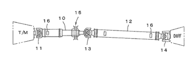
図1によりプロペラシャフトを支持するセンターベアリングの概略を説明する。
トランスミッションTMにTM側ユニバーサルジョイント11を介して第1プロペラシャフト10が連結され、第1プロペラシャフト10と第2プロペラシャフト12とが中間ユニバーサルジョイント13を介して連結され、第2プロペラシャフト12とディファレンシャルDIFFとがデフ側ユニバーサルジョイント14を介して連結され、第1プロペラシャフト10がセンターベアリング15にてシャーシ(図示せず)に支持される。なお、16は偏重心を調整するためのバランスウエイトである。
トランスミッションTMからディファレンシャルDIFF間の動力伝達は、第1プロペラシャフト10から第2プロペラシャフト12を介して行われ、ディファレンシャルDIFFの上下動による第1プロペラシャフト10と第2プロペラシャフト12の軸角変動を、各ユニバーサルジョイント10、13、14で吸収する。
ディファレンシャルDIFFは走行中の路面からの反力を受けて上下動と前後の変位を繰り返しており、第1プロペラシャフト10と第2プロペラシャフト12とは常時軸方向と径方向に変位する。
この際センターベアリング15は、第1プロペラシャフト10をシャーシに締結しながら、第1プロペラシャフト10の動きに追従すると共に、各種振動を吸収する防振特性を発揮する機能を有する。
従来のセンターベアリングは、特許文献1、2に示されるように、プロペラシャフトを回転自在に支持する軸受を保持する軸孔部を有し、径方向と軸方向の変位に追従して変形するゴム状弾性体と、ゴム状弾性体をシャーシに保持するブラケットとで構成されている。
このゴム状弾性体は、リジッド(中実)で外殻形状がU字状に形成され、軸孔部の外周に位置して弾性体を貫通するスリットが形成されて構成され、スリットの形状や配置を工夫することで、プロペラシャフトの径方向と軸方向の動きに追従しながらプロペラシャフトを支持し、その上下左右と前後の動きに伴う振動を吸収するようにしている。
ところで、ゴム状弾性体は、その外周面がブラケットと接触して支持されており、ゴム状弾性体に軸方向に過大変位が加わったときやプロペラシャフトが偏芯回転しているときに、接触相手材であるブラケット面と摩擦を繰り返すため、粘着摩擦が発生し、ゴム状弾性体が摩耗して破損することが問題となっている。
また、ゴム状弾性体は、その外周面がブラケットに支持されるため、軸方向の変位および偏心回転変位に対する変形や追従性が十分ではない問題がある。
そこで、本発明の目的は、上記課題を解決し、プロペラシャフトに過大な変位が加わってもブラケットからのゴム状弾性体の脱落を防止でき、しかも確実に防振できるとともに耐久性を向上できるセンターベアリングを提供することにある。
上記目的を達成するために、プロペラシャフトを軸支する軸孔部を有するゴム状弾性体と、ゴム状弾性体をシャーシに保持するブラケットを備えたセンターベアリングにおいて、ゴム状弾性体を、矩形に形成すると共にその矩形のゴム状弾性体の辺部の中央に凹溝を形成し、ブラケットを、矩形のゴム状弾性体を覆うように矩形に形成したことを特徴とするセンターベアリングである。
前記ゴム状弾性体の四隅に、脚側スリットが形成されるのが好ましい。
前記凹溝が、前記ゴム状弾性体の上下辺に形成され、前記ゴム状弾性体の左右辺に沿って金属プレートが埋め込まれ、前記金属プレートと前記軸孔部との間の前記ゴム状弾性体に、プロペラシャフトの左右方向の変位を吸収する大スリットが形成されるのが好ましい。
前記ゴム状弾性体の左右辺の中央部の表裏に窪み部を形成して、その中央部の厚さを薄く形成するのが好ましい。
前記凹溝が、前記ゴム状弾性体の上下左右辺に形成され、前記ゴム状弾性体の四隅にL状の金属プレートが埋め込まれるのが好ましい。
前記ブラケットは、コ字状に形成された一対の分割ブラケットからなり、前記ゴム状弾性体の四隅の脚部が前記ブラケットの四隅に設けた補強リブ間で支持され、前記ゴム状弾性体の上下辺が前記凹溝を介して前記ブラケットの横部材と離間するようにされるのが好ましい。
前記ブラケットの上下辺は、その両端部が前記ゴム状弾性体の厚さと同じに形成され、上下辺の中央部が前記ゴム状弾性体の厚さより幅が大きく形成されるのが好ましい。
前記一対の分割ブラケットは、両分割ブラケットを連結すると共にシャーシにボルト・ナットで締結するためのフランジを備え、そのフランジが幅広なコ字状に形成され、一対の分割ブラケットの四隅に設けた補強ブラケットは、分割ブラケットの分割縦部材の中央部両側から前記ゴム状弾性体の上下辺を支持する横部材にかけてL字状に形成され、その横部材の中央部の幅方向両側に外側に折り返された補強リブが形成されるのが好ましい。
前記横部材の中央部と前記横部材の両端部との接合部には、凹状のボス部が形成されるのが好ましい。
以下、本発明の好適な一実施の形態を添付図面に基づいて詳述する。
図2~図5において、センターベアリング15は、プロペラシャフトを回転自在に支持するゴム状弾性体20と、そのゴム状弾性体20を支持し、シャーシに締結するブラケット21とから構成される。
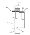
ゴム状弾性体20は、矩形に形成されたブロック体22の中央に軸孔部23が形成され、ブロック体22の上下辺の中央に凹溝24が形成されると共に、その両側にブラケット21と接する脚部25が形成されて構成される。
ブロック体22の左右辺には、その左右辺に沿って板状の金属プレート26が埋設される。
ゴム状弾性体20には、プロペラシャフトから伝達される振動を吸収すべく、弾性力を調整するために種々の形状のスリットが形成される。
すなわち、脚部25に位置したブロック体22の四隅に長穴形状の脚側スリット27が形成され、軸孔部23の左右側の外周と金属プレート26間に位置したブロック体22には、左右大スリット28が形成され、軸孔部23の上下側の外周と上下辺の中央に凹溝24間に位置したブロック体22には、一対の円弧状の上下小スリット29がそれぞれ形成される。
軸孔部23は、図4に示すようにブロック体22の表裏を突出するように形成された軸筒部30からなり、その軸筒部30内に補強用の金属筒31が設けられて形成される。
プロペラシャフトは、図では示していないが軸孔部23内に設けた軸受でゴム状弾性体20に回転自在に支持される。
ゴム状弾性体20の左右辺の上下には、ブラケット21に設けた穴41に係合する突起32が形成される。
ブラケット21は、コ字状に形成された上下一対の分割ブラケット40からなり、その上下の分割ブラケット40に、分割ブラケット40同士を連結すると共にシャーシ(図示せず)にボルト・ナットで固定するための幅広なコ字状のフランジ42が形成される。
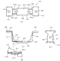
図5(a)~図5(c)に示すように分割ブラケット40は、ゴム状弾性体20の上下辺を支持する横部材43と、横部材43の両端から起立した分割縦部材44と、分割縦部材44に連結されたフランジ42とで構成される。
横部材43は、その中央部43cがゴム状弾性体20の厚さより幅が大きく形成されると共に両端部43eはゴム状弾性体20の厚さと同じに形成される。分割縦部材44は、ゴム状弾性体20の厚さと同じに形成される。
横部材43は、その中央部43cの幅方向両側に外側に折り返された補強リブ45が形成される。また分割縦部材44の中央部両側から横部材43にかけてL字状の補強リブ46が設けられる。
ゴム状弾性体20は、その脚部25がL字状の補強リブ46間に挟まれて支持され、凹溝24が、横部材43の中央部43cの長さと略同じに形成される。
図5(a)に示すように、横部材43の中央部43cと両端部43eの接合部43jは、補強リブ45とL字状の補強リブ46との間に位置し、その接合部43jの強度を上げるべく凹状のボス部47が形成される。
フランジ42は両側が折り返されたコ字状に形成され、そのフランジ42に、分割ブラケット40、40をボルト・ナット等で締結するための長穴48が形成される。
センターベアリング15の組立は、ゴム状弾性体20の軸孔部23をプロペラシャフトに嵌合した状態で、ゴム状弾性体20の上下を分割ブラケット40で挟み込む。この際、ゴム状弾性体20の突起32が、分割ブラケット40の分割縦部材44に形成した穴41に嵌ると共に、脚部25がL字状の補強リブ46間に係合して支持される。
その後、分割ブラケット40のフランジ42の長穴48にてシャーシにボルト・ナットを用いて締結してセンターベアリング15を、図8に示したように組み立てる。
図6、図7は、ゴム状弾性体20の他の実施の形態を示したものである。
図6(a)、図6(b)のゴム状弾性体20は、脚部25に位置したブロック体22の四隅に長穴形状の脚側スリット27を形成する際に、脚部25の弾性力を調整するために脚部溝49をブロック体22の四隅に形成し、その脚部溝49に脚側スリット27を形成したものである。
また、図3の実施の形態では、ゴム状弾性体20の左右辺の上下端部は、分割ブラケット40の四隅のL字状の補強リブ46間で支持され、左右辺は、金属プレート26が埋め込まれて、上下方向の撓みを拘束した形態を示したが、本実施の形態では、上下のL字状の補強リブ46(図5参照)間の左右辺の表裏に窪み部24rを形成して左右辺の中央部22hの厚さを薄く形成することで、また金属プレート26hも中央部22hの幅に合わせて小さく形成することで、上下および軸方向の追従性を向上させることができる。
さらに、ゴム状弾性体20を分割ブラケット40に嵌め込む際に、突起32の先端面をそれぞれ上下辺の方向にテーパ面32tを形成することで、挿入時に分割縦部材44の穴41への係合が容易となる。
図7は、ブロック体22の左右辺にも凹溝24sを形成し、4隅の脚部25にL字状の金属プレート26sを埋め込んでゴム状弾性体20を形成したものである。この実施の形態では、軸孔部23の外周の左右に設けるスリットは、上下の円弧状の小スリット29と同じ小スリット29sで形成したものである。
この図7の実施の形態では、図6の実施の形態より、ゴム状弾性体20の上下方向の撓みが大きく軸方向の大きな変位に追従できると共に上下左右の変位に対する追従性も安定する。
図9は、ブラケット21の変形例を示したものである。
図3、図5、図8に示したようにブラケット21は、上下一対の分割ブラケット40で形成する例を示したが、図9の実施の形態では、横部材53とその横部材53を接続する縦部材54で枠状に形成し、その縦部材54の開放端側にフランジ52を形成し、フランジ52、52間に着脱自在な横部材53sを設けてブラケット21としたものである。このブラケット21の隅部には補強用のL字状のリブ56が設けられ、横部材53にリブ55が形成される。
ゴム状弾性体20は、横部材53sを外した状態でブラケット21内に装入した後、横部材53sを嵌め込み、その横部材53sをフランジ52、52と共にシャーシにボルト・ナットで締結する。
次に、本実施の形態の作用を説明する。
図1で説明したように、センターベアリング15には、プロペラシャフト10の軸方向と径方向の変位が加わるが、ゴム状弾性体20は、実質的にその四隅の脚部25がブラケット21に保持され、径方向の変位と軸方向の変位は、軸孔部23と脚部25間のゴム弾性により吸収される。この際、脚部25の長さを十分に取ることが可能となる。
通常プロペラシャフトの径は、50~130mmφであり、軸孔部は、そのプロペラシャフトの径に対応して形成され、従来の外殻がU字状に形成されるゴム状弾性体の外径は、軸孔部に対して、径が大きくなるように形成されるが、軸方向の変位を十分に吸収することができない問題がある。
本発明のゴム状弾性体20は、辺の長さが120~200mmの矩形に形成しても、軸孔部23から四隅の脚部25の長さは、従来より約1.4(√2)倍長くすることができるため、従来のゴム状弾性体と実質的なサイズは同じでも、十分な弾性変形長さを確保することが可能となる。
左右に大きなスリットもしくは凹部を形成することで、上下と同等の追従性をもたせることができるため、径方向および回転に対する耐久性も向上できる。
また軸方向の変位は、ゴム状弾性体20の上下辺に凹溝24が形成されて、横部材43と直接接触していないため、図10で示したようにゴム状弾性体20が軸方向に撓んでも、ゴム状弾性体20の上下辺と横部材43の接触による粘着摩擦を発生することがない。
さらに、ゴム状弾性体20の左右辺には、金属プレート26が埋め込まれており、ゴム状弾性体20が軸方向に変形する際に、左右辺の変形を抑えてブラケット21に支持することが可能となる。
このように本発明は、ゴム状弾性体20を矩形に形成し、その矩形のゴム状弾性体を覆うブラケット21を矩形に形成し、ゴム状弾性体20の四隅の脚部25をブラケット21で支持し、少なくともゴム状弾性体20の上下辺に凹溝24を設けることで、ゴム状弾性体20の上下辺は、ブラケット21の横部材43と離間しているため、プロペラシャフトに過大な軸方向の変位が加わっても粘弾性摩擦を発生させることなくプロペラシャフトを支持しつつその耐久性を維持することができる。
Claims (9)
- プロペラシャフトを軸支する軸孔部を有するゴム状弾性体と、ゴム状弾性体をシャーシに保持するブラケットを備えたセンターベアリングにおいて、ゴム状弾性体を、矩形に形成すると共にその矩形のゴム状弾性体の辺部の中央に凹溝を形成し、ブラケットを、矩形のゴム状弾性体を覆うように矩形に形成したことを特徴とするセンターベアリング。
- 前記ゴム状弾性体の四隅に、脚側スリットが形成される請求項1記載のセンターベアリング。
- 前記凹溝が、前記ゴム状弾性体の上下辺に形成され、前記ゴム状弾性体の左右辺に沿って金属プレートが埋め込まれ、前記金属プレートと前記軸孔部との間の前記ゴム状弾性体に、プロペラシャフトの左右方向の変位を吸収する大スリットが形成される請求項1又は2記載のセンターベアリング。
- 前記ゴム状弾性体の左右辺の中央部の表裏に窪み部を形成して、その中央部の厚さを薄く形成した請求項3記載のセンターベアリング。
- 前記凹溝が、前記ゴム状弾性体の上下左右辺に形成され、前記ゴム状弾性体の四隅にL状の金属プレートが埋め込まれる請求項1又は2記載のセンターベアリング。
- 前記ブラケットは、コ字状に形成された一対の分割ブラケットからなり、前記ゴム状弾性体の四隅の脚部が前記ブラケットの四隅に設けた補強リブ間で支持され、前記ゴム状弾性体の上下辺が前記凹溝を介して前記ブラケットの横部材と離間するようにされる請求項1~4いずれかに記載のセンターベアリング。
- 前記ブラケットの上下辺は、その両端部が前記ゴム状弾性体の厚さと同じに形成され、上下辺の中央部が前記ゴム状弾性体の厚さより幅が大きく形成される請求項1~5いずれかに記載のセンターベアリング。
- 前記一対の分割ブラケットは、両分割ブラケットを連結すると共にシャーシにボルト・ナットで締結するためのフランジを備え、そのフランジが幅広なコ字状に形成され、一対の分割ブラケットの四隅に設けた補強ブラケットは、分割ブラケットの分割縦部材の中央部両側から前記ゴム状弾性体の上下辺を支持する横部材にかけてL字状に形成され、その横部材の中央部の幅方向両側に外側に折り返された補強リブが形成される請求項6記載のセンターベアリング。
- 前記横部材の中央部と前記横部材の両端部との接合部には、凹状のボス部が形成される請求項6記載のセンターベアリング。
Priority Applications (2)
| Application Number | Priority Date | Filing Date | Title |
|---|---|---|---|
| EP16890591.7A EP3418596B1 (en) | 2016-02-17 | 2016-03-18 | Center bearing |
| AU2016393011A AU2016393011B2 (en) | 2016-02-17 | 2016-03-18 | Center bearing |
Applications Claiming Priority (2)
| Application Number | Priority Date | Filing Date | Title |
|---|---|---|---|
| JP2016-028178 | 2016-02-17 | ||
| JP2016028178A JP6469031B2 (ja) | 2016-02-17 | 2016-02-17 | センターベアリング |
Publications (1)
| Publication Number | Publication Date |
|---|---|
| WO2017141451A1 true WO2017141451A1 (ja) | 2017-08-24 |
Family
ID=59625773
Family Applications (1)
| Application Number | Title | Priority Date | Filing Date |
|---|---|---|---|
| PCT/JP2016/058858 Ceased WO2017141451A1 (ja) | 2016-02-17 | 2016-03-18 | センターベアリング |
Country Status (4)
| Country | Link |
|---|---|
| EP (1) | EP3418596B1 (ja) |
| JP (1) | JP6469031B2 (ja) |
| AU (1) | AU2016393011B2 (ja) |
| WO (1) | WO2017141451A1 (ja) |
Cited By (1)
| Publication number | Priority date | Publication date | Assignee | Title |
|---|---|---|---|---|
| CN117072569A (zh) * | 2023-10-18 | 2023-11-17 | 万向钱潮股份公司 | 一种传动轴的轴承架结构及其传动轴总成 |
Families Citing this family (4)
| Publication number | Priority date | Publication date | Assignee | Title |
|---|---|---|---|---|
| CN108705932B (zh) * | 2018-05-28 | 2021-01-01 | 北京福田戴姆勒汽车有限公司 | 汽车传动总成和车辆 |
| JP6875337B2 (ja) * | 2018-08-29 | 2021-05-26 | 株式会社Ijtt | センターベアリング |
| JP7372041B2 (ja) | 2019-03-29 | 2023-10-31 | 株式会社Ijtt | センターベアリング |
| DE102020130067A1 (de) * | 2020-11-13 | 2022-05-19 | Vibracoustic Se | Vorrichtung zum Lagern einer Zwischenwelle eines Getriebes |
Citations (5)
| Publication number | Priority date | Publication date | Assignee | Title |
|---|---|---|---|---|
| JPS5329028U (ja) * | 1976-08-20 | 1978-03-13 | ||
| JPS5627124U (ja) * | 1979-08-07 | 1981-03-13 | ||
| JPH02127812U (ja) * | 1989-03-29 | 1990-10-22 | ||
| JP2011079394A (ja) | 2009-10-06 | 2011-04-21 | Ud Trucks Corp | 車両用推進軸の支持構造 |
| JP2014219049A (ja) | 2013-05-08 | 2014-11-20 | Nok株式会社 | センターベアリングサポート |
Family Cites Families (2)
| Publication number | Priority date | Publication date | Assignee | Title |
|---|---|---|---|---|
| DE8817113U1 (de) * | 1988-09-24 | 1992-11-05 | Vorwerk & Sohn Gmbh & Co Kg, 5600 Wuppertal | Lager für die elastische Lagerung einer Welle, insbesondere Mittellager für die Gelenkwelle eines Fahrzeugantriebs |
| US6520678B2 (en) * | 2001-03-27 | 2003-02-18 | Spicer Driveshaft, Inc. | Vehicle center bearing assembly including piezo-based device for vibration damping |
-
2016
- 2016-02-17 JP JP2016028178A patent/JP6469031B2/ja active Active
- 2016-03-18 WO PCT/JP2016/058858 patent/WO2017141451A1/ja not_active Ceased
- 2016-03-18 EP EP16890591.7A patent/EP3418596B1/en active Active
- 2016-03-18 AU AU2016393011A patent/AU2016393011B2/en active Active
Patent Citations (5)
| Publication number | Priority date | Publication date | Assignee | Title |
|---|---|---|---|---|
| JPS5329028U (ja) * | 1976-08-20 | 1978-03-13 | ||
| JPS5627124U (ja) * | 1979-08-07 | 1981-03-13 | ||
| JPH02127812U (ja) * | 1989-03-29 | 1990-10-22 | ||
| JP2011079394A (ja) | 2009-10-06 | 2011-04-21 | Ud Trucks Corp | 車両用推進軸の支持構造 |
| JP2014219049A (ja) | 2013-05-08 | 2014-11-20 | Nok株式会社 | センターベアリングサポート |
Cited By (2)
| Publication number | Priority date | Publication date | Assignee | Title |
|---|---|---|---|---|
| CN117072569A (zh) * | 2023-10-18 | 2023-11-17 | 万向钱潮股份公司 | 一种传动轴的轴承架结构及其传动轴总成 |
| CN117072569B (zh) * | 2023-10-18 | 2023-12-29 | 万向钱潮股份公司 | 一种传动轴的轴承架结构及其传动轴总成 |
Also Published As
| Publication number | Publication date |
|---|---|
| AU2016393011A1 (en) | 2018-03-01 |
| JP2017144882A (ja) | 2017-08-24 |
| AU2016393011B2 (en) | 2020-09-17 |
| EP3418596A4 (en) | 2019-09-04 |
| EP3418596B1 (en) | 2021-01-27 |
| JP6469031B2 (ja) | 2019-02-13 |
| EP3418596A1 (en) | 2018-12-26 |
Similar Documents
| Publication | Publication Date | Title |
|---|---|---|
| JP6469031B2 (ja) | センターベアリング | |
| US9175739B2 (en) | Engine mount and power unit vibration damping support structure | |
| US11560030B2 (en) | Arm support structure | |
| EP3530500B1 (en) | Stabilizer bushing for adhesive use and stabilizer bar equipped with stabilizer bushing | |
| US10183720B2 (en) | Engine support structure for saddled vehicle | |
| JP6754311B2 (ja) | スタビライザブッシュ | |
| JP2020131931A (ja) | 車両駆動ユニット | |
| JP6053861B2 (ja) | ヨーク遊隔補償装置 | |
| WO2017056415A1 (ja) | エンジンマウント構造 | |
| JP5449052B2 (ja) | 防振装置 | |
| JP5654843B2 (ja) | 防振装置 | |
| JP2008173990A (ja) | プロペラシャフトの支持構造 | |
| JP4932651B2 (ja) | 対向ピストン型ディスクブレーキ | |
| JP7372041B2 (ja) | センターベアリング | |
| JP2007253646A (ja) | スタビライザーブッシュ装置 | |
| JP5317779B2 (ja) | ボンネット支持構造 | |
| JP5187014B2 (ja) | 船外機のマウント装置 | |
| JP6875337B2 (ja) | センターベアリング | |
| JP2006290238A (ja) | 車両用懸架装置及び弾性支持装置 | |
| JP5713339B2 (ja) | 車両のエンジンマウント | |
| JP2008132942A (ja) | キャスタ | |
| KR20070045604A (ko) | 프로펠러샤프트 센터베어링부의 변형방지 구조 |
Legal Events
| Date | Code | Title | Description |
|---|---|---|---|
| 121 | Ep: the epo has been informed by wipo that ep was designated in this application |
Ref document number: 16890591 Country of ref document: EP Kind code of ref document: A1 |
|
| ENP | Entry into the national phase |
Ref document number: 2016393011 Country of ref document: AU Date of ref document: 20160318 Kind code of ref document: A |
|
| NENP | Non-entry into the national phase |
Ref country code: DE |